

Page 1

OWNER'S MANUAL
DC-1200FS Dust Collector with Floor Sweep
JET EQUIPMENT & TOOLS, INC. P.O. BOX 1349 Phone:253-351-6000
A WMH Company Auburn, WA 98071-1349 Fax: 1-800-274-6840
www.jettools.com e-mail jet@jettools.com M-708629 09/00
Page 2

Important Information
2-YEAR JET offers a two-year limited
LIMITED WARRANTY warranty on this product
REPLACEMENT PARTS
Replacement parts for this tool are available directly form JET Equipment & Tools.
To place an order, call 1-800-274-6848. Please have the following information ready:
1. Visa, MasterCard, or Discover Card number
2. Expiration date
3. Part number listed within this manual
4. Shipping address other than a Post Office box.
REPLACEMENT PART WARRANTY
JET Equipment & Tools makes every effort to assure that parts meet high quality and durability
standards and warrants to the original retail consumer/purchaser of our parts that each such part(s) to be
free from defects in materials and workmanship for a period of thirty (30) days from the date of purchase.
PROOF OF PURCHASE
Please retain your dated sales receipt as proof of purchase to validate the warranty period.
LIMITED TOOL AND EQUIPMENT WARRANTY
JET makes every effort to assure that its products meet high quality and durability standards and warrants to the
original retail consumer/purchaser of our products that each product be free from defects in materials and
workmanship as follows: 2 YEAR LIMITED WARRANTY ON THIS JET PRODUCT. Warranty does not apply to
defects due directly or indirectly to misuse, abuse, negligence or accidents, repairs or alterations outside our
facilities or to a lack of m aintenance. JET LIMITS ALL IMPLIED WARRANTIES TO THE PERIOD SPECIFIED
ABOVE FROM THE DATE THE PRODUCT WAS PURCHASED AT RETAIL. EXCEPT AS STATED HEREIN, ANY
IMPLIED WARRANTIES OR MECHANTABILITY AND FITNESS ARE EXCLUDED. SOME STATES DO NOT
ALLOW LIMITATIONS ON HOW LONG THE IMPLIED WARRANTY LASTS, SO THE ABOVE LIMITATION MAY
NOT APPLY TO YOU. JET SHALL IN NO EVENT BE LIABLE FOR DEATH, INJURIES TO PERSONS OR
PROPERY OR FOR INCIDENTAL, CONTINGENT, SPECIAL OR CONSEQUENTIAL DAMAGES ARISING FROM
THE USE OF OUR PRODUCTS. SOME STATES DO NOT ALLOW THE EXCLUSION OR LIMITATION OF
INCIDENTAL OR CONSEQUENTIAL DAMAGES, SO THE ABOVE LIMITATION OR EXCLUSION MAY NOT
APPLY TO YOU. To take advantage of this warranty, the product or part must be returned for examination,
postage prepaid, to an authorized service station designated by our Auburn office. Proof of purchase date and an
explanation of the complaint must accompany the merchandise. If our inspection discloses a defect, JET will either
repair or replace the product or refund the purchase price, if we cannot readily and quickly provide a repair or
replacement, if you are willing to accept such refund. JET will return repaired product or replacement at JET’s
expense, but if it is determined there is no defect, or that the defect resulted from causes not within the scope of
JET’s warranty, then the user must bear the cost of storing and returning the product. This warranty gives you
specific legal rights, and you have other rights, which vary, from state to state.
JET Equipment & Tools •••• P.O. Box 1349, Auburn, WA 98071-1349 •••• (253) 351-6000
2
Page 3

WARNING
1. Read and understand the entire contents of this manual before attempting assembly or
operation. Do not use this machine until proper training and knowledge has been obtained.
2. Do not leave Dust Collector when plugged in. Unplug from outlet when not in use and before
servicing.
3. Do not use outdoors or on wet surfaces.
4. Do not allow to be used as a toy. Close attention is necessary when used near children.
5. Use only as described in this manual. Use only manufacturer’s recommended attachments.
6. Do not use with damaged cord or plug. If Dust Collector is not working as it should, has been
dropped, damaged, left outdoor, or dropped in water, return it to a service center.
7. Do not pull or carry by cord, use cord as a handle, close a door on cord, or pull cord around sharp
edges or corners. Do not run Dust Collector over cord. Keep cord away from heated surfaces.
8. Do not unplug by pulling on cord. To unplug, grasp the plug, not the cord.
9. Do not handle plug or Dust Collector with wet hands.
10. Do not put any objects into the openings. Do not use with any opening blocked; keep free of dust,
lint, hair, and anything that may reduce air flow.
11. Keep hair, loose clothing, fingers, and all parts of body away from opening and moving parts.
12. Do not pick up anything that is burning or smoking, such as cigarettes, matches, or hot ashes.
13. Do not use without dust bag and/or filters in place.
14. Turn off all controls before unplugging.
15. Use extra care when cleaning on stairs.
16. Do not use to pick up flammable or combustible liquids such as gasoline or use in areas where they
may be present.
17. Do not operate without hose connected to the inlet. Hazardous moving parts inside. Unplug before
removing inlet or inlet guard.
18. Make sure the extension cord is in good condition. When using an extension cord, be sure to use
one heavy enough to carry the current your product will draw. An undersize cord will cause a drop
in the line voltage resulting in loss of power and overheating. The table below shows the correct
size to use depending on cord length and nameplate ampere rating. If in doubt, use the next
heavier gauge. The smaller gauge number, the heavier the cord.
Cord Length Cord Gauge
25’ 16 AWG
50’ 16 AWG
100’ 14 AWG
150’ 12 AWG
SAVE THESE INSTRUCTIONS
3
Page 4
Grounding Instructions
Caution!
This tool must be grounded while in use to protect the operator from electric shock.
In the event of a malfunction or breakdown, grounding provides a path of least resistance for electric
current to reduce the risk of electric shock. This tool is equipped with an electric cord having an
equipment-grounding conductor and a grounding plug. The plug must be plugged into a matching outlet
that is properly installed and grounded in accordance with all local codes and ordinances.
Do not modify the plug provided. If it will not fit the outlet, have the proper outlet installed by a qualified
electrician.
Improper connection of the equipment-grounding conductor can result in a risk of electric shock. The
conductor, with insulation having an outer surface that is green with or without yellow stripes, is the
equipment-grounding conductor. If repair or replacement of the electric cord or plug is necessary, do not
connect the equipment-grounding conductor to a live terminal.
Check with a qualified electrician or service personnel if the grounding instructions are not completely
understood, or if in doubt as to whether the tool is properly grounded.
Use only three wire extension cords that have three-prong grounding plugs and three-pole receptacles
that accept the tool’s plug.*
Repair or replace a damaged or worn cord immediately.
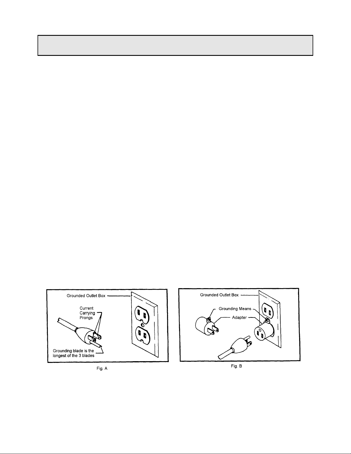
115 Volt Operation
As received from the factory, your Dust Collector is ready to run at 115 volt operation. The Dust
Collector is intended for use on a circuit that has an outlet and a plug that looks the one illustrated in
Figure A. A temporary adapter, which looks like the adapter as illustratedinFigure B, may be used to
connect this plug to a two-pole receptacle, as shown in Figure B if a properly grounded outlet is not
available. The temporary adapter should only be used until a properly grounded outlet can be installed
by a qualified electrician. This adapter is not applicable in Canada. The green colored rigid ear, lug,
or tab, extending from the adapter, must be connected to a permanent ground such as a properly
grounded outlet box, as shown in Figure B.
* Canadian electrical codes require extension cords to be certified SJT type or better.
** Use of an adapter in Canada is not acceptable.
4
Page 5

Specifications: DC-1200FS
Stock Number....................................................................................................................708629
Blower Wheel Diameter........................................................................................................... 12"
Sound Rating at 3 feet.....................................................................................................70-80 db
HoseDiameter...........................................................................................................................4"
Air Flow.......................................................................................................................1,200 CFM
Velocity ..................................................................................................................... 13,730 FPM
Static Pressure....................................................................................................... 14 Inch/Water
Bag Diameter.......................................................................................................................... 14"
Bag Length.............................................................................................................................. 30”
Collector Bag Capacity ..........................................................................................3.5 Cubic Feet
Overall Dimensions....................................................................................... 32"L x 16"W x 72"H
Motor.......................................................................................................................1 1/2HP,1Ph
..............................................................................................................115/230V Prewired 115V
Net Weight (approx.) .......................................................................................................117 Lbs.
Shipping Weight (approx.)...............................................................................................124 Lbs.
Table of Contents Page
Warranty .................................................................................................................................... 2
Warnings ....................................................................................................................... ............. 3
Grounding Instructions................................................................................................................ 4
Specifications............................................................................................................................. 5
Table of Contents....................................................................................................................... 5
Unpacking DC-1200FS............................................................................................................... 6
Contents of Shipping Carton....................................................................................................... 6
Tools Required for Assembly...................................................................................................... 6
Assembly............................................................................................................................... 7-10
Turning the Machine On & Off.................................................................................................. 10
Maintenance........................................................................................................................ 10-11
Parts Breakdown...................................................................................................................... 12
Parts List ............................................................................................................................. 13-14
Wiring Diagrams.................................................................................................................. 14-15
The specifications in this manual are given as general information and are not binding. JET Equipment
& Tools reserves the right to effect, at any time and without prior notice, changes or alterations to parts,
fittings, and accessory equipment deemed necessary for any reason whatsoever.
5
Page 6

WARNING
Read and understand the enti re contents of
this manual before attempting assembly or
operation of the dust collector!
Failure to comply may cause serious injury!
Unpacking
1. Remove all contents from the shipping
carton.
2. Report any damage to your distributor.
3. Do not discard any shipping material until
after the dust collector has been assembled
and is running properly.
Contents of the Shipping Carton
1. Warranty Card
1. Owner's Manual
1. Motor/Fan Assembly
5. Plastic Collector Bags
1. Filter Bag
2. Bag Clamps
2. Supports
1. Handle
4. Casters & Hardware
1. Bag Hanger
1. Lower Stand
1. Upper Stand
1. Base
2. Gaskets (o-ring type)
1. Gasket (foam pad)
1. Inlet
Tools Required for Assembly
6"-8" Adjustable Wrench or 14mm Wrench.
Cross Point or Flat Head Screwdriver.
6
Page 7

Assembly
WARNING
The dust collector must be disconnected
from the power source during assembly
(unplug). Failure to comply may result in
serious injury!
1. Position the base on its side. Mount the two
front, fixed casters on the base with four M6
M6x12 hex cap screws, four lock washers
and four M6 flat washers, Figure 1.
2. Thread two hex nuts onto the caster shaft.
Mount the rear, pivot casters and supporting
bars to the base with two M10 flat washers,
two M10 lock washers and two acorn nuts,
Figure 2. While holding the hex nut that
was threaded onto the caster shaft with a
wrench, tighten the acorn nut.
3. Place the base upright on its casters.
Attach the lower stand, air guard (A, Fig.3)
facing out, to the base with eight M8x20 cap
screws (B, Fig. 3) and eight M8 lock
washers.
7
Page 8

4. Press the smaller gasket (o-ring type), into
the groove of the lower stand, where the
inlet mounts. Attach the inlet (A, Fig. 4) to
the lower stand inlet hole using six M6x12
pan head screws (B, Fig. 4).
5. Press the larger gasket (o-ring type) into the
groove of the upper stand. Attach the upper
stand to the lower stand using eight M6x20
cap screws, eight flat washers, eight lock
washers and eight M6 hex nuts (A, Fig. 5).
6. Attach the handle (A, Fig. 6) to the support
tubing using four M6x50 cap screws, four
M6 flat washers, four M6 lock washers and
four M6 hex nuts (B, Fig. 6).
8
Page 9

7. With the assistance of another person lift
the motor housing onto the upper stand.
8. From the underside attach the motor
housing to the upper stand using eight
M6x16 hex head bolts and eight M6 lock
washers (A, Fig. 7).
9. Attach the supporting bars (A, Fig. 8) to the
motor housing using two M8x16 cap screws,
two M8 flat washers, two M8 lock washers
and two M8 hex nuts (B, Fig.8).
10. Screw a M6 hex nut on the dust bag
hanger. Slip a M6 lock washer and a M6
flat washer onto the rod and screw into the
motor housing (A, Fig. 9).
9
Page 10
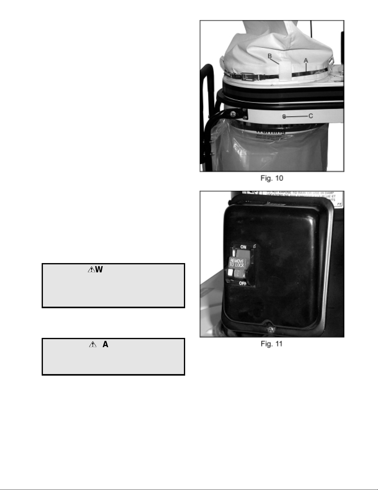
11. Slide the hook on the bag hanger through
the top loop on the filter bag. Thread the
retainer strap (A, Fig. 10) through the loops
on the filter bag (B, Fig.10), and tightly
secure to the upper housing. The retainer
strap should be tight enough to provide a
good seal.
12. Place the plastic collector bag onto the
lower part of the housing. Place the two
holes in the bag over the two bolts (C, Fig.
10) sticking out of the housing. The retainer
strap should be placed, and tightened over
the foam to provide a good seal.
Turning the Machine On & Off
Note: Before hooking up to the power source,
make sure that the switch is in the off position.
1. The dust collector can be turned on by
flipping the switch into the on position.
2. There is a key in the tip of the switch that can
be removed in the off position. When the
key has been removed the dust collector
cannot be turned on, Figure 11.
Maintenance
WARNING
Never perform maintenace on this machine
before turning switch off and removing plug
from power source, unplug.
Failure to comply may cause serious injury!
Removing the Chip Collector Bag
CAUTION
Wearing a particle mask/respirator for
protection against fine dust particles during
cleaning is highly recommended.
1. Disconnect the machine from the power
source, unplug.
2. Shake the filter bag so remaining dust
settles into the chip collector bag.
10
Page 11

3. Loosen the bag clamp, and remove the
collector bag from the dust collector.
Empty the contents into a fire proof metal
container.
4. Attach a new bag using the bag clamp to
secure.
5. Connect the machine to the power source.
Note: Use the proper type hose to connect the
dust collector to the machine being operated.
Dryer vent hose is not acceptable for this
purpose. Contact your nearest JET distributor for
the full line of JET Dust Collector Hoses and
Accessories.
Motor
Make frequent inspections of the motor and
blow out (with low pressure air hose) or vacuum
any accumulation of foreign material in order to
maintain normal motor ventilation.
Electrical Connections
WARNING
All electrical connections must be done by a
qualified electrician. Machine must be
disconnected form the power source, unplug.
Failure to comply may cause serious injury!
If it is necessary to run this unit on 230V,
refer to the wiring diagram found on the inside
cover of the motor junction box.
11
Page 12

Parts Breakdown
12
Page 13

Parts List for the DC-1200FS
Index Part
No. No. Description Size Quantity
1..........427001......................... Upper Housing....................................... .................................. 1
2..........427074......................... Pad........................................................ .................................. 2
3..........427002......................... Impellar Guard....................................... .................................. 1
4..........427058......................... Extension Guard.................................... .................................. 1
5..........427003......................... Gasket................................................... .................................. 1
6..........427004......................... Lower Housing....................................... .................................. 1
7..........427057......................... Locating Pieces..................................... .................................. 2
8..........427005......................... Housing Edge Sleev e ............................ .................................. 1
9..........427415AS.................... Motor.....................................................1 1/2HP, 1Ph.............. 1
............ 4272115-2.................... Motor Fan Cover (not shown)................ .................................. 1
............ 4272115-1.................... Motor Fan (not shown)........................... .................................. 1
............ 991016......................... Running Capacitor (not shown).............. .................................. 1
............ 991400......................... Starting Capacitor (not shown)............... .................................. 1
............ 991401......................... Capacitor Cover (not shown) ................. .................................. 1
10........994532......................... Switch.................................................... .................................. 1
11........999910......................... Power Cord............................................ .................................. 1
12........423023......................... Motor Seal............................................. .................................. 1
13........427009......................... Motor Flange ......................................... .................................. 1
14........430034......................... Flange Gasket ....................................... .................................. 1
15........AB430006.................... Impeller.................................................12” ............................. 1
16........427018......................... Base...................................................... .................................. 1
17........427017......................... Base Guard........................................... .................................. 1
18........427019......................... Fixed Caster.......................................... .................................. 2
19........427020......................... Pivoting Caster...................................... .................................. 2
20........427015......................... Lower Stand.......................................... .................................. 1
21........427033......................... Air Guard............................................... .................................. 1
22........427971......................... Pad........................................................ .................................. 1
23........427028......................... Inlet....................................................... .................................. 1
24........420203......................... Inlet Guard............................................ .................................. 1
25........427027......................... O-ring.................................................... .................................. 1
26........427016......................... Base Gasket.......................................... .................................. 1
27........427013......................... Upper Stand .......................................... .................................. 1
28........427014......................... O-ring.................................................... .................................. 1
29........427012......................... Housing Gasket..................................... .................................. 1
30........427021......................... Support Tubing...................................... .................................. 2
31........427031......................... Handle................................................... .................................. 1
32........427056......................... Plug.......................................................7/8”............................ 2
33........427023......................... Hanger .................................................. .................................. 1
34........709561......................... Filter Bag............................................... .................................. 1
35........427024......................... Retainer Strap....................................... .................................. 2
36........709560......................... Collection Bags...................................... ................................ 10
41........KS070720.................... Key........................................................7x7x20....................... 1
42........TS-1540041................. Nut........................................................M6 ........................... 21
43........NH081300.................... Nut ........................................................M8 ............................. 2
44........TS-0561031................. Nut........................................................3/8”-16UNC ................ 2
45........TS-059303................... Acorn Nut ..............................................3/8”-16UNC................ 2
46........TS-0561072................. Nut........................................................5/8”-18UNF................ 1
47........TS-1482021................. Cap Screw............................................. M6x12........................ 8
48........SH069400.................... Hex Head Bolt.......................................M6x16........................ 8
49........TS-1482041................. Cap Screw............................................. M6x20...................... 10
50........TS-1482101................. Cap Screw............................................. M6x50........................ 4
51........TS-1490021................. Cap Screw............................................. M8x16........................ 6
52........TS-1490031................. Cap Screw............................................. M8x20........................ 8
53........SF069300 .................... Pan Head Flange Bolt............................M6x12...................... 14
54........SR069200.................... Hex Socket Cap Bolt .............................M6x8.......................... 2
13
Page 14

55........ST039304 .................... Tapping Screw.......................................M3.5x12 ................... 11
56........ST040200 .................... Tapping Screw.......................................M4x10...................... 28
57........TS-1550041................. Flat W asher...........................................M6 ........................... 13
58........TS-1550061................. Flat W asher...........................................M8 ............................. 6
59........TS-1550071................. Flat W asher...........................................M10............................ 2
60........WF164030 ...................Flat Washer...........................................M16............................ 1
61........TS-1551041................. Spring Washer.......................................M6 ........................... 33
62........TS-1551061................. Spring Washer.......................................M8 ........................... 14
63........TS-1551071................. Spring Washer.......................................M10............................ 2
Wiring Diagram
14
Page 15

Wiring Diagram
15
 Loading...