

Page 1
Operating Instructions and Parts Manual
Dust Co llector
Models: DC-1100BK,-1100CK,-1100MK
DC-1100BK DC-1100CK
WALTER MEIER (Manuf acturing) Inc.
427 New Sanford Road
LaVergne, Tennessee 37086 Part No. M- 708636
Ph.: 800-274-6848 Revision E 03/2011
www.walt er meier.c om Copyright © 2011 Walt er Meier (M anufacturi ng) Inc.
Page 2
W arranty and Service
Walter Meier (Manufacturing) Inc., warrants every product it sells. If one of our tools needs service or repair, one of our
Authorized Service Centers located throughout the United States can give you quick service. In most cases, any of these
Walter Meier Authorized Service Centers can authorize warranty repair, assist you in obtaining parts, or perform routine
®
maintenance and major repair on your JET
1-800-274-6848.
MORE INFORMATION
Walter Meier is consistently adding new products to the line. For complete, up-to-date product information, check with your
local Walter Meier distributor, or visit waltermeier.com.
WARRANTY
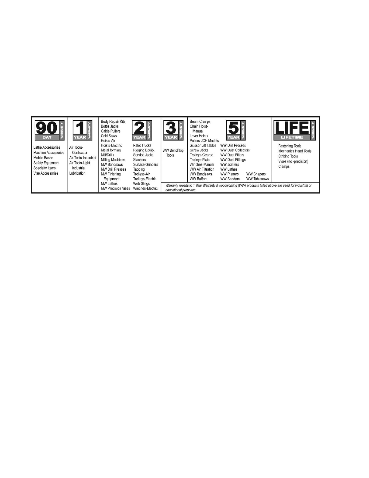
JET products carry a limited warranty which varies in duration based upon the product (MW = Metalworking, WW =
Woodworking).
WHAT IS COVERED?
This warranty covers any defects in workmanship or materials subject to the exceptions stated below. Cutting tools,
abrasives and other consumables are excluded from warranty coverage.
WHO IS COVERED?
This warranty covers only the initial purchaser of the product.
WHAT IS THE PERIOD OF COVERAGE?
The general JET warranty lasts for the time period specified in the product literature of each product.
WHAT IS NOT COVERED?
Five Year Warranties do not cover woodworking (WW) products used for co mmercial, industrial or educational purposes.
Woodworking products with Five Year Warranties that are used for commercial, industrial or education purposes revert to a
One Year Warranty. This warranty does not cover defects due directly or indirectly to misuse, abuse, negligence or
accidents, normal wear-and-tear, improper repair or alterations, or lack of maintenance.
HOW TO GET SERVICE
The product or part must be returned for examination, postage prepaid, to a location designated by us. For the name of the
location nearest you, please call 1-800-274-6848.
You must provide proof of initial purchase date and an explanation of the co mplaint must accompany the merchandise. If
our inspection discloses a defect, we will repair or replace the product, or refund the purchase price, at our option. We will
return the repaired product or replacement at our expense unless it is determined by us that there is no defect, or that the
defect resulted from causes not within the scope of our w arranty in which case we will, at your direction, dispose of or
return the product. In the event you choose to have the product returned, you will be responsible for the shipping and
handling costs of the return.
HOW STATE LAW APPLIES
This warranty gives you specific legal rights; you may also have other rights which vary from state to state.
LIMITATIONS ON THIS WARRANTY
WALTER MEIER (MANUFACTURING) INC., LIMITS ALL IMPLIED WARRANTIES TO T HE PERIOD OF THE LIMITED
WARRANTY FOR EACH PRODUCT. EXCEPT AS STATED HEREIN, ANY IMPLIED WARRANTIES OR
MERCHANTABILITY AND FITNESS ARE EXCLUDED. SOME STATES DO NOT ALLOW LIMITATIONS ON HOW LONG
THE IMPLIED WARRANTY LASTS, SO THE ABOVE LIMITATION MAY NOT APPLY TO YOU.
WALTER MEIER SHALL IN NO EVENT BE LIABLE FOR DEATH, INJURIES TO PERSONS OR PROPERTY, OR FOR
INCIDENTAL, CONTINGENT, SPECIAL, OR CONSEQUENTIAL DAMAGES ARISING FROM THE USE OF OUR
PRODUCTS. SOME STATES DO NOT ALLOW THE EXCLUSION OR LIMITATION OF INCIDENTAL OR
CONSEQUENTIAL DAMAGES, SO THE ABOVE LIMITATION OR EXCLUSION MAY NOT APPLY TO YOU.
Walter Meier sells through distributors only. The specifications in Walter Meier catalogs are given as general information
and are not binding. Members of Walter Meier reserve the right to effect at any time, without prior notice, those alterations
to parts, fittings, and accessory equipment which they may deem necessary for any reason whatsoever. JET
products are not sold in Canada by Walter Meier.
tools. For the name of an Authorized Service Center in your area call
®
branded
2
Page 3

Table of Contents
Warranty and Service .................................................................................................................................2
Table of Contents ......................................................................................................................................3
Warnings ...................................................................................................................................................4
In trodu c tion ...............................................................................................................................................5
Spe ci fic ati ons ............................................................................................................................................6
Unpacking .................................................................................................................................................7
Shipping Content .......................................................................................................................................7
Base Unit ...............................................................................................................................................7
Canister Filter Kit ....................................................................................................................................8
30-Micron Bag Filter Kit...........................................................................................................................8
5-Micron Bag Filter Kit ............................................................................................................................8
Base Unit Assembly ...................................................................................................................................9
Base ......................................................................................................................................................9
Motor and Fan Assembly ........................................................................................................................9
Connector Housing .................................................................................................................................9
Hose.................................................................................................................................................... 10
Filter Bag Kit Assembly ............................................................................................................................ 11
Filter Bag Installation ............................................................................................................................ 11
Collector Bag Installation (30 Micron Kit) ................................................................................................ 11
Collector Bag Installation (5 Micron Kit) .................................................................................................. 11
Canister Kit Assembly .............................................................................................................................. 12
Canister Filter ....................................................................................................................................... 12
Collector Bag ....................................................................................................................................... 12
Electrical Connect io ns .............................................................................................................................. 13
Turning the Machine O n & Off .................................................................................................................. 13
All Models ............................................................................................................................................ 13
Remote Contr ol ( Optional Accessory ) .................................................................................................... 1 3
Dust Co lle c tor RF Remote Po wer Co ntrol (Optional) .................................................................................. 13
Turning the DC-RC On & Off ................................................................................................................. 13
Changing Operating Frequency ............................................................................................................. 14
Installing the DC-RC Remote Power Control (Optional Accessor y)........................................................... 14
Maintenance............................................................................................................................................ 15
Cleaning the Filter Bag – DC-1100BK and DC-1100MK .......................................................................... 15
Removing the Collector Bag–DC-1100BK .............................................................................................. 15
Cleaning the Filter – DC-1100CK ........................................................................................................... 15
Removing the Collector Bag–DC-1100CK and DC-1100M K .................................................................... 15
Motor ................................................................................................................................................... 15
Connecting the Dust Collector to a Machine ........................................................................................... 15
Grounding the Dust Collection System ................................................................................................... 15
Parts Breakdown – DC-1100 D ust Collectors ......................................................................................... 16
Parts List – DC-1100 Dust Collectors ..................................................................................................... 17
Canister Filter Assembly ....................................................................................................................... 18
30-Micron Filter Bag Assembly .............................................................................................................. 19
5-Micron Filter Bag Assembly ................................................................................................................ 20
Wiring Diagram – DC-1100 Dust Collector s ............................................................................................ 21
3
Page 4

Warnings
1. Read and understand t he entire owner's ma nual before at t empting assemb ly or oper ation.
2. Read and understand the war ni ngs posted on the machine and in this manual. Failure t o comp ly w ith all of
these warnings may cause serio us injury.
3. Replace the warning labels if they become obscured or removed.
4. This dust collector is designed and intended for use by properly trai ned and experienced personnel o nly. If
you are not familiar wit h the proper and safe operatio n of a dust c ollector, do not use until proper training
and knowledge have been obtained.
5. Do not use this dust collector for other than its intended use. If used for other purposes, Walter Meier
(Manufacturing) I nc., disclaims a ny real or implied war ranty a nd holds itself harmless from a ny injury t hat
may result from that use.
6. Always wear approved safety glasses/face shields while using this dust collector. Everyday eyeglasses
only have impact r esistant lenses; t hey are not safety glasses.
7. Before operating this dust collector, remove tie, rings, watches and other jewelry, and roll sleeves up past
the elbows. Remove all loose clot hing a nd confine long hair. Non-slip foot wear or anti-skid floor strips are
recommended. Do not wear gloves.
8. Wear ear pr otect or s (plugs or muff s) during extended periods of operation.
9. Some dust created by power sanding, sawing, grinding, drilling and other constr uction activities contain
chemicals known to cause cancer, birth defects or other reproductive harm. Some examples of these
chemicals are:
• Lead from lead based paint.
• Crystalline silica from bricks, cement and ot her masonry products.
• Arsenic and chromium fr om chemically treated lumber.
Your risk of expos ure var ies, depe nding on how often you do t his type of wor k. To reduce your exposure
to these che micals, wor k in a well-ventilated area and work with approved safety equipme nt, such as face
or dust masks that are specifically desig ned t o f ilter out microscopic particles.
10. Do not operate this machine while tired or under the influence of drugs, alcohol or any medicat io n.
11. Make cer t ain the switch is in the OFF position before co nnecti ng the machine to the power supply.
12. Make cer t ain the machine is properly grounded.
13. Make all machine adjustme nts or maintenance with the machine unplugged from the power source.
14. Remove adjusti ng keys and wr enches. Form a habit of checking to see that keys and adjusting wrenches
are removed from the machine before t ur ning it on.
15. Keep safet y guards i n place at all times when the machine is in use. If r emoved for maintena nce purposes,
use extreme caution and replace the guards im mediately.
16. Check damaged parts. Before f urt her use of t he machi ne, a g uard or ot her part t hat is da maged s hould be
carefully checked to determine that it will operate properly and perform its intended function. Check for
alignment of moving parts, binding of moving parts, breakage of parts, mounti ng and any other conditions
that may affect its operation. A guard or other part that is damaged should be properly repaired or
replaced.
17. Provide for adequate space surrounding work area and non-glare, overhead lighti ng.
18. Keep the floor around t he machine clean and free of sc r ap material, oil and grease.
19. Keep visitors a saf e dist ance from the wor k ar ea. Keep children away.
4
Page 5

20. Make your workshop child proof with padlocks, master switches or by removing star t er keys.
21. Give your work undivided attention. Looking around, carrying on a conversation and “horse-play” are
careless acts that can result in serious injury.
22. Do not use the d ust c ollector for anything except w ood dust. Mat erials such as liq uids, m etal shavings,
metal dust, screws , glass, plastic or rock c an cause sparks and/or damage when coming into contact with
any part of the dust collector.
23. Use recommended accessor ies; improper acc essor ies may be ha zardo us.
24. Maintain tools with care. Follow instructions for lubricating and c hangi ng accessories.
25. Turn off the machine before cleaning. Use a brush or compressed air to remove chips or debris — do not
use your h and s.
26. Do not stand on the machine. Serio us injury co uld occur if the machine tips over.
27. Never leave the machine running unattended. Turn the power off and do not leave the machine until it
comes to a complete stop.
28. Remove loose items a nd unnecessary w or k pieces f r om the area befor e starting the machine.
29. Never place ha nds near the inlet of the machine.
30. Always make cert ain mac hine is off and unplugged whe n making any connectio ns to t he inlet.
Familiarize yours elf with the f ollow ing saf et y not ices used in t his manual:
This means that if precautions are not heeded, it may result i n minor injury and/or possible
machine damage.
This means that if precautions are not heeded, it may result i n serio us injury or possibly e ven
death.
- - SAVE THESE I NSTRUCTI ONS - -
Introduction
This manual is provided by Walter M eier (Manufact uring) Inc., coveri ng the safe operat ion and mainte nance
procedures for model DC-1100 Series Dust Collectors . This manual contai ns i nstr uctio ns on inst allatio n, saf et y
precautions, ge neral operating proced ures, maintenance instr uctions and parts br eakdown. This machine has
been designed and constructed to provide years of trouble free operation if used in accordance with
instructions set f orth in this manual. If there are any questions or comments, please contact either your local
supplier or Walter M eier . Walter Meier can also be reached at our website: w ww.w alt er meier.com.
5
Page 6

Specifications
DC-1100BK (Base Mac hine w ith 30 Micron Filter Bag Kit) ..............................................................708636K
DC-1100MK (Base Machi ne with 5 Micron Filter Bag Kit) ............................................................. 708636MK
DC-1100CK (Base Mac hi ne with Canister Filter Kit) .................................................................... 708636CK
Base Machine (All Models)
Model .....................................................................................................................................DC-1100
Stock Number ........................................................................................................................... 708636
Impeller Diameter ............................................................................................................................. 11
Sound Rating at 3 foot distance ................................................................................................ 70-80 db
1-Hose Connection Diameter (in.)........................................................................................................ 6
2-Hose Connection Diameter (in.)........................................................................................................ 4
Air Flow (CFM) .............................................................................................................................1,100
Velocity at 4” (FPM) ......................................................................................................................8,464
Static Pressure (inch of water)........................................................................................................ 10.5
Overall Dimensions, approx. (with filter kit installed) (in.) ............................................... 37L x 28W x 79H
Motor ................................................... TEFC, 1-1/2 HP, 1PH, 115/230V, Prewired 115V, 11/5. 5 A, 60Hz
Net Weight, approximate (lbs) ......................................................................................................... 103
30 Micron Filter Bag Kit
Stock Number ......................................................................................................................... 708636F
Filter Bag Efficiency .......................................................................................96% of 30 micron particles
Filter Bag Length, i nstalled (in.) ......................................................................................................... 32
Filter and Collector Bag Diameter (in.) ............................................................................................... 2 0
Collector Bag Capacity ( cu. f t .) ......................................................................................................... 5.3
Collector Bag Length (in.) ................................................................................................................. 29
5 Micron Filter Bag Kit
Stock Number ...................................................................................................................... 708636MF
Filter Bag Efficiency .....................................98% of 5 micron particles; 92% of 3 micron; 74% of 1 micron
Filter Bag Length, i nstalled (in.) ......................................................................................................... 32
Filter and Collector Bag Diameter (in.) ............................................................................................... 2 0
Collector Bag Capacity ( cu. f t .) ......................................................................................................... 5.3
Collector Bag Length, installed (in.) ................................................................................................... 29
Canister Filter Kit
Stock Number .........................................................................................................................708639B
Canister Length (in.) ......................................................................................................................... 25
Canister Efficiency................................................... 86% of 1 micron particles; 98% of 2 micron particles
Collector Bag Diameter (in.) .............................................................................................................. 20
Collector Bag Capacity ( cu. f t .) ......................................................................................................... 5.3
Collector Bag Length, installed (in.) ................................................................................................... 29
IR Re mo te Control Unit (Optional Accessory)
Stock Number (main unit and remote co ntrol sw it ch) (115V only)............................................... 708636C
Stock Number (Remote Control Switch o nly) ............................................................................. 708636T
The above specifications were current at the time this manual was published, but because of our policy of
continuous im provement, Walter Mei er (M anufacturing) Inc., reserves the right to change specifications at any
time and without prior noti ce, without incur r i ng obli gations .
Read and understand the ent ire cont ent s of t his manual bef ore at t emptin g set - up or
operation! Failur e t o comply may cause seri ous in jury.
6
Page 7
Unpacking
Shippi ng Cont ent
The table below lists the shipping cartons that are
included with the models of the DC-1100 Dust
Collector.
1. Locate your particular model and verify that you
have received all of the correct cartons.
2. C heck co nte nts of each carto n against the ship-
ping content listings on this and the following
page.
3. Report any damage to your distributor.
4. Do not discard any shipping material until after
the dust collector has been assembled and is
running properly.
Base Unit
DC-1100BK
DC-1100CK
DC-1100MK
(SN 708636)
x x
x
x
(SN 708636F)
30M Filter Bag Kit
(SN 708636MF)
5M Filter Bag Kit
x
x
(SN 708639B)
Canister Filter Kit
Table – DC-1100 Dust Collector car tons
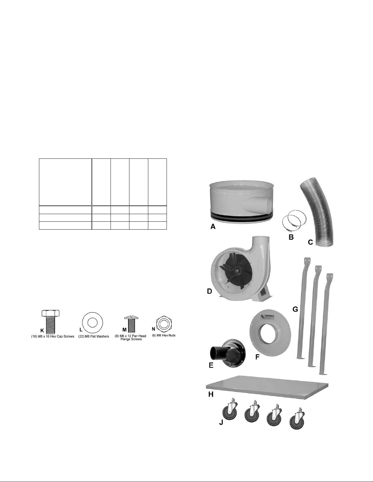
Base Uni t
(SN 708636)
1 – Housing (A)
2 – Hose Clamps (B)
1 – Hose (C)
1 – Impeller (Motor/Fan Assembly) ( D)
1 – Inlet Port (E)
1 – Impeller Cover (F)
3 – Support Legs (G)
1 – Base (H)
4 – Casters (J)
1 – Cone (K)
1 – Support Bracket (L)
1 – Owner's Manual (not shown)
1 – Warranty Card ( not shown)
1 – Hardware Bag, Base Unit (SN DC1100-HP)
Hardware Ba g for Base Unit
(SN DC1100-HP)
16 – M8 x 16 Hex Cap Screws ( K)
22 – M8 Flat Washers (L)
08 – M6 x 12 Pan Head Flange Screw s ( M )
06 – M8 Hex Nuts (N)
Base Un it Hardwa r e
Base Machine Shi pping Contents
7
Page 8
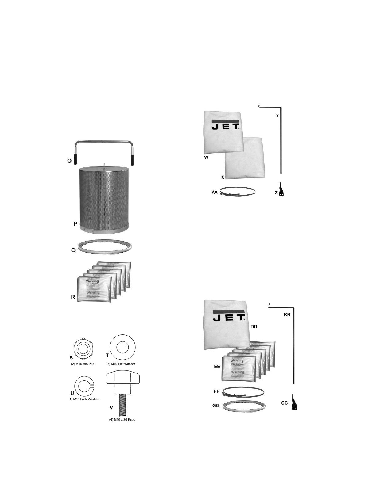
Cani st er Filter Kit
(SN 708639B)
1 – Handle (O)
1 – Canister Filter ( P)
1 – Snap Ring (Q)
5 – Collector Bags (R)
1 – Canister Filter Hardw ar e Bag ( SN DC1100-CHP)
Co nta ins:
(2) M10 Hex Nuts (S)
(2) M10 Flat Washers (T)
(1) M10 Lock Washer (U)
(4) Knobs (V)
30-Micron Bag Filter Kit
(SN 708636F)
1 – Upper Bag Ha nger (Y)
1 – Hanger Bracket (Z)
1 – Collector Bag (X)
1 – Filter Bag (W)
1 – Retainer Strap (AA)
Fil ter Bag Kit Contents
Canister Filter Kit Contents
Canister Filter Hardware
(SN DC1100-CHP)
5-Micron Bag Filter Kit
(SN 708636MF)
1 – Upper Bag Ha nger (BB)
1 – Hanger Bracket (CC)
1 – Filter Bag (DD)
5 – Collector Bags (EE)
1 – Retainer Strap (FF)
1 – Snap Ring (GG)
Canister Filter Hardware
8
Page 9

Base Unit Assembly
Base
1. Install four cast ers to the underside of t he base as
pictured in Fig. 2.
Referring to Figure 1:
2. Thread the hex nut (B) onto the caster shaft. Then
slide the lock washer (A) over the caster shaft.
Thread the caster shaft into the t hreaded hole on
the underside of the base, tur n until snug. Tighten
the nut (B) agai nst the base with a 14mm wrench.
This will give the cas ter p roper clearance.
M otor and Fan Assembly
Referring to Figure 2:
3. Place the base (C) with casters on the ground.
Attach the motor and fan assembly (A) to t he base
using fo ur each M8 x 16 hex cap screw s, and M8
flat w ashers (B). Tighte n with a 13mm wrench.
The dust collector must not be
connected to the power source during assembly.
Failure to comply may resu lt in serious injury!
Figure 1
Figure 2
Referring to Figure 3:
4. Attach impeller cover (A) to impeller housing (D)
using eight M6 x 12 pan head screws (B). Press
the inlet ports (C) onto the i nlet g uard until it snaps
into place.
To reduce the risk of injury from
moving parts, always keep inlet port covered with
the caps provided, if they are not connected to a
hose. Failure to comply may result in serious
injury!
Connector Housing
5. Attach three support legs (A, Fig. 4) to the base
using six M8 x 16 hex cap bolts and six M8 flat
washers (B, Fig. 4). Hand-tighten only at this time.
Figure 3
Figure 4
9
Page 10

6. Install the housing (A, Fig. 5) to two support
legs (B, Fig. 5) using four M8 x 16 hex cap bolts,
eight M8 flat washers, and four M8 hex nuts (C,
Fig. 5). Be sure hose opening faces f an housing.
Note: For filter bag models only – Before attaching
third support brac ket place the hanger bracket (D,
Fig.5) between the support bracket and the
housing. This acti on is not necessary f or canister
filt e r units.
7. Tighten all nuts and bolts at this time wit h a 13mm
wrench.
Figure 5
Hose
Referring to Figure 6:
8. Attach the hose (B) betw een the collector housing
(A) and the im peller housing (D) with two clamps
(C). Tighten the clamps to secure the hose.
This completes the Base Unit assembly. If you
purchased the DC-1100BK or DC-1100MK Dust
Collector (filter bag versions), continue on the
following page. I f you purchased the DC-1100CK Dust
Collector (canister filter version), proceed to Canister
Kit Asse m b ly section on page 12.
Figure 6
10
Page 11

Filter Bag Kit Assembly
If you purchased a D C-1100BK, or DC-1100MK Dust
Collector, this section describes the assembly and
installation of the contents of the Filter Bag Kit (SN
708636F or 708636MF) .
Filter Bag Installation
Referring to Figure 7:
1. Place the hanger (A) on the hanger br acket (B).
2. Slide the filter bag loop (C) over the hanger hook.
3. Feed the retainer strap (D) through the loops on
the filter bag (E) and fasten to the collector
housing (F).
Col l ect or Bag Install at ion (30 Mi cro n Kit)
Referring to Figure 8:
4. I nsert t he ring of the collector bag (A) at an angle
into the housing (B) through the opening at the
bottom. Pull down on the bag to make sure it
“seats” in the ho using.
Figure 7
5. Position t he plastic wi ndow in front so t hat you ca n
easily see when the collector bag is full.
Collector Bag Installation (5 Micron Kit)
The 5-Micron Filter Bag Kit includes clear plastic
collector bags. Refer to Figures 11 and 12 on the next
page, along with the accompanying instructions, to
install these.
After completing the filter bag and collector bag
installation, proceed t o El ectrical Connections.
Figure 8
11
Page 12

Canis ter Kit Assembly
If you purchased Model DC-1100CK Dust Collector,
this section d escribes the assembly and installation of
the contents of the Canister Kit (SN 708639B).
Cani st er Filter
1. Mount the handle onto the canister filter with two
M10 hex nuts, two M10 flat washers, and a M10
lock washer (Figure 9).
2. Mount the canister filter on top of the collector
housing (A, Fig. 5) and tighten the knobs on the
canister f il ter ( Figure 9).
Col l ect or Bag
3. Place the snap ri ng over the top of the plastic bag
and fold the bag over the ring approximately three
inches, as shown in Figure 10.
4. Insert the s nap ring (A, Figure 11) of the collector
bag into t he bottom of the housing at an angle.
5. Pull down on the snap ri ng to make s ure it seat s in
the housing.
Note: Make sure the snap ring “snaps” i nto place
in the housing, and also that the plastic b ag hangs
down approximately 3 inc hes so that there are no
air leaks.
Figure 9
Figure 10
Figure 11
12
Page 13

Electrical Connections
Dust Collector RF Remote
All electrical connections must
be done by a qualified
electrician. All adjustments or repairs must be
done with the dust collector disconnected from
the power source, unplugged. Failure to comply
may result in serious injury!
The DC-1100 dust collectors (all models) are rated at
115/230V, Prewired 115V. Use a plug and outlet
rated at least 20 amps. The circuit for the machine
should also be protected by a minimum 20 amp
circuit breaker or fuse. Keep in mind that a circuit
being used by other machines, t ools, lights, heaters,
etc . at the sa me time will add t o the electr ical load.
A dedicated circ uit to t he dust collector w ill give yo u
the best results since dust collectors are generally
used at the same time other tools are running.
Turning the Machi ne On & Off
This machine is intended f or
indoor use only.
All Models
Before hooking up to the power source, make sure
that the switch is in the off position.
Turn the dust collector on by pressing the Start
button mounted next to the motor. Press the Stop
button to turn off the dust collector.
Remote Co ntrol ( Opti on al Accessory)
The DC-RC RF Remote Power Control unit is
available as an optional accessory (see your dealer
or contact Customer Service by calling the number
on the cover).
Important: The DC-RC Remote Power Control (SN
708636C) ca n be used for activating Dust Collectio n
units powered by 115V only up to 1-1/2HP. If your
dust collector is currently set up for 230V operatio n or
you choose to convert it to 230V at a later time, you
must purchase the DC-RC230 Remote Power
Control unit (SN 708636D).
Power Control (Optional)
The DC-RC Remote Power Control (Figure 14)
should be used for activating Dust Collection units
powered by 115V only up to 1-1/2HP. The DC-RC
Remote Power Control unit is rated at 115V, Single
Phase only. Use an outlet rated at least 20 amps.
The circuit for the device bei ng controlled by the DCRC should also be prot ected by a minimum 20 amp
circuit breaker or fuse.
Before hooking up to the power source, make sure
that the switch is initially i n the off position on both
the dust collector and remote control unit (Figure 12).
Turning the DC-RC On & Off
This machine is intended f or
indoor use only.
1. Plug the dust collector into the main unit
(Figure 14) and plug the main unit into the power
outlet.
To start a machine or device:
2. Turn the machine itself on.
3. On the main unit place the switch to the ON
position (Figure 12 A). The red LED on t he mai n
unit s ho u ld light up.
4. Press the button on the remote control
transmitter (Fig ure 13) t o turn the mac hine on.
5. To stop the machine, press the button on the
re mote co n trol transmitte r again.
Figure 12A Figure 12B
When the machine is running, it can be stopped by
placing the switch on t he main unit in the off positio n
(Figure 12B). To r es t art, repeat st eps 3 and 4.
Figure 13
13
Page 14

Chan ging Operat i ng Frequency
If several devices are controlled by the same type
remote control unit , each remote c ontrol unit can be
set to oper ate at its’ own unique operati ng frequency
as follows:
Referring to Figure 14:
1. Unplug the DC-RC Remo te P ower Co n tr o l unit.
2. Remove the back covers of the main unit (A) and
remote control switch (B).
3. Locate the DIP switch (C) i n each unit.
4. Change the position of the DIP switches in the
main uni t (A) to any combinatio n desired as lo ng
as they are not the same as other units that may
be present and locat ed w it hin the radio fr equency
range.
5. Set the DIP switches (C) in the remote control
switch (B) to match the switch settings in the
main unit (A ).
6. Replace the back covers to the main unit and
remote control switch.
7. Operate a device as described in Turning the
DC-RC On & Off and verify that other devices
using the same type remote co ntrol do not turn
on.
Installing the DC-RC Remote Power
Control (Opt ional Access ory)
The DC-RC Remote Power Control unit can be
placed anywhere for convenience and portability if
used to control other machines or it can be mounted
as a permanent part of a machine, such as t he DC1100 Dust Collector.
To mount t he DC- RC Rem ote Powe r Contr ol (refer to
Figure 15):
Note: Mounting hardware is not included and must
be supplied by the machine’s owner or user.
1. Place RC Power Control Unit (A) on the open
clearing of the base (B) of the dust collector near
the motor (C).
2. Using a marker, mark the base through the
mounting holes of the power control units
mounti ng tabs.
3. Drill two holes (D) through the base where
marked.
4. Insert screws through the tabs a nd base. Place
washers and hex nuts on the threaded ends of
the screw underneath t he base and tighten.
Figure 14
Figure 15
14
Page 15

Maintenance
Never perform maintenance on
this machine before turning switch off and
removing plug from power source. Failure to
comply may cause serious injur y!
Clean i ng th e Fi lter Bag – DC-1100BK and
DC-1100MK
Wearing a particle mask or
respirator for protection against fine dust
particles dur ing cle ani ng is hi ghly recommended.
During first use and aft er cleaning, the filter bag may
allow some dust to escape. This is normal and will
stop after a short per iod of time.
Clean both t he filter and collector bags frequently to
keep the collector' s performance at its optimum. To
clean:
1. Disconnect the machine from the power source.
2. Unhook the filter bag from the hanger and shake
the bag so that the majority of t he dust falls into
the collector bag.
3. Loosen the retaining strap, and remove the filter
bag from the housing.
4. Turn the bag inside out and clean.
5. Turn the bag outside in and re-at t ach to the
housing using the retainer str ap t o secure.
Removi n g the Co llecto r Bag–DC-1100BK
1. Disconnect the machine from the power source.
2. Remove the collector bag by pushing the ring of
the collector bag upwards and pulling the bag
out at an angle.
3. Empty the contents into an appropriate
container.
4. Turn the bag inside out and clean.
5. Turn the bag outside in and insert into the
housing.
To replace the collector bag, refer to Collector Bag
Installation on page 11.
Use the proper type hose to connect the dust
collector to t he machine being operated. Dryer vent
hose is not acceptable f or t his purpose. Co ntact your
nearest JET distributor for the full line of JET Dust
Collector Hoses and Accessories. Customize your
installation and obtain maximum performance with
JET dust hoods, hoses, clamps, fittings, and blast
gates.
Clean i ng th e Fi lter – DC-1100C K
Never perform maintenance on
this machine before turning switch off and
removing plug from power source. Failure to
comply may cause serious injur y!
Clean both the canister filter and collector bags
frequently to keep the collector's performance at its
optimum.
To clean the filter, turn the handle a couple of
rotat ions so the dust falls into the collection bag.
Removi n g the Co llecto r Bag–DC-1100CK
and DC- 1100MK
Wearing a particle mask or
respirator for protection against fine dust
particles dur ing cle ani ng is hi ghly recommended.
1. Disconnect t he machi ne from t he power source
outlet.
2. Remove t he collector bag by pushing t he ring of
the collector bag upwards at an angle and
pulling the bag and snap ring out.
3. Empty the contents into an appropriate
container.
To replace the collector bag, refer to the Collector
Bag Installation on page 12.
Motor
Make fr equent inspections of the motor fan and blow
out (with low pressure air hose) or vacuum any
accumulatio n of for eign mater ial in order t o maintain
normal motor ventilation.
Con necting the Dust Co llecto r t o a
Machine
Use the proper type hose to connect the dust
collector to the machine being operated. Dryer vent
hose is not acceptable for t his purpose. Contact yo ur
nearest JET distributor for the full line of JET Dust
Collector Hoses and Accessories. Customize your
installation and obtain maximum performance with
JET dust hoods, hoses, clamps, fittings, and blast
gates.
Grounding the Dust Collection System
The dust collection system includes the dust collector
and the hose, or ductwork you use to connect the
tools. The dust collector is grounded through the
ground wire in the cord. The hose or ductwork you
use to connect the t ool t o t he dust col lect or m ust also
be grounded.
15
Page 16

Parts Breakdown – DC-1100 Dust Collectors
16
Page 17

Parts L i st – DC- 1100 Dust Collect ors
Order ing Replacement Parts
To order par ts or reach our service depart ment, call 800-274-6848, Monday through Friday ( see our website f or
business hours, w ww.waltermeier.com). Having the Model Number and Serial Number of your machi ne a vailable
when you call will allow us to serve you quickly and accurately.
Index No. Part No. Description Size Qty
1 .............. 411035W ................Impeller Housing............................................................................................. 1
2 .............. 411026W ................Motor Bracket ................................................................................................. 1
3 .............. 998621....................Strain Relief ................................................................................................... 1
4 .............. MA2041J1W ............Motor ...............................................................1-1/2 HP, 1Ph......................... 1
................ DC 1100-50W...........Motor Fan Cover (not shown) .......................................................................... 1
................ DC 1100-51 ..............Motor Fan (not shown) .................................................................................... 1
................ DC 1100-54 ..............Running Capacitor (not shown) ..........................40uf, 250V ............................. 1
................ DC 1100-55 ..............Starting Capac it or ( not shown)...........................400MFD, 125VAC................... 1
................ DC 1100-52 ..............Centrifugal Switch (not shown) ........................................................................ 1
................ DC 1100-53 ..............Centrifugal Switch Rotor (not shown) ............................................................... 1
5 .............. 411051....................Switch Box .................................................................................................... 1
6 .............. 411053....................Switch Plate .................................................................................................. 1
7 .............. 994542....................Switch ........................................................................................................... 1
8 .............. 999910....................Power Cord .................................................................................................... 1
9 .............. 420051....................Motor Packing ................................................................................................ 1
10 ............ AB411040 ...............Impeller ............................................................11” ......................................... 1
11 ............ 411036W ................Inlet Guard ..................................................................................................... 1
12 ............ 427028....................Inlet Port ..........................................................2 @ 4”.................................... 1
13 ............ 420203....................Inlet Cap ........................................................................................................ 1
14 ............ 430034....................Inlet Flange Packing ....................................................................................... 1
15 ............ 411041W ................Base .............................................................................................................. 1
16 ............ 402036....................Pivoting Caster ............................................................................................... 4
17 ............ 420012W ................Hou sing ...........................................................20 ” ......................................... 1
18 ............ 402004W ................Support .......................................................................................................... 3
20 ............ 411009....................Hose .............................................................................................................. 1
21 ............ 420010....................Ring Clamp ......................................................5”........................................... 2
31 ............ ST050204 ...............Tapping Screw .................................................M5x10.................................... 6
32 ............ KS050525 ...............Key ..................................................................5x5x25 mm ............................ 1
34 ............ TS-1540061 ............Hex Nut............................................................M8 ....................................... 10
35 ............ TS-0561031 ............Hex Nut............................................................3/8”-16UNC ............................ 4
36 ............ TS-1490031 ............Hex Cap Screw ................................................M8x20.................................... 1
37 ............ TS-1490011 ............Hex Cap Screw ................................................M8x12.................................... 4
38 ............ TS-1490021 ............Hex Cap Screw ................................................M8x16.................................. 16
39 ............ TS-1490041 ............Hex Cap Screw ................................................M8x25.................................... 4
40 ............ SF069300 ...............Pan Head Scr ew W/Flange ...............................M6x12.................................... 2
41 ............ TS-1550061 ............Flat Washer......................................................M8 ......................................... 1
42 ............ SF069300 ...............Pan Head Scr ew W/Flange ...............................M6x12.................................... 8
43 ............ TS-1550061 ............Flat Wash er......................................................M8 ....................................... 34
44 ............ TS-2361081 ............Lock Washer ....................................................M8 ......................................... 8
45 ............ TS-2361101 ............Lock Was her ....................................................M10 ....................................... 4
46 ............ ST059200 ...............Tapping Screw .................................................M5x8 ..................................... 2
................ DC 1200-53 ..............Grounding Labe l (not s hown) ........................................................................... 1
................ DC 1200-54 ..............Direction Label (not shown) ............................................................................. 1
................ DC 1100-ID ..............I.D. Label (not shown) ..................................................................................... 1
................ DC 1100-HP .............Hardware Package for Base Unit ..................................................................... 1
................ DC 1100-HP2 ...........Hardware Package for Cone Assembly ............................................................ 1
................ DC 1100-WL ............Warning Label (not shown) .............................................................................. 1
17
Page 18

Cani st er Filter Kit (708639 B)
Index No. Part No. Description Size Qty
................ 708639B .................Canister Filter Kit (index #1-24) .........................................................................
1 .............. 331050....................Han dle ........................................................................................................... 1
2 .............. TS-1540071 ............Hex Nut............................................................M10 ....................................... 2
3 .............. TS-1550071 ............Flat Washer......................................................M10 ....................................... 2
4 .............. TS-2361101 ............Lock Wash er ....................................................M10 ....................................... 1
5 .............. BR000052 ...............Rivet ................................................................5-2 ......................................... 3
6 .............. 331014....................Brac ket ................................................................................................... ....... 1
7 .............. 150623....................Pad................................................................................................................ 1
8 .............. 331051....................Soft Grip Handle ............................................................................................. 2
9 .............. TS-1540041 ............Hex Nut............................................................M6 ......................................... 8
10 ............ 708739....................Fil ter .............................................................................................................. 1
11 ............ 331052....................Shaft .............................................................................................................. 1
12 ............ TS-1482041 ............Hex Cap Screw ................................................M6X20 ................................... 4
13 ............ TS-2361061 ............Lock Washer ....................................................M6 ......................................... 4
14 ............ TS-1550041 ............Flat Washer......................................................M6 ......................................... 4
15 ............ 331012....................Scraper .......................................................................................................... 2
16 ............ 331017....................Strip ............................................................................................................... 2
17 ............ 331015....................Press Plate..................................................................................................... 2
18 ............ TS-1482021 ............Hex Cap Screw ................................................M6x12.................................... 4
19 ............ 331037....................Knob .............................................................................................................. 4
20 ............ 331031....................Pad................................................................................................................ 1
21 ............ 331009....................Support .......................................................................................................... 1
22 ............ ST049200 ...............Tapping Screw .................................................M4X8 ..................................... 4
23 ............ 331038....................Snap Ring ...................................................................................................... 1
24 ............ 709563....................Plastic Bag (Package of 5) .............................................................................. 1
................ DC 1100-CHP ..........Canister Hardware Package ..............................................................................
18
Page 19

30-Micron Fi lter Bag Ki t ( 708636F)
Index No. Part No. Description Size Qty
................ 708636F..................30-Micron Filter and Collection Bag Kit (index # 1-5) ...........................................
1 .............. 708698....................Filter Bag ........................................................30 Micron ............................... 1
2 .............. AB410012 ...............Retainer Strap ................................................................................................ 1
3 .............. 708699A .................Collector Bag ................................................................................................. 1
4 .............. 430038....................Hanger .......................................................................................................... 1
5 .............. 523011W ................Hanger Bracket .............................................................................................. 1
19
Page 20

5-Micron Fi lter Bag Ki t ( 708636MF)
Index No. Part No. Description Size Qty
................ 708636MF ...............5-Micron Filter and Collection Bag Kit (index # 1-6) .............................................
1 .............. 708706....................Filter Bag ........................................................5 Micron ................................. 1
2 .............. AB410012 ...............Retainer Strap ................................................................................................ 1
3 .............. 331038....................Snap Ring ...................................................................................................... 1
4 .............. 709563....................Plastic Bag (Package of 5) .............................................................................. 1
5 .............. 430038....................Hanger .......................................................................................................... 1
6 .............. 523011W ................Hanger Bracket .............................................................................................. 1
20
Page 21

Wi ri ng Diagram – DC-1100 Dust Collect ors
21
Page 22

NOTES
22
Page 23

23
Page 24

WALTER MEIER (Manuf acturing) Inc.
427 New Sanford Road
LaVergne, Tennessee 37086
Phone: 800-274-6848
www.waltermeier.com
24
 Loading...