

Page 1
Operating Inst ruct i ons and Parts Manua l
7
This Manual is Bookmarked
Wood Lathe
Model: JWL-1442VS
WMH Tool Gr oup
2420 Vantage Drive
Elgin, Illinois 60123
Phone: 800-274-6848 Revision C 2/05
www.wmhtoolgroup.com Copyright © WMH T oo l Group
08358K Shown
Part Number: M-708358
Page 2

2
This manual has been prepared for the owner and operators of a JET JWL-1442VS Wood Lathe. Its
purpose, aside f rom machine oper ation, is to promot e safety using acc epted operati ng and maint enance
procedures. To obtain maximum life and efficiency from your wood lathe, and to aid in using the machine
safely, read this manual thoroughly and foll ow instr uc tions carefully.
Warranty and Service
WMH Tool Group warrants every product it sells. If one of our tools needs serv ice or repair, one of our
Authorized Repair Stations located throughout the United States can provide quick service or inform ation.
In most cases, a WMH Tool Group Repair Station can assist in aut horizi ng repair work, obtaini ng parts, or
perform routi ne or m ajor maint enance repair on your JET product.
For the name of an Authori zed Repair Station in your area, please call 1-800-274-6848, or visit our web
site at www.wmhtoolgroup.com.
More In formation
Remember, the WMH Tool Group is consistently adding new products to the line. For complete,
up-to-date product inf ormation, check with your local WMH Tool Group distributor, or visit our web site at
www .wmhtoolgroup.com
.
WMH Tool Group Warranty
WMH Tool Group makes every effort to assure that its products meet high quality and durabilit y standards
and warrants to the original retail consumer/purchaser of our products that each product be free from
defects in materials and workmanship as follow: 1 YEAR LIMITED WARRANTY ON ALL PRODUCTS
UNLESS SPECIFIED OTHERWISE. This Warranty does not apply to defects due directly or indirectly to
misuse, abuse, negli gence or accidents, normal wear-and-tear, repair or alterations outside our facilities,
or to a lack of maintenanc e.
WMH TOOL GROUP LIMITS ALL IMPLIED WARRANTIES TO THE PERIOD SPECIFIED ABOVE,
BEGINNING FROM THE DATE THE PRODUCT WAS PURCHASED AT RETAIL. EXCEPT AS STATED
HEREIN, ANY IMPLIED WARRANTIES OR MERCHANTABILITY AND FITNESS ARE EXCLUDED.
SOME STATES DO NOT ALLOW LIMITATIONS ON HOW LONG THE IMPLIED WARRANTY LASTS, SO
THE ABOVE LIMITATION MAY NOT APPLY TO YOU. IN NO EVENT SHALL THE WMH TOOL GROUP
BE LIABLE FOR DEATH, INJURIES TO PERSONS OR PROPERTY, OR FOR INCIDENTAL,
CONTINGENT, SPECIAL, OR CONSEQUENTIAL DAMAGES ARISING FROM THE USE OF OUR
PRODUCTS. SOME STATES DO NOT ALLOW THE EXCLUSION OR LIMITATION OF INCIDENTAL OR
CONSEQUENTIAL DAMAGES, SO THE ABOVE LIMITATION OR EXCLUSION MAY NOT APPLY TO
YOU.
To take advantage of this warranty, the product or part must be returned for ex ami nation, postage prepaid,
to an Authorized Repair Station designated by our office. Proof of purchase date and an explanati on of
the complaint must acc ompany the merchandi se. If our inspect ion discl oses a defec t, we will either r epair
or replace the product at our discretion, or refund the purchase price if we cannot readily and quickly
provide a repair or repl acement. We will return the repaired produc t or repl acement at WMH Tool Group’s
expense, but if it is determined ther e is no defect, or that t he defect resulted from causes not within t he
scope of WMH Tool Group’s warranty, then the user must bear the cost of storing and returning the
product. This warranty gives you specific legal rights; you may also hav e other rights, which vary from
state to state.
WMH Tool Group sells through distri butors only. Members of the WMH Tool Group r eserve the right to
effect at any time, without prior notice, those alterati ons to parts, fittings and accessory equipment, which
they may deem necessary for any r eason whatsoever.
Page 3

3
1. Read and understand the entire owner’s manual bef or e att empting assembly or operation.
2. This wood lathe i s designed and intended for use by properly trained and experienced personnel
only. If you are not familiar with the proper and safe operation of a wood lathe, do not use it until
the proper training and knowledge have been obtained.
3. Always wear approved safety glasses/fac e shields while using this machine.
4. Make certain the machine is properly grounded.
5. Before operating the machine, remove tie, rings, watches, other jewelr y, and roll sleeves up past
the elbows. Remove all loose clothing and confi ne long hair. Do not wear gloves.
6. Keep the floor around the machine clean and free of scrap material, oil and grease.
7. Keep machine guards i n plac e at all times when the machine is in use. If remov ed for
maintenance pur poses, u se extreme caution and repl ace t he guar ds immediately.
8. Do not over reach. Maintain a balanced stance at all times, so that you do not fall or lean against
blades or other moving parts.
9. Make all machine adjustments or maintenance with the machine unplugged from the power
source.
10. Use the r ight tool. Do not forc e a tool or attachment to do a job that it was not designed to do.
11. Replace warning labels if they become obscured or removed.
12. M ak e certain the switch is in the OFF position before connect ing the machine to the power
supply.
13. Give your work undivided attention. Looking ar ound, carrying on a conversati on and "horse-play"
are careless acts that can result in serious injury.
14. K eep v isitors a safe distance fr om the work ar ea.
15. Use recommended accessories; improper accessories may be hazardous.
16. Read and understand warnings posted on the machine and in this manual. F ailur e to comply with
all of these warnings m ay cause seriou s i njury.
17. S ome dust created by power sanding, sawing, grindi ng, drilling and other construction ac tivities
contain chemicals known to cause cancer, birth defects or other reproductive harm. Some
examples of these chemicals are:
• Lead from lead based paint.
• Crystalline silica from bricks, cement and other masonry products.
• Arsenic and chromium from chemically treated lum ber.
Your risk of exposure varies, depending on how often you do this type of work. To reduce your
exposure to these chemicals: work in a well ventil ated area, and work with approved safety
equipment, such as fac e or dust m asks that ar e specif ic ally designed to fil ter out microscopic
particles
18. Do not operate this lathe while under the influence of drugs, alc ohol or any medication.
19. K eep tools sharp and clean for safe and best performance. Dull tools can grab in the work and be
jerked from the operat or ` s hands causi ng serious injury.
20. Chec k the condition of the stock to be turned. Make sure it is free of knots, warpage, checked
ends, improperly made or cured glue joints and other conditions which can cause it to be thrown
out of the lathe.
21. S ec ur ely fasten spur/live centers to the material being used.
22. Chec k c enters and center sockets in the headstock and tailstock to be sure they are free of dir t or
rust and oil lightly before inserting cent er s.
23. Test each set-up by revolving the work by hand to insure it clear s the tool rest and bed. Check the
setup at the lowest speed befor e increasing it to the operating speed.
24. Use the c orrect cutting t ool for the operation to be perform ed and keep all tools sharp.
25. Use l ow speeds for roughi ng and for long or lar ge di ameter work. If v ibration occurs, stop the
machine and corr ect the cause. See the speed recommendation char t on the next page.
Warnings
Page 4

4
Diameter of Work Roug hing R P M General Cutting RPM Finishing RP M
Under 2" 1500 3000 3000
2 to 4" 600 1500 2300
4 to 6" 450 1100 1500
6 to 8" 450 600 1100
8 to 10" 450 600 8 50
10 to 12" 450 600 850
Warnings
SPEED RECOMMENDATIONS
12 to 14" 450 450 6 00
26. When sanding, remove the t ool r est from the machine, apply light pressure and use a slow speed
to avoid heat build up.
27. When turning lar ge diam eter pieces, such as bowls, always operate the lathe at low speeds. See
the speed recommendation chart.
28. Do not attempt to engage the spindle lock pin until the spindle has stopped. If leaving the
machine area, turn it off and wait unti l the spindle stops before departing.
29. M ak e no adjustments except speed changes with t he spindle rotating and always disconnect t he
machine from the power source when performing maintenance to avoid accidental starting or
electric al shock.
30. P r ov ide for adequate space surrounding work area and non-glare, ov er head lighting.
31. When stopping the lat he, never grab the part or faceplate to slow it down. Let t he work coast to a
stop.
32. Use onl y JET factory authorized replacement parts and accessories; other wi se, the warranty and
guarantee are null and void.
33. Do not use this JET wood lathe for other than its intended pur pose. If used for other purposes,
JET disclaims any real or implied warranty and holds itself harml ess from any inj ur y that m ay
result from that use.
Page 5

5
Grounding Instructions
This tool must be grounded while in use to protect the operator from electric
shock.
In the event of a malfunction or breakdown, grounding provides a path of least resistance for electric
current to reduce the risk of electric shock. This tool is equipped with an electric cord having an
equipment-gr ounding conductor and a groundi ng plug. The plug m ust be plugged into a matc hing outlet
that is properly installed and grounded in accor dance with all local codes and ordinances.
Do not modify the plug provided. If it will not fit the out let, have the proper outlet installed by a qual ified
electrician.
Improper connection of the equipment-grounding conductor can result in a risk of electric shock. The
conductor, with insulation having an outer surface that is green with or without yellow stripes, is the
equipment-gr ounding conductor. If repair or replacement of the electric cord or plug is necessary, do not
connect the equi pment-grounding conduct or to a live term inal.
Check with a qualified electrician or service personnel if the grounding instructions are not completely
understood, or if in doubt as to whether the tool is properly gr ounded. Use only three wire extension cords
that have three-prong grounding plugs and three-pole receptacles that acc ept the tool’s plug.
Repair or replace a damaged or worn cord imm ediately.
115 Volt Operation
As received fr om the factory, your sander is ready to run at 115-volt operation. This sander, when wired
for 115 volts, is intended for use on a circuit that has an outlet and a plug that looks the one illustrat ed in
Figure A. A temporary adapter, which looks like the adapter as i llustrated in Figure B, may be used to
connect this plug to a two-pole receptacle, as shown in Figure B if a properly grounded outlet is not
available. T he temporary adapt er should only be used until a properly grounded out let can be instal led by
a qualified elec trician. This adapte r is not applicable in Canada. The green colored rigid ear, lug, or tab,
extending from the adapter, must be connected to a permanent ground such as a properly grounded
outlet box, as shown in Fi gur e B.
The use of an extension cor d is not r ec ommended. However, if you must use one make sure your
extension cord is in good condition. Be sure to use one heavy enough to carry the current your machine
will draw. An undersized cord wil l c ause a drop in the line voltage resulting in power l oss and overheating.
The following table shows the correct size to use depending on the cord length needed and the
nameplate amper e r ating. If in doubt, use the next heavier gauge. Remember, the smaller the gauge
number, the heavier the cord.
Volts Total Length of Cord in Feet
120V 25 50 100 150
AWG
12-16
Amps
14 12 Not Recommended
Page 6

230 Volt Operation
If 230V, single-phase operat ion is desired, the followi ng instructions must be followed:
1. Disconnect th e machine from the power source.
2. This lat he is supplied with four m otor leads that are connect ed for 115V operation, as shown in Figure
A. Reconnect these four motor leads for 230V operation, as shown in F igure B.
3. The 115V attachment plug (A), supplied with the lat he, must be replaced with a UL/CSA listed plug
suitable for 230V oper ation (D). Contact your local Authoriz ed Service Center or qualifi ed electrician
for proper procedur es to install the pl ug. The lathe must com ply wit h all local and national c odes after
the 230-volt plug is installed.
4. The lathe with a 230 volt plug should only be connected to an outlet having the sam e configurati on
(D). No adapter is available or should be used with the 230-volt plug.
Important: In all cases (115 or 230 volts), make certain the receptacl e in question is properl y grounded.
If you are not sure, have a regi ster ed electrician check the receptacl e.
Page 7

7
Introduction
This manual is provided by JET covering the safe operation and maintenance procedures for a Model
JWL-1442VS Wood Lathe. This manual contains instructions on installation, safety precautions, general
operating proc edures, m ai ntenance instr ucti ons and parts breakdo wn. Thi s mac hine has been de signed and
constructed to pr ovide years of troubl e free operation if used in ac cordance to instructi ons set forth in this
manual. If there are any questions or comments, please contact either your local supplier or WMH Tool
Group. WMH Tool Group can also be reached at our web site: www.wmhtoolgroup.com .
Table of Contents
Warranty..................................................................................................................................................2
Warnings.................................................................................................................................................3
Grounding Instructions.............................................................................................................................5
115V Operation........................................................................................................................................5
230V Operation .......................................................................................................................................6
Introduction..............................................................................................................................................7
Table of Contents.....................................................................................................................................7
Specifications..........................................................................................................................................8
Contents of the Shipping Container..........................................................................................................9
Unpacking and Cleanup...........................................................................................................................9
Assembly.................................................................................................................................................9
Stand Legs (optional accessory) ............................................................................................................10
Stand Shelf............................................................................................................................................10
Controls and Feat ur es ...........................................................................................................................10
Lathe Tools............................................................................................................................................12
Mounting Workpiece Between Centers...................................................................................................13
Stock Selection......................................................................................................................................14
Roughing Out ........................................................................................................................................14
Beads, Coves, “V” Cuts and Parting .......................................................................................................15
Sanding and Finishing ...........................................................................................................................16
Face Plate or Bowl Turning....................................................................................................................16
Mounting Stock......................................................................................................................................16
Face Plate or Chuck..............................................................................................................................17
Wood Selection......................................................................................................................................17
Checks and Cracks................................................................................................................................17
Distortion...............................................................................................................................................17
Tools for Bowl T u r ning............................................................................................................................17
To Shape the Outside of a Bowl.............................................................................................................18
To Shape the Interior of a Bowl ..............................................................................................................19
Sanding and Finishing a Bowl................................................................................................................19
Adjusting the Clamping Mechanism.......................................................................................................20
Changing the Belt and B eari ngs.............................................................................................................20
Troubleshooting.....................................................................................................................................21
Part Breakdowns and Parts List .............................................................................................................22
Wiring Diagram......................................................................................................................................31
Page 8
8
Specifications JWL-1442VS
Stock Number................................................................................................................................ 708358
Over Bed ..............................................................................................................................................14"
Swing Over Tool Rest Base..................................................................................................................10"
Distance Between Centers....................................................................................................................42"
Speeds (RPM)..................................................................... 450, 600, 850, 1100, 1500, 1900, 2300, 3000
Spindle Nose...........................................................................................................................1" x 8 T.P.I.
Drive Spindl e Through Hole.................................................................................................................3/8"
Tailstock Spindle Through Hole............................................................................................................3/8”
Tailstock Spindle Travel..........................................................................................................................4”
Tool Rest..............................................................................................................................................12”
Face Plate..............................................................................................................................................6”
Headstock Rotati on ..................................................................................45°, 90°, 135°, 180°, 270°, 360°
Headstock Taper ...............................................................................................................................MT-2
Tailstock Taper..................................................................................................................................MT-2
Spindle Cent er t o Floor ( appr ox .)....................................................................................................43-1/2”
Motor.........................................................................................................................................1 HP, 1Ph
.......................................................................................................................115V/230V, Prewired 115V
Net Weight (approx.).....................................................................................................................200 Lbs.
Shipping Weight (approx.).............................................................................................................215 Lbs.
708358K Shown
The above specifications were current at the time this manual was published, but because of our policy of
continuous im provement, WMH Tool Group reserv es the right to change specif ications at any tim e and
without pri or notic e, without incurring obligations.
Page 9
9
WARNING
Read and understand th e entire contents of
this manual before at t emptin g assemb ly or
operation!
Failure to compl y may cause seri ou s in ju ry!
Contents of the Shipping Containers
1. Lathe
1. Tailstock
1. Headstock
1. Face Plate
1. Tool Rest Body
1. Accessory Package
1. Owner’s Manual and War r anty Card
Accessory Package Box
1. Live Center
1. Spur Center
1. Index Pin
1. Wrench
1. Drift Rod
1. Tool Rest
1. Tool Rest Extension
Unpacking and Clean-Up
1. Remove the shipping container. Do not
discard any shippi ng material until the l athe
is set up and running properly.
2. Remove tailstock, tool rest and headstock
before lifting; see “Adjusting Clamping
Mechanism” on Page 20 on how to remove
the tailstoc k , headstock or tool rest.
3. Rem ove hex cap bolts from skid bottom and
lift the lat he bed, with the help from another
person, off the skid and into position.
4. Mount the lathe t o a solid workbench or refer
to the “Stand Legs (optional assembly)”
instructions, on page 10, if you have
purchased the stand l egs.
5. Clean all rust protected surfaces with a
cleaner degreaser. Clean under the
headstock, t ailstock and tool rest body.
6. Reinstall headstock, tool rest and tailstock
unless you are mounting to optional legs.
Assembly
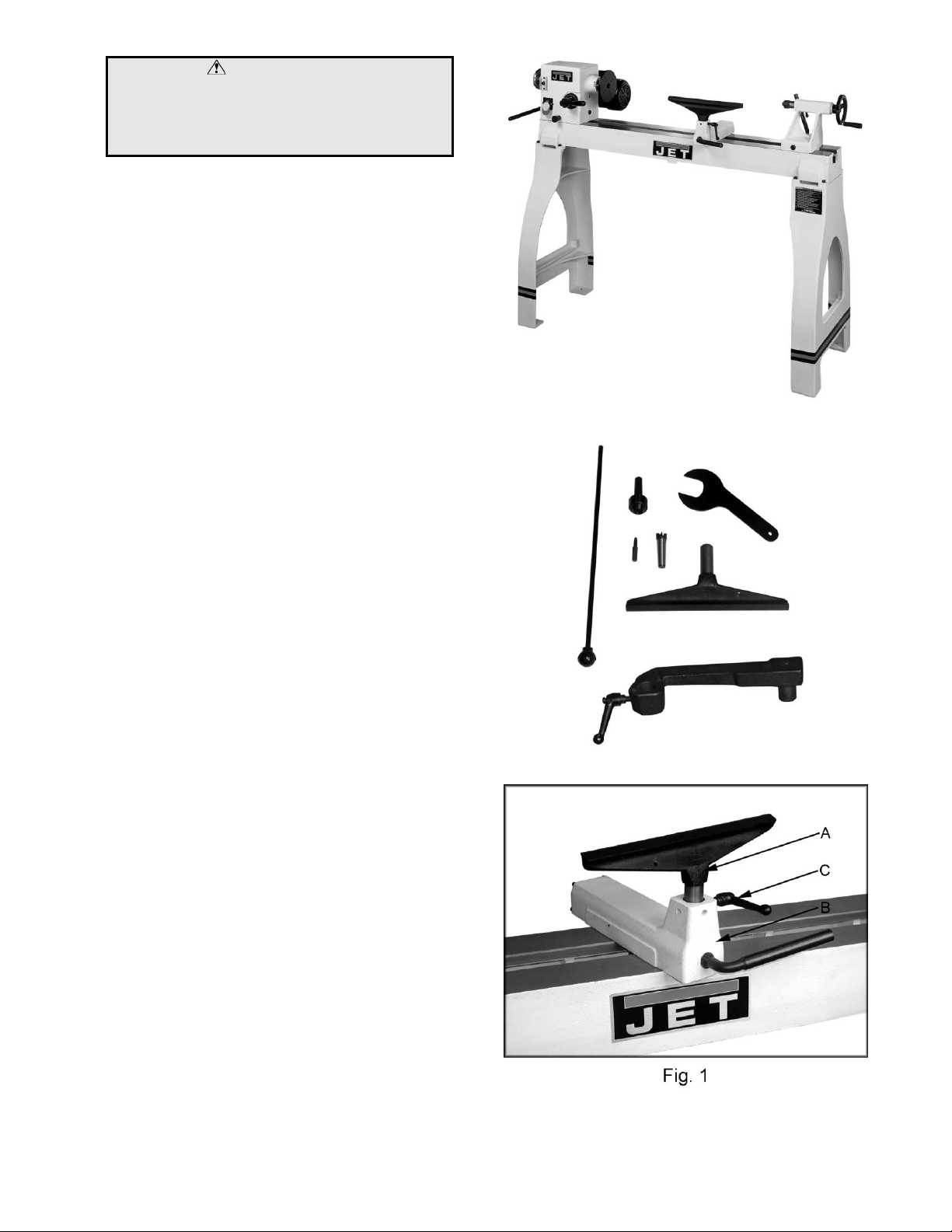
1. Secure tool rest (A, Fig. 1) to tool rest body
(B, Fig. 1) by tightening handle (C, Fig. 1).
Note: For some turning applications, you
may need to assemble the tool rest
extension between the tool rest body and
tool rest.
708358K Shown with optional legs
Contents of Accessory Package
Page 10
1
Stand Legs (optional accessory)
1. At this point the headstock, tailstock and tool
rest should be removed. With help from
another person, lif t the lathe bed and pl ace
onto a workbench.
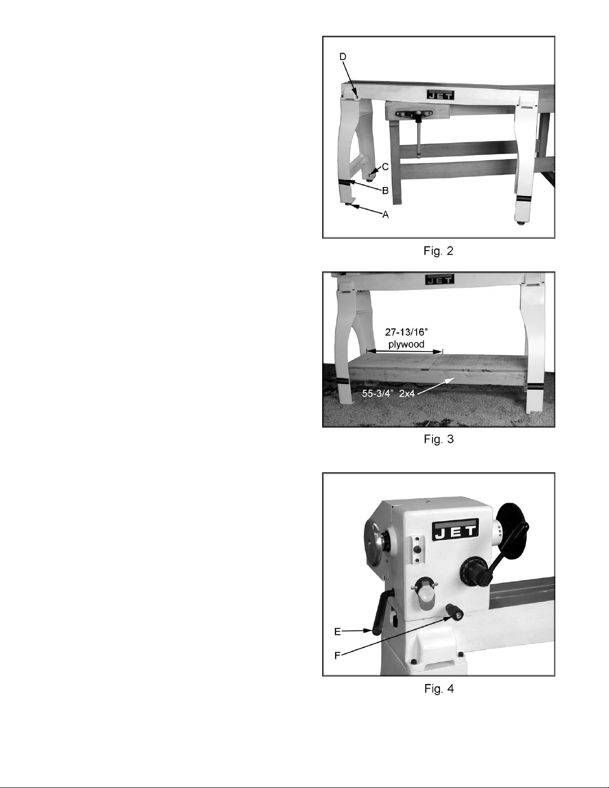
2. Angle lathe bed so that stand leg mount ing
holes are accessible, see Figure 2.
3. Thread adjustable feet (A, Fig. 2) into stand
leg (B, Fig. 2). There is a flat spot on the
shaft near the f oot that will accommodat e a
wrench. Thread a hex nut (C, Fig. 2) onto
shaft and leave loose for now.
4. Mount the leg to lathe bed with four 5/16” flat
washers and four 5/16”-18 x 1-1/2” hex
socket cap screws (D, Fig. 2).
5. Repeat for the other leg.
6. Adj ust the feet so that the lathe rests evenl y
on the floor, and tighten the nuts.
7. Reinstall headstock , tailstock and tool rest.
Stand Shelf
You can make an extra shelf t hat rests between
the legs if you wish, see Figure 3. It will be
useful for storing lathe accessories, or adding
sand bags for som e extra weight. The two 2x4’s
should be 55-3/4” l ong. The plywood should be
ripped into two equal pieces 27-13/16”L x 17”W
so that it can be assembled between the legs.
Use screws to attach the plywood to the 2x4
supports.
Controls & Features
E. Headstock Lock Handle: (E, Fig. 4)
Locks the head in position. Unlock the
handle to position the head in any location
along the lathe bed. Tighten handle when
properly positioned.
F. Headstock Ind exing Pin: (F, Fig. 4)
Turn the knurled knob counter-clockwise to
unlock the plunger. Pull the knob out to
release the headstock. Unlock the
headstock-locking handle and rotate the
headstock. Turn knurled knob cl oc k wise until
it stops to lock plunger.
0
Page 11

1
G. Headstock Spindl e Lo ck: (G, Fig. 5)
Push in pin to keep the spindl e from turning.
CAUTION!
Never press the headstock spindle lock while
the spindle is turning!
H. Headstock On/Off Switch: (H, Fig.5)
Flip the switch up to t urn “ON” the lat he. Fli p
the switch down to turn the lathe “OFF”.
I. Headstock On/Off Switch Key: Remove
key (I, Fig. 5) when in the “OFF” position.
The switch will not work until key is
reinstalled.
J. Headst ock Speed Selector: (J, Fig. 5)
Place handle directly above the desired
RPM speed. Pull handle out and move to
the desired speed, see Figur e 6.
CAUTION!
Only change speeds while the spindle is
turning!
K. Headstock Faceplate: (K, Fig. 7)
Used for turning bowls. There are a number
of screw holes for mounting the workpiece.
Thread the faceplate onto the spindle in a
clockwise direction, and tighten two
setscrews. Remove the faceplate by
loosening two setscrews. Push i n headstock
spindle loc k and use the pr ovided wrench on
faceplate flats.
L. Headstock Spur Cen t er: (L, Fig. 7)
Used for turning between centers. Spindle
taper is MT-2. Remove spur center by
inserting drift rod through the opposite end
of the spindle and knocki ng spur center out.
M. Headstock Indexing Hole: (M, Fig. 7)
Thread indexing pin into the indexing hole
making sure that it locates in the spindle
hole. There ar e 12 holes in the spindl e 30°
apart. Three holes in the headstock c asting
accept the i ndexing pin. These holes are 20°
apart. The combination of holes will allow
you to mark your workpiece for evenly
spaced features.
CAUTION!
Never start the lathe with the index pin
engaged in the spindle!
1
Page 12

1
N. Tool Rest Body Lock Handle: (N, Fig. 8)
Locks the tool rest body in position. Unlock
handle to position the tool rest in any
location along lathe bed. Tighten handle
when properly positioned.
O. Tool Rest Lock Handle: (O, Fig. 8)
Locks the tool rest in position. Unlock the
handle to position tool rest at a specific
angle, or height. Tighten handle when
properly positioned.
P. Tailstock Lock Handl e: (P , Fig. 9)
Locks the tailstock in position. Unlock
handle to position the tool rest in any
location along lathe bed. Tighten handle
when properly positioned.
Q. Tailstock Quill Lock Handle: ( Q , Fig. 9)
Locks the tailstock quill in position. Unlock
handle to position the quill. Tighten handle
when properly positioned.
R. T a ilstock Quill Handwheel: (R, Fig. 9)
Turn the handwheel to position the quill . The
tailstock quill lock handle must be loose to
position quill .
S. Tailstock Live Cent er: (S, Fi g. 9)
Used for turning between centers. Quill
taper is MT-2. Remove live center by
retracting t he quill until live center loosens.
Lathe Tools
If possible, select only high quality, high speed
steel turning tools with long handles. As one
becomes proficient in turning, a variety of
specialty tools for specific applications can be
acquired. The f ollowing tools provide the basic s
for most woodturning projects. See your JET
distribut or for a wide variety of JET woodturning
tools.
Roughing Gouge — used for rapidly cut raw
wood into round stock , see Figure 10.
Deep Fluted Bowl Gouge — used for turning
bowls and plates, see Figure 10.
Spindle Gouge — used for turning beads,
coves and other detai ls, see Figure 10.
Spear — fine scraping and delicat e operations,
such as the forming of beads, parallel grooves
and shallow vees, etc , see Figure 10.
2
Page 13

1
Lathe Tools (continued)
Skew — used to make vees, beads, etc., see
Figure 11.
Square Scraper — used for diameter scraping
and featureless scraping, etc, see Figure 11.
Large Domed Scraper — used to reduce ridges
on the interior of bowls, round edges of bowls,
etc, see Figure 11.
Parting Tool — used to cut directly into the
material, or to make a cut off. Also used for
scraping and to set di am eters, see Figure 11.
For safety and best performance, keep tools
sharp. If a tool stops cutting, or requires
excessiv e pressure to make a cut, it needs to be
sharpened. A num ber of brand name sharpening
jigs and fixtures are available, however, a
woodturner should learn to sharpen tools
freehand.
Mounting Workpiece Between Centers
Spindle turni ng takes place between the cent ers
of the lathe. It requires a spur center in the
headstock and a liv e center in the tailstock.
1. With a ruler locate and mark the center on
each end by going corner to corner, see
Figure 12. Accuracy is not critical on full
rounds but extremely important on stock
where square secti ons are to remain. Put a
dimple in each end of the stock with an awl
or nail.
2. Ext remely hard woods may r equire kerfs cut
into the spur drive end of stock, see Figure
12. You may need to drive the spur center
into the stock with a wood mallet. Note:
Never drive stock onto spur while it is
mounted in the lathe spindle.
3. Install workpiece by inserting the attached
spur center into the spindle taper on the
headstock.
4. Bring tailstock into position, lock it to the
bed, and advance quill with the handwheel
in order to seat the live center into the
workpiece. Lock the quill in place. Make
sure the live center point is centered on your
mark.
5. Move tool rest into position. It should be
parallel to workpiece, approximately at the
centerline, and approximately 1/8" from the
closest part of the workpiece. Lock tool rest
body and tool rest in plac e.
6. Rotate workpiece by hand to check for
proper clearance from tool rest. Note: You
may want to trim off the cor ners of a square
workpiece to make turning a little easier.
7. Start lathe at lowest
the appropriate RPM for the size of stock,
see Figure 6 page 11.
The positi on of the tool rest can be v aried t o suit
the work and operator. After you become
experienced with setting tool rest changing the
position will become second nature for the
workpiece and comfort of the user.
speed and bring it up to
3
Page 14

1
Stock Sele ct ion
Stock for spindles should be straight grained
and free of checks, cracks, knots and other
defects. It should be cut 1/8" to 1/ 4" larger than
the finished di ameter and may require additional
length to rem ove ends if required. Larger stock
should have the cor ners removed to produc e an
octagon making t he piece easier t o rough down
to a cylinder, see Figur e 13.
Roughing Out
1. Use a large roughing gouge and begin
cutting about 2” fr om the tailstock end of the
workpiece. Place the tool on the tool rest
with the heel of the tool on the surface to be
cut.
2. Slowly and gently raise tool handle until
cutting edge comes into contact with the
workpiece. Wor k to t he ri ght t owards the end
of the workpi ece. You never want to start at
the end of a workpiece.
3. Now continue to work the rest of the
workpiece. Roll the flute (hollowed-out
portion) of the tool in the dir ection of the cut,
see Figure 14. Mak e long sweeping cut s i n a
continuous moti on to rough the piece down
to a cylinder . Keep as much of the bevel of
the tool as possible in contact with the
workpiece to ensure control and avoid
catches. Note: Always cut downhill , or from
large diameter to small diameter. Always
work toward the end of a workpiece, never
start cutti ng at t he end.
4. Once the workpiece is roughed down to a
cylinder, smooth it with a large skew. Place
the cutting point near the center of the chisel
and high on the workpiece, see Figure 15.
Touching one of the points of the skew to
the spinning workpiece may cause a catch
and ruin the workpi ec e.
5. Add details to the workpiece with skew,
spindle gouge, etc.
4
Page 15

1
Beads
1. Place the parting tool on the tool rest and
move the tool forward to make t he full bev el
of the tool contact the workpiece. Gently
raise handle to make cut to the appropriat e
depth.
2. Repeat for other side of the bead.
3. Using a small skew or spindle gouge, start in
the center between the two cuts and cut
down each side to form the bead. Roll the
tool in direction of cut.
Coves
1. Use a spindle gouge. With the flute of the
tool at 90 degrees to the workpiece, touch
the center of the cutting edge to the
workpiece and roll in towards the bott om of
the cove. Stop at the bottom; attempting to
go up the opposite side m ay cause the tool
to catch.
2. Move the tool over the desired widt h of the
cove.
3. W ith the flute facing the opposite direction,
repeat step 1 for other side of cov e. Stop at
bottom of cut.
“V” Cuts
1. Use the long point of the skew. Note: Do not
press the long poi nt of the skew directly into
the workpiece to create the "V"; this will
result in a burned or burnished "V" with
fibers being r olled up at both sides.
2. Lightly mark the center of the "V" with the ti p
of the skew.
3. Move the point of the skew to the right half
of the desired widt h of your c ut.
4. With the bevel parallel to the right side of the
cut, raise the handl e and push the tool in to
the desired depth.
5. Repeat from the left side. The two cuts
should meet at the bottom and leave a clean
"V" cut.
6. Additional cuts may be taken to add to either
the depth or width of t he cut.
Parting
1. Place parting tool on tool rest and raise the
handle until it starts to cut and continue to
cut to the desired dept h.
2. If the cut is deep a clearance c ut should be
made alongside the first cut to prevent the
tool tip from burning.
5
Page 16

1
Sanding and Finishing
Leaving clean cuts will reduce the amount of
sanding required. Begin with a fine sandpaper
(120 grit or finer). Coarser sandpaper will leav e
deep scratches that are dif ficult to remove, and
dull crisp detail s. Fold the sandpaper into a pad;
do not wrap sandpaper around your fingers or
the workpiece.
To apply a finish, the workpiece can be left on
the lathe. Turn off lathe and use a brush, or cloth
to apply the finish. Remove excess finish before
restarting l athe. Allow drying and sanding again
with 320 or 400 grit sandpaper. Appl y additional
coats of fini sh and buff.
Face Plate and Bowl Turning
Face plate turning is normally done on the
inboard side of t he headstock over the bed see
Figure 19. You must pivot the headstock 180°
for larger workpieces.
Mounting Stock
Use of a face plat e i s the m ost c ommon m ethod
for holding a block of wood for turning bowls,
and plates.
1. Select stock at least 1/8" to 1/4" larger than
the dimension on the desired finished
workpiece.
2. True one surface of the workpiece for
mounting against the face plate. It is best
to leave extra stock against the faceplate
that can be cut off when the workpiece is
finished.
3. Using the fac eplate as a template, mark t he
location of the mounti ng holes, and drill pil ot
holes of the appr opriate size. If the mounting
screws on the faceplate interfere with the
workpiece, a waste block can be mounted to
the faceplate and then the waste block
mounted to the workpiece by gluing or
screwing, see Fi gur e 20.
4. Both waste block and workpiece should
have good flat surfaces.
5. Push in on the spindle lock and thread face
plate and workpiece onto the spindle.
Tighten setscrews in the faceplate when
secure.
6
Page 17

1
Face Plate or Chuck
While facepl ates are the sim plest, most reliabl e
method of holding a block of wood for turning,
chucks can also be used. A chuck is not a
requirement but is handy when working on more
than one piece at a time. Rather t han removing
screws, you simply open the chuc k and change
workpieces. The most popul ar ones are four jaw
scroll chucks with a variety of jaws to
accommodate different size tenons. Most also
come with a screw chuck as well.
Wood Selection
Firewood is the cheape st, most widely av ailable
stock to use while learning to turn bowls.
Develop skill with each tool before attempti ng to
make a finished pi ece. It is best to start wi th dry
wood, without worrying about drying or
distortion. Once turning becomes comfortable,
try green wood, which cuts very easily. As the
turner gains experience, he or she will find
extraordinary grain and figure in the form of
burls, crot c hes and bark inc lusions.
Checks and Cr acks
Green wood will check and crack. For best
results, leav e logs in as long lengths as you can
handle. As the material starts to dry, surface
cracks will develop on the ends of the log. Cut
off two to three inches and you should f ind good,
sound wood. Also, cut the log in half along the
pith to avoid having it in the finished piec e. Most
checks radiate from the pith. As you turn bowls
from green wood, make sure you maintain a
consistent wall thickness throughout the piece.
Leaving a piece thick in some areas and thin in
others will cause the wood to dry unevenly and
promote checks and crac k s.
Distortion
Distortion is a problem associated with turning
green wood. It will vary from one type of wood to
the next. Typically, fruitwoods tend to distort
more than others do. It also varies with the tim e
of year the tree was cut and how the logs are
stored.
Too ls for Bowl Turning
The deep fluted bowl gouge is the most
essential and versatile tool for most bowl and
faceplate style turning. The bowl gouge is
heavier and easier t o control t han other types of
gouges. It also allows removal of wood much
faster and wit h less vibration t han other gouges.
Most average sized bowl work can be
accomplished with a 3/ 8" or 1/2" bowl gouge. A
1/4" bowl gouge is best suited f or smaller bowls
and light fi nishing cuts. Larger 3/4" and 1" bowl
gouges are only used for extremely large pieces.
Large domed scraper s can also be u sed to help
clean up the interior surfaces of bowls. A light
touch with the scraper sli ghtly tilt ed will elimi nat e
some of the ridges left by a bowl gouge.
7
Page 18

1
To Shape the Outside of a Bowl
1. Odd shaped burls, crotches and other
irregular shaped blanks require special
preparation before mounting in a chuck, or
onto a faceplat e. Remove the bark, if there
is any, from what appears to be the c enter of
the top of workpiece.
2. Drive the spur center into the top of the
workpiece with a wood mallet.
3. Slip the spur center i nto t he headstock t aper
and bring the tailstock, with a live center,
into position. Lock the tailstock to the bed
and advance the spindl e in order to seat the
cup center into workpiece, see Figure 21.
Tighten the quill lock.
4. Position the tool support below the
centerline and about 1/4" from the
workpiece. Note: For larger outboard
turning, an optional outboard turning stand is
used to place the tool support , see your JE T
distributor.
5. Turn the workpiece by hand to ensure
proper clearanc e.
6. Start the lathe at t he lowest speed and bring
it up to the maximum safe speed for the size
of work to be tur ned, see Figure 6 on page
11. If the machine starts to vibrate, lower the
speed until the vibration stops.
7. Rough out the outside of the bowl with the
1/2" deep fluted bowl gouge, holding the tool
firmly agai nst your hip. For best control , use
your whole body to move the gouge through
the workpiece.
8. As the bowl takes shape, work on the
bottom (tailstock end) to accommodate
attaching a face pl ate, see Figure 21.
9. Turn a short tenon (about 1/ 8" l ong) the si ze
of the hole in the faceplate, see Figure 21.
This will all ow centeri ng the workpi ece when
the faceplat e is attached. Note: If you plan
to use a chuck, tur n a tenon of appropr iate
length and diam eter to fi t your c huc k.
10. Stop the lathe, remove the workpiece and
attach the face plate, or chuck.
11. Finish turning the outside of the bowl with
1/2" or 3/8" bowl gouge. Leave additional
material at the base of the bowl for support
while turning the interior. This will be
removed later.
8
Page 19

1
To Shape the Interior of a Bowl
1. Stop the lat he and move the tailstock away.
Remove the center from the tailstock to
prevent bumpi ng it wit h y our elbow.
2. Adjust the tool support in front of the bowl
just below the cent erline, at a right angle to
the lathe bed.
3. Rotate the workpiece by hand t o check the
clearance.
4. Face off the top of the bowl by making a
light shearing c ut across the workpiece, from
rim to center.
5. Place the 1/2" bowl gouge on the tool rest at
the center of the workpiece with the flute
facing the top of the bowl. The tool handle
should be level and pointed toward four
o'clock, see Figure 22.
6. Use your left hand to control the cutting
edge of the gouge, while your right hand
swings the tool handle around towards your
body, see Figure 22. The flute should start
out facing the top of the workpiece, and
rotate upward as it moves deeper into the
bowl to maintain a clean even curve. As the
tool goes deeper into bowl, progressively
work out toward the rim. It may be
necessary to turn the tool rest into the
workpiece, as you get dee per into the bowl.
Note: Try to make one, very light continuous
movement from the rim to the bottom of the
bowl to ensure a clean, sweeping curve
through the workpiece. Should there be a
few small ridges left, a light cut with a large
domed scraper can even out the surface.
7. Develop the wall thickness at the rim and
maintain it as you work deeper into t he bowl.
When the int erior is fi nished, mov e the tool
support to the exterior to re-define the
bottom of the bowl. General rule of thumb:
the base should be approximately 1/3 the
overall diameter of the bowl.
8. Work the tight area around the faceplate or
chuck with 1/4" bowl gouge.
Sanding and Finishing a Bowl
1. Remove the tool rest and begin with a fine
grit sandpaper (120 grit) and progress
through each grit, using only light pressure.
Coarser sandpaper tends to leave deep
scratches that are hard to eliminate. Use
power-sanding techniques to avoid
concentric sanding marks around your
finished piece. Avoid rounding ov er the rim
and foot with sandpaper. Try to keep the
details cri sp. Finish sanding with 220 grit .
2. Remove sanding dust with tack rags, or
compressed air and, with the lathe turned
off, apply the fir st coat of finish. Let it stand
for several minut es and wipe off the excess.
Allow it t o dry before sanding agai n wit h 320
or 400 grit sandpaper.
3. Turn lathe back on and make a separation
cut through the base. S top at about 3" and
use a small fine tooth saw to separate the
bowl from the waste.
4. Apply additional fi nish coats and all ow to dry
before buffing.
9
Page 20

2
Adjusting the Clamping Mechanism
The clamps are pre- set at the fac tory and should
not need any adjustment. However, if
adjustment is needed, remov e the stud (A, Fig.
23). Loosen the locking handle and slide the
headstock, tailstock or tool rest to the edge of
the bed and slightl y turn the hex nut (B, Fig. 23).
Slide back into position and test the handle to
make sure it securely locks.
Changing the Belt and Bearings
Changing belt and bearings can be a difficult
task, and should be performed by a JET
authorized repair station. Remove headstock
and take into a repair station for servicing.
1. Place the belt in its highest speed range. Do
not change speeds while changing t he belt
or bearings.
2. Rem ove the belt c over, and rem ove the belt
from the lower pulley , see Figure 24.
3. Loosen the two setscr ews in the handwheel
enough to unthread the h andwheel (C, Fig.
24).
4. Loosen the socket head cap screw enough
to unthread the clamping nut (D, Fig. 24).
5. Remove one e-ring ( E, Fig. 24) fr om spindle.
6. Loosen the two setscrews in the ri ght hand
pulley (F, Fi g. 24).
7. Use a wood dowel, or aluminum stock to
knock the spindle towards the tailstock. Use
a material that is softer than the spindle so
you do not mushroom the end of the spindle.
Go only far enough to remov e the right hand
pulley and belt from spindle, see Figure 25
when changing the bel t. Note: Mark the key
way on the pulley for easy reference when
reassembling.
8. Now you can replace the belt or bearings.
There are three bear ings #6, 9 and 43 that
can be seen in the “Headstock Assembly,”
page 24.
9. To reassemble rev er se the pr oc edur e. Note:
Key way alignment is critical for installment
and proper operation. Do not force the
pulley. When reinstalling clamping nut
thread it on to the spindle until its snug.
Then back off slight ly and tighten t he socket
head cap screw.
0
Page 21

2
t
Troubleshooting
Problem Possible Cause Solution
Excessive Vibr ation. 1. Workpiec e warped, out of
round, has maj or flaw,
improperly pr epar ed for
turning, or RPM is set too
high
2. Worn spindle beari ngs
3. Worn belt
4. Motor mount bolts loose
5. Lathe on uneven surface
Motor or Spindle St alls or Will not
Start
Motor fails to develop full power. 1. Power line overloaded
Tools tend to grab or dig in. 1. Dull tools
Tailstock Moves When Applying
Pressure
1. Excessive cut
2. Worn motor
3. Broken belt
4. Worn spindle beari ngs
5. Improper cooling on motor
6. Starting or r unning c apac itor
is bad
7. Centrifugal swit c h bad
2. Undersize wires in supply
system, or extension c or d is
too long
3. Low voltage
4. Running capacitor is bad
5. Worn motor
2. Tool support set t oo low
3. Tool support set t oo far from
workpiece
4. Improper tool being used
1. Excessive pressure being
applied by tail stoc k. Note:
The screw action of the
tailstock is capable of
applying excessive pressure
o workpiece and headstock.
Apply only suffi ci ent force by
tailstock t o hol d workpiece
securely in place.
Exc essive pressure can
cause damage to machine.
2. Lathe bed and tailstock
mating surfac es are greasy
or oily.
1. Correct problem by planing,
bandsawing, reduc e the
RPM, or scrap workpiece al l
together
2. Replace bearings
3. Replace belt
4. Tighten bolts
5. Shim lathe bed, or adjust feet
on stand
1. Reduce cut depth
2. Replace motor
3. Replace belt
4. Replace bearings
5. Clean sawdust from motor
fan
6. Replace the starting
capacitor
7. Replace centrifugal switch
1. Correct overload c ondition
2. Increase supply wir e si z e
3. Request voltage check from
power company and c orrect
low voltage condition
4. Replace running capacitor
5. Replace motor
1. Sharpen tools
2. Reposition tool support
height
3. Reposition tool support
closer to workpiec e
4. Use correct tool for operation
1. Slide tailstock down to t he
right side of t he lathe against
the stop. Move headstock
into positi on and apply
pressure to workpiece wit h
tailstock.
2. Remove and clean surfac es
with a cleaner degreaser
1
Page 22

2
Bed Assembly
2
Page 23

2
Bed Assembly
Index Part
No. No. Description Size Qty.
1..........JWL1442-201............... Bed........................................................ ...............................................1
2..........JWL1442-202............... Stud....................................................... ...............................................3
3..........JWL1442-124............... C-Ring...................................................S19.........................................3
4..........TS-0206031................. Hex Socket Cap Screw..........................10-24 x 5/8”.............................4
5..........JWL1442-205............... Tool Rest............................................... ...............................................1
6..........JWL1442-206............... Tool Support Handle.............................. ...............................................1
7..........JWL1442-207............... Tool Support Base................................. ...............................................1
8..........JWL1442-208............... End Cover ............................................. ...............................................1
9..........JWL1442-128............... Bolt........................................................ ...............................................2
10........JWL1442-210A ............ Tool Support Rod................................... ...............................................1
11........JWL1442-211............... Handle................................................... ...............................................1
12........JWL1442-212............... Handwheel ............................................ ...............................................1
13........JWL1442-213............... Tailstock................................................ ...............................................1
14........JWL1442-214............... Lead Screw ........................................... ...............................................1
15........JWL1442-215............... Quill ....................................................... ...............................................1
16........JWL1442-216............... Live Center............................................ ...............................................1
17........JWL1442-217............... Tailstock Rod......................................... ...............................................1
18........JWL1442-218............... Tailstock Qu i l l Handle............................ ...............................................1
19........JWL1442-219............... JET Label.............................................. ...............................................1
20........TS-0267021................. Set Screw..............................................1/4”-20 x 1/4”...........................2
21........JWL1442-127............... Bushing................................................. ...............................................1
22........JWL1442-126............... Key ........................................................5 x 5 x 30................................1
23........JWL1442-154............... Clamp.................................................... ...............................................2
24........TS-0561081................. Hex Nut.................................................3/4”-10....................................2
26........JWL1442-226............... Extension Tool Rest............................... ...............................................1
27........JWL1442-227............... Locking Handle...................................... ...............................................1
28........JWL1442-228............... C-Ring...................................................S25.........................................1
............ JWL1442-TCA..............Tailstock Complete Assembly (not shown).............................................1
............ JWL1442-TRCA........... Tool Rest Complete Assembly (not shown)............................................1
3
Page 24

2
Headstock Assembly
4
Page 25

2
Headstock Assembly
Index Part
No. No. Description Size Qty.
1..........JWL1442-101............... Spur Center...........................................MT2 ........................................1
2..........JWL1442-102............... Face Plate.............................................6”............................................1
3..........JWL1442-103............... Spindle.................................................. ...............................................1
4..........JWL1442-104............... Key........................................................4 x 4 x 80................................1
5..........JWL1442-105............... E-Ring...................................................E-19........................................1
6..........BB-6205ZZ...................Ball Bearing...........................................6205ZZ ...................................1
7..........JWL1442-107............... Headstock ............................................. ...............................................1
8..........JWL1442-108............... Wave Washer........................................ ...............................................1
9..........BB-6304LLB................. Ball Bearing...........................................6304LLB .................................1
10........JWL1442-110............... Lock Nut................................................3/4”-16....................................1
11........JWL1442-111............... Hand wheel ........................................... ...............................................1
12........TS-0207031................. Hex Socket Ca p Sc re w..........................1/4”-2 0 x 5/8”...........................1
13........JWL1442-113............... Speed Selec tor Assembly...................... ...............................................1
14........JWL1442-114............... Handle................................................... ...............................................1
15........TS-081C052................. Round Head Machine Screw..................10-24 x 3/4..............................2
16........JWL1442-116............... Spring.................................................... ...............................................1
17........JWL1442-117............... Switch Bracket....................................... ...............................................1
18........JWL1442-118............... Switch Assembly.................................... ...............................................1
19........TS-081C022................. Round Head Machine Screw..................10-24 x 3/8”.............................2
20........TS-081C052................. Round Head Machine Screw..................10-24 x 3/4”.............................2
21........JWL1442-121............... Bracket.................................................. ...............................................1
22........JWL1442-122............... Spindle Lock Pin.................................... ...............................................1
23........TS-0206031................. Hex Socket Cap Screw..........................10-24 x 5/8”.............................2
24........JWL1442-124............... C-Ring...................................................S19.........................................2
25........JWL1442-125............... Lever..................................................... ...............................................1
26........JWL1442-126............... Key ........................................................5 x 5 x 30................................1
27........JWL1442-127............... Bushing................................................. ...............................................1
28........JWL1442-128A ............ Bolt........................................................ ...............................................1
29........JWL1442-129............... Support Br ac k et..................................... ...............................................1
30........JWL1442-130............... Index Brac k et......................................... ...............................................1
31........TS-0561081................. Hex Nut.................................................3/4”-10....................................1
32........TS-0267021................. Set Screw..............................................1/4”-20 x 1/4”...........................6
33........JWL1442-133............... Motor Cord............................................ ...............................................1
34........JWL1442-134............... Key ........................................................4 x 4 x 80................................1
35........JWL1442-135............... Motor.....................................................1HP, 1Ph................................1
............ JWL1442-MF ............... Motor Fan (not shown)........................... ...............................................1
............ JWL1442-MFC............. Motor Fan Cover (not shown)................. ...............................................1
............ JWL1442-CS................ Centrifugal Switch (not shown)............... ...............................................1
............ JWL1442-CC ............... Capacitor Cover (not shown).................. ...............................................2
............ JWL1442-SC................ Starting Capacitor (not shown)...............200M FD, 125VAC...................1
............ JWL1442-RC ............... Running Capacitor (not shown)..............25uF, 250VAC.........................1
36........JWL1442-136............... Switch Box............................................. ...............................................1
37........JWL1442-137............... Spring.................................................... ...............................................1
38........JWL1442-138............... Sleeve................................................... ...............................................1
39........JWL1442-139............... C-Ring...................................................S16.........................................1
40........JWL1442-140............... Power Cord ........................................... ...............................................1
41........VB-M25........................ Belt........................................................M-25 ....................... ................1
42........JWL1442-142............... Spring.................................................... ...............................................1
5
Page 26

2
Headstock Assembly (continued)
Index Part
No. No. Description Size Qty.
43........BB-6006LLB................. Ball Bearing...........................................6006LLB .................................1
44........JWL1442-144............... C-Ring...................................................S32.........................................1
45........JWL1442-145............... Shifting Lever Bracket............................ ...............................................1
46........JWL1442-146............... Rack...................................................... ...............................................1
47........JWL1442-147............... Strain Relief Bushing............................. ...............................................2
48........TS-0207061................. Hex Socket Ca p Sc re w..........................1/4”-2 0 x 1”..............................1
49........TS-0561011................. Hex Nut.................................................1/4”-20....................................1
50........JWL1442-150............... Pulley Cover.......................................... ...............................................1
51........TS-0081031................. Hex Head Bolt .......................................5/16”-18 x 3/4”.........................2
52........TS-0720081................. Lock Wash e r ..........................................5/16”.......................................2
53........JWL1442-153............... Plate ...................................................... ...............................................1
54........JWL1442-154............... Clamp.................................................... ...............................................1
55........JWL1442-155............... JET Label.............................................. ...............................................1
56........JWL1442-156............... Warning Label....................................... ...............................................1
57........JWL1442-157............... Speed Label .......................................... ...............................................1
58........JWL1442-158............... Motor Label ........................................... ...............................................1
59........JWL1442-159............... Motor Pulley (left)................................... ...............................................1
60........JWL1442-160............... Motor Pulley (right) ................................ ...............................................1
61........JWL1442-161............... Spindle Pulle y ( left)................................ ...............................................1
62........JWL1442-162............... Spindle Pulle y ( rig ht).............................. ...............................................1
63........TS-081C022................. Round Head Machine Screw..................10-24 x 3/8”.............................4
64........JWL1442-164............... Knock Out Rod...................................... ...............................................1
65........TS-081C082................. Pan Head Screw....................................10-24 x 1-1/2”.......................... 1
66........JWL1442-166............... Clip ........................................................ ...............................................1
67........TS-056007................... Hex Nut.................................................10-24 ......................................2
68........JWL1442-168............... Spanner Wrench.................................... ...............................................1
69........JWL1442-169............... Index Pin............................................... ...............................................1
70........JWL1442-170............... Star Washer...........................................3/16”.......................................1
71........JWL1442-171............... Hex Socket Cap S cr e w.......................... ...............................................1
72........JWL1442-172............... Spring.................................................... ...............................................1
73........JWL1442-173............... Index Knob ............................................ ...............................................1
74........JWL1442-174............... Index Shaf t ............................................ ...............................................1
75........JWL1442-175............... Spring.................................................... ...............................................1
76........JWL1442-176............... Index Bushing........................................ ...............................................1
77........JWL1442-PL ................ Headstock Pivot Label ........................... ...............................................1
6
Page 27

2
Stand Assembly (optional accessory)
Stand Assembly
Index Part
No. No. Description Size Qty.
3..........JWL1642-203............... Stand..................................................... ...............................................2
5..........JWL1642-205............... JET Stripe.............................................. ...............................................1
6..........JWL1642-206............... Adjustable Foot......................................3/8” ......................................... 4
7..........TS-0561031................. Hex Nut.................................................3/8” .........................................4
9..........TS-0208081................. Hex Socket Cap Screw..........................5/16”-18 x 1-1/2”......................8
10........TS-0680032................. Flat Washer...........................................5/16”.......................................8
7
Page 28

2
JWL-1442VS Safety Guard (optional accessory)
Safety Guard
1. Mount the guar d bracket (A) to the headstock wit h two 3/8” flat washers, two 3/8” lock washer s and
two 3/8”-16 x 1-1/2” socket head cap screws (B).
2. Attach the guard (C) to the guard br ac k et by inserting the rod and lifting up on the plunger ( D).
3. There are two detents that will hold the guard in place. One is for turning and the other is for when
you need the guard up and out of the way. Simply lift up on the pl unger and rotate t he guard unt i l t he
plunger sli ps into the det ent.
4. Tighten the bushings (E) against the br ac k et with two setscrews (F).
8
Page 29

2
Safety Guard Assembly
Safety Guard Assembly
Index Part
No. No. Description Size Qty.
1..........JWL1442-301............... Guard Bracket....................................... ...............................................1
2..........TS-0270011................. Set Screw..............................................5/16”-18x1/4”...........................2
3..........JWL1642-187............... Collar..................................................... ...............................................2
4..........TS-0680041................. Flat Washer...........................................3/8”.........................................2
5..........TS-0720091................. Lock Was h e r..........................................3/8”.........................................2
6..........TS-0209071................. Socket Head Cap Screw........................3/8”-16x1-1/2”.........................2
7..........JWL1642-168............... Plunger.................................................. ...............................................1
8..........JWL1642-179............... Guard.................................................... ...............................................1
9
Page 30

3
Tool Basket
1. Mount the bracket (A, Fig. 1) to the inside of
the lathe leg with two 5/16”-18 x 1- 1/2” Hex
Socket Cap Scr ews, four 5/16” flat washers
and two 5/16” hex nuts (B, Fig. 1).
2. The two setscrews, on the brac k et should be
below the bolts and accessible for
adjustment.
3. Place the arm of the tool basket into the
bracket and tighten with a 5/16”-18 x 5/8” set
screw and a 5/16” hex nut (C, Fig. 1). Line
up the notch in the arm with the setscrews
so the tool basket can piv ot.
4. Adjust the set screws on the brac k et so that
Part s B reakd own
the tool basket swings in a lev el m anner. Tighten
the two hex socket cap screws.
Basket Assembly
Index Part
No. No. Description Size Qty.
1..........JWL1642-228............... Basket................................................... ...............................................1
2..........TS-0270061................. Set Screw..............................................5/16”-18x5/8”...........................1
3..........TS-0570021................. Hex Nut.................................................5/16” .......................................3
4..........JWL1642-226............... Bracket.................................................. ...............................................1
5..........TS-0680032................. Flat Washer...........................................5/16”.......................................4
6..........TS-0267021................. Set Screw..............................................1/4”-20x1/4”............................. 2
7..........TS-0208081................. Hex Socke t Cap S cr e w..........................5/16”-1 8 x1- 1 /2 ” ........................2
0
Page 31

3
Wiring Diagram
1
Page 32

3
WMH Tool Gr ou p
2420 Vantage Drive
Elgin, IL 60123
Phone: 800-274-6848
www.wmhtoolgroup.com
2
 Loading...