


JetMove 2xx
at the NANO System Bus
User Information
Article # 60866113 / Edition 2.03.4 March 2005 / Printed in Germany
JetWeb

JetWeb
Revision 2.03.4
Jetter AG reserves the right to make alterations to its products in the interest of
technical progress. These alterations need not to be documented in every single
case.
This user information and the information contained herein have been compiled with
due diligence. Jetter AG shall not be liable for errors contained herein or for incidental
or consequential damage in connection with the furnishing, performance, or use of
this material.
The brand names and product names used in this manual are trade marks or
registered trade marks of the respective title owner.
© Copyright 2005 by Jetter AG. All rights reserved.
2 Jetter AG

JetMove 2xx at the NANO System Bus
How to Contact us:
Jetter AG
Gräterstraße 2
D-71642 Ludwigsburg
Germany
Phone - Switchboard: (+49) 7141/2550-0
Phone - Sales: (+49) 7141/2550-433
Phone - Technical Hotline: (+49) 7141/2550-444
Telefax: (+49) 7141/2550-425
E-Mail - Sales: sales@jetter.de
E-Mail - Technical Hotline: hotline@jetter.de
Internet address: http://www.jetter.de
Jetter AG 3

JetWeb
Significance of this User Information
In any case you encounter difficulties to clearly understand this user information,
please contact the manufacturer.
We would appreciate any kind of suggestion and contributions on your part and
would ask you to inform us or to write us. This will help us to produce manuals that
are more user-friendly and to address your wishes and requirements.
Missing or inadequate knowledge of the user information results in the loss of any
claim of liability on part of Jetter AG. Therefore, the operating company is
recommended to have the instruction of the persons concerned confirmed in writing.
History
Edition Comment
2.03.4 First edition
4 Jetter AG

JetMove 2xx at the NANO System Bus
Description of Symbols
This sign is to indicate a possible impending danger of serious physical damage
or death.
Danger
This sign is to indicate a possible impending danger of light physical damage.
This sign is also to warn you of material damage.
Caution
This sign is to indicate a possible impending situation which might bring damage
to the product or to its surroundings.
This symbol also points to conditions, which must be by all means be given heed
Important!
to, in order to guarantee faultless functioning.
Note!
· / -
You will be informed of various possible applications and will receive further
useful suggestions.
Further, it points to tipps and advice for efficient use of the device and for
optimization of the corresponding software, in order to save you extra work.
Enumerations are marked by full stops, strokes or scores.
Operating instructions are marked by this arrow.
Automatically running processes or results to be achieved are marked by this
arrow.
Illustration of PC and user interface keys.
This symbol refers to further information (data sheets, literature, etc.) on the
subject or product or the like that is being dealt with. Further, this text provides
helpful hints for your guidance through the manual.
Jetter AG 5

JetWeb
6 Jetter AG

JetMove 2xx an NANO-Schnittstelle Inhalt
Table of Contents
1 Introduction 9
1.1 Product Description 9
1.2 System Requirements 9
2 Register Numbering 11
2.1 NANO-B/C/D 11
3 Information on Parameter Values 13
3.1 Decimal Positions 13
3.2 Decimal Positions in Position Values 13
4 Brake 15
5 Axis Setup 17
5.1 Step 1: Motor Settings 17
5.2 Step 2: Settings of the Current Control 20
5.3 Step 3: Axis Definition 21
6 Referencing 23
6.1 Control Mode 24
6.2 Starting the Reference Run 24
6.3 Interrupting the Reference Run 24
6.4 Status Information 24
6.5 Axis Type 25
6.6 Modes of Referencing 25
6.7 Settings of Speed 25
6.8 Speed Reversal 26
6.9 Reference Position 27
6.10 Setting the Specifically Defined Reference Position 28
6.11 Referencing by Means of Zero Pulse ("Zero Mark") Only 29
6.12 Referencing by Means of Reference and Limit Switch 29
6.12.1 Positive direction 29
6.12.2 Negative direction 32
6.13 Referencing by only One Limit Switch 34
6.14 Referencing by Reference Switch Only 35
7 Positioning 37
7.1 Endless Positioning 37
Jetter AG 7

Inhalt JetWeb
8 Oscilloscope Function 39
9 Register Description 41
9.1 Control Parameters 41
9.2 Diagnose Parameters 50
9.3 Positioning Parameters 56
9.4 Referencing - Parameters 71
9.5 Axis Parameters 77
9.6 Amplifier Parameters 90
9.7 Motor Parameters 95
9.8 Monitoring Parameters 102
9.9 Position Control Parameters 106
9.10 Speed Control Parameters 110
9.11 Current Control Parameters 116
List of Appendices
Appendix A: Recent Revisions 125
Appendix B: List of Abbreviations 127
Appendix C: Register Survey - Numerical Sequence 129
Appendix D: Register Survey - Functional Sequence 141
Appendix E: Index of Figures 153
Appendix F: Index 155
8 Jetter AG

JetMove 2xx at the NANO System Bus 1.1 Product Description
Table of Contents 1Introduction
This user information describes the functions of the product JetMove 2xx of
the operating system version V 2.03.
In this manual, connecting the JetMove 2xx to the system bus of Jetter AG and the
operation will be described. Additional information on the contents of this document
is given in the instructions for the specific sizes of the JetMove 200 series.
1.1 Product Description
The JetMove 200 series by Jetter offers modern servo amplifers for being applied
with synchronized servo motors.
1.2 System Requirements
The JetMove 200 amplifiers can be operated by NANO controllers and by the JX6SB-I submodule. This document is valid as of version 2.03 of JetMove 2xx.
The JetMove 2xx amplifiers can directly be connected to the Jetter system bus. It is
still possible to simultaneously operate all non-intelligent JX2-IO and all intelligent
JX2 slave expansion modules made by Jetter AG at the system bus.
The following table shows the minimum required software versions supporting
operation of JetMove 2xx on the Jetter system bus.
Software versions of controllers
and the JX6-SB-I submodule
Control Minimum Software Version
NANO-B, NANO-C, NANO-D no limitation
JX6-SB-I 2.10
Jetter AG 9

1 Introduction JetWeb
10 Jetter AG

JetMove 2xx at the NANO System Bus 2.1 NANO-B/C/D
2 Register Numbering
2.1 NANO-B/C/D
The following rules for register numbering apply to the controllers NANO-B, NANOC and NANO-D:
The registers are addressed with the help of five-digit numbers. The first two digits
are made up of the slot number of the JetMove 2xx module plus value 10. Below, the
pattern of register numbering will be illustrated.
REG 1xzzz
1x zzz
Module Slot
2 .. X
only intelligent
modules will be
counted.
X = max. permitted
amount of intelligent
modules to be
connected to the CPU
(CPU = slot 1)
Register Number
0 .. 999
Jetter AG 11

2 Register Numbering JetWeb
12 Jetter AG

JetMove 2xx at the NANO System Bus 3.1 Decimal Positions
3 Information on Parameter Values
3.1 Decimal Positions
All parameter values that are exchanged between JetMove 2xx and the controller are
integer values. Integer values are values without decimal positions. Nevertheless,
internal decimal positions, such as position definitions in [°] or [mm]. In order to make
this possible, the integer value that is read by, respectively written to, the parameter,
will contain 1 to 3 decimal positions. The post-comma positions are noted as the one
to three decimal positions of lowest value.
Whether there are decimal positions contained in the parameter value, and how
many there are, can be taken from the register description. The SI unit of parameters
having been set to an SI unit will be noted together with a decimal multiplier.
Example
Parameter "Current Limitation", register 127, unit [Aeff*100]:
Example value: 325 [Aeff*100]
Value applied internally (scaled to an SI-unit A
Value read by the controller = 325
Value written by the controller = 325
If in formulas quoted in this manual a register has been specified as an operand, the
value must generally be used the way for which it has been scaled internally. This
means that in the example quoted above, the value would be 3.25.
) = 3.25
eff
3.2 Decimal Positions in Position Values
Position values, such as software limit switch position or target position, have been
scaled internally to the unit [°] (mechanic degrees) or to the unit [mm]. Which unit is
used depends on the settings of the axis type, on register 191 "Axis Type" (linear or
rotatory).
Independent of the respective unit, the integer position values that are exchanged
between JetMove 2xx and the controller, have got between 1 and 3 decimal
positions. How many decimal places are to be used can be defined via register 870
"Decimal positions for position values". The decimal positions should only be defined
once, namely during axis setup.
Jetter AG 13

3 Information on Parameter Values JetWeb
14 Jetter AG

JetMove 2xx at the NANO System Bus
4 Brake
For the description of connections and electrical data, please refer to the JetMove
2xx operator's manual.
The brake is controlled by means of a relay placed in the amplifier. The following
parameters for handling the brake are available:
• Register 540 "Mode of operation 1"
• Register 548 "Delay at closing the motor brake"
• Register 547 "Delay at releasing the motor brake"
• Register 574 "Control word 2"
• Register 575 "Status word 2"
Via register "Mode of operation 1", a choice can be made between automatic and
manual operation of the brake.
If the default values are kept, automatic operation will be set. While selecting the
mode of operation, the brake will always be controlled at activating and deactivating
the amplifier. At switching on, the relay contacts will be closed; at switching off, the
relay contacts will be released again.
If there is no brake, automatic mode can be set. This would mean, though, that the
relay will always be controlled via the amplifier. Else, you can select the manual
mode to prevent the relay from being controlled.
The control state of the brake can be read out of register 575 "Status word 2" in bit 0
at any time.
If manual mode has been selected, the brake can either be controlled via register 574
"Control word 2" by bit 0 (in automatic mode, setting and resetting the bit is of no
effect), or it can be controlled via an external switch which connects the 24 V voltage
supply to, respectively disconnects it from the brake.
If an external switch has been selected, bit 0 of register 574 "Control word 2" must
always be set in order to always keep the relay contacts closed.
Jetter AG 15

4 Brake JetWeb
16 Jetter AG

JetMove 2xx at the NANO System Bus 5.1 Step 1: Motor Settings
5 Axis Setup
5.1 Step 1: Motor Settings
Setpoint values Actual values
Operating mode 1:
Bit 0 = Motor brake operating mode R540
Control word 2:
Bit 0 = Motor brake control R574
Delay at closing the
motor brake [ms*100]
R548
Delay at releasing the
motor brake [ms*100]
R547
Operating mode 1:
Bit 4 = Test of the motor
cable R540
Motor temperature [°C]
R562
Position of the motor
shaft [°*100] R565
Status word 2:
Bit 0 = Motor brake position R575
Encoder resolution
R117
Voltage constant
[V*min/1000] R505
Torque constant Kt [Nm/
A*100] R616
Pole pair number
R123
Encoder type
R577
Fig. 1: Motor parameters
Jetter AG 17

5 Axis Setup JetWeb
1 Defining the motor parameters for motors from other
manufacturers
This only applies if no Jetter motor, but motors from other manufacturers are
used
The default commutation offset value is 0. For a motor made by another company it
must possibly be adjusted. If required, an appropriate value must be set by Jetter AG.
Possibly, the pole pair number must be adjusted as well. The default value is 3.
Example:
One Jetter motor has got 6 poles which are energized in pairs; this means there are
3 pole pairs. For further information, please refer to the register description of the
motor parameters as of chapter 9.7 "Motor Parameters", page 95.
2 Defining the brake parameters
Only for motors equipped with a brake
Selecting the operating mode of the brake via operating mode 1. Via bit 0 of operating
mode 1, the operating mode of the brake can be set as follows:
Bit 0: 0 = Manual operation of the brake by the user
(via register 574 "Control word 2")
1 = Automatic operation of the brake by the amplifier
(The brake will automatically be released, respectively
closed, when the amplifier is released, respectively
closed)
The automatic mode is set by default.
Via control word 2, bit 0, the brake can be controlled the same way as in manual
mode:
Bit 0: 0 = Lock the brake
1 = Release the brake
In order to control the brake by control word 2, manual operation must first be set by
means of operating mode 1.
Status word 2, bit 0, will indicate the status of the brake as follows:
Bit 0: 0 = Brake is closed
1 = Brake has been released
18 Jetter AG

JetMove 2xx at the NANO System Bus 5.1 Step 1: Motor Settings
Release and lock times of various brakes differ dependent on the respective motor
manufacturers and motor types. For this reason, it might be necessary to adjust the
delay times for releasing and closing the brake to your requirements. For this, please
refer to delay at releasing the motor brake and delay at locking the motor brake
as of page 97.
3 Setting the motor cable monitoring parameters
Setting the motor cable monitoring via operating mode 1. Via bit 4 of operating mode
1, motor cable monitoring can be set as follows:
Bit 4: 0 = Motor cable monitoring is deactivated by default
1 = Motor cable monitoring is activated
Monitoring is activated by default If motor monitoring is active, a motor cable test will
be carried out at switching on the axis after hardware reset. If the motor cable is
defect, error F03 will be displayed. Possible error causes can be breakage of, or
ground fault on the motor cable.
If long motor cables are used, error F03 can be recognized through the monitoring
function, although none of the listed error causes applies. Only in this case,
deactivating the monitoring function is useful.
4 Setting the voltage constant
If highly dynamic drives are used, the parameter voltage constant should be
adjusted. For this, please refer to the motor data sheet or the rating plate of the
motor. For further information, please refer to the register description of the
parameters as of page 96.
5 Setting the torque constant
The torque constant is necessary for displaying a valid actual torque in register 621
"Actual torque". If the torque constant equals zero, the actual torque equals zero as
well.
Jetter AG 19

5 Axis Setup JetWeb
5.2 Step 2: Settings of the Current Control
Current Limitation [Aeff*100]
R127
Setpoint
values
Continuous rated current
[A
*100]
eff
R618
Overload factor
R619
Current control Kp
R503
Current Setpoint [Aeff*100]
R125
Kp
R503
Actual values
Actual current
[A
*100]
eff
R561
Actual current [%]
R620
Actual torque
[Nm*1000] R621
Tn [ms*100]
R504
Current control Tn
R504
Fig. 2: Current control
20 Jetter AG
Max. output current
[A
*100] R502
eff

JetMove 2xx at the NANO System Bus 5.3 Step 3: Axis Definition
1 Setting the maximum output current
The maximum output current, stored in register 502, is set by input of the continuous
rated current, register 618 (continuous rated current put together of the motor
parameters, as shown on the rate plate, for example), and the overload factor,
register 619. The maximum output current can range between 200 % and 50 % of
the continuous rated current of the amplifier as stored in register 501. The maximum
output current is the product of continuous rated current and the overload factor.
Note!
At value input, please mind the value standardization of individual registers, see
register description.
2 Setting the controller parameters Kp and T
The proportional amplification Kp , register 503, and the integral-action time Tn ,
register 504, of the current control must be calculated and input. Formulas for
parameter calculation can be found in the register description.
n
5.3 Step 3: Axis Definition
Setting the axis type
First, the axis type must be set via register 191 "Axis type".
Setting the motion mode
In the motion mode, the definition is made, whether the axis is a standard or a modulo
axis. The mode is set via register 192 "Modulo axis".
Software limit switch
The software limit switch monitoring is NOT active by default. If software limit switch
monitoring is to be carried out, bit 6 of register 540 "Operating mode 1" must be set.
Jetter AG 21

5 Axis Setup JetWeb
22 Jetter AG

JetMove 2xx at the NANO System Bus
6 Referencing
Attention!
The axis could crash into the mechanical limits!
In the following cases, a limit switch will NOT be considered:
• During reference run "With zero pulse only"
• If the axis is positioned on the reference switch
• From the moment of starting the search for the reference position
(reference search) to finding it.
In case of reverse polarity of the hardware limit switches, the limit switch
being positioned in the direction of the reference run will be ignored; this
will cause the axis to crash into the mechanical limits.
Before referencing is started for commissioning, proper functioning of the
hardware limit switches and of the reference switch must be ensured. For
this, please mind correct polarity and assignment to either negative or
positive limit switch. The polarity is defined via register 510 "Digital inputs:
Input polarity".
Definitions
Zero pulse Zero-crossing of the resolver, reset pulse of the
incremental encoder
"Reference switch active"
flank
"Reference switch deactived"
flank
Switch search The first part of referencing: Searching for the
Searching for the reference
position
Key to the following illustrations:
N = Negative limit
switch
P = Positive limit switch V
The reference switch signal will change from
logical zero to logical one
The reference switch signal will change from
logical one to logical zero
reference switch, respectively for a limit switch
The second part of referencing, after having
found the reference or limit switch: Searching for
the reference position, respectively for the zero
pulse
V
ref
ZM
= Speed of switch search
= Speed of search for
reference position
R = Reference switch ZM = Zero pulse ("zero mark")
SP = Starting position NP = Normal position
s = Distance NP
distance
Jetter AG 23
= Normal position: distance

6 Referencing JetWeb
6.1 Control Mode
For referencing, the position control mode must be set. This is done via register 572
"JetMove set operating mode".
6.2 Starting the Reference Run
A reference run is started by means of command 9:
...
REGISTERLOAD (rCommando, zkRefSearch)
WHEN BIT_CLEAR (rStatus, zbBusy) THEN
...
Attention:
During the reference run, command 9 "Search for reference" cannot be given
again.
If the parameters for referencing are changed while a reference run is in process,
they will at first have no effect on this reference run. As of the next reference run,
the alterations will be effective.
6.3 Interrupting the Reference Run
The user can interrupt a reference run by means of the following commands:
• Command 5
• Command 6
• Command 7
6.4 Status Information
If bit 0 "RefOK" of register 100 "Status" is set at starting the reference run, it will be
reset. Bit 1 "Stopped" of register 100 will also be reset.
If referencing has been completed and correct, both bits will be set. If referencing has
been stopped due to an error or by the user (by means of command 6, for example),
only bit 1 "Stopped" will be set, as soon as the axis has come to a standstill again.
Those two bits can be used for continuing the PLC program after starting the
reference run.
24 Jetter AG

JetMove 2xx at the NANO System Bus 6.5 Axis Type
Error Messages
Referencing errors are output in register 170 "Positioning errors". They will not be
displayed at the amplifier by means of F and error number. If a referencing error
occurs, bit 0 "RefOK" of register 100 "Status" will not be set. Bit 1 "Stopped" of
register 100 will be set in case of an error, as soon as the axis has come to a
standstill.
6.5 Axis Type
Referencing is possible without any restrictions both with settings for a linear axis
and with settings for a rotatory axis via register 191 "Axis type". If a modulo axis has
been set in register 192 "Modulo axis", there are no restrictions for referencing either.
6.6 Modes of Referencing
There are various modes of referencing to choose from:
• Referencing by means of zero pulse only
• Referencing by means of reference and limit switch
• Referencing by means of limit switch (there is no reference switch, for example)
• Referencing by reference switch only
The mode of referencing is selected by means of the switch type parameter of
register 161 "Switch type". The modes of referencing will be explained below.
6.7 Settings of Speed
Two different speed values can be set for referencing:
• Speed of the reference switch search set in register 162 "Speed of switch search".
• Speed of searching for the reference position set in register 166 "Speed of
reference search".
The speed setting for switch search will also be used for driving back to the normal
position, see "Setting the Specific Reference Position" below.
Referencing will be started by the speed of switch search. When the switch has been
found, the speed of the reference point search will be set for driving to the reference
position.
Normally, the speed of the reference point search is lower than the speed of the
switch search. These values have also been set by default.
For neither of the two speed settings, there is a specific limitation. Normally, though,
referencing is done in low speed.
The speed values will be set once before referencing; they cannot be changed during
referencing.
Jetter AG 25

6 Referencing JetWeb
S
Fig.: 3 shows a typical motions sequence of various speeds:
+V
+V
- V
- V
ZM
ref
ZM
ZM
ref
N
R
SP
P
Fig. 3: Referencing by various speeds
6.8 Speed Reversal
Besides setting the direction of referencing via register 160 "Direction of referencing",
the rotational direction of the axis can be set via register 540 "Operating mode 1",
bit 5 "Change of rotation". This value applies to all axis motions, not only to
referencing.
Below, referencing for setting a positive rotatory direction will be illustrated. If a
negative direction of rotation has been set, the respective graphic referring to positive
direction of rotation must be used for illustrating features such as the motion
sequence at referencing in negative direction.
26 Jetter AG
JetMove 2xx at the NANO System Bus 6.9 Reference Position
6.9 Reference Position
The reference position can either be the position of the zero pulse ("zero mark") or
the position of the switch flank, if referencing is being carried out without zero pulse.
Zero pulse ("zero mark") or switch flank
In register 165 "Reference mark" it is defined, whether the reference point is to be
the position of the zero pulse ("zero mark") or the position of the switch flank.
We recommend setting the zero pulse ("zero mark") as home position ("reference
mark"). Referring to the zero pulse ("zero mark") offers a much greater repeat
accuracy.
Fig.: 4will illustrate referencing with zero pulse ("zero mark") for the switch types
"reference and limit switch" and "limit switch only":
+V
+V
- V
- V
R
ref
ZM
ZM
ref
P
ZM
Fig. 4: Referencing with zero pulse ("zero mark")
Fig.: 5will illustrate referencing without zero pulse ("zero mark") for the switch types
"reference and limit switch" and "limit switch only":
+V
+V
R
ref
ZM
P
S
- V
ZM
- V
ref
Fig. 5: Referencing without zero pulse ("zero mark")
Jetter AG 27
S

6 Referencing JetWeb
S
6.10 Setting the Specifically Defined Reference Position
There is the possibility of driving to another position in the travel range immediately
after finding the reference position (register 168 "Normal position - distance"). This
position is called normal position.
For "normal position", any position value can be chosen (register 169 "Normal
position - position").
In the following illustration Fig.: 6, the motion sequence of the axis when driving
towards normal position will be shown (NP = normal position, NP distance = normal
position - distance):
N
SP
+V
ref
+V
ZM
- V
ZM
- V
ref
ZM
Fig. 6: Driving towards "normal position"
The speed by which the axis is driving towards normal position is the speed of the
switch search; it is set in register 162 "Speed switch search".
Via register 168 "Normal position - distance", the distance to be covered from
reference to normal position will be input. A negative value causes the axis to move
in negative direction, seen from the reference position.
Via register 169 "Normal position - position", the position will be input that is to be set
as virtual position after having reached "normal position". The virtual position is set
at the reference position, if there is no "normal position" to be driven to; this means
that register 168 = 0.
R
NP distance
NP
P
28 Jetter AG

JetMove 2xx at the NANO System Bus 6.11 Referencing by Means of Zero Pulse ("Zero
6.11 Referencing by Means of Zero Pulse ("Zero Mark") Only
For this reference run, the axis will start in the set referencing direction by the set
reference search speed. When the zero pulse ("zero mark") has been recognized,
the axis will return towards the position of the zero pulse ("zero mark").
During this travel, the motor will make one rotation as a maximum. The setting of the
reference position in register 1x165 "Reference mark" does not take effect here.
Please mind:
During this reference run, limit switches will not be monitored.
N
SP
+V
ref
+V
ZM
- V
ZM
- V
ref
ZM
Fig. 7: Referencing only by means of zero pulse ("zero mark") in positive
direction; the rotatory direction is positive; the starting position is on the
negative side of the zero pulse.
P
6.12 Referencing by Means of Reference and Limit Switch
Prerequisites for this reference run are a reference switch, as well as the positive and
negative limit switch.
The reference run with its respective starting positions and directions will be
explained below.
S
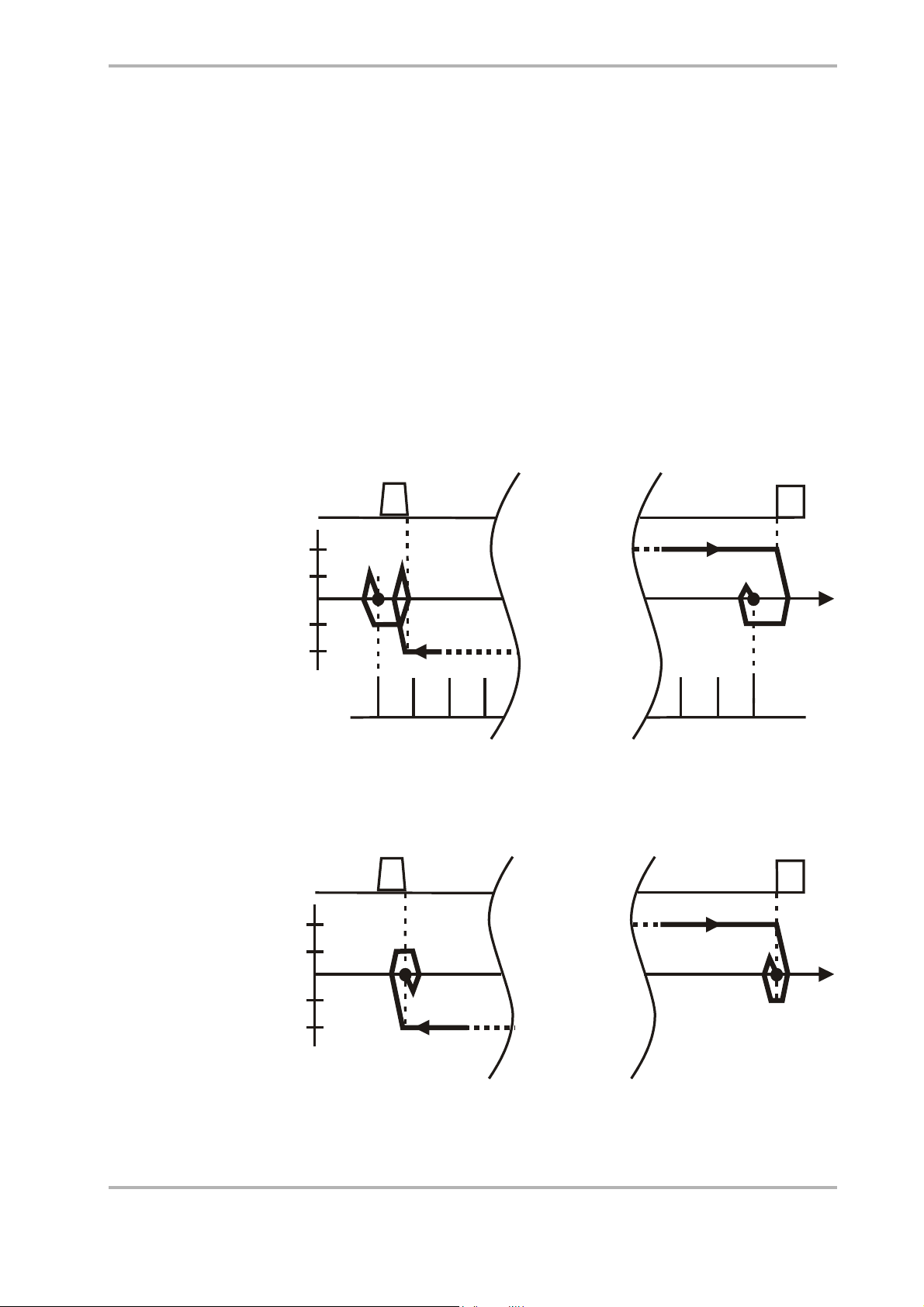
6.12.1 Positive direction
Die Achse wird durch die automatische Referenzfahrt immer so bewegt, dass die
Referenzpunktsuche immer von der negativen Seite des Referenzschalters
durchgeführt wird.
Jetter AG 29

6 Referencing JetWeb
S
Starting from the positive side of the reference switch
– The axis will start by "Speed switch search" in positive direction.
– When the positive limit switch has been recognized, the axis will reverse and
continue in negative direction by "Speed switch search".
– The axis will cross the reference switch, until the "Reference switch deactivated"
flank has been recognized.
– There, the axis will reverse again to drive in positive direction by "Speed reference
search".
– The reference position is set to the first zero pulse after having recognized the
"Reference switch active" flank again. For referencing without zero pulse ("zero
mark"), the reference position is set to the position of the "Reference switch
active" flank.
+V
+V
- V
- V
ZM
ref
ZM
ZM
ref
N
R
SP
P
Fig. 8: Referencing by reference and limit switch in positive direction; the
rotatory direction is positive; with zero pulse ("zero mark"), the starting
position is on the positive side of the reference switch.
Starting from the negative side of the reference switch
– The axis will start in positive direction by "Speed switch search".
– When the reference switch active flank has been recognized, the axis will drive
back in negative direction by "Speed switch search", until it reaches the position,
where the reference switch active flank has been recognized.
– There, the axis will reverse again to drive in positive direction by "Speed reference
search".
– The reference position is set to the first zero pulse after having recognized the
"Reference switch active" flank again. For referencing without zero pulse ("zero
mark"), the reference position is set to the position of the "Reference switch
active" flank.
30 Jetter AG

JetMove 2xx at the NANO System Bus 6.12 Referencing by Means of Reference and Limit
S
S
R
+V
+V
- V
- V
N
SP
ref
ZM
ZM
ref
ZM
Fig. 9: Referencing by reference and limit switch in positive direction; the
rotatory direction is positive; with zero pulse ("zero mark"), the starting
position is on the negative side of the reference switch.
Starting on the reference switch
– The axis will start in negative direction by "Speed switch search".
– When the reference switch has become deactivated, the axis will reverse and
continue in positive direction by "Speed reference search".
– The reference position is set to the first zero pulse after having recognized the
"Reference switch active" flank again. For referencing without zero pulse ("zero
mark"), the reference position is set to the position of the "Reference switch
active" flank.
P
R
SP
+V
+V
- V
- V
N
ref
ZM
ZM
ref
ZM
Fig. 10: Referencing by reference and limit switch in positive direction; the
rotatory direction is positive; with zero pulse ("zero mark"), the starting
position is on the reference switch.
P
Jetter AG 31

6 Referencing JetWeb
S
6.12.2 Negative direction
During automatic referencing, the axis will always be moved so that reference search
is being carried out from the positive side of the reference switch.
Starting from the positive side of the reference switch
– The axis will start in negative direction by "Speed switch search".
– When the reference switch active flank has been recognized, the axis will drive
back in positive direction by "Speed switch search", until it reaches the position,
where the "Reference switch active" flank has been recognized.
– There, the axis will reverse again to drive in negative direction by "Speed
reference search".
– The reference position is set to the first zero pulse after having recognized the
"Reference switch active" flank again. For referencing without zero pulse ("zero
mark"), the reference position is set to the position of the "Reference switch
active" flank.
N
+V
ref
+V
ZM
- V
ZM
- V
ref
ZM
Fig. 11: Referencing by reference and limit switch in negative direction; the
rotatory direction is positive; with zero pulse ("zero mark"), the starting
position is on the positive side of the reference switch.
R
SP
P
Starting from the negative side of the reference switch
– The axis will start in negative direction by "Speed switch search".
– When the negative limit switch has been recognized, the axis will reverse and
continue in positive direction by "Speed switch search".
– The axis will cross the reference switch, until the "Reference switch deactivated"
flank has been recognized.
– There, the axis will reverse again to drive in negative direction by "Speed
reference search".
– The reference position is set to the first zero pulse after having recognized the
"Reference switch active" flank again. For referencing without zero pulse ("zero
mark"), the reference position is set to the position of the "Reference switch
active" flank.
32 Jetter AG

JetMove 2xx at the NANO System Bus 6.12 Referencing by Means of Reference and Limit
S
S
R
+V
+V
- V
- V
N
SP
ref
ZM
ZM
ref
ZM
Fig. 12: Referencing by reference and limit switch in negative direction; the
rotatory direction is positive; with zero pulse ("zero mark"), the starting
position is on the negative side of the reference switch.
Starting on the reference switch
– The axis will start in positive direction by "Speed switch search".
– When the reference switch has become deactivated, the axis will reverse and
continue in negative direction by "Speed reference search".
– The reference position is set to the first zero pulse after having recognized the
"Reference switch active" flank again. For referencing without zero pulse ("zero
mark"), the reference position is set to the position of the "Reference switch
active" flank.
P
R
SP
+V
+V
- V
- V
N
ref
ZM
ZM
ref
ZM
Fig. 13: Referencing by reference and limit switch in negative direction; the
rotatory direction is positive; with zero pulse ("zero mark"), the starting
position is on the reference switch.
P
Jetter AG 33

6 Referencing JetWeb
S
S
6.13 Referencing by only One Limit Switch
If the limit switch has been found when driving in referencing direction, the axis will
be referenced there.
The limit switch being positioned in negative direction will be ignored, until the axis
has reversed on the limit switch positioned in positive direction. When the axis has
reversed and the limit switch being positioned in the new direction has been
recognized, the axis will be stopped and an error will be output in register 170
"Positioning Error" (bit 18 "Reference: Limit switch positive" or bit 19 "Reference:
Limit switch negative").
Starting in positive direction
P
+V
+V
- V
- V
N
SP
ref
ZM
ZM
ref
ZM
Fig. 14: Referencing by limit switch only; positive direction, positive rotatory
direction, starting position preceeding the positive limit switch.
P
SP
+V
+V
- V
- V
N
ref
ZM
ZM
ref
ZM
Fig. 15: Referencing by limit switch only; positive direction, positive rotatory
direction, starting position on the positive limit switch.
34 Jetter AG

JetMove 2xx at the NANO System Bus 6.14 Referencing by Reference Switch Only
S
S
Starting in negative direction
P
+V
+V
- V
- V
N
SP
ref
ZM
ZM
ref
ZM
Fig. 16: Referencing by limit switch only; negative direction, positive rotatory
direction, starting position preceeding the negative limit switch.
P
+V
+V
- V
- V
N
SP
ref
ZM
ZM
ref
ZM
Fig. 17: Referencing by limit switch only; negative direction, positive rotatory
direction, starting position on the negative limit switch.
6.14 Referencing by Reference Switch
Only
The axis drives to the reference switch to be referenced there. When, during the
reference run, the limit switch being positioned in the referencing direction has been
recognized, the axis will be stopped and an error will be output in register 170
"Positioning Error" (bit 18 "Reference: Limit switch positive" or bit 19 "Reference:
Limit switch negative"). The limit switch being positioned in negative direction will be
ignored.
This type of referencing is used with a conveyor belt, for example, which is to be reset
to zero after each turnover.
For the sequence of motions, please refer to chapter 6.12 "Referencing by Means of
Reference and Limit Switch", page 29.
Jetter AG 35

6 Referencing JetWeb
36 Jetter AG

JetMove 2xx at the NANO System Bus 7.1 Endless Positioning
7 Positioning
7.1 Endless Positioning
Attention!
Endless positioning is only allowed, if the axis is set to modulo mode.
Transition can be made from endless positioning to Ptp-positioning. Yet, it is not
possible to make transition from a running Ptp-positioning endless positioning.
Command 57 "Reversing of an endless positioning" will not consider the changes in
the positioning parameters, such as speed, which have been made after starting the
endless positioning.
Jetter AG 37

7 Positioning JetWeb
38 Jetter AG

JetMove 2xx at the NANO System Bus
8 Oscilloscope Function
The following registers can be used for oscilloscope recording in JetSym both as
recording and as trigger parameters:
• Register 109 "Actual position"
• Register 111 "Set speed value"
• Register 112 "Actual motor speed"
• Register 119 "Actual tracking error"
• Register 125 "Set current value"
• Register 129 "Actual mechanic speed"
• Register 130 "Set position value"
• Register 560 "DC link voltage"
• Register 561 "Actual current value"
• Register 562 "Motor temperature"
• Register 563 "Device temperature"
• Register 564 "Ballast workload"
• Register 565 "Motor shaft position"
• Register 566 "Device input current"
• Register 567 "Supply voltage"
• Register 568 "Controller card temperature"
Jetter AG 39

8 Oscilloscope Function JetWeb
40 Jetter AG

JetMove 2xx at the NANO System Bus 9.1 Control Parameters
9 Register Description
9.1 Control Parameters
Register 101: Command
Function Description
Read Latest command
Write Issuing a new command
Amplifier status No specific status
Validity Wait for the busy-bit in the status to be reset
Value range 0 ... 32.767
Value after reset 0
ATTENTION:
When a command has been issued, the PLC program cannot make another access
to the amplifier, unless the busy-bit in the status register has been reset by the
amplifier.
Commands:
The following commands are available:
1 Activating the output stage
2 Deactivating the output stage
3 Set the reference (actual position = the target position has been set, also
considering the tracking error)
5 Stop positioning by the maximum deceleration rate that is permitted (see
R180)
6 Stop positioning by the deceleration ramp (R106)
7 Stopping an axis motion by the emergency stop ramp (R549)
ATTENTION:
When the ramp has been covered, the output stage will automatically be
deactivated.
8 Acknowledging an error
9 Search for reference
10 Starting an absolute positioning run
11 Starting an absolute positioning run related to time
12 Changing an absolute target position
Jetter AG 41

9 Register Description JetWeb
The following commands are available:
13 Changing a speed value
15 Changing an acceleration value
16 Changing a deceleration value
20 Starting a relative positioning run
22 Changing a relative target position
32 Starting the setup mode
33 Stopping the setup mode
(The stop will not be made unless the next target position has been
reached)
56 Starting an endless positioning run
ATTENTION:
Endless positioning is only allowed, if the axis is set to modulo mode.
The direction of rotation is defined via register 142.
57 Reversing an endless positioning run
PLEASE NOTE:
Command 57 is used in order to reverse an endless positioning run that
has already been started. This means that the actual motion direction
will be reversed.
Register 515: Dig. outputs - switch status
Function Description
Read Value of the actual switch status
Write New value of the switch status
Amplifier status No specific status
Validity Immediately
Value range bit-coded, 24 bits
Value after reset 0
This only applies to JetMove 215/208
By means of this register, the status of the outputs can be queried, while other
outputs can be set and reset.
Meaning of the values:
0 : The output has been / will be reset
1 : The output has been set / will be reset
42 Jetter AG

JetMove 2xx at the NANO System Bus 9.1 Control Parameters
Meaning of the individual bits:
Bit 0: Output 1
Bit 1: Output 2
Bit 2: Output 3
Bit 3: Output 4
Register 516: Dig. registers for setting outputs
Function Description
Read Value set last
Write New set value
Value range bit-coded, 24 bits
Value after reset 0
This only applies to JetMove 215/208
By means of this register, only outputs can be set. If only individual outputs are to be
set, this register will make faster setting of outputs possible than if register 515 were
used.
Meaning of the values:
0 : The output will not be affected
1 : The output is set
Meaning of the individual bits:
Bit 0: Output 1
Bit 1: Output 2
Bit 2: Output 3
Bit 3: Output 4
Jetter AG 43

9 Register Description JetWeb
Register 517: Dig. outputs are reset by this register
Function Description
Read Latest reset value
Write New reset value
Value range bit-coded, 24 bits
Value after reset 0
This only applies to JetMove 215/208
By means of this register, only outputs can be reset. If only individual outputs are to
be reset, this register will make faster resetting of outputs possible than if register 515
were used.
Meaning of the values:
0 : The output will not be affected
1 : The output will be reset
Meaning of the individual bits:
Bit 0: Output 1
Bit 1: Output 2
Bit 2: Output 3
Bit 3: Output 4
Register 540: Operating mode
Function Description
Read Present state value of drive mode 1
Write New state value of drive mode 1
Amplifier status The amplifier must be deactivated
Validity Immediately
Value range bit-coded, 16 bits
Value after reset 0b 00000010 1001x011
44 Jetter AG

JetMove 2xx at the NANO System Bus 9.1 Control Parameters
ATTENTION:
If JetMove 2xx is used together with a NANO-CPU, bit 9 must always be set. The bit
has been set by default. In order to prevent important bits from being reset
unintentionally, we recommend to set, respectively reset, the bits one by one.
Meaning of the individual bits:
Bit 0: Automatic control of the brake by means of the amplifier
0 = Manual control by the user (via register 574, bit 0)
1 = Automatic control by the amplifier
Value after reset: 1
Bit 1: Automatic control of the ventilator placed in the amplifier
0 = The ventilator is always switched on
1 = Depending on the respective temperature, the ventilator will
automatically be switched off or switched on
Value after reset: 1
Bit 2: Reserved
Bit 3: Phase monitoring
Here, the decision is made, whether, in 3-phase-mode, phase monitoring
is to be activated or not. If phase monitoring has been activated, yet not
all three phases are pending, error message F02 will be output.
0 = Phase monitoring has been deactivated
1 = Phase monitoring has been activated
Value after reset for JetMove 215: 1
Value after reset for JetMove 203, 206: 0
Bit 4: Motor cable test
Here, a decision is made, whether the motor cable test is to be carried out
or not. Switching off might be necessary in case of long motor cables.
When the motor cable test has been activated, and if a ground fault of the
motor or a motor cable break have been detected, error message F03 will
be output.
0 = Motor cable test has been deactivated
1 = Motor cable test has been activated
Value after reset: 1
Bit 5: Speed reversal
By means of this bit, for all axis motions (position, speed and current
control), the direction of rotation will be conversed.
ATTENTION:
Please mind correct assignment of the hardware limit switches
Jetter AG 45
9 Register Description JetWeb
Meaning of the individual bits:
0 = Positive direction of rotation (clockwise rotation of the motor shaft,
looking at the shaft from the A-side; the set values are positive)
1 = Negative direction of rotation (counterclockwise rotation of the motor
shaft, looking at the shaft from the A-side; the set values are positive)
Value after reset: 0 (Positive direction of rotation)
Bit 6: Software limit switch
0 = The software limit switch evaluation has been deactivated
1 = The software limit switch evaluation has been activated
Value after reset: 0
Bit 7: Hardware limit switch
0 = The hardware limit switch evaluation has been deactivated
1 = The hardware limit switch evaluation has been activated
Value after reset: 1
Bit 8: Reserved
Bit 9: JetMove 2xx at the NANO / ConMove
ATTENTION:
If JetMove 2xx is used together with a NANO-CPU, this bit must always
be set.
0 = JetMove 2xx at ConMove
1 = JetMove 2xx at NANO
Value after reset: 1
46 Jetter AG

JetMove 2xx at the NANO System Bus 9.1 Control Parameters
Register 541: Operating mode of the 7-segment
display
Function Description
Read Number of the actual operating mode
Write New number of the operating mode
Value range 0 ... 1
Value after reset 0
See JetMove 2xx operator's manual
Meaning of the values:
0 : Normal operation
1 : Installation
Register 572: Set operating mode
Function Description
Read Number of the presently set operating mode
Write Number of the newly set operating mode
Amplifier status The amplifier must be deactivated
Validity When the amplifier is activated again
Value range 101, 102, 103
Value after reset 103
Here, the operating mode is set, in which the controller is to be run.
Meaning of the values:
101 : Current control (only the current control is active)
A set current value can be input via register 125
102 : Speed control (current control and speed control are active)
A set speed value can be input via register 111
103 : Position control (current control, speed control and position control
are active)
Jetter AG 47

9 Register Description JetWeb
Register 573: Actual mode of operation
Function Description
Read Value of the actual operating mode
Write Illegal
Value range 100 ... 103
Value after reset 100
Here, the actual operating mode the controller had when the output stage was
switched on last, can be read.
Meaning of the values:
100 : The output stage has not been activated yet
101 : Current control (only the current control is active)
102 : Speed control (current control and speed control are active)
103 : Position control (current control, speed control and position control
are active)
Register 574: Control word 2
Function Description
Read Value of the actual control word
Write New value of the control word
Value range bit-coded, 24 bits
Value after reset 0
Meaning of the individual bits:
Bit 0: Manual control of the brake
0 = Lock the brake
1 = Release the brake
(A requirement for manual control: In register 540 "Operating mode 1", bit
0 must be set to "Manual operation by the user".)
48 Jetter AG

JetMove 2xx at the NANO System Bus 9.1 Control Parameters
Register 575: Status word 2
Function Description
Read Value of the actual status word
Write Illegal
Value range bit-coded, 24 bits
Value after reset 0
Meaning of the individual bits:
Bit 0: Brake
0 = The brake is locked / the relay contacts have been released
1 = The brake has been released / the relay contacts are locked
Jetter AG 49

9 Register Description JetWeb
9.2 Diagnose Parameters
Register 100: Status
Function Description
Read Present status
Write Illegal
Value range bit-coded, 24 bits
Value after reset 0
From here, the amplifier status can be read. It contains information on the most
important amplifier parameters.
Meaning of the individual bits:
Bit 0: RefOK
Bit 1: Stopped
Bit 2: Destination window
Bit 3: -
Bit 4: Hardware limit switch negative
Bit 5: Hardware limit switch negative
Bit 6: Reference switch
Bit 7: Software limit switch, negative
Bit 8: Software limit switch, positive
Bit 9: -
Bit 10: The power section is ready for operation
Bit 11: Power has been released
Bit 12: Setup mode active
Bit 13: Busy bit:
(For all commands, register 180, register 181, register 184)
Bit 14: The maximum positioning speed has been reached (the axis has driven
beyond the range of the ramps)
Bit 15: Acceleration ramp
Bit 16: Deceleration ramp
Bit 17: -
Bit 18: There is an error or warning
50 Jetter AG

JetMove 2xx at the NANO System Bus 9.2 Diagnose Parameters
Meaning of the individual bits:
Bit 19: Errors
Bit 20: Danger
Bit 21: The pulse has been released (hardware release)
Register 170: Error referencing / positioning
Function Description
Read Actual errors
Write Illegal
Value range bit-coded, 24 bits
Value after reset 0
Actual errors can be read here during referencing or positioning.
Attention!
A number of these errors will NOT be shown on the display of the JetMove 2xx.
Meaning of the individual bits:
Bit 16: Referencing: Max. distance reference search
The permitted maximum distance of reference search has been
exceeded. The distance can be set via register 167 "Max. distance
reference search".
Bit 17: Referencing: Max. distance switch search
The permitted maximum distance of switch search has been exceeded.
The distance can be set via register 164 "Max. distance switch search".
Bit 18: Referencing: Positive limit switch
Reference switch type consisting of reference and limit switch:
The positive limit switch has been found after changing direction at the
negative limit switch during a reference run in negative direction.
Reference switch type, with limit switch only:
The positive limit switch has been found after changing direction at the
negative limit switch during a reference run in negative direction.
Reference switch type, with reference switch only:
The positive limit switch has been found during a reference run in
positive direction.
Jetter AG 51

9 Register Description JetWeb
Meaning of the individual bits:
Bit 19: Referencing: Negative limit switch
Reference switch type consisting of reference and limit switch:
The negative limit switch has been found after changing the direction at
the positive limit switch during a reference run in positive direction.
Reference switch type, with limit switch only:
The negative limit switch has been found after changing direction at the
positive limit switch during a reference run in positive direction.
Reference switch type, with reference switch only:
The negative limit switch has been found during a reference run in
negative direction.
Register 580: Warnings mask
Function Description
Read Actual warnings mask
Write New warnings mask
(this can only be changed with an expert's access
authorization, see register 576)
Value range bit-coded, 24 bits
Value after reset 0b 00000000 00000000 00111111
In the warnings mask, a definition can be made of which warnings are to be displayed
and which are not. The assignment of bits can be taken out of the description of
register 581 "Warnings".
Meaning of the values:
0 : The warning will not be displayed
1 : The warning will be displayed
52 Jetter AG

JetMove 2xx at the NANO System Bus 9.2 Diagnose Parameters
Register 581: Warnings
Function Description
Read Actual Warnings
Write Warnings are reset
Value range bit-coded, 24 bits
Value after reset 0
Meaning of the individual bits:
Bit 0: W00 Warning threshold for ballast
Bit 1: W01 Warning threshold for device temp.
Bit 2: W02 Warning threshold for motor temp.
Bit 3: W03 Overload PFC
Bit 4: W04 Input overcurrent
Bit 5: W05 Warning threshold for board temp.
Register 582: AutoClear mask for warnings
Function Description
Read Actual AutoClear mask
Write New AutoClear mask
Value range bit-coded, 24 bits
Value after reset 0b 00000000 00000000 00111111
Definitions to be made via AutoClear mask:
• Which warnings are to be automatically reset by the amplifier itself, as soon as
they are not relevant any more
• Which warnings are to be manually reset by the user
Manual resetting is carried out by writing into the respective bit in register 581
"Warnings". The assignment of bits can be taken out of the description of register 581
"Warnings".
Meaning of the values:
0 : The warning will automatically be reset by the user
1 : The warning will automatically be reset by the amplifier
Jetter AG 53

9 Register Description JetWeb
Register 585: Error 0 ... 15
Function Description
Read Actual errors numbered 00 through 15
Write Illegal
Value range bit-coded, 16 bits
Value after reset 0
Meaning of the individual bits:
Bit 0: F00 Hardware error
Bit 1: F01 Internal voltage supply error
Bit 2: F02 One mains phase has failed
Bit 3: F03 Motor or cable fault
Bit 4: F04 DC link overvoltage U
Bit 5: F05 Current overload
Bit 6: F06 Overload internal ballast resistor
Bit 7: F07 Shutdown threshold for device temp.
Bit 8: F08 Shutdown threshold for motor temp.
Bit 9: F09 Encoder error
Bit 10: F10 Overspeed
Bit 11: F11 Current overrange
Bit 12: F12 Earth fault
Bit 13: F13 AVR EEPROM failure
Bit 14: F14 AVR timeout
Bit 15: F15 Pulse enable failure
ZK
54 Jetter AG

JetMove 2xx at the NANO System Bus 9.2 Diagnose Parameters
Register 586: Error 16 ... 31
Function Description
Read Actual errors numbered 16 through 31
Write Illegal
Value range bit-coded, 16 bits
Value after reset 0
Meaning of the individual bits:
Bit 0: F16 Input overcurrent
Bit 1: F17 Software limit switch
Bit 2: F18 Limit switch hardware error
Referencing: The same hardware limit switch is pressed twice within a
short time.
Bit 3: F19 Timeout ext. error reaction Errors
Bit 4: F20 U
Bit 5: F21 U
Bit 6: F22 Drive blocked
Bit 7: F23 Tracking error
Bit 8: F24 Power supply 24 V failure
Bit 9: F25 Power supply 15 V failure
Bit 10: F26 Power supply 5 V failure
Bit 11: F27 Power supply AVR failure
Bit 12: F28 Error in power charging circuit (this is only possible with JetMove
215)
, DC link voltage min. trip
ZK
, DC link voltage max. trip
ZK
Jetter AG 55

9 Register Description JetWeb
9.3 Positioning Parameters
Register 102: Target position
Function Description
Read Actual target position
Write New target position
Amplifier status No specific status
Validity At the next positioning run or at command 12
Value range R183 ... R182 [°] or [mm]. The unit depends on
the setting of the axis type. The value contains an
adjustable decimal factor between 1 and 1,000;
this means that the least significant decimal
positions serve as decimal positions when the
internal unit [°] or [mm] is assigned to the value.
Value after reset 0 [°]
Here, the target position for the next point-to-point positioning is specified. Here, the
point-to-point positioning can be either absolute or relative. The register can be
written into during a positioning run.
The target position is used at the following commands:
• Command 10 "Starting an absolute positioning run"
• Command 11 "Starting an absolute positioning run related to time"
• Command 12 "Changing an absolute target position"
• Command 20 "Starting a relative positioning run"
• Command 22 "Changing a relative target position"
Attention!
Positioning is not started yet by writing into the target position. Only the
respective command will cause the positioning run to be started.
The target position of a positioning run that is already in process can be changed. In
order to change the target position, the new target position must be written into the
register; then, one of the following commands must be issued:
56 Jetter AG

JetMove 2xx at the NANO System Bus 9.3 Positioning Parameters
Point-to-point positioning - absolute
• Command 10 "Starting an absolute positioning run"
The entire positioning will be calculated again. New general conditions can
change the behaviour, e.g. speed, of the new positioning run compared to the
former one.
• Command 11 "Starting an absolute positioning run related to time"
The entire positioning will be calculated again. New general conditions can
change the behaviour, e.g. speed, of the new positioning run compared to the
former one.
• Command 12 "Changing an absolute target position"
Positioning will only be newly calculated regarding the new target position. New
general conditions will not be considered; speed, for example, remains
unchanged.
Point-to-point positioning - relative
• Command 20 "Starting a relative positioning run"
The entire positioning will be calculated again. New general conditions can
change the behaviour, e.g. speed, of the new positioning run compared to the
former one.
• Command 22 "Changing a relative target position"
Positioning will only be newly calculated regarding the new target position. New
general conditions will not be considered; speed, for example, remains
unchanged.
Leading over from endless to point-to-point positioning:
• Command 10 "Starting an absolute positioning run"
The entire positioning will be calculated again.
Yet, it is not possible for a running point-to-point positioning to be led to endless
positioning.
Jetter AG 57

9 Register Description JetWeb
Register 103: Target speed
Function Description
Read Actual target speed
Write New target speed
Amplifier status No specific status
Validity At the next positioning run or at command 13
Value range 0 ... R184 [°/s] or [mm/s]
(The unit is dependent on the axis type)
Value after reset 0 [°/s]
Here, the target speed for all positioning runs, point-to-point positioning and endless
positioning is specified. The register can be written into during a positioning run.
The target speed is used at the following commands:
• Command 10 "Starting an absolute positioning run"
• Command 13 "Changing a speed"
• Command 20 "Starting a relative positioning run"
• Command 56 "Starting endless positioning"
Attention!
If, during a positioning run, a register is written into, the new target speed will not
be of any effect, unless the respective command has been issued.
The target speed of a positioning run that is already in process can be changed. For
this purpose, the new target speed must be written into the register, and command
13 "Changing a speed" must be issued.
Changing a target speed value is also considered, when, during a positioning run
already in process, the following commands are given:
• Command 10 "Starting an absolute positioning run"
• Command 20 "Starting a relative positioning run"
• Command 56 "Starting endless positioning"
This is only permitted, if the running positioning is an endless positioning; during
a running point-to-point positioning, this command must not be issued.
58 Jetter AG

JetMove 2xx at the NANO System Bus 9.3 Positioning Parameters
Register 104: Positioning time
Function Description
Read Actual positioning time
Write New (set) positioning time
Amplifier status No specific status
Validity Next positioning started by command 11
Value range 0 ... 32,767 [s]
Value after reset 0 [s]
Instead of issuing a speed via register 103, it is also possible to set a time for pointto-point positioning. Then, the speed will result from the actual position, the target
position, the content of register 2, and the time set for this.
The amplifier will enter the calculated speed into register 103 "Target Speed"; it will
be used at the following positioning run, if the contents of register 103 are not
changed.
Positioning related to time is started by issuing command 11 "Starting an absolute
positioning run related to time".
The target speed of a positioning run that is already in process can be changed. For
this purpose, the new positioning time must be entered into the register and
command 11 must be issued. It is insignificant, whether the positioning running at
that moment has been started by issuing command 11 or not. Please mind, though,
that the speed of the new positioning run can be different from the former one.
A positioning run started by command 11 can be influenced and altered by changing
the positioning parameters and by issuing the respective commands.
Jetter AG 59

9 Register Description JetWeb
Register 105: Acceleration
Function Description
Read Actual acceleration
Write Set acceleration
Amplifier status No specific status
Validity At the next positioning run or at command 15
Value range 0 ... R180 [°/s²] or [mm/s²]
(The unit is dependent on the axis type)
Value after reset 500 [°/s²]
Here, the acceleration for individual positioning runs is specified. The acceleration
value is used for starting a positioning run and for the change of speed during a
positioning run. This means that, even if, during positioning, the speed is being
decelerated, still the acceleration value is used for this deceleration. The
deceleration value of register 106 will only be used for deceleration when driving
towards the target position and for carrying out command 6 "Stop positioning (user
ramp)".
The target speed is used at the following commands:
• Command 10 "Starting an absolute positioning run"
• Command 11 "Starting an absolute positioning run related to time"
• Command 15 "Changing an acceleration value"
• Command 20 "Starting a relative positioning run"
• Command 56 "Starting endless positioning"
Attention!
A low value results in a long ramp, while a great value results in a short ramp.
Two ramp types can be selected for acceleration:
• sine-square ramp (sine-square shaped speed profile)
or
• linear ramp (linear speed profile)
The ramp type can be selected by means of register 140 "Ramp type". The sinesquare ramp has been set as the default ramp type.
A sine-square ramp guarantees a soft and jerk-free start. When driving a sine-square
ramp, the specified value will be reached in the middle of the acceleration process.
If a linear ramp is driven, acceleration will remain constant; the speed will increase
in linear mode during the entire acceleration process.
60 Jetter AG

JetMove 2xx at the NANO System Bus 9.3 Positioning Parameters
In the illustration below, various settings for acceleration by sine-square ramp will be
shown.
v in 1/min
6,000
The set acceleration value
is reached here
0
1,000 3,000
2,000
4,000
t in ms
Fig. 18: Acceleration process
The acceleration rate of a positioning run that is already in process can be changed.
For this purpose, the new acceleration rate must be written into the register, and
command 15 "Changing a speed" must be issued. Yet, this change will not take effect
on the actual acceleration ramp, but on the ramp that is to follow.
Changing an acceleration value is also considered, when, during a positioning run
already in process, the following commands are given:
• Command 10 "Starting an absolute positioning run"
• Command 11 "Starting an absolute positioning run"
• Command 20 "Starting a relative positioning run"
• Command 56 "Starting endless positioning"
This is only permitted, if the running positioning is an endless positioning; during
a running point-to-point positioning, this command must not be issued.
Jetter AG 61

9 Register Description JetWeb
Register 106: Deceleration
Function Description
Read Actual delay
Write Set delay
Amplifier status No specific status
Validity At the next positioning run or at command 16
Value range 0 ... R180 [°/s²] or [mm/s²]
(The unit is dependent on the axis type)
Value after reset 500 [°/s²]
Here, the deceleration rate when driving towards the target for positioning runs is
specified. The deceleration value will only be used for driving towards the target
position and for carrying out command 6 "Stop positioning (user ramp)". For a
change of speed during positioning, the acceleration value specified in register 105
will be used. This means that, even if, during positioning, the speed is being
decelerated, still the acceleration value is used for this deceleration.
The deceleration for driving towards the target is used at the following commands:
• Command 6 "Stop positioning (user ramp)"
• Command 10 "Starting an absolute positioning run"
• Command 11 "Starting an absolute positioning run related to time"
• Command 16 "Changing a deceleration value"
• Command 20 "Starting a relative positioning run"
Attention!
A low value results in a long ramp, while a great value results in a short ramp.
Two ramp types can be selected for deceleration when driving towards the target:
• sine-square ramp (sine-square shaped deceleration profile)
or
• linear ramp (sine-square shaped speed profile)
The ramp type can be selected by means of register 140 "Ramp type". The sinesquare ramp has been set as the default ramp type.
A sine-square ramp guarantees soft and jerk-free deceleration. When driving a sinesquare ramp, the specified value will be reached in the middle of the deceleration
process.
62 Jetter AG

JetMove 2xx at the NANO System Bus 9.3 Positioning Parameters
When driving a linear ramp, the deceleration when driving towards the target (not the
deceleration profile) has got a sine-square-shaped speed profile. This way, soft and
jerk-free deceleration will be guaranteed as well. When driving a sine-square ramp,
the specified value will also be reached in the middle of the deceleration process.
In the illustration below, various settings for deceleration by sine-square ramp when
driving towards the target will be shown.
v in 1/min
6,000
The set deceleration value
will be reached here
0
0
1,000
2,000
3,000
4,000
t in ms
Fig. 19: Deceleration process when driving towards the target
Register 107: Destination window
Function Description
Read Present destination window
Write New destination window
Amplifier status No specific status
Validity At the next positioning run or after changing the
target position
Value range 0 ... 8,388,607 [°] or [mm] (the unit is dependent
on the settings of the axis type. The value
contains an adjustable decimal factor between 1
and 1,000; this means that the least significant
decimal positions serve as decimal positions
when the internal unit [°] or [mm] is assigned to
the value.
Value after reset 1 [°]
Here, the destination window for the target area of a point-to-point positioning can be
set. If , after positioning, the axis has reached the destination window, bit 2
"Destination window" will be set in register 100 "Status". The bit will not be reset,
unless a new positioning (point-to-point positioning) has been started.
Jetter AG 63

9 Register Description JetWeb
Destination window 5 mm around
destination position 100 mm
95
100
105
s in mm
Fig. 20: Example of a destination window
Attention!
If a point-to-point positioning is stopped before the axis has reached the
destination window, the destination window bit will not be set. In this case, bit 1
"Stopped" can be used in register 100 "Status".
Faster program flow can be achieved by using the destination window range. The
program can be continued, as soon as the axis has reached the destination window.
The general progression condition would be as follows:
...
REGISTER_LOAD (rmTargetPosition, 90000) // Target position 90000
// (° or mm)
REGISTER_LOAD (rmCommand, 10) // Start ptp positioning
WHEN BIT_CLEAR (rmStatus, 13) THEN // Wait, until busy-bit
// has been reset
WHEN BIT_SET (rmStatus, 2) THEN // Wait, till dest. wind. bit
// has been set
...
Difference between destination window bit and "Stopped" bit
The destination window bit is set, as soon as the actual position of the axis has
reached the destination window. The "Stopped" bit will be set, as soon as the internal
set position (not the actual position) has reached the target position. The settings of
the destination window take no effect on the "Stopped" bit.
64 Jetter AG

JetMove 2xx at the NANO System Bus 9.3 Positioning Parameters
Register 109: Actual position
Function Description
Read Actual position
Write Illegal
Value range R183 ... R182 [°] or [mm] (The unit depends on
the setting of the axis type. The value contains an
adjustable decimal factor between 1 and 1,000;
this means that the least significant decimal
positions serve as decimal positions when the
internal unit [°] or [mm] is assigned to the value.
Value after reset 0 [°]
From here, the actual axis position can be read out. This parameter is often used as
a progression condition.
Example:
...
WHEN REG rmActPosition > 10000 THEN // Wait, until the actual
// pos. is greater than 10000
// (° or mm)
OUT 101 // Set output 101
...
If the axis has not been set to modulo mode in register 192 "Modulo axis", the actual
position will not exceed the travel range, which has been set via register 182 "Travel
range limit positive" and register 183 "Travel range limit negative". Neither will there
be an overflow. At the limits of the travel range, the axis will be stopped automatically.
Endless positioning is not permitted here.
If the axis has been set to modulo mode in register 192 "Modulo axis", there will be
an overflow of the actual position, when the travel range limits have been exceeded;
the actual position will be continued at the value of the other travel range limit. The
axis will continue travelling as before. Endless positioning is only permitted for a
modulo axis.
Jetter AG 65

9 Register Description JetWeb
Register 129: Actual speed
Function Description
Read Actual mechanical speed
Write Illegal
Value range -R184 ... R184 [°/s] or [mm/s]
(The unit is dependent on the axis type)
Value after reset 0 [°/s]
From here, the actual axis speed can be read out.
Register 131: Setup mode - delay
Function Description
Read Present delay value
Write New delay value
Amplifier status No specific status
Validity Immediately
Value range 1 ... 65,535 [ms]
Value after reset 1,000 [ms]
Here, the delay time for setup mode will be specified. The delay time is the duration
of waiting at every target position in setup mode, until the next point-to-point
positioning towards the other target position is started.
66 Jetter AG

JetMove 2xx at the NANO System Bus 9.3 Positioning Parameters
Register 132: Setup mode - position 1
Function Description
Read Actual position 1
Write New position 1
Amplifier status No specific status
Validity At the next start into the direction of position 1
Value range R183 ... R133 [°] or [mm] (The unit depends on
the setting of the axis type. The value contains an
adjustable decimal factor between 1 and 1,000;
this means that the least significant decimal
positions serve as decimal positions when the
internal unit [°] or [mm] is assigned to the value.
Value after reset 0 [°]
Here, position 1 (left position) is specified for the setup mode.
Register 133: Setup mode - position 2
Function Description
Read Actual position 2
Write New position 2
Amplifier status No specific status
Validity At the next start into the direction of position 2
Value range R132 ... R182 [°] or [mm] (The unit depends on
the setting of the axis type. The value contains an
adjustable decimal factor between 1 and 1,000;
this means that the least significant decimal
positions serve as decimal positions when the
internal unit [°] or [mm] is assigned to the value.
Value after reset 100 [°]
Here, position 2 (right position) is specified for the setup mode.
Jetter AG 67

9 Register Description JetWeb
Register 140: Accel / decel ramp type
Function Description
Read Actual ramp type
Write New ramp type
Amplifier status No specific status
Validity At the next positioning run
Value range 0, 1
Value after reset 1
Here, the ramp type will be set for all positioning runs. The ramp type will only be
considered when a new positioning run is started; then, it will be valid during the
entire positioning process.
Meaning of the values:
0 : Linear ramps
1 : Sine-square ramps
Register 141: Positioning mode
Function Description
Read Actual positioning mode
Write New positioning mode
Amplifier status No specific status
Validity At the next positioning run or after changing the
target position
Value range 1 ... 4
Value after reset 1
The following only applies to modulo axis:
Here it is specified, from which direction the target position is to be approached.
Meaning of the values:
1:Absolute
The axis will never exceed the travel range; it can be operated and
positioned like a standard axis
2:Modulo positive
68 Jetter AG

JetMove 2xx at the NANO System Bus 9.3 Positioning Parameters
The axis will always approach the target position from positive
direction
3:Modulo negative
The axis will always approach the target position from negative
direction
4:Modulo auto
The axis will always approach the target position over the shortest
possible distance
Register 142: Motion direction
Function Description
Read Actual direction of movement
Write New direction of movement
Amplifier status No specific status
Validity When the next endless positioning is started
Value range 0, 1
Value after reset 0
This only applies to an endless positioning run:
Here, the direction of movement is specified for an endless positioning run.
Meaning of the values:
0 : positive direction
1 : negative direction
Jetter AG 69

9 Register Description JetWeb
Register 143: Basic type
Function Description
Read Actual basic type
Write New basic type
Amplifier status No specific status
Validity When the next relative positioning run is started,
or when the target position of a relative
positioning is changed
Value range 0, 1
Value after reset 0
This only applies to relative positioning:
Here, the basic position (the position, in relation to which values are counted further)
is specified for the next relative positioning run.
Meaning of the values:
0 : Latest target position
1 : Actual position
70 Jetter AG

JetMove 2xx at the NANO System Bus 9.4 Referencing - Parameters
9.4 Referencing - Parameters
Register 160: Direction of referencing
Function Description
Read Actual direction of referencing
Write New direction of referencing
Amplifier status No specific status
Validity Next referencing
Value range 0, 1
Value after reset 0
Here, the direction of referencing will be specified. Referencing will then be started
by issuing command 9.
Meaning of the values:
0 : Positive direction
1 : Negative direction
For this, please also read chapter 6 "Referencing", page 23.
Register 161: Switch type
Function Description
Read Actual switch type
Write New switch type
Amplifier status No specific status
Validity Next referencing
Value range 0 ... 3
Value after reset 1
Here it is specified, which hardware switches are to be used for referencing.
Meaning of the values:
0 : No switches, only zero pulse of the encoder
1 : Reference and limit switches
2 : Only limit switches
Jetter AG 71

9 Register Description JetWeb
3 : Only reference switches
For this, please also read chapter 6 "Referencing", page 23.
Register 162: Speed switch search
Function Description
Read Actual search speed
Write New search speed
Amplifier status No specific status
Validity Next referencing
Value range 0 ... R184 [°/s] or [mm/s] (the unit depends on the
setting of the axis type)
Value after reset 500 [°/s]
Here the speed is specified, by which the axis starts referencing by switch search.
When the switch has been found, the "reference mark" will be searched for. For
searching the "reference mark", a specific speed will be set in register 166 "Speed
reference search".
Which switch is to be used for referencing (reference switch, limit switch, zero pulse)
is defined in register 161 "Switch".
For this, please also read chapter 6 "Referencing", page 23.
72 Jetter AG

JetMove 2xx at the NANO System Bus 9.4 Referencing - Parameters
Register 163: Acceleration at referencing
Function Description
Read Actual acceleration
Write Set acceleration
Amplifier status No specific status
Validity Next referencing
Value range 0 ... R180 [°/s²] or [mm/s²] (the unit depends on
the settings of the axis type)
Value after reset 1,000 [°/s²]
Here, the acceleration for referencing is specified. This acceleration value applies to
starting and stopping the reference run and to changes of speed. The changes of
speed result from various speed settings for the switch search, see register 162
"Speed switch search", and to the search for the "reference mark", see register 166
"Speed reference search".
Attention!
If referencing has been interrupted by issuing command 6, the axis will be brought
to a standstill by the deceleration defined in register 106 "Deceleration".
For this, please also read chapter 6 "Referencing", page 23.
Register 164: Max. distance switch search
Function Description
Read Actual maximum distance
Write New maximum distance
Amplifier status No specific status
Validity Next referencing
Value range -8,388,708 ... 8,388,607 [°] or [mm] (the unit is
dependent on the settings of the axis type. The
value contains an adjustable decimal factor
between 1 and 1,000; this means that the least
significant decimal positions serve as decimal
positions when the internal unit [°] or [mm] is
assigned to the value.
Value after reset 100,000 [°]
Jetter AG 73

9 Register Description JetWeb
Hier wird der maximale Weg angegeben, innerhalb der das Auftreten des
Schaltersignals erfolgen muss. The distance will be measured from the starting
position of the reference run. If the maximum distance is exceeded, the axis will be
stopped and the error "Max. distance switch search" of bit 17 in register 170 "Error
positioning" will be output.
For this, please also read chapter 6 "Referencing", page 23.
Register 165: Reference mark
Function Description
Read Actual reference mark
Write New reference mark
Amplifier status No specific status
Validity Next referencing
Value range 1, 2
Value after reset 1
Meaning of the values:
1 : Referencing by means of zero pulse
2 : Referencing without zero pulse (this means the reference position
will only be the switch flank of the reference switch, respectively of
the limit switch)
For this, please also read chapter 6 "Referencing", page 23.
Register 166: Speed reference search
Function Description
Read Actual search speed
Write New search speed
Amplifier status No specific status
Validity Next referencing
Value range 0 ... R184 [°/s] or [mm/s] (the unit depends on the
setting of the axis type)
Value after reset 100 [°/s]
74 Jetter AG

JetMove 2xx at the NANO System Bus 9.4 Referencing - Parameters
Here, the speed will be specified, by which the axis approaches the reference
position. When the switch signal has been recognized, the reference position will be
searched for. The reference position can either be the position of the zero pulse
("zero mark") or the position of the switch flank, if referencing is being carried out
without zero pulse.
The switch is searched for by the speed, which has been set in register 162 "Speed
of switch search".
For this, please also read chapter 6 "Referencing", page 23.
Register 167: Max. distance reference search
Function Description
Read Actual max. distance reference search
Write New max. distance reference search
Amplifier status No specific status
Validity Next referencing
Value range -8,388,608 ... 8,388,607 [°] or [mm] (the unit is
dependent on the settings of the axis type. The
value contains an adjustable decimal factor
between 1 and 1,000; this means that the least
significant decimal positions serve as decimal
positions when the internal unit [°] or [mm] is
assigned to the value.
Value after reset 1,000 [°]
Within this maximum distance, the reference mark must be active. The distance will
be measured from the starting position of the reference search. If the maximum
distance is exceeded, the axis will be stopped and the error "Max. distance reference
search" of bit 17 in register 170 "Error positioning" will be output.
For this, please also read chapter 6 "Referencing", page 23.
Jetter AG 75

9 Register Description JetWeb
Register 168: Normal position: distance
Function Description
Read Actual acceleration
Write Set acceleration
Amplifier status No specific status
Validity Next referencing
Value range -8,388,608 ... 8,388,607 [°] or [mm] (the unit is
dependent on the settings of the axis type. The
value contains an adjustable decimal factor
between 1 and 1,000; this means that the least
significant decimal positions serve as decimal
positions when the internal unit [°] or [mm] is
assigned to the value.
Value after reset 0 [°]
Here, the distance between the virtual normal position and the found reference
position is specified. After a successfully completed reference run, the axis is to
come to a standstill at the so-called normal position. By "distance", the space is
specified, which the axis, after having got to the reference position, must still cover
in order to reach "normal position".
For this, please also read chapter 6 "Referencing", page 23.
Register 169: Normal position
Function Description
Read Present virtual position
Write New virtual position
Amplifier status No specific status
Validity Next referencing
Value range -8,388,608 ... 8,388,607 [°] or [mm] (the unit is
dependent on the settings of the axis type. The
value contains an adjustable decimal factor
between 1 and 1,000; this means that the least
significant decimal positions serve as decimal
positions when the internal unit [°] or [mm] is
assigned to the value.
Value after reset 0 [°]
Here, the position is specified, which, at "normal position" is to be set in register 109
as virtual position.
76 Jetter AG

JetMove 2xx at the NANO System Bus 9.5 Axis Parameters
After a successfully completed reference run, the axis comes to a standstill at the socalled "normal position". For this, please also refer to the description of register 168
"Normal position: distance".
Please also read chapter 6 "Referencing", page 23.
9.5 Axis Parameters
Register 114: Software limit positive
Function Description
Read Present value of the virtual software limit switch
Write New value of the software limit switch
Amplifier status The amplifier must be deactivated
Validity Immediately
Value range -8,388,608 ... 8,388,607 [°] or [mm] (the unit is
dependent on the settings of the axis type. The
value contains an adjustable decimal factor
between 1 and 1,000; this means that the least
significant decimal positions serve as decimal
positions when the internal unit [°] or [mm] is
assigned to the value.
Value after reset 100,000 [°]
This parameter contains the position at which the software limit switch in positive
direction becomes active. When the limit switch is activated, the axis will be stopped
and error F17 will be displayed. Further, bit 8 is set in register 100 "Status".
The software limit switch monitoring can be activated, respectively deactivated, via
register 540 "Operating mode 1", bit 6. The software limit switch monitoring should
be active in any case, though, especially when axes are driven in manual mode.
Attention!
The software limit switch monitoring is deactivated by default.
Jetter AG 77

9 Register Description JetWeb
The following figure shows the positions of the software limit switches:
Emergency
Stop
Hardware
Limit Switch
Software
Limit Switch
Register
1x115
Reference
Switch
Travel Range
Negative
Travelling
Direction
Emergency
Stop
Mechanical
End Stop
“0”
Reference
Position
Fig. 21: Position of the software limit switches
Register 115: Software limit negative
Function Description
Software
Limit Switch
Register
1x114
Travelling
Direction
Hardware
Limit Switch
Positive
Emergency
Stop
Emergency
Stop
Mechanical
End Stop
Read Present value of the virtual software limit switch
Write New value of the software limit switch
Amplifier status The amplifier must be deactivated
Validity Immediately
Value range -8.388,608 ... 8,388,607 [°] or [mm] (the unit is
dependent on the settings of the axis type. The
value contains an adjustable decimal factor
between 1 and 1,000; this means that the least
significant decimal positions serve as decimal
positions when the internal unit [°] or [mm] is
assigned to the value.
Value after reset -100,000 [°]
This parameter contains the position at which the software limit switch in negative
direction becomes active. When the limit switch is activated, the axis will be stopped
and error F17 will be displayed. Further, bit 7 is set in register 100 "Status".
The software limit switch monitoring can be activated, respectively deactivated, via
register 540 "Operating mode 1", bit 6. The software limit switch monitoring should
be active in any case, though, especially when axes are driven in manual mode.
78 Jetter AG

JetMove 2xx at the NANO System Bus 9.5 Axis Parameters
Attention!
The software limit switch monitoring is deactivated by default.
The figure regarding register 114 "Position of the software limit switch" illustrates the
positions of the respective software limit switches.
Register 180: Maximum acceleration
Function Description
Read Actual acceleration value
Write New acceleration value
Amplifier status The amplifier must be deactivated
Validity Wait for the busy-bit in the status to be reset
Value range 0 ... 8,388,607 [°/s²] or [mm/s²] (the unit depends
on the settings of the axis type)
Value after reset 100,000 [°/s²]
Here, the maximum acceleration / deceleration of an axis is specifed. The amplifier
will limit each acceleration, respectively deceleration, to the specified value, even if
a greater value has been specified for positioning purposes. Acceleration /
deceleration will only be limited for positioning by means of position control.
The axis will also be decelerated according to this parameter, if you issue command
5.
Register 181: Maximum jerk
Function Description
Read Value of the actual jerk
Write New value of the jerk
Amplifier status The amplifier must be deactivated
Validity Wait for the busy-bit in the status to be reset
Value range 0 ... 8,388,607 [°/s³] or [mm/s³] (the unit depends
on the settings of the axis type)
Value after reset 1,000,000 [°/s³]
Jetter AG 79

9 Register Description JetWeb
Here, the maximum permitted jerk for the specific axis is specified. The amplifier will
limit the jerk to this value when one kind of motion follows the other one. Jerk limiting
is important, especially when linear ramps are applied. The jerk will only be limited
for positioning by means of position control.
Register 182: Travel limit positive
Function Description
Read Value of the present limit
Write New value of travel limit
Amplifier status The amplifier must be deactivated
Validity Immediately
Value range -8,388,608 ... 8,388,607 [°] or [mm] (the unit is
dependent on the settings of the axis type. The
value contains an adjustable decimal factor
between 1 and 1,000; this means that the least
significant decimal positions serve as decimal
positions when the internal unit [°] or [mm] is
assigned to the value.
Value after reset 100,000 [°]
Here, the positive modulo travel range limit of a modulo axis will be specified. The
modulo travel range defined in register 193 "Modulo travel range" will automatically
be calculated as the difference between the positive and the negative travel range.
If your axis is not a modulo axis, this parameter will limit the absolute axis motion in
positive direction. This means that, at a positioning run, the target position will always
be limited to this value, even if a higher value is entered.
Via register 192 "Modulo axis", the axis will be set to modulo axis.
80 Jetter AG

JetMove 2xx at the NANO System Bus 9.5 Axis Parameters
Register 183: Travel limit negative
Function Description
Read Value of the present limit
Write New value of travel limit
Amplifier status The amplifier must be deactivated
Validity Immediately
Value range -8,388,608 ... 8,388,607 [°] or [mm] (the unit is
dependent on the settings of the axis type. The
value contains an adjustable decimal factor
between 1 and 1,000; this means that the least
significant decimal positions serve as decimal
positions when the internal unit [°] or [mm] is
assigned to the value.
Value after reset -100,000 [°]
Here, the negative modulo travel range limit of a modulo axis will be specified. The
modulo travel range defined in register 193 "Modulo travel range" will automatically
be calculated as the difference between the positive and the negative travel range.
If your axis is not a modulo axis, this parameter will limit the absolute axis motion in
negative direction. This means that, at a positioning run, the target position will
always be limited to this value, even if a higher value is entered.
Via register 192 "Modulo axis", the axis will be set to modulo axis.
Register 184: Maximum speed
Function Description
Read Value of the actual maximum speed
Write New value of the maximum speed
Amplifier status The amplifier must be deactivated
Validity Wait for the busy-bit in the status to be reset
Value range 0 ... 8,388,607 [°/s] or [mm/s] (the unit depends
on the setting of the axis type)
Value after reset 18,000 [°/s]
Here, the maximum speed of the mechanic axis is specified. The amplifier limits the
speed to this value, even if a higher speed has been set for positioning. Further, this
value is necessary for monitoring the maximum acceleration / deceleration and the
maximum jerk.
Jetter AG 81

9 Register Description JetWeb
The greatest value that can be input here, is limited by the value in register 118
"Maximum motor speed" and by the values of the registers for setting the gearbox
factors: Register 194 "Transmission ratio - motor", register 195 "Transmission ratio mechanics, and register 196 "Transmission ratio - linear / rotatory".
The value must not be greater than the result of the following formula:
greatest value R184 = R118 * R196 * R195 / (R194 * 60)
Register 191: Axis type
Function Description
Read Actual value of the virtual axis type
Write New value of the virtual axis type
Amplifier status The amplifier must be deactivated
Validity Immediately
Value range 1, 2
Value after reset 2 (rotatory)
Here, the motion of the axis is defined: either linear or rotatory.
Meaning of the values:
1 : Linear
2 : Rotatory
Usually, a machine consists of two kinds of axes:
• Linear axes
• Rotatory axes
In case of a linear axis, the load is moved in linear direction; all positioning
parameters have been specified in the [mm] unit. In case of a rotatory axis, the load
will be moved on a circular path; for this reason, all positioning parameters have been
specified in the [°] unit.
These are the positioning parameters:
• Positioning parameter
• Speed parameter
• Acceleration / Deceleration parameter
• Parameter for jerk limitation
The units for a linear axis shown in detail:
• Unit defining a position: [mm]
• Unit defining speed: [mm/s]
82 Jetter AG

JetMove 2xx at the NANO System Bus 9.5 Axis Parameters
• Unit defining acceleration / deceleration: [mm/s²]
• Unit defining jerk: [mm/s³]
The units for a rotatory axis shown in detail:
• Unit defining a position: [°]
• Unit defining speed: [°/s]
• Unit defining acceleration / deceleration: [°/s²]
• Unit defining jerk: [°/s³]
If in register 192 "Modulo axis" the axis type is set to modulo axis, a linear axis cannot
be selected out of this register.
Register 192: Modulo axis
Function Description
Read Present setting
Write New value
Amplifier status The amplifier must be deactivated
Validity Immediately
Value range 0, 1
Value after reset 0
Here it is defined, whether the axis is a modulo axis or not.
Meaning of the values:
0 : No modulo axis
1 : Modulo axis
What is a modulo axis?
The positioning values of a modulo axis are always within a defined modulo travel
range (in order to make possible endless positioning, for example), see register 193
"Modulo travel range".
If the axis moves in positive direction and reaches the positive travel limit, the
position will be set back to the value of the negative travel limit. This means the axis
can continue with new positioning values starting from the negative travel range.
If the axis moves in negative direction and reaches the negative travel limit, the
position will be set back to the value of the positive travel limit. This means the axis
can continue with new positioning values starting from the positive travel range.
Consequently, modulo axis haven't got any hardware or software limit switches.
Jetter AG 83

9 Register Description JetWeb
The following figure will illustrate an endless axis motion in positive direction by a
modulo travel range of 200,000 ° (negative travel limit = 0 °, positive travel limit =
200,000 °).
Position
200,000
150,000
100,000
50,000
0
Positioning cycle 1
Positioning cycle 2
Positioning cycle 3
Fig. 22: Example of a modulo axis motion
Register 193: Modulo travel range
Function Description
Read Actual value of the virtual travel range
Write Illegal
Value range -8,388,608 ... 8,388,607 [°] or [mm] (the unit is
dependent on the settings of the axis type. The
value contains an adjustable decimal factor
between 1 and 1,000; this means that the least
significant decimal positions serve as decimal
positions when the internal unit [°] or [mm] is
assigned to the value).
Value after reset 360 [°]
Time t
The modulo travel range will automatically be calculated as the difference between
the positive travel range, register 182, and the negative travel range, register 183.
Attention!
If no modulo axis has been set in register 192, the modulo mode is deactivated;
this means that the value of this register is not valid and will thus not be calculated
as the difference between the values of the travel ranges.
84 Jetter AG

JetMove 2xx at the NANO System Bus 9.5 Axis Parameters
Register 194: Transmission ratio - motor
Function Description
Read Actual number of motor revolutions
Write New number of motor revolutions
Amplifier status The amplifier must be deactivated
Validity Immediately
Value range 1 ... 8,388,607 [rev]
Value after reset 1 [rev]
In case of a rotatory axis, the following parameter will be used for calculating the gear
ratio:
i
If, for example, the mechanics rotate once, while the motor rotates ten times, the
number of motor revolutions must also be set to 10, while the number of load
revolutions is set to 1.
In case of a linear axis, the gear ratio, and the additional parameter "Transmission
ratio - linear / rotatory" written in register 196, must be specified. "Transmission ratio
linear / rotatory" defines the transition from rotatory to linear mode.
Number of motor revolutions (R194)
--------------------------------------------------------------------------------------------------------------- -=
Number of mechanics/load revolutions (R195)
Jetter AG 85

9 Register Description JetWeb
Register 195: Transmission ratio - mechanics
Function Description
Read Actual number of load revolutions
Write New number of load revolutions
Amplifier status The amplifier must be deactivated
Validity Immediately
Value range 1 ... 8,388,607 [rev]
Value after reset 1 [rev]
Here, the latest rotatory transmission unit must be specified; see description of
register 194 "Transmission ratio - motor".
Register 196: Transmission ratio - linear / rotatory
Function Description
Read Actual transmission ratio
Write New transmission ratio
Amplifier status The amplifier must be deactivated
Validity Immediately
Value range 1 ... 8,388,607 [° * 1,000/Umdr.] or [µm/rev.]
Value after reset 360,000 [°*1,000/rev]
The transmission ratio linear /rotatory is only needed for a linear axis; it describes the
linear motion of the axis related to a rotation of the latest rotatory transmission unit
written in register 195 "Transmission ratio - mechanics".
The parameters "Transmission ratio - mechanics", register 195, and "Transmission
ratio - motor", register 194, must also be specified.
86 Jetter AG

JetMove 2xx at the NANO System Bus 9.5 Axis Parameters
Register 510: Dig. Inputs: Input polarity
Function Description
Read Value of the actual input polarity
Write New value of the input polarity
Amplifier status The amplifier must be deactivated
Validity Immediately
Value range bit-coded, 16 bits
Value after reset 0b 00000001 00001111
Here, the polarity of the digital inputs can be specified.
Meaning of the values:
0:0 V active
1 : 24 V active
Meaning of the individual bits:
Bit 0: Enable (cannot be altered)
Bit 1: Positive hardware limit switch
Bit 2: Negative hardware limit switch
Bit 3: Reference switch
Bit 8: Interrupt (special applications)
Register 511: Dig. Inputs: Input circuit state
Function Description
Read Value of the actual input circuit state
Write Illegal
Value range bit-coded, 16 bits
Value after reset 0
The actual input circuit state of the digital inputs can be read out here. The input
circuit state depends on the polarity settings of the digital inputs specified in register
1x510.
Jetter AG 87

9 Register Description JetWeb
Meaning of the values:
0:Not active
1 : Activated
Meaning of the individual bits:
Bit 0: Enable (cannot be altered)
Bit 1: Positive hardware limit switch
Bit 2: Negative hardware limit switch
Bit 3: Reference switch
Bit 8: Interrupt (special applications)
Register 870: Decimal places for position values
Function Description
Read Values of the actual decimal positions
Write New values of the decimal positions
Amplifier status The amplifier must be deactivated
Validity Immediately
Value range 0 ... 3
Value after reset 0
Here, the decimal positions for all positioning parameters will be set. This should be
done during axis setup and not be changed after this any more.
0 = No decimal positions
The position values contain a decimal factor of 1, which means that the internal unit
[°] or [mm] will directly be displayed and written.
1 = 1 decimal position
The position values contain a decimal factor of 10, which means that the least
significant decimal position of the integer value is the decimal position for
standardizing the value to have the internal unit [°] or [mm].
2 = 2 decimal positions
The position values contain a decimal factor of 100, which means that the two least
significant decimal positions of the integer value are the decimal positions for
standardizing the value to have the internal unit [°] or [mm].
88 Jetter AG

JetMove 2xx at the NANO System Bus 9.5 Axis Parameters
3 = 3 decimal positions
The position values contain a decimal factor of 1,000, which means that the three
least significant decimal positions of the integer value are the decimal positions for
standardizing the value to have the internal unit [°] or [mm].
Attention!
If decimal positions are altered after setup of the axis, there might occur the
danger of position details not being displayed correctly. This could happen, if a
parameter of 0 decimal positions, for example, already causes 8,000,000 to be
displayed. If the decimal positions are increased then, a negative value will be
displayed, as the maximum positive limit of the value range, which is 8,388,607,
will have been exceeded.
The settings of the decimal positions relate to the following registers:
• Register 102 "Target position"
• Register 107 "Destination window"
• Register 109 "Actual position"
• Register 114 "Pos. software limit switch"
• Register 115 "Neg. software limit switch"
• Register 119 "Actual tracking error"
• Register 120 "Tracking error limit"
• Register 130 "Set position value"
• Register 132 "Setup mode - position 1"
• Register 133 "Setup mode - position 2"
• Register 164 "Max. distance switch search"
• Register 167 "Max. distance reference search"
• Register 168 "Normal position - distance"
• Register 169 "Normal position"
• Register 182 "Travel limit positive"
• Register 183 "Travel limit negative"
• Register 193 "Modulo travel range"
Jetter AG 89

9 Register Description JetWeb
9.6 Amplifier Parameters
Register 199: Software version
Function Description
Read Value of the latest version
Write Illegal
Value range 0 ... 9,999
Value after reset Dependent on the software version
Here, the latest software version can be read. Interpreting the value:
290 = Version 2.90
Attention!
When submitting technical support queries the number of the software version
must be quoted.
In connection with register 999 "Revision status of the operating system", it can be
specified, whether the software version is a beta version or not.
Register 500: Rated voltage
Function Description
Read Value of the actual rated voltage
Write Illegal
Value range 230 ... 400 [V]
Value after reset Dependent on the amplifier type (particulars can
be found on the identification plate of the
respective device)
From here, the rated voltage of the device can be read out.
90 Jetter AG

JetMove 2xx at the NANO System Bus 9.6 Amplifier Parameters
Register 501: Rated current
Function Description
Read Value of the actual rated voltage of the device
Write Illegal
Value range 300 ... 1,500 [Aeff*100]
(The respective value contains a decimal factor
of 100, which means that the two least significant
decimal positions of the integer value are the
decimal positions for standardizing the value to
have the internal unit [Aeff]).
Value after reset Dependent on the amplifier type (particulars can
be found on the identification plate of the
respective device)
From here, the continuous rated current of the device can be read out.
Register 508: PWM frequency
Function Description
Read Value of the actual PWM frequency
Write New value of the PWM frequency
Amplifier status The amplifier must be deactivated
Validity Immediately
Value range 8, 16 [kHz]
Value after reset 16 [kHz] for JetMove 203-206
8 [kHz] for JetMove 215
Here, the frequency of the output pulse can be altered.
Attention!
Only instructed personnel is to make alterations on the register value.
Jetter AG 91

9 Register Description JetWeb
Register 560: DC link voltage
Function Description
Read Actual DC link voltage
Write Illegal
Value range 0 ... 640 [V]
Value after reset 0 [V]
Here, the latest DC link voltage can be read.
Register 563: Temperature
Function Description
Read Actual value of the device temperature
Write Illegal
Value range 1 ... 95 [°C]
Value after reset 0 [°C]
Here, the actual internal temperature of the device can be read.
Register 564: Ballast load, internal
Function Description
Read Actual value of the ballast load
Write Illegal
Value range 0 ... 100 [%]
Value after reset 0 [%]
Here, the actual load of the internal ballast resistor can be read.
92 Jetter AG

JetMove 2xx at the NANO System Bus 9.6 Amplifier Parameters
Register 566: Input current of the device
Function Description
Read Actual input current
Write Illegal
Value range 0 ... 2,550 [Aeff*100] (The value has got a
decimal factor of 100, which meanst that the two
least significant decimal positions of the integer
value are the decimal positions for standardizing
the value to have the internal unit [Aeff])
Value after reset 0 [Aeff*100]
The actual input current value of the supply feed can be read out here.
Register 567: Mains voltage
Function Description
Read Actual mains voltage
Write Illegal
Value range 0 ... 460 [Veff]
Value after reset 0 [Veff]
The actual input current value of the supply feed can be read out here.
Register 568: Temperature
Function Description
Read Actual value of the board temperature
Write Illegal
Value range 20 ... 75 [°C]
Value after reset 0 [°C]
Here, the actual temperature of the controller board can be read.
Jetter AG 93

9 Register Description JetWeb
Register 576: Interface access authorization
Function Description
Read Actual access authorization
Write Specify new access authorization
Amplifier status The amplifier must be deactivated
Validity Immediately
Value range 0 ... 65,535
Value after reset 0
In this register, access authorization for the register interface is defined. There are
two kinds of access authorization:
0 = Standard user access authorization
1 = Expert user access authorization
In order to specify expert user access authorization, a respective code must be
written into this register. If a new user access authorization has been specified
successfully, the respective number, as quoted above, will be read out. Certain
registers can only be modified, if the user has got the expert access authorization. If
for changing the value of a register expert user access authorization is needed, this
will be pointed out in the register description.
Assigning access authorization is a safety precaution for the protection of persons
and assets.
Register 999: The revision state of the operating
system
Function Description
Read Value of the actual revision state
Write Illegal
Value range 0 ... 9,999
Value after reset Dependent on the revision state
From here, the new number of the operating system software revision can be read
out. Interpreting the value:
0 = The revision has been released officially
1 ... 9,999 = Beta revision 1 ... 9,999
94 Jetter AG

JetMove 2xx at the NANO System Bus 9.7 Motor Parameters
9.7 Motor Parameters
Register 116: Commutation offset
Function Description
Read Value of the actual offset
Write New value of the offset
Amplifier status The amplifier must be deactivated
Validity Immediately
Value range -18,000 ... 18,000 [°*100] (The value has got a
decimal factor of 100, which means that the two
least significant decimal positions of the integer
value are the decimal positions for standardizing
the value to have the internal unit [°])
Value after reset 0 [°*100]
Here, the commutating offset of the motor will be specified. This machine parameter
has been reserved for special applications. If required, the parameter is defined by
the manufacturer.
Register 117: Encoder resolution
Function Description
Read Value of the present resolution
Write Illegal
Value range 4,096 ... 32,768 [Incr./rev.]
Value after reset Dependent on the connected encoder
This register specifies the internal resolution of a revolution in increments per
revolution. This value is dependent on the connected encoder. See register 577
"Encoder type"
Jetter AG 95

9 Register Description JetWeb
Register 123: Pole pair number
Function Description
Read Actual pole pair number
Write New pole pair number
Amplifier status The amplifier must be deactivated
Validity Immediately
Value range 1 ... 12
Value after reset 3
Here, the pole pair number of the motor is entered. This can be taken from the motor
parameters. For Jetter motors, the pole pair number usually is 3. This is also the
default value.
Register 505: Motor voltage constant
Function Description
Read Value of the actual voltage constant
Write New value of the voltage constant
Amplifier status The amplifier must be deactivated
Validity Immediately
Value range 0 ... 120 [V*min/1,000]
Value after reset 0 [V*min/1,000]
Here, the voltage constant of the motor is entered. The value of the voltage constant
can be taken from the motor parameters.
The voltage constant of the Jetter motor has also been specified on the nameplate:
Jetter motors of the type JL3-300-25-3 have got a voltage constant of 25 V*min/
1,000.
If highly dynamic drives are used, this parameter should be adjusted.
96 Jetter AG

JetMove 2xx at the NANO System Bus 9.7 Motor Parameters
Register 547: Delay after release brake
Function Description
Read Actual delay time
Write New delay time
Amplifier status The amplifier must be deactivated
Validity Immediately
Value range 0 ... 65,535 [ms]
Value after reset 0 [ms]
Only for motors equipped with a brake. Here, the delay time is specified which
passes (after issuing a command, e.g. command 1 "Activate output stage"), until the
brake has really been released. When this time has passed, the brake is in the
"Brake has been released" state. Not before this time has expired, the axis will be
controlled. The delay time can differ between various manufacturers or motor types.
Attention!
The predefined value of this parameter may only be altered by experienced users.
The following commands have an impact on releasing the brake:
• Issuing command 1 - The brake is released.
• Setting bit 0 in register 574 "Control word 2" - brake is released.
Jetter AG 97

9 Register Description JetWeb
Delay time at releasing the brake
0 ms (default setting)
1
Release
control
To rq u e
Brake
Force
(at the brake)
0
releasing
locking
Delay time at locking the brake
100 ms (default setting)
Fig. 23: Delay time of the motor brake control
Register 548: Delay after locking the brake
Function Description
Read Actual delay time
Write New delay time
Amplifier status The amplifier must be deactivated
Validity Immediately
Value range 0 ... 65,535 [ms]
Value after reset 100 [ms]
Only for motors equipped with a brake:
t
Here, the delay time is specified which passes (after issuing a command, e.g.
command 2 "Deactivate output stage"), until the brake has really been locked. When
this time has passed, the brake is in the "Brake has been locked" state.
Up to then, the axis will still be controlled.
The delay time can differ between various manufacturers or motor types.
The following commands have an impact on locking the brake:
• Issuing command 2 - The brake is locked
• Resetting bit 0 in register 574 "Control word 2" - the brake is locked
98 Jetter AG

JetMove 2xx at the NANO System Bus 9.7 Motor Parameters
Please also see the time diagram in the manual referring to register 547 "Delay time
at releasing the motor brake".
Register 562: Temperature
Function Description
Read Actual motor temperature
Write Illegal
Value range 1 ... 155 [°C]
Value after reset 0 [°C]
If a motor with temperature switch is used, 1 °C is displayed for the "locked" state,
while 155 °C is displayed for the "released" state.
Jetter AG 99

9 Register Description JetWeb
/+180
Register 565: Shaft position
Function Description
Read Actual position of the shaft
Write Illegal
Value range -18,000 ... 18,000 [°*100] (The value has got a
decimal factor of 100, which means that the two
least significant decimal positions of the integer
value are the decimal positions for standardizing
the value to have the internal unit [°])
Value after reset 0 [°*100]
The present position of the motor shaft can be read out by means of this parameter.
0°
-90°
Fig. 24: Shaft position
-
-
+
°
+90°
Register 577: Encoder type
Function Description
Read Actual encoder type
Write Illegal
Value range 1 ... 3
Value after reset Dependent on the connected encoder
By means of this parameter, the encoder type of the connected motor can be
specified:
1 = Resolver
2 = HIPERFACE SRS50 (Singleturn)
3 = HIPERFACE SRM50 (Multiturn)
100 Jetter AG
 Loading...