

60880901
User Manual
JC-120MC - Controller
We automate your success.

Introduction
Item # 60880901
Revision 1.26.2
September 2016 / Printed in Germany
This document has been compiled by Jetter AG with due diligence, and based on the known state of the art.
In the case of modifications, further developments or enhancements to products shipped in the past, a revised document
will be supplied only if required by law, or deemed appropriate by Jetter AG. Jetter AG shall not be liable for errors in form
or content, or for missing updates, as well as for damages or disadvantages resulting from such failure.
The logos, brand names, and product names mentioned in this document are trademarks or registered trademarks of
Jetter AG, of associated companies or other title owners and must not be used without consent of the respective title
owner.
2 Jetter AG

JC-120MC Introduction
Address
Assignment to product
How to contact us:
Jetter AG
Graeterstrasse 2
71642 Ludwigsburg
Germany
Phone - Switchboard: +49 7141 2550-0
Phone - Sales: +49 7141 2550-433
Phone - Technical Hotline: +49 7141 2550-444
Fax - Sales: +49 7141 2550-484
E-mail - Sales: sales@jetter.de
E-mail - Technical Hotline: hotline@jetter.de
This User Manual is an integral part of JC-120MC:
Type:
Serial #:
Year of manufacture:
Order #:
To be entered by the customer:
Inventory #:
Place of operation:
Jetter AG 3

Introduction
Significance of this
User Manual
This document is an integral part of the JC-120MC:
Keep this document in a way that it is always at hand until the JC-120MC
will be disposed of.
Pass this document on if the JC-120MC is sold or loaned/leased out.
In any case you encounter difficulties to clearly understand the contents of this
document, please contact Jetter AG.
We would appreciate any suggestions and contributions on your part and
would ask you to contact us at the following e-mail address: info@jetter.de.
Your feedback will help us produce manuals that are more user-friendly, as
well as address your wishes and requirements.
This document contains important information on the following topics:
Transport
Mounting
Installation
Programming
Operation
Maintenance
Repair
Therefore, you must carefully read, understand and observe this document,
and especially the safety instructions.
In the case of missing or inadequate knowledge of this document Jetter AG
shall be exempted from any liability. Therefore, the operating company is
recommended to obtain the persons' confirmation that they have read and
understood this manual in writing.
4 Jetter AG

JC-120MC Contents
Table of Contents
1 Safety instructions 13
Basic safety instructions .............................................................................................................. 14
Instructions on EMI ...................................................................................................................... 16
2 Product description and design 19
Product description of the JC-120MC .......................................................................................... 20
Parts and interfaces of the controller JC-120MC ......................................................................... 21
Order reference/options ............................................................................................................... 22
List of documentation ................................................................................................................... 23
Accessories for the JX3 system ................................................................................................... 25
Physical dimensions .................................................................................................................... 26
3 Identifying 27
3.1 Identification by means of the nameplate ............................................................................... 28
Nameplate .................................................................................................................................... 29
3.2 Electronic Data Sheet EDS ........................................................................................................ 30
EDS file ........................................................................................................................................ 31
EDS registers ............................................................................................................................... 35
3.3 Version registers ........................................................................................................................ 37
Hardware revisions ...................................................................................................................... 38
Software versions ......................................................................................................................... 39
4 Mechanical and electrical installation 41
4.1 Interfaces .................................................................................................................................... 42
Power supply terminal X10 .......................................................................................................... 43
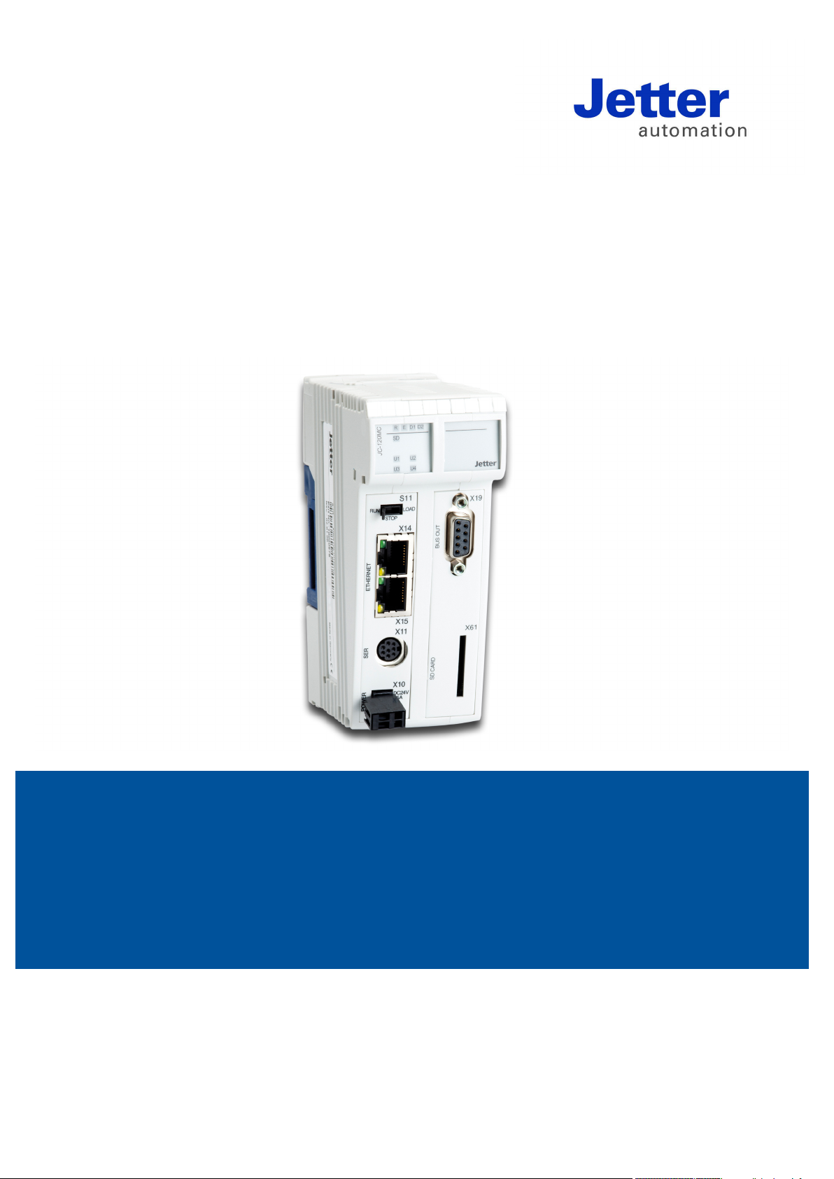
Serial interface port X11 ............................................................................................................... 44
Ethernet ports - Female connectors X14, X15 ............................................................................. 47
4.2 CAN bus interface - Female connector X19 ............................................................................ 48
Female connector X19 - Pin assignment ..................................................................................... 49
Specification of the Y cable .......................................................................................................... 51
JX2 system bus cable specification ............................................................................................. 53
Line length and baud rate of the JX2 system bus........................................................................ 55
4.3 LEDs indicating various states ................................................................................................. 56
LEDs of the controller .................................................................................................................. 57
LEDs of the controller during boot process .................................................................................. 59
LED indications on the controller after an IP address conflict has been detected....................... 61
Status LEDs - Ethernet interface .................................................................................................. 62
4.4 Controls and SD memory card ................................................................................................. 63
Function description of mode selector S11 .................................................................................. 64
SD card slot X61 .......................................................................................................................... 66
4.5 Installing, replacing and removing the module ...................................................................... 68
Installing the JC-120MC on a DIN rail .......................................................................................... 69
Replacing the controller JC-120MC ............................................................................................. 70
Removing the JC-120MC from the DIN rail ................................................................................. 72
4.6 IP configuration .......................................................................................................................... 73
Factory settings ............................................................................................................................ 74
The configuration memory ........................................................................................................... 75
Jetter AG 5

Contents
The configuration file ................................................................................................................... 76
Configuration registers ................................................................................................................ 80
Changing the IP address of the controller ................................................................................... 81
Setting the default IP address 192.168.10.15 ............................................................................. 82
Setting the IP address via configuration file ................................................................................ 83
Setting the IP address via configuration file and DIP switch ....................................................... 84
Setting the IP address via registers to be non-volatile ................................................................ 86
Setting the IP address during runtime ......................................................................................... 88
IP address in the GNN operating mode ...................................................................................... 89
Using names for IP addresses .................................................................................................... 91
4.7 Engineering of JX3 station equipped with a JC-120MC ........................................................ 93
4.7.1 Limitations to be taken into account when engineering a JX3 station ................................ 94
Limitations of the maximum number of modules......................................................................... 97
Limitations of the modules' data exchange rates ........................................................................ 98
Limitation depending on the power consumption of the modules ............................................. 101
4.8 Configuring the JX2 system bus ........................................................................................... 106
4.8.1 Wiring the JX2 system bus..................................................................................................... 107
Line length and baud rate of the JX2 system bus ..................................................................... 108
JX2 system bus topology .......................................................................................................... 109
Power supply of JX2-I/O modules .............................................................................................. 110
Power supply of JX2 slave modules .......................................................................................... 112
4.9 Connecting displays and HMIs ............................................................................................... 113
Overview of displays and HMIs .................................................................................................. 114
Connecting a display or HMI ...................................................................................................... 11 5
Connecting several displays or HMIs: Multi-display mode ......................................................... 116
Multi-display mode - Wiring ........................................................................................................ 117
Interface cable JC-DK-Xm.......................................................................................................... 119
Interface cable KAY_0386-xxxx ................................................................................................ 121
Interface cable KAY_0533-0025................................................................................................ 123
5 Initial commissioning 125
Preparatory work for initial commissioning ................................................................................ 126
Initial commissioning of a JC-120MC ........................................................................................ 127
Configuring error states ............................................................................................................. 129
Configuration in JetSym ............................................................................................................ 130
6 File system 135
6.1 Properties ................................................................................................................................. 136
Flash disk - Properties ............................................................................................................... 137
SD card - Properties .................................................................................................................. 138
6.2 User administration ................................................................................................................. 139
Administration of users .............................................................................................................. 141
As-delivered condition/Predefined users and keys ................................................................... 143
Assigning locks .......................................................................................................................... 144
Assigning names to keys/locks ................................................................................................. 146
6.3 Reviewing the flash disk capacity used ................................................................................ 148
Flash disk capacity used ........................................................................................................... 149
6.4 Operating system update and application program ............................................................ 152
6.5 Formatting and checking........................................................................................................ 153
Formatting the flash disk ........................................................................................................... 154
Formatting the SD card ............................................................................................................. 155
Checking the SD card ............................................................................................................... 156
6 Jetter AG

JC-120MC Contents
7 FTP server 157
Logon ......................................................................................................................................... 158
Example: Windows FTP client ................................................................................................... 159
8 FTP client 161
8.1 Programming ............................................................................................................................ 162
Initializing the FTP client ............................................................................................................ 163
Establishing a connection to the FTP server ............................................................................. 164
Terminating a connection ........................................................................................................... 166
Reading a file ............................................................................................................................. 167
Writing to a file ........................................................................................................................... 169
Deleting a file ............................................................................................................................. 171
Changing directories .................................................................................................................. 173
Creating a directory .................................................................................................................... 175
Deleting directories .................................................................................................................... 177
Determining the current directory............................................................................................... 179
8.2 Registers ................................................................................................................................... 181
Register numbers ....................................................................................................................... 182
Registers - Description ............................................................................................................... 183
9 HTTP server 187
9.1 Server Side Includes ................................................................................................................ 188
First entry in the HTML file ......................................................................................................... 189
Inserting real-time controller values ........................................................................................... 190
Example of an HTML page ........................................................................................................ 195
10 Programming 197
Abbreviations, module register properties and formats ............................................................. 198
10.1 Memories - Overview ............................................................................................................... 199
Operating system memory ......................................................................................................... 200
File system memory ................................................................................................................... 201
Application program memory ..................................................................................................... 202
Memory for volatile application program variables .................................................................... 203
Memory for non-volatile application program registers .............................................................. 204
Memory for non-volatile application program variables ............................................................. 205
Registers on I/O modules .......................................................................................................... 206
Memory for non-volatile registers on the backplane module ..................................................... 207
Special registers ......................................................................................................................... 208
Inputs and outputs ...................................................................................................................... 209
Flags .......................................................................................................................................... 210
10.2 Register and I/O numbers with a JC-120MC ......................................................................... 211
Registers and module registers ................................................................................................. 212
Register and I/O numbers of JX3 modules connected to a JC-120MC ..................................... 214
Register numbers of JX2 slave modules connected to the JX2 system bus ............................. 215
Registers and I/O numbers of JX2-I/O modules on the JX2 system bus .................................. 216
Register and I/O numbers of IP67-I/O modules on the JX2 system bus ................................... 217
Registers and I/O numbers of CANopen® modules on the JX2 system bus ............................ 218
Register and I/O numbers of JX3 modules connected to a JX3-BN-ETH ................................. 219
Registers and I/O numbers of JX3 nodules from the JX3-BN-ETH perspective ....................... 221
10.3 Jetter Ethernet system bus ..................................................................................................... 222
The Global Node Number .......................................................................................................... 224
Jetter AG 7

Contents
10.3.1 Acyclic data interchange ........................................................................................................ 225
Command group NetCopy() ...................................................................................................... 227
Command group NetBit() .......................................................................................................... 229
Network registers ...................................................................................................................... 230
Registers located on JX3 modules ............................................................................................ 232
Indirect addressing of remote modules ..................................................................................... 234
Addressing with variable destination window ............................................................................ 236
Register description - Acyclic data interchange ........................................................................ 238
10.3.2 Cyclic data interchange .......................................................................................................... 241
Publish/subscribe ...................................................................................................................... 243
Publish/subscribe - Registers .................................................................................................... 245
Network registers, network inputs and outputs ......................................................................... 251
10.3.3 Hardware Manager .................................................................................................................. 254
Hardware Manager .................................................................................................................... 255
10.3.4 Error handling at the Jetter Ethernet system bus ............................................................... 256
Acyclic data interchange - Error logging ................................................................................... 257
Error message during CRC computing ..................................................................................... 258
Error message on part of a subscription ................................................................................... 259
Controller evaluates errors reported by a remote network node............................................... 260
10.3.5 JetIPScan - Register description ........................................................................................... 261
Register numbers ...................................................................................................................... 262
Global status - Register description .......................................................................................... 263
Warnings and errors - Register description ............................................................................... 266
Configuration - Register description .......................................................................................... 270
10.3.6 Administrating the connections of the JetIP/TCP and STX debug server ........................ 272
Automatic termination of connections ....................................................................................... 273
Register ..................................................................................................................................... 275
10.3.7 Executing an ARP request ..................................................................................................... 276
Executing an ARP request ........................................................................................................ 277
10.3.8 JetSync blockage .................................................................................................................... 278
Description of system command registers ................................................................................ 279
Description of the JetSync blockage system commands .......................................................... 282
10.4 General system registers ....................................................................................................... 284
Description of system command registers ................................................................................ 285
Description of system commands ............................................................................................. 288
10.5 Startup delay register.............................................................................................................. 293
Setting the startup delay ............................................................................................................ 294
10.6 Real-time clock (RTC) ............................................................................................................. 295
Technical specifications ............................................................................................................. 296
Programming ............................................................................................................................. 297
10.7 Runtime registers .................................................................................................................... 304
Description of the runtime registers .......................................................................................... 305
10.8 Monitoring interface activities ............................................................................................... 307
Operating principle .................................................................................................................... 308
Programming ............................................................................................................................. 310
10.9 Controlling HMIs with alphanumeric displays ..................................................................... 312
10.9.1 Connectable HMIs ................................................................................................................... 313
Overview of displays and HMIs ................................................................................................. 314
10.9.2 Registers .................................................................................................................................. 315
Register numbers ...................................................................................................................... 316
Registers - Overview ................................................................................................................. 317
10.9.3 Configuring the screen size ................................................................................................... 319
Configuring the screen size manually ....................................................................................... 320
10.9.4 Displaying texts ....................................................................................................................... 321
STX Instructions for displaying texts ......................................................................................... 322
Device numbers ........................................................................................................................ 324
8 Jetter AG

JC-120MC Contents
Cursor position ........................................................................................................................... 326
Clearing the screen .................................................................................................................... 328
10.9.5 Displaying numerical values................................................................................................... 330
STX instruction for displaying numerical values ........................................................................ 331
Device numbers ......................................................................................................................... 332
Cursor position ........................................................................................................................... 334
Setting the length of the display field ......................................................................................... 336
Setting the sign option ............................................................................................................... 337
Setting the number of decimal places ........................................................................................ 338
Setting the format of numerical values ...................................................................................... 339
10.9.6 Entering numerical values ...................................................................................................... 340
STX instruction for the input of numerical values ...................................................................... 342
Device numbers ......................................................................................................................... 343
Cursor position ........................................................................................................................... 345
Setting the length of the input field ............................................................................................ 347
Setting the maximum number of decimal places ....................................................................... 348
Setting the suggested value ....................................................................................................... 349
Polling the number of decimal places ........................................................................................ 350
UserInput - Polling the status ..................................................................................................... 351
UserInput - Aborting the instruction............................................................................................ 352
10.9.7 Querying the keys .................................................................................................................... 353
Assigning keys ........................................................................................................................... 354
Registers of basic flag numbers ................................................................................................. 358
10.9.8 Activating/deactivating LEDs ................................................................................................. 360
Assigning LEDs .......................................................................................................................... 361
Registers of LED register numbers ............................................................................................ 362
10.9.9 Monitor functions ..................................................................................................................... 364
Overview of displays and HMIs .................................................................................................. 365
Meaning of keys in monitor function .......................................................................................... 366
Displaying and changing variables ............................................................................................ 367
Configuring the monitor function ................................................................................................ 369
10.10 Controlling printer and serial interfaces ............................................................................... 371
10.10.1 Supported serial interfaces..................................................................................................... 372
Overview - Interfaces ................................................................................................................. 373
10.10.2 Registers ................................................................................................................................... 374
Register numbers ....................................................................................................................... 375
Registers - Overview .................................................................................................................. 376
10.10.3 Module numbers - Interface modules .................................................................................... 377
Configuring module numbers ..................................................................................................... 378
10.10.4 Outputting texts ....................................................................................................................... 379
STX instructions for outputting texts .......................................................................................... 380
Device numbers ......................................................................................................................... 382
10.10.5 Outputting numerical values .................................................................................................. 383
STX instruction for outputting numerical values ........................................................................ 384
Device numbers ......................................................................................................................... 385
Setting the length of the display field ......................................................................................... 386
Setting the sign option ............................................................................................................... 387
Setting the number of decimal places ........................................................................................ 388
Setting the format of numerical values ...................................................................................... 389
10.11 JX2 system bus ........................................................................................................................ 390
Module array and module codes of connected modules ........................................................... 391
JX2 system bus - Baud rate ....................................................................................................... 394
Dummy modules on the JX2 system bus .................................................................................. 396
Monitoring intervals on the JX2 system bus .............................................................................. 397
JX2 system bus - Description of non-volatile registers .............................................................. 399
Register description of modules connected to the JX2 system bus .......................................... 403
Jetter AG 9

Contents
Register description - Error logging on the JX2 system bus ..................................................... 405
Register description - Timeout and interval times for modules on the JX2 system bus............ 408
Register description - Retry counter for JX2 system bus modules ............................................ 411
Register description - Versions of JX2 system bus drivers ....................................................... 412
10.12 JX3 system bus ....................................................................................................................... 413
Module array and module codes of connected modules .......................................................... 414
Dummy modules on the JX3 system bus .................................................................................. 416
JX3 system bus - Description of non-volatile registers ............................................................. 417
Register description - Modules detected on the JX3 system bus ............................................. 418
Register description - Error logging on the JX3 system bus ..................................................... 419
Register description - Timeout intervals on the JX3 system bus .............................................. 421
Register description - Versions of JX3 system bus drivers ....................................................... 422
10.13 E-mail ........................................................................................................................................ 423
10.13.1 Configuring the E-mail feature ............................................................................................... 424
Structure of the configuration file ............................................................................................... 425
Section [SMTP] ......................................................................................................................... 426
Section [POP3] .......................................................................................................................... 428
Section [DEFAU LT ] ................................................................................................................... 430
Configuration file - Examples .................................................................................................... 431
10.13.2 Creating e-mails ...................................................................................................................... 432
Name of the e-mail template file ............................................................................................... 433
Structure of the e-mail template file ........................................................................................... 434
Inserting real-time controller values .......................................................................................... 436
10.13.3 Sending an e-mail .................................................................................................................... 441
10.13.4 Registers .................................................................................................................................. 442
Overview of registers ................................................................................................................. 443
Registers - Description .............................................................................................................. 444
10.14 Sorting data .............................................................................................................................. 447
10.15 Modbus/TCP ............................................................................................................................ 448
10.15.1 Modbus/TCP server ................................................................................................................. 449
Addressing ................................................................................................................................ 450
Supported commands - Class 0 ................................................................................................ 452
Supported commands - Class 1 ................................................................................................ 453
Supported commands - Class 2 ................................................................................................ 454
10.15.2 Modbus/TCP client .................................................................................................................. 455
10.15.3 Modbus/TCP client with STX variables ................................................................................. 457
10.16 User-programmable serial interface ...................................................................................... 459
10.16.1 Interface ................................................................................................................................... 460
Serial interface port X11 ............................................................................................................ 461
10.16.2 Functioning principle of the user-programmable serial interface ..................................... 464
Functioning principle ................................................................................................................. 465
10.16.3 Registers .................................................................................................................................. 468
Register numbers ...................................................................................................................... 469
Registers - Description .............................................................................................................. 470
10.16.4 Programming ........................................................................................................................... 477
Configuring the interface ........................................................................................................... 478
Sending characters ................................................................................................................... 479
Sending texts ............................................................................................................................. 480
Sending values .......................................................................................................................... 481
Receiving characters ................................................................................................................. 482
Receiving values ....................................................................................................................... 483
10.17 User-programmable IP interface ............................................................................................ 484
10.17.1 Programming ........................................................................................................................... 486
Initializing the user-programmable IP interface ......................................................................... 487
Establishing a connection .......................................................................................................... 488
Sending data ............................................................................................................................. 492
10 Jetter AG

JC-120MC Contents
Receiving data ........................................................................................................................... 494
Terminating a connection ........................................................................................................... 497
10.17.2 Registers ................................................................................................................................... 498
Register numbers ....................................................................................................................... 499
Register description ................................................................................................................... 500
10.18 CANopen® STX API ................................................................................................................. 503
STX function: CanOpenInit() ...................................................................................................... 507
STX function: CanOpenSetCommand() .................................................................................... 509
STX function: CanOpenUploadSDO() ....................................................................................... 511
STX function: CanOpenDownloadSDO() ................................................................................... 514
STX function: CanOpenAddPDORx() ........................................................................................ 517
STX function: CanOpenAddPDOTx() ........................................................................................ 522
Heartbeat monitoring ................................................................................................................. 526
CANopen® object dictionary ...................................................................................................... 530
10.19 User-programmable CAN-Prim interface ............................................................................... 534
Restrictions regarding the CAN-Prim interface .......................................................................... 535
User-programmable CAN-Prim interface - Operating principle ................................................. 539
Internal processes of the CAN-Prim interface ........................................................................... 540
Register description - CAN-Prim interface ................................................................................. 541
CAN message box - Description of registers for direct access ................................................. 546
CAN message box - Description of registers for indirect access ............................................... 552
Using the CAN-Prim interface .................................................................................................... 556
Using CAN-ID masks ................................................................................................................. 559
RTR frames via CAN-Prim interface .......................................................................................... 560
11 Automatic copying of controller data 562
11. 1 Operating principle .................................................................................................................. 564
Activating the AutoCopy feature................................................................................................. 565
Executing AutoCopy commands ................................................................................................ 566
Terminating AutoCopy mode ...................................................................................................... 568
11. 2 autocopy.ini - Structure ........................................................................................................... 569
Section [OPTIONS] .................................................................................................................... 570
Command sections .................................................................................................................... 571
Example of a command file ........................................................................................................ 579
11. 3 Log file ...................................................................................................................................... 582
File contents ............................................................................................................................... 583
11. 4 Data files ................................................................................................................................... 584
File format .................................................................................................................................. 585
12 OS update 587
12.1 Updating the operating system of the controller .................................................................. 588
OS update by means of JetSym ................................................................................................ 589
Operating system update via FTP ............................................................................................. 590
Automatic OS update from an SD card ..................................................................................... 591
Operating system update from within the application program ................................................. 592
12.2 OS update of a JX module....................................................................................................... 593
OS update by means of JetSym ................................................................................................ 594
Operating system update via FTP ............................................................................................. 595
Automatic OS update from an SD card ..................................................................................... 596
Operating system update from within the application program ................................................. 597
13 Application program 599
Application program - Default path ............................................................................................ 600
Jetter AG 11

Contents
The application program is stored to the SD card ..................................................................... 601
Loading an application program ................................................................................................ 602
14 Motion Control 603
15 Quick reference - JC-120(MC) 605
Appendix 621
A: Technical specifications ......................................................................................................... 622
JC-120MC: Technical data ........................................................................................................ 623
Physical dimensions .................................................................................................................. 625
Operating parameters - Environment and mechanics .............................................................. 626
Operating parameters: Enclosure ............................................................................................. 627
DC power supply inputs and outputs ........................................................................................ 628
Shielded data and I/O lines ....................................................................................................... 629
B: Index ......................................................................................................................................... 630
12 Jetter AG

JC-120MC Safety instructions
Introduction
Contents
1 Safety instructions
This chapter informs the user of basic safety instructions. It also warns the
user of residual dangers, if there are any. Furthermore, it contains information
on EMC.
Topic Page
Basic safety instructions ............................................................................... 14
Instructions on EMI ....................................................................................... 16
Jetter AG 13

1 Safety instructions
engineering, such as industrial electronics technician.
Introduction
Intended conditions of
Usage other than
Personnel qualification
Modifications and
Basic safety instructions
This device complies with the valid safety regulations and standards.
Jetter AG attaches great importance to the safety of the users.
Of course, the user should adhere to the following regulations:
Relevant accident prevention regulations
Accepted safety rules
EC guidelines and other country-specific regulations
Usage according to the intended conditions of use implies operation in
use
intended
accordance with this User Manual.
The controller JC-120MC is used to control machinery, such as conveyors,
production machines, and handling machines.
Operate the controller JC-120MC only within the limits and conditions set forth
in the technical specifications. The operating voltage of the controller
JC-120MC is classified as SELV (Safety Extra Low Voltage). Therefore, the
JC-120MC controller is not subject to the EU Low Voltage Directive.
The device must not be used in technical systems which to a high degree
have to be fail-safe.
The JC-120MC is no safety-related part as per Machinery Directive
2006/42/EC. This device is not qualified for safety-relevant applications and
must, therefore, NOT be used to protect persons.
If you intend to operate the device at ambient conditions not being in
conformity with the permitted operating conditions, please contact Jetter AG
beforehand.
Depending on the life cycle of the product, the persons involved must possess
different qualifications. These qualifications are required to ensure proper
handling of the device in the corresponding life cycle.
Product life cycle Minimum qualification
Transport/storage:
Mounting/installation:
Commissioning/
programming:
Operation:
Decommissioning/
disposal:
Trained and instructed personnel with knowledge in
handling electrostatic sensitive components.
Specialized personnel with training in electrical
Trained and instructed experts with profound
knowledge of, and experience with, electrical/drive
engineering, such as electronics engineer for
automation technology.
Trained, instructed and assigned personnel with
knowledge in operating electronic devices.
Specialized personnel with training in electrical
engineering, such as industrial electronics technician.
For safety reasons, no modifications and changes to the device and its
alterations to the module
functions are permitted.
Any modifications to the device not expressly authorized by Jetter AG will
14 Jetter AG

JC-120MC Safety instructions
Transport
Storing
Repair and maintenance
Replacing modules
Disposal
result in a loss of any liability claims to Jetter AG.
The original parts are specifically designed for the device. Parts and
equipment from other manufacturers have not been tested by Jetter AG
and are, therefore, not released by Jetter AG.
The installation of such parts may impair the safety and the proper functioning
of the device.
Any liability on the part of Jetter AG for any damages resulting from the use of
non-original parts and equipment is excluded.
The JC-120MC contains electrostatically sensitive components which can be
damaged if not handled properly.
To exclude damages to the JC-120MC during transport, the backplane module
must be mounted to it, and it must be shipped in its original packaging, as well
as in apt protective packaging..
Use an appropriate outer packaging to protect the JC-120MC against
impact or shock.
In case of damaged packaging inspect the device for any visible damage.
Inform your freight forwarder and Jetter AG.
When storing the device observe the environmental conditions given in the
technical specification.
The operator is not allowed to repair the device. The device does not contain
any parts that could be repaired by the operator.
If the device needs repairing, please send it to Jetter AG.
When replacing the JC-120MC, class of protection IP20 is not ensured. Do not
touch any electronic components once a module housing has been removed
from the backplane module.
If you touch the EMC clip, you may damage this clip. A damaged clip may
result in lower noise immunity.
When disposing of devices, the local environmental regulations must be
complied with.
Jetter AG 15

1 Safety instructions
Noise immunity of a
Measures
Instructions on EMI
system
The noise immunity of a system is determined by the weakest component of
the system. For this reason, correct wiring and shielding of cables is of
paramount importance.
Measures for increasing EMI in electric plants:
Attach the JC-120MC to a DIN rail to EN 60715 having got the dimensions
35 x 7.5 mm.
The DIN rail must be electrically conducting and grounded by either of the
two ways:
• Directly:
The following instructions are excerpts from Application Note 016:
When male connectors are used:
• Via rear panel of the electric cabinet
Also refer to Application Note 016 EMC-compatible installation of electric
cabinets by Jetter AG.
Physically separate signal and power lines. Jetter AG recommend
spacing greater than 20 cm. Cables and lines should cross each other at
an angle of 90°.
The following line cables must be shielded:
Analog lines, data lines, motor cables coming from inverter drives (servo
output stage, frequency converter), lines between components and
interference suppressor filter, if the suppressor filter has not been placed at
the component directly.
Shield cables at both ends.
Unshielded wire ends of shielded cables should be as short as possible.
The entire shield, must, in its entire perimeter, be drawn behind the
isolation, and then be clamped under the earthed strain relief with the
greatest possible surface area.
Draw the shield, in its entire perimeter, under the shielding clamp of the
metallized connector housing (impedance shielding), respectively of the
EMC gland bushing, its greatest possible surface area being clamped
under a strain relief.
Only use metallized connectors, e.g. Sub-D with metallized housing. Make
sure that the strain relief is directly connected with the housing here as
well.
16 Jetter AG

JC-120MC Safety instructions
Downloading Application
Note 016
You can download Application Note 016 EMC-Compatible Installation of
Electric Cabinets from the Jetter AG homepage http://www.jetter.de. In order
to download Application Note 016, browse the following path: Downloads Application Notes.
Jetter AG 17


JC-120MC Product description and design
Introduction
Contents
2 Product description and design
This chapter covers the design of the device, as well as how the order
reference is made up including all options.
Topic Page
Product description of the JC-120MC .......................................................... 20
Parts and interfaces of the controller JC-120MC ......................................... 21
Order reference/options ................................................................................ 22
List of documentation.................................................................................... 23
Accessories for the JX3 system ................................................................... 25
Physical dimensions ..................................................................................... 26
Jetter AG 19

2 Product description and design
With 8 axes, the cycle time is 4 ms.
bus a maximum of 6 servo axes is supported)
2 Ethernet ports with integrated switch
Powerful programming language JetSym STX
60,000 (option -R: 120,000)
1 serial port (RS-232/422/485)
1 additional CAN port (CANopen®)
Up to 16 JX3 modules can directly be added.
Modbus/TCP
SD memory card
The controller JC-120MC
Product features
Scope of delivery
Product description of the JC-120MC
The JC-120MC is a high-end compact controller covering all areas of industrial
automation thanks to its high performance in combination with motion control.
Besides traditional controller functions, JC-120MC offers a motion control
feature which allows for programming axis groups and complex path controls.
The features of the JC-120MC are listed below:
4, 8 or an unlimited number of axes
(on the CAN bus: 16 axes max.)
With 4 axes, the cycle time is 2 ms.
Up to 12 servo axes with path control (on the CAN
Non-volatile registers:
Program/data memory: 24 MB
Either 1 JX2 system bus port or 1 CAN port
(CANopen®)
Real-time clock
The following items are included in the scope of delivery of the controller
JC-120MC:
Item no. Quantity Description
Depending on
options
60870409 1 2-pin connector, spring-cage technology
60870411 10 Terminal labels
60880619 1 Installation manual
60870410 1 Keying pins
1 Controller JC-120MC
20 Jetter AG

JC-120MC Product description and design
Parts and interfaces
Parts and interfaces of the controller JC-120MC
The controller JC-120MC features the following parts and interfaces:
Number Part Description
1
Upper latch Lets you remove the module enclosure from
the backplane module
2
X19 JX2 system bus interface and CANopen®
bus interface
3
4
5
6
7
Backplane module For installing the module on a DIN rail
X11 9 Connector for additional JX3 modules
Module enclosure
DIN rail latch For removing the JC-120MC from the DIN rail
Lower latch Lets you remove the module enclosure from
the backplane module
Not visible in the illustration
8
9
10
11
12
X61 SD card slot
X10 Power supply
X11 Serial interface
X14, X15 Two Ethernet ports
LED Diagnostic and status LEDs
Jetter AG 21

2 Product description and design
Order reference
Ordering additional
Integrated Web server
Modbus/TCP
Order reference/options
The order reference consists of the name of the controller and the desired
options. Each of the options given below supplements the controller
JC-120MC. The order reference only reflects existing options.
JC-120MC - A - R
Element Description
JC-120MC Controller with Motion Control feature
Specify your desired options in the order. The controller cannot be equipped
options
and e-mail feature
with additional features afterwards.
The integrated Web server and e-mail feature of the JC-120MC support the
following functions by default:
HTTP Server: This feature lets the user download the homepages into the
controller via FTP.
SMTP client: This feature lets the controller send e-mails.
The JC-120MC supports the Modbus/TCP protocol. The controller can act as
both server and client.
A Number of axes: 4, 8 or unlimited;
if option unlimited is chosen, A is not applicable, e.g. JC-120MC-R
Path control: Up to 12 servo axes
R Additional memory option: 120,000 non-volatile registers
22 Jetter AG

JC-120MC Product description and design
stp file with 3D illustrations
Product descriptions of JX2 modules, IP 67 modules, as well as
third-party modules
Introduction
Engineering
Engineering a
List of documentation
Various documents and software tools support you in engineering, installing
and programming the JC-120MC controller. You can download these
documents and software tools from the Jetter AG homepage
http://www.jetter.de.
The following documents and files support you in engineering the controller:
Industrial automation catalog
Product description
Technical specifications
Manual on the controller JC-120MC
The document at hand
CAD data of the controller JC-120MC
dxf file with 2D illustrations
JX2 station on the
JX2 system bus
The following document and the following software tool support you in
engineering a JX2 station on the JX2 system bus:
Manual on the controller JC-120MC
System bus topology
JX2 system bus specification
System bus configurator
Excel file for designing the system bus
SysBus_Configuration_xxx_e.xls (xxx: Version)
Jetter AG 23

2 Product description and design
Installing the controller on a DIN rail
Terminal assignment
Specification of terminals
Diagnostics via LEDs
Programming Tool
Engineering a
Installation
Programming
JX3 station on the
JX3 system bus
The following document and the following software tool support you in
engineering a JX3 station on the JX3 system bus:
Manual on the controller JC-120MC
Engineering a JX3 station
Product descriptions of JX3 modules
System bus configurator
Excel file for designing the JX3 system bus
JX3-SysBus_Configurator_xxx_e.xls (xxx: Version)
The following documents support you at installing the controller:
Installation manual
It is included in the boxed controller JC-120MC and contains
information on:
Manual on the controller JC-120MC
The document at hand
The following document and software tool support you at programming the
controller:
Manual on the controller JC-120MC
The document at hand
JetSym
24 Jetter AG

JC-120MC Product description and design
Labelling strips
Keying pins
Strain relief for
End clamp for DIN rail
Screwdriver
Accessories for the JX3 system
Ten labelling strips are included in the scope of delivery of the JC-120MC.
BU_10_E_BLZF_GE_RM
3.5
Order reference DIV_DEK_5/5_MC-10_NEUT_WS
Item no. 60870411
Packaging unit 100 pcs.
Order reference DIV_BL_SL_3.5_KO_OR
Item no. 60870410
Order reference DIV_BL_3.5_ZE_8
Item no. 60870963
Order reference DIV_CLIPFIX_35
Item no. 60863970
Typ e SD 0.4 x 2.5 - DIN 5264-A
Order reference DIV_SCHRAUBENDREHER_2,5*75
Item no. 60871712
Jetter AG 25

2 Product description and design
SD
U1
U3
U2
U4
J
C
-
3
6
0
Physical dimensions
Minimum clearances
Module width
Mounting orientation
Physical dimensions
At mounting the JC-120MC, keep the minimum clearance above and below
the controller. This way, there must be enough room to press the latches of the
backplane module when replacing modules.
Minimum clearance, above: 30 mm
Minimum clearance, below: 25 mm
The width of the JC-120MC is 56 mm. When the JC-120MC is attached to a
JX3 station, its width increases by 50 mm.
The orientation of the JC-120MC is vertical.
26 Jetter AG

JC-120MC Identifying
Purpose of this chapter
Prerequisites
Information for hotline
Contents
3 Identifying
requests
This chapter is for supporting you in identifying the following information with
regard to JC-120MC:
Determining the hardware revision
Retrieving Electronic Data Sheet (EDS) information. The EDS holds
numerous remanent production-relevant data.
Determining the OS version of the device and its software components
To be able to identify the JC-120MC, the following prerequisites must be
fulfilled:
The controller is connected to a PC.
The programming software JetSym 5.2.1 or higher is installed on the PC.
If you wish to contact the hotline of Jetter AG in case of a problem, please
have the following information on the JC-120MC ready:
Serial number
OS version number
Hardware revision
Topic Page
Identification by means of the nameplate ..................................................... 28
Electronic Data Sheet EDS .......................................................................... 30
Version registers ........................................................................................... 37
Jetter AG 27

3 Identifying
Introduction
Contents
3.1 Identification by means of the nameplate
The nameplate is attached to the housing of the JC-120MC and contains
details, such as hardware revision number and serial number. If you wish to
contact the hotline of Jetter AG in case of a problem, please have this
information ready.
Topic Page
Nameplate ..................................................................................................... 29
28 Jetter AG

JC-120MC Identifying
S
. /
N.
:
20
08
0
13
0
06
00
3
9
JC-120x-x
Part No.:10000704
Rev.: 02.00.00
1
3
2
4
Nameplate
Nameplate
The nameplate of a JC-120MC controller contains the following information:
Number Description
1
2
3
4
Serial number
Controller name
Hardware revision
Item number
Jetter AG 29

3 Identifying
Introduction
Contents
3.2 Electronic Data Sheet EDS
Each JC-120MC features an Electronic Data Sheet (EDS). Numerous
production-relevant data are permanently stored in the EDS. The EDS data
can be read out via files in the file system of the JC-120MC or via special
registers.
Topic Page
EDS file ......................................................................................................... 31
EDS registers ................................................................................................ 35
30 Jetter AG

JC-120MC Identifying
Introduction
Properties
Path to EDS files
File structure
EDS file
EDS data can be retrieved from the file eds.ini.
You can access this file through the file system of the controller.
For an FTP connection, the user needs administrator rights (user admin) or
system rights (user system).
The EDS file of the controller is located in the folder System.
The EDS file of JX3 modules is located in the directory of the
corresponding module /System/JX3-ModuleXX.
This file is read-only.
Formatting the flash disk or SD card does not influence this file.
The illustration below shows an example of the contents of the directory
System holding the EDS files of the controller and JX3 modules:
In the directory JX3-ModuleXX of the JX3 modules, the OS of which can be
updated by transferring an OS file *.os, there is the directory OS which is not
shown in the image.
The EDS file is a text file the entries of which are grouped into several
sections.
Jetter AG 31

3 Identifying
Example
Section
[IDENTIFICATION]
This is an example of an EDS file belonging to a JetControl 120MC:
;Jetter AG Electronic Data Sheet
[IDENTIFICATION]
Version = 2
Code = 879
Name =
PcbRev = 00
PcbOpt = 00
OSVersionMin = 0.0.0.0
BLVersionMin = 0.0.0.0
[PRODUCTION]
Version = 0
SerNum = 20150120000000
Day = 2
Month = 6
Year = 2015
TestNum = -1
TestRev = 255,255,255,255
[FEATURES]
Version = 1
MAC-Addr = 00:50:CB:00:00:00
Serial = 1
Switch = 1
STX = 1
NVRegs = 60000
JX3 bus = 1
CAN = 1
SD card = 1
MotionControl = 1
Axes = -1
Web = 1
ModbusTCP = 1
SDLed = 1
UserLeds = 1
RTC = 1
The general hardware configuration can be seen from section
[IDENTIFICATION].
Name Example Function
32 Jetter AG
Version 2 Version of this section
Code 879 Module code for JC-120MC
Name JC-120MC Corresponds to the information on the
nameplate

JC-120MC Identifying
Section [PRODUCTION]
Section [FEATURES]
Name Example Function
PcbRev 00 Hardware revision
PcbOpt 00 Hardware option
OSVersionMin 0.0.0.0 The JC-120MC is available as of this OS
version
BLVersionMin 0.0.0.0 The JC-120MC is available as of this
bootloader version
The serial number and production date can be seen from section
[PRODUCTION].
Name Example Function
Version 0 Version of this section
SerNum 20150602000000 Corresponds to the information on the
nameplate
Day 02 Production date: Day
Month 06 Production date: Month
Year 2015 Production date: Year
TestNum -1 Internal usage
TestRev 255,255,255,255 Internal usage
In the section [FEATURES] special properties of the controller are specified.
The OS of the controller will ignore properties of missing entries in the file.
Name Example Function
Version 1 Version of this section
MAC Addr 00:50:CB:00:00:00 Ethernet MAC address
Serial 1 The serial interface is available
Switch 1 Mode selector RUN/STOP/LOAD is available
STX 1 Runtime environment for the application
program is available
NVRegs 60000 Number of non-volatile registers
JX3 bus 1 Bus interface for JX3 modules is available
CAN 1 Bus interface for JX2 modules is available
SD card 1 Slot for the SD memory card is available
MotionControl 1 Motion Control feature is available
Axes -1 Number of supported JX2 axis modules
Web 1 Web server and e-mail client are available
ModbusTCP 1 Modbus/TCP client and server are available
SDLed 1 The LED for the SD memory card is available
UserLeds 1 User-specific LEDs are available
Jetter AG 33

3 Identifying
Example: JX3 modules
Related topics
Name Example Function
RTC 1 A real-time clock is available
Examples of EDS files for JX3 modules: Please refer to the manual of the
corresponding module.
EDS registers (see page 35)
34 Jetter AG

JC-120MC Identifying
Introduction
Register numbers
Readable data
EDS registers
EDS registers let you retrieve entries in the Electronic Data Sheet (EDS).
The basic register number is dependent on the controller. The register number
is calculated by adding the number of the module register (MR) to the number
of the basic register.
Device Basic register number Register numbers
JC-120MC 100000 100500 ... 100817
The following table lists the EDS registers of a controller, as well as their
connection to the entries in the EDS file /System/eds.ini. By means of this
register array, you can have the EDS of the controller or of a JX3 module
displayed. For this, you must select the controller or the desired JX3 module
via module registers 500 and 501. The contents of the selected EDS are then
displayed in the following registers.
Register Section in the
EDS file
Name in the
EDS file
Description
MR 500
MR 501
MR 600
MR 601
MR 602
through
MR 612
MR 613
MR 614
MR 700
MR 701
through
MR 707
MR 708
MR 709
MR 710
MR 711
MR 712
- - Functional group:
- - Module number
IDENTIFICATION Version Version of this section
Code Module code
Name Module name or controller name
PcbRev Hardware revision
PcbOpt Hardware option
PRODUCTION Version Version of this section
SerNum Serial number
Day Production date: Day
Month Production date: Month
Year Production date: Year
TestNum Internal usage
TestRev Internal usage
0: CPU
1: JX3 modules
(if MR 500 > 0)
Jetter AG 35

3 Identifying
EDS file of JX3 modules
Related topics
Register Section in the
EDS file
MR 800
MR 801
FEATURES Version Version of this section
MAC Addr MAC address (manufacturer
Name in the
EDS file
Description
section)
MR 802
MR 803
MR 804
MR 805
MAC Addr MAC address (device section)
Serial Serial interface
Switch Mode selector RUN/STOP/LOAD
STX Runtime environment for the
application program
MR 806
MR 807
MR 808
MR 809
MR 810
MR 811
NVRegs Number of remanent registers
JX3 bus Bus interface for JX3 modules
CAN Bus interface for JX2 modules
SD card SD card slot
MotionControl MC software
Axes Number of supported JX2 axis
modules
MR 812
MR 813
MR 815
MR 816
MR 817
Web Web server and e-mail client
ModbusTCP Modbus/TCP client and server
SD LED LED of the SD card slot
UserLEDs User-defined LEDs
RTC Real-time clock
The assignment of module registers 6xx and 7xx corresponds to the
assignment with JX3 module.
EDS file (see page 31)
36 Jetter AG

JC-120MC Identifying
Introduction
Contents
3.3 Version registers
The operating system provides several registers which can be used to read
out the revision number of the hardware or the version of the operating system
and its components. If you wish to contact the hotline of Jetter AG in case of a
problem, please have this specifications ready.
Topic Page
Hardware revisions ....................................................................................... 38
Software versions ......................................................................................... 39
Jetter AG 37

3 Identifying
Introduction
Register overview
Version numbers in
Related topics
Hardware revisions
The JC-120MC features special registers, the content of which lets you
identify the hardware.
The following registers let you read out the hardware revisions:
Register Description
JetSym setup
108020
108021
200170
Hardware revision of the backplane module
Hardware revision - CPU board
Controller type
The following screenshot shows a JetSym setup window displaying the
version registers:
Software versions (see page 39)
38 Jetter AG

JC-120MC Identifying
JetSym displays this information in the title bar of
Introduction
Format of software
Released version
Register overview
Version numbers in
Software versions
version numbers
The JC-120MC features software with unique version numbers which can be
read out from special registers.
The software version numbers of the JC-120MC are four-figure values.
1 . 2 . 3 . 4
Element Description
JetSym setup
1
2
3
4
Major or main version number
Minor or secondary version number
Branch or intermediate version number
Build version number
A released version can be recognized by both Branch and Build having got
value 0.
The following registers let you read out the software versions:
Register Description
200168
200169
210001
200002000
100002000
Boot loader version
Operating system version
Version of the execution unit for the STX application program
Version of the JX2 system bus driver
Version of the JX3 system bus driver
The following screenshot shows a JetSym setup window displaying version
registers. To have the version number displayed in the setup window of
JetSym, select the format IP address.
Number Description Function
1
V 1.03.0.07 OS version number of the controller
each setup window.
Jetter AG 39

3 Identifying
Related topics
Hardware revisions (see page 38)
40 Jetter AG

JC-120MC Mechanical and electrical installation
Purpose of this chapter
Contents
4 Mechanical and electrical installation
This chapter deals with mechanical and electrical installation of the JC-120MC
regarding the following aspects:
Wiring the JC-120MC
Description of the indicators
Description of control elements
Mechanical installation
Connecting JX3 modules to the JC-120MC
Connecting modules to the JX2 system bus
Connecting displays and HMIs
Topic Page
Interfaces ...................................................................................................... 42
CAN bus interface - Female connector X19 ................................................. 48
LEDs indicating various states ..................................................................... 56
Controls and SD memory card ..................................................................... 63
Installing, replacing and removing the module ............................................. 68
IP configuration ............................................................................................. 73
Engineering of JX3 station equipped with a JC-120MC ............................... 93
Configuring the JX2 system bus ................................................................. 106
Connecting displays and HMIs .................................................................... 11 3
Jetter AG 41

4 Mechanical and electrical installation
Terminal X10
Port X11
Ports X14, X15
Contents
4.1 Interfaces
The function of terminal X10 is as follows:
Power supply for the controller JC-120MC
Power supply for connected JX3 peripheral modules
The function of port X11 is a serial interface and lets you connect the following
devices:
PC
HMI by Jetter AG
Any device
The function of ports X14 and X15 are Ethernet interfaces and lets you
connect the following devices:
Hub, switch or router
PC
HMI by Jetter AG
JX3-BN-ETH, a JX3-COM-xxxx, or a JetMove-200-ETH
Any device
Topic Page
Power supply terminal X10 ........................................................................... 43
Serial interface port X11 ................................................................................ 44
Ethernet ports - Female connectors X14, X15 .............................................. 47
42 Jetter AG

JC-120MC Mechanical and electrical installation
P
O
W
E
R
X10
0V
DC24V
1,5A
Devices to connect with
Terminal assignment
Technical specifications
Connector for power
Power supply terminal X10
X10 lets you connect the following devices:
this terminal
Power supply for the controller JC-120MC
Power supply of JX3 modules which are connected upstream of a
JX3-PS1.
supply terminal X10
Terminal point Description
DC 24 V 1.5A
Power supply for the JC-120MC and connected
JX3 peripheral modules
0 V
Reference potential
Parameter Description
Rated voltage DC 24 V
Permissible voltage range -15 % ... +20 %
Input current without HMI 1.0 A max.
Power consumption 24 W max.
A 2-pin connector is included in the scope of delivery of the JC-120MC.
Designation BU_02_E_BLZF_GE_RM3.5
Item no. 60870409
Connector technology Spring-cage connection
Wire size: 0.2 ... 1.5 mm2(AWG 25 ... 14)
Jetter AG 43
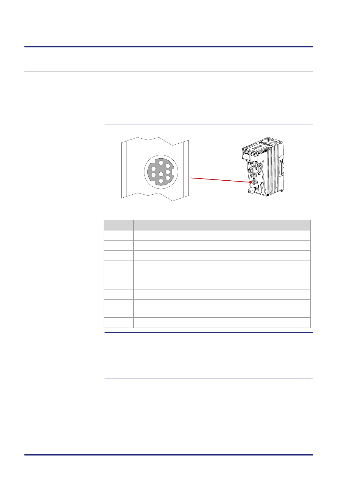
4 Mechanical and electrical installation
X11
S
E
R
1
2
3
4
5
8
7
6
Devices to connect with
Pin assignment of
Restrictions
Serial interface port X11
Port X11 lets you connect the following devices:
this port
port X11
A PC
An HMI by Jetter AG
Any device
Pin Signal Description
1
2
3
4
5
RDA RS-422; receive data inverted
GND Reference potential
RDB RS-422; receive data not inverted
RxD RS-232; receive data
SDB RS-422; transmit data not inverted
RS-485; transmit/receive data not inverted
6
7
8
DC 24 V HMI supply voltage
SDA RS-422; transmit data inverted
RS-485; transmit/receive data inverted
TxD RS-232; transmit data
Irrespective of the fact that various hardware drivers have been implemented,
only one hardware interface is available.
This means:
While, for example, communication via RS-422 is taking place, simultaneous
and independent communication via RS-232 is not possible.
44 Jetter AG
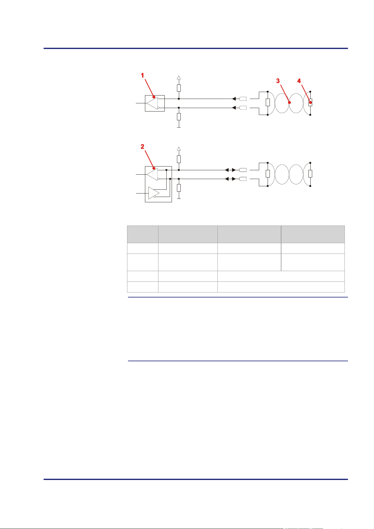
JC-120MC Mechanical and electrical installation
X11.3 [RDB]
X11.5 [SDB]
X11.1 [RDA]
X11.7 [SDA]
33 kΩ
33 kΩ
+3V3
+3V3
33 kΩ
33 kΩ
R
T
R
T
R
T
R
T
Receives and transmits
Block diagram
Terminating resistor
Number Part Function in the case
of RS-422
1
2
Receiver Receives data Unused
Receiver/transmitter Transmits data
Function in the case
of RS-485
data
3
4
Connect a terminating resistor to both serial lines in the following cases:
Long lines
High baud rates
Serial line Twisted line of the serial interface
Terminating resistor
R
T
Select a terminating resistor which corresponds to the impedance of the line
used.
Jetter AG 45

4 Mechanical and electrical installation
D,
D,
D,
D,
Technical specifications
Cables for port X11
Parameter Description
Type of terminal MiniDIN, shielded
Number of pins 8
Electrical isolation None
Number of interfaces 1 serial interface
Interface standards RS-232/RS-422/RS-485-2
Baud rates 2,400 ... 115,200 baud
Bits per character 5, 6, 7, 8
Number of stop bits 1, 2
Parity Even, odd, none, 1, 0
For connecting devices to port X11 you can order the following cables:
Item no. Item Description
60867209 KAY_0576-0050 JetControl to modem with 9-pin
Sub-D, length 0.5 m
60868359 Cable assy # 196 2.5M JetControl to PC with 9-pin Sub-D,
length 2.5 m
60860013 Cable assy # 196 5M JetControl to PC with 9-pin Sub-D,
length 5 m
60868956 Cable assy # 196 8M JetControl to PC with 9-pin Sub-D,
length 8 m
60860011 Cable assy # 192 2.5M JetControl to HMI with 15-pin Sub-
length 2.5 m
60860012 Cable assy # 193 5M JetControl to HMI with 15-pin Sub-
length 5 m
60872142 Cable assy # 192 10M JetControl to HMI with 15-pin Sub-
length 10 m
60872884 Cable assy # 192 15M JetControl to HMI with 15-pin Sub-
length 15 m
60864359 KAY_0386-0250 JetControl to LCD 60 with 15-pin
Sub-D, length 2.5 m
60864360 KAY_0386-0500 JetControl to LCD 60 with 15-pin
Sub-D, length 5 m
60864897 KAY_0533-0025 JetControl to LCD 52/54 with 15-pin
Sub-D, length 0.25 m
60864257 Cable assy # 197 5M JetControl to JetView 200/300 with
9-pin Sub-D, length 5 m
60871930 Cable assy # 197 12M JetControl to JetView 200/300 with
9-pin Sub-D, length 12 m
46 Jetter AG
JC-120MC Mechanical and electrical installation
X14
X15
E
T
H
E
R
N
E
T
Devices to connect with
Pin assignment
Technical specifications
Cables for ports X14 and
Ethernet ports - Female connectors X14, X15
Ports X14 and X15 let you connect the following devices:
these ports
A PC
An HMI by Jetter AG
A JX3-BN-ETH, a JX3-COM-xxxx, or a JetMove-200-ETH
Any device
Ports X14 and X15 are internally connected via Ethernet switch.
X15
Number Description
1
2
Connector X14 - Ethernet port
Connector X15 - Ethernet port
Parameter Description
Type of terminal RJ45 Ethernet port
Number of ports Two; one port per connector
Bit rate 10 MBit/s, 100 MBit/s (Cat 5e)
Auto-crossover Ye s
For connecting devices to ports X14 and X15 you can order the following
cables:
Item no. Item
60537500 Patch cable 1:1, 1 m gray Hirose, Cat 5e, shielded
60854512 Patch cable 1:1, 2 m gray Hirose, Cat 5e, shielded
60854514 Patch cable 1:1, 5 m gray Hirose, Cat 5e, shielded
60854515 Patch cable 1:1, 10 m gray Hirose, Cat 5e, shielded
Jetter AG 47

4 Mechanical and electrical installation
Introduction
Breakout cable
Supported modules
Contents
4.2 CAN bus interface - Female connector X19
This chapter describes the JX2 system bus interface and a CANopen®
interface (CANopen® STX API) on the JC-120MC.
At connector X19 two CAN buses are brought out.
To use both CAN buses, connect a Y-cable to connector X19.
One end of the Y-cable (CAN 1) lets you use either the JX2 system bus
protocol, or the CANopen® protocol. The protocol can be selected in
R 200002077. The other end of the cable (CAN 2) lets you use the CANopen®
protocol. To implement the functions of the CANopen® protocol, the
CANopen® STX API is used.
The CAN bus 1 (JX2 system bus) lets you connect the following devices:
JX2-I/O modules
JX2 slave modules
Servo amplifiers JetMove 1xx, JetMove 2xx, and JetMove 6xx
IP67 modules LioN-S and LJX7-CSL
Third-party CANopen® modules, e.g. valve terminals
CAN bus 1 or 2 (CANopen® STX API) lets you connect the following devices:
CANopen® modules
Topic Page
Female connector X19 - Pin assignment ...................................................... 49
Specification of the Y cable ........................................................................... 51
JX2 system bus cable specification .............................................................. 53
Line length and baud rate of the JX2 system bus ........................................ 55
48 Jetter AG

JC-120MC Mechanical and electrical installation
Pin assignment of
Technical specifications
Y-cable for connector
Female connector X19 - Pin assignment
female connector X19
X19
1
6
T
2
U
7
O
3
S
8
U
4
B
9
5
Pin Signal Description
X19
1
2
3
4
5
6
7
8
9
CMODE0 Commissioning
CAN-L Data signal for CAN bus 1
GND Reference potential
CMODE1 Commissioning
Unused
CAN-L_2 Data signal for CAN bus 2
CAN-H Data signal for CAN bus 1
CAN-H_2 Data signal for CAN bus 2
Unused
Parameter Description
Type of terminal Sub-D connector
Number of pins 9
Electrical isolation None
To order the Y-cable, specify the item number listed below:
Item no. Item
60880710 KAY_Breakout_Cable-second_CAN
Jetter AG 49

4 Mechanical and electrical installation
Bus cable
Related topics
For connecting modules to the CAN bus you can order the following cables
separately:
Item no. Item
10309001 Cable assy # 530 0.2 m
10309002 Cable assy # 530 0.5 m
10309003 Cable assy # 530 1.0 m
10309004 Cable assy # 530 1.5 m
10309006 Cable assy # 530 2.0 m
10309016 Cable assy # 530 2.5 m
10309015 Cable assy # 530 3.0 m
10309007 Cable assy # 530 4.0 m
10309008 Cable assy # 530 5.0 m
Y-cable - Specification (see page 51)
JX2 system bus cable - Specification (see page 53)
Line length (in mm) and baud rate (see page 55)
50 Jetter AG

JC-120MC Mechanical and electrical installation
1 1
1
2 2
2
3 3
3
4 4
4
5 5
5
6 6
6
7 7
7
8 8
8
9 9
9
Parts and connection
Specification of the Y cable
diagram
Jetter AG 51
Number Element Description
1
2
3
Male sub-D connector, 9-pin For connection to BUS OUT
Female sub-D connector,
For connection to BUS IN (CAN 1)
9-pin
Female sub-D connector,
For connection to BUS IN (CAN 2)
9-pin

4 Mechanical and electrical installation
Male sub-D connector
Sub-D connector (CAN 1)
Sub-D connector (CAN 2)
Number Element Description
4
Not connected Do not connect these pins
Pinout of the 9-pin male Sub-D connector on the Y-cable:
Pin Signal name Description
1
2
3
4
6
7
8
CMODE0 Commissioning
CAN-L Data signal CAN 1
GND Reference potential
CMODE1 Commissioning
CAN-L_2 Data signal CAN 2
CAN-H Data signal CAN 1
CAN-H_2 Data signal CAN 2
Pinout of the 9-pin female Sub-D connector (CAN 1) on the Y-cable:
Pin Signal name Description
1
2
3
4
7
CMODE0 Commissioning
CAN-L Data signal CAN 1
GND Reference potential
CMODE1 Commissioning
CAN-H Data signal CAN 1
Pinout of the 9-pin female Sub-D connector (CAN 2) on the Y-cable:
Pin Signal name Description
1
2
3
4
7
CMODE0 Commissioning
CAN-L_2 Data signal CAN 2
GND Reference potential
CMODE1 Commissioning
CAN-H_2 Data signal CAN 2
52 Jetter AG

JC-120MC Mechanical and electrical installation
1 1
2 2
3 3
4 4
5 5
6 6
7 7
8 8
9 9
JX2 system bus cable
Connection diagram
JX2 system bus cable specification
specification
Core cross-sectional area 1,000 kBaud: 0.25 … 0.34 mm2
Cable capacitance 60 pF/m max.
Parameter Description
500 kBaud: 0.34 … 0.50 mm2
250 kBaud: 0.34 … 0.60 mm
125 kBaud: 0.50 … 0.60 mm
2
2
Resistivity
1,000 kBaud: 70 Ω/km max.
500 kBaud: 60 Ω/km max.
250 kBaud: 60 Ω/km max.
125 kBaud: 60 Ω/km max.
Number of cores 5
Shielding Complete shielding, no paired shielding
Twisting Core pairs CAN-L and CAN-H are twisted
Number Part Description
1
2
Male Sub-D connector, 9-pin For connection to BUS-OUT
Female Sub-D connector,
For connection to BUS-IN
9-pin
3
Not connected Do not connect these pins
Jetter AG 53

4 Mechanical and electrical installation
Male Sub-D connector
Female Sub-D connector
Pinout of the 9-pin male Sub connector at the JX2 system bus cable:
Pin Signal name Description
1
2
3
4
5
7
CMODE0 Commissioning
CAN-L Data signal
GND Reference potential
CMODE1 Commissioning
TERM Short-circuited with pin 3
CAN-H Data signal
Pinout of the 9-pin female Sub-D connector to the JX2 system bus cable:
Pin Signal name Description
1
2
3
4
7
CMODE0 Commissioning
CAN-L Data signal
GND Reference potential
CMODE1 Commissioning
CAN-H Data signal
54 Jetter AG

JC-120MC Mechanical and electrical installation
Cable lengths
Rules for calculating the
Baud rate
Line length and baud rate of the JX2 system bus
The maximum cable length depends on the baud rate used and the number of
expansion modules connected to the bus.
Baud rate Cable length Stub length Total stub length
1,000 kBaud 25 m max. 0.3 m max. 3 m
500 kBaud 100 m max. 1.0 m max. 39 m
250 kBaud 200 m max. 3.0 m max. 78 m
125 kBaud 200 m max. - -
When engineering the line length, follow the rules listed below:
stub length
Each non-intelligent JX2-I/O module connected to the system bus reduces
the maximum line length by 1.0 m
Each connected intelligent JX2-I/O slave module reduces the maximum
line length by 1.0 m
Each JetMove reduces the maximum line length by 1.0 m
Each connected IP67-I/O module reduces the maximum line length by
1.0 m
The baud rate setting depends on the number of modules connected to the
JX2 system bus:
JX2-I/O modules
JX2 slave modules
JetMove
JX-SIO
CANopen®
modules
1,000
kBaud
500
kBaud
250
kBaud
125
kBaud
x
x x x
x x x x
x x x x x
x
Jetter AG 55

4 Mechanical and electrical installation
LEDs of the JC-120MC
Contents
4.3 LEDs indicating various states
The JC-120MC features the following LEDs:
5 LEDs for indicating conditions and errors of the controller
4 LEDs for indicating user-defined events
4 LEDs for indicating the conditions of the Ethernet ports
Topic Page
LEDs of the controller ................................................................................... 57
LEDs of the controller during boot process................................................... 59
LED indications on the controller after an IP address conflict has been
detected ........................................................................................................ 61
Status LEDs - Ethernet interface .................................................................. 62
56 Jetter AG
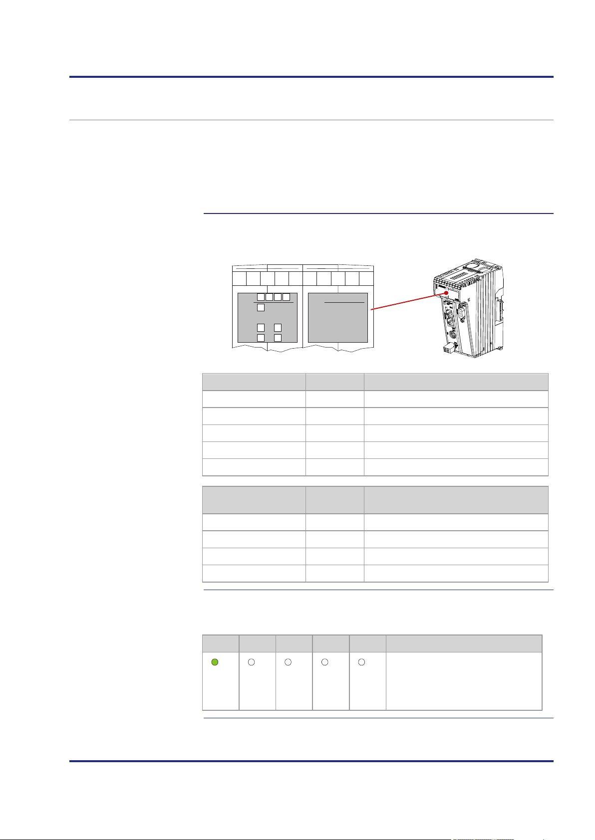
JC-120MC Mechanical and electrical installation
R
SD
U1
U3 U4
U2
E D1 D2
J
C
-
3
x
x
Jetter
ON
OFF OFF OFF OFF
No access to SD card
LEDs of the controller
OS- and
Normal operating
LEDs of the controller
The controller JC-120MC indicates conditions and errors via its LEDs. There
are three groups of LEDs:
The status LEDs of the OS and application-specific LEDs are located in the
application-specific
LEDs
diagnostic and status area below the labeling field.
Status messages of the operating system
Application-specific LEDs
Status of the Ethernet port
condition
OS LED Color Description
R
E
D1
D2
SD
Application-specific
Green OS is running
Red Generic error
Red Special conditions
Red Boot loader is running
Amber Access to SD card
Color Description
LED
U1
U2
U3
U4
Amber Programmable depending on the application
Amber Programmable depending on the application
Amber Programmable depending on the application
Amber Programmable depending on the application
In normal operating condition, the OS LEDs of the controller JC-120MC
indicate the following:
R E D1 D2 SD State
Jetter AG 57
Normal operating condition
Application program is running
No error

4 Mechanical and electrical installation
OFF
1Hz
4Hz
ON
OFF
1Hz
4Hz
ON
OFF
1Hz
4Hz
ON
OFF
1Hz
4Hz
ON
States of the OS LEDs
The table below shows the possible states of the OS-LEDs R, E, D1 und D2:
LED State Description
R
E
D1
D2
No power supply or failure
Either the controller does not boot up, or it does not
execute the application program.
Reset or fatal error
Application program is being executed
No error
No valid OS
Reset, fatal error, or checking the network consistency
Error; refer to error register
Normal operating condition
Automatic IP configuration, or AutoCopy function is
completed, or first part of startup delay is carried out.
Reset or second part of startup delay is carried out, or
fatal error has occurred.
File autocopy.ini on SD card is being executed.
Boot loader is not running
Boot loader: Automatic IP configuration
Reset or fatal error
Boot loader is being executed
58 Jetter AG

JC-120MC Mechanical and electrical installation
4Hz 4Hz 4Hz 4Hz
1Hz
OFF OFF
ON
1Hz
OFF OFF OFF
1Hz
ON
OFF OFF
register R 202971 a time value has been entered, the
1Hz
ON
1Hz
OFF
Normal boot process
LEDs of the controller during boot process
If the following requirements are met, the controller goes through its normal
boot process:
Mode selector S11 is in RUN position.
There is a valid OS.
There is a valid application program.
The LED SD is not shown here, as it is OFF during the normal boot process.
During boot process of the controller, the other OS status LEDs then indicate
the following:
Step Description
1
R E D1 D2 State
2
Reset
R E D1 D2 State
3
Boot loader is running and is
checking the OS
R E D1 D2 State
The OS reads out the DIP switch
settings on the backplane module.
Then, it checks if an Ethernet switch
exists.
4
R E D1 D2 State
5a
Only if in start delay
The OS initializes real-time clock,
Ethernet interface and file system.
controller executes steps 5a and 5b.
R E D1 D2 State
The first half of the start delay is in
progress
Jetter AG 59
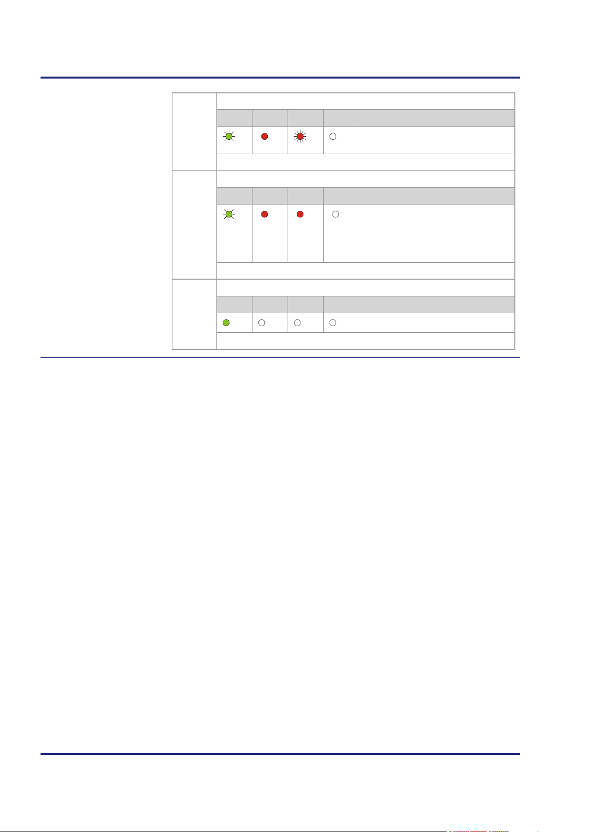
4 Mechanical and electrical installation
1Hz
ON
4Hz
OFF
1Hz
ON ON
OFF
ON
OFF OFF OFF
5b
R E D1 D2 State
6
The second half of the start delay is
in progress
R E D1 D2 State
The OS initializes the modules on the
JX3 and JX2 system bus, as well as
software features (Web,
Modbus/TCP, etc.); then it loads the
application program.
7
R E D1 D2 State
Normal operating condition
60 Jetter AG

JC-120MC Mechanical and electrical installation
ON
1Hz 1Hz
IP conflict detected
LED indications on the controller after an IP address conflict has been detected
During booting or after the IP address has been modified through
NetConsistency, the controller checks its own IP address. If the controller
detects that its IP address is already used on the network, it takes the
following actions:
The controller sets bit 24 in R 200009.
The controller sets bit 7 in R 200008. This is the collective error bit of
R 200009.
Then, the LEDs on the controller indicate the following:
E D1 D2 State
The controller has detected an IP address conflict.
To exit this state, the following two steps must be taken:
Step Action
1
Resolve the IP address conflict.
2
Restart the controller.
Jetter AG 61

4 Mechanical and electrical installation
X14
X15
E
T
H
E
R
N
E
T
Status LEDs - Ethernet
Status LEDs - Ethernet interface
The status LEDs of the Ethernet interface are located in the immediate vicinity
interface
of the RJ45 ports.
LED Color Description
X14-1 Green LINK: Network connection has been established
X14-2 Amber ACT: Data transmission
X15-3 Green LINK: Network connection has been established
X15-4 Amber ACT: Data transmission
62 Jetter AG

JC-120MC Mechanical and electrical installation
Control element of
SD card
Contents
4.4 Controls and SD memory card
The JC-120MC is equipped with the following controls:
JC-120MC
Mode selector S11 with the following positions: RUN, STOP, and LOAD
The JC-120MC is equipped with a slot for SD memory cards.
Topic Page
Function description of mode selector S11................................................... 64
SD card slot X61 ........................................................................................... 66
Jetter AG 63

4 Mechanical and electrical installation
X14
S11
RUN
STOP
LOAD
Mode selector S11
Functions of the mode
Function description of mode selector S11
Position Behavior after power-up
selector
RUN
STOP
LOAD The controller executes the file autocopy.ini which is located
The controller launches the application program.
The controller does not launch the application program.
on the SD card.
The JC-120MC checks the position of selector S11 in the following way:
Step Description
1
Power supply of the controller is at terminal X10.
2
The boot loader of the controller checks the position of selector S11.
If ... ... then ...
... mode selector S11 = RUN or
STOP, ...
... selector S11 = LOAD position,
and an SD card has been inserted.
... selector S11 = LOAD position,
and an SD card has not been
inserted.
3 The controller loads the fileautocopy.ini.
If ... ... then ...
... the OS is launched;
--> proceed with step 4.
... the OS is launched;
--> proceed with step 3.
... the boot loader waits until an OS
update is carried out
4
If ... ... then ...
64 Jetter AG
... the file could be loaded, ... ... the instructions contained in it are
executed.
... the file could not be loaded, ... ... proceed with step 4.
The controller checks the position of selector S11.
... mode selector S11 = RUN, ...
... mode selector S11 = STOP, ...
... the application program is
launched.
... the application program does not
start.

JC-120MC Mechanical and electrical installation
Step Description
5 If ... ... then ...
... the position of mode selector
S11 is changed once the controller
has been turned on, ...
... this has no effect on the
functioning of the controller.
Jetter AG 65
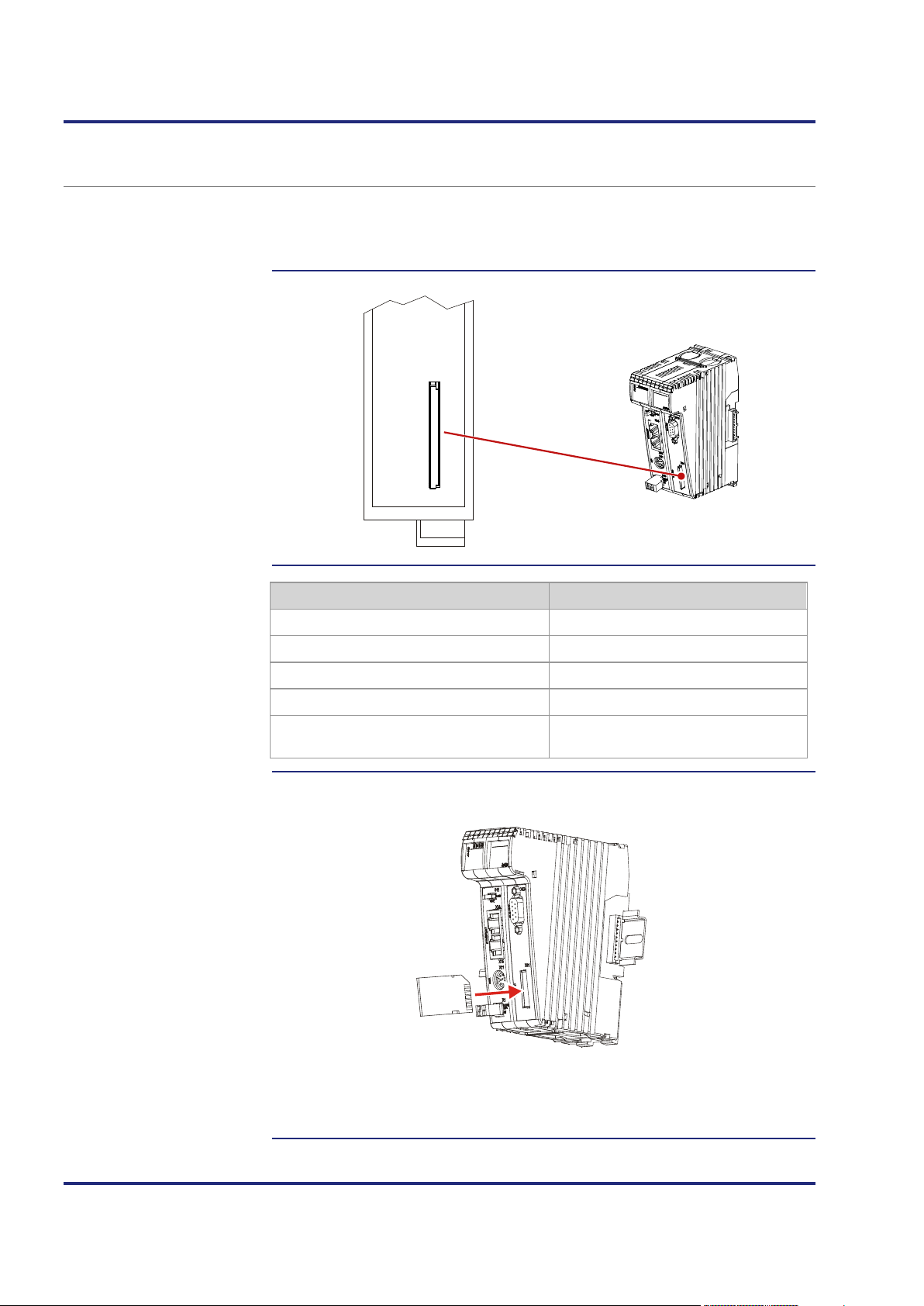
4 Mechanical and electrical installation
S
D
C
A
R
D
X61
Introduction
SD card slot - Position
Technical specifications
Inserting the SD card
SD card slot X61
The SD card slot is for accommodating standard SD memory cards. The
controller accesses data stored on the SD card which is used as file system
extension.
Parameter Description
Plug-in card type Standard SD card
Mechanical operation push/push
Maximum memory size 32 MB ... 32 GB
Card format FAT
Protection against inserting the SD card in
Yes
the wrong direction
Insert the SD card into the SD slot as illustrated below.
The way of inserting the SD card correctly is the same as in common digital
cameras. If the SD card has been inserted correctly, the status LED SD lights
66 Jetter AG
up for 300 ms.

JC-120MC Mechanical and electrical installation
Removing the SD card
Make sure the SD card is not accessed, while you are removing it. First, close
all files which are stored to the SD card.
Remove the SD card the same way as you do it with digital cameras.
After removing the SD card, the status LED SD lights up twice for 100 ms
each time.
Jetter AG 67

4 Mechanical and electrical installation
Introduction
Contents
4.5 Installing, replacing and removing the module
This chapter covers mounting, replacing and removing of controllers belonging
to the JetControl 120 series.
Topic Page
Installing the JC-120MC on a DIN rail .......................................................... 69
Replacing the controller JC-120MC .............................................................. 70
Removing the JC-120MC from the DIN rail .................................................. 72
68 Jetter AG
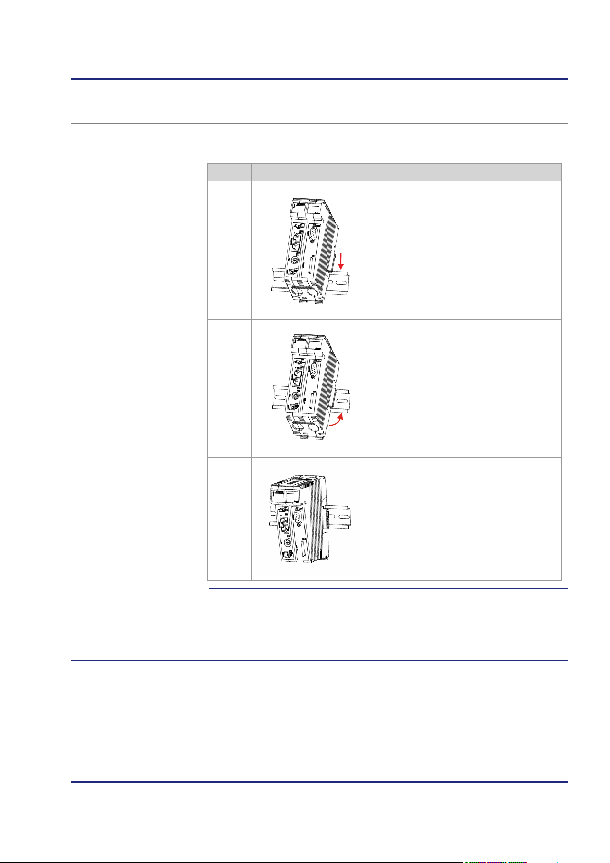
JC-120MC Mechanical and electrical installation
Installing
Related topics
Installing the JC-120MC on a DIN rail
To install the controller on a rail to DIN EN 50022 proceed as follows:
Step Action
1
2
3
Place the controller on the upper edge of
the DIN rail.
Move the controller in the direction of the
arrows until it snaps into place.
Installation of the controller on the
DIN rail is now completed.
Replacing the controller JC-120MC (see page 70)
Removing the controller JC-120MC from the DIN rail (see page 72)
Jetter AG 69

4 Mechanical and electrical installation
Introduction
Removing the controller
Replacing the controller JC-120MC
At replacing a controller of the JetControl 120 series, the following
configuration information is retained on the backplane module:
IP address
Subnet mask
Gateway
DNS server
To remove the JC-120MC from the backplane module, proceed as follows:
Step Action
1
Remove power from the JX3 station.
2
Press the upper and lower latches
located on the right half of the
JC-120MC.
Keep the latches pressed.
3
Pull off the controller from the
backplane module.
70 Jetter AG
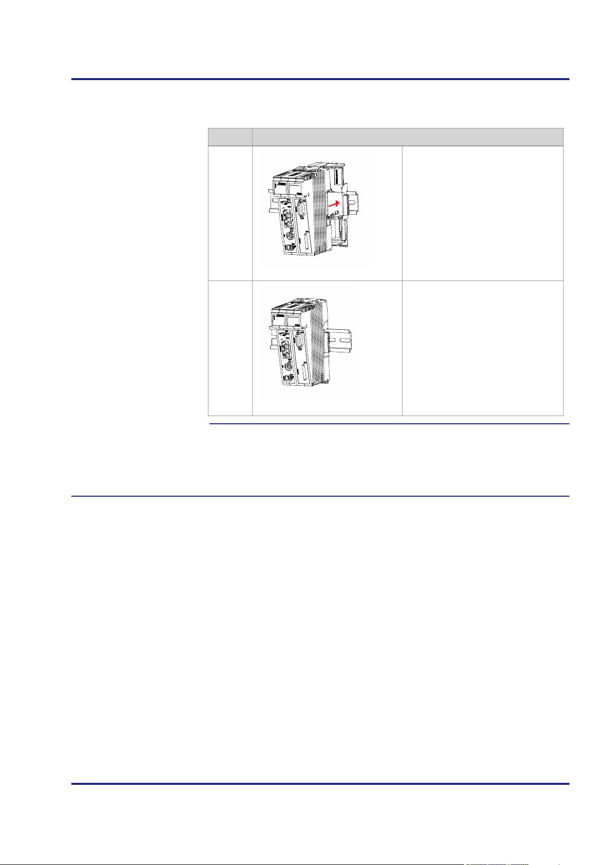
JC-120MC Mechanical and electrical installation
Installing the controller
Related topics
To install the JC-120MC on the backplane module, proceed as follows:
Step Action
1
Slide the controller onto the
backplane module until the latches
snap into place.
2
Installation of the controller to the
backplane module is now completed.
Installing the JC-120MC on a DIN rail (see page 69)
Removing the JC-120MC from the DIN rail (see page 72)
Jetter AG 71

4 Mechanical and electrical installation
Removing
Related topics
Removing the JC-120MC from the DIN rail
To remove the JC-120MC from a rail to DIN EN 50022 proceed as follows:
Step Action
1
Remove power from the JX3 station.
2
Slide the controller to the left. By doing so, the backplane module is
disconnected from the JX3 peripheral modules.
3
Pull down the right DIN rail latch
using a flat-bladed screwdriver.
4
5
Swing the controller forward.
Remove the controller from the
DIN rail.
Installing the JC-120MC on a DIN rail (see page 69)
Replacing the controller (see page 70)
72 Jetter AG

JC-120MC Mechanical and electrical installation
Introduction
Required skills of the
Contents
4.6 IP configuration
This chapter describes the IP configuration for the controller JC-120MC. The
following parameters can be set:
IP address of the controller
Subnet mask
IP address of default gateway
IP address of DNS server
Controller name
IP port number for the JetSym debugger
Basic port number for communication via JetIP
Name for AutoCopy command file
To carry out IP configuration of the JC-120MC knowledge of IP networks is
network configurator
required, such as
IP addressing (IP address, port number, subnet masks etc.)
FTP (connection setup, data transmission, etc.)
Topic Page
Factory settings ............................................................................................ 74
The configuration memory ............................................................................ 75
The configuration file .................................................................................... 76
Configuration registers ................................................................................. 80
Changing the IP address of the controller .................................................... 81
Setting the default IP address 192.168.10.15 .............................................. 82
Setting the IP address via configuration file ................................................. 83
Setting the IP address via configuration file and DIP switch ........................ 84
Setting the IP address via registers to be non-volatile ................................. 86
Setting the IP address during runtime .......................................................... 88
IP address in the GNN operating mode ........................................................ 89
Using names for IP addresses ..................................................................... 91
Jetter AG 73

4 Mechanical and electrical installation
Introduction
Factory settings
Factory settings
Before the JC-120MC is shipped, various parameters are set to a certain
value.
The parameters can be changed by the user.
Parameter Value
IP address of the controller 192.168.1.1
Subnet mask 255.255.255.0
IP address of default gateway 0.0.0.0
IP address of DNS server 0.0.0.0
Controller name JetControl120MC
IP port number for debugger 52000
IP port number for JetIP 50000
Name for AutoCopy command file /SD/autocopy.ini
DIP switch DIP switch slider 1 = ON
All other DIP switch sliders = OFF
User's password admin
admin
User's password system
system
74 Jetter AG

JC-120MC Mechanical and electrical installation
Introduction
Enabling conditions
Default values
Storage
Related topics
The configuration memory
The controller reads the parameters for initializing the IP interface out of the
configuration memory during the boot process. The user can access the data
stored in the configuration memory in the following ways:
A file located in the system directory of the file system lets you read out
and modifiy data.
Various registers or one registers let you read out data.
The controller reads out data located in the configuration memory only during
the boot process. If you make changes to the configuration memory, reboot
the controller for these changes to take effect. Only this way these changes
take effect.
Before the controller further processes data from the configuration memory, it
checks them for plausibility. If entries are invalid or absent, the controller uses
the following default values:
Parameter Default value
location/controller
replacement
IP address of the controller 192.168.10.15
Subnet mask 255.255.255.0
IP address of default gateway 0.0.0.0
IP address of DNS server 0.0.0.0
Controller name JetControl120MC
Suffix type of the name 0
IP port number for debugger 52000
IP port number for JetIP 50000
Name for AutoCopy command file /SD/autocopy.ini
The configuration memory is located on the backplane module.
Owing to this approach, configuration data will be preserved when the function
module is replaced.
The configuration file (see page 76)
Configuration registers (see page 80)
Jetter AG 75

4 Mechanical and electrical installation
Introduction
Properties
File structure
Configuration file -
The configuration file
The configuration file config.ini is used to access the configuration memory of
the JC-120MC.
You can access this file through the file system of the JC-120MC.
The configuration file is a text file the entries of which are grouped into several
sections. The controller replaces missing IP configuration parameters by their
default values.
This is an example of a configuration file config.ini:
Example
;<Productname> System Configuration
;Copyright (c) 2008 by Jetter AG, Ludwigsburg, Germany
[IP]
Address = 192.168. 50. 1
SubnetMask = 255.255.255. 0
DefGateway = 192.168. 50. 11
DNSServer = 192.168. 1. 44
[HOSTNAME]
SuffixType = 0
Name = JetControl120MC
[PORTS]
JetIPBase = 50000
JVMDebug = 52000
[FILES]
AutoCopyIni = /SD/autocopy.ini
For an FTP connection, the user must have administrator or system rights.
This file is located in the folder System.
You cannot delete the file, but only overwrite it.
Formatting the Flash disk drive or the SD card leaves the file unchanged.
76 Jetter AG

JC-120MC Mechanical and electrical installation
< 223.255.255.255
Broadcast address
< 223.255.255.255
The "Address" value
< 223.255.255.255
Section [IP]
In section [IP] the required IP addresses and the subnet mask are specified.
Address
In the given example 192.168.50.1
Description IP address of the JC-120MC
The DIP switch on the backplane module can overwrite
the least significant byte.
Allowed values
> 1.0.0.0
Illegal values
In the event of an illegal
value
SubnetMask
In the given example 255.255.255.0
Description Sets the subnet mask
Allowed values
Illegal values
In the event of an illegal
value
DefGateWay
In the given example 192.168.50.11
Description IP address of the gateway to other subnets;
Allowed values
Illegal values
Network address
JC-120MC resets all four values to their defaults.
>= 128.0.0.0
1 and 0 mixed
JC-120MC resets all four values to their defaults.
The JC-120MC must be able to reach the subnet
(Address/SubnetMask), otherwise it will set this
parameter to 0.0.0.0.
>= 0.0.0.0 and
Network address
Broadcast address
A value (Address/SubnetMask) which cannot be
reached by the JC-120MC.
In the event of an illegal
value
DNSServer
In the given example 192.168.1.44
Description IP address of the server for the Domain Name System
Allowed values
In the event of an illegal
value
JC-120MC sets the value to 0.0.0.0
>= 0.0.0.0 and
JC-120MC sets the value to 0.0.0.0
Jetter AG 77

4 Mechanical and electrical installation
notation
Next characters: 'A' ... 'Z', 'a' ... 'z', '0' ... '9', '-'
Section [HOSTNAME]
Section [PORTS]
In section [HOSTNAME] the name of the JC-120MC is specified. If desired,
the JC-120MC automatically generates an individual name. The JC-120MC
presently does not use the host name.
SuffixType
In the given example 0
Description The type of the automatically generated suffix is
attached to the controller name
Allowed values
0: No suffix
1: Low-order byte of the IP address in decimal
notation
2: Low-order byte of the IP address in hexadecimal
In the event of an illegal
value
Name
In the given example JetControl120MC
Description Specifies the name of the JC-120MC
Allowed values
In the event of an illegal
value
0
First character: 'A' ... 'Z', 'a' ... 'z'
JetControl120MC
In section [PORTS] the IP port numbers of data and debug servers within the
JC-120MC are specified. The IP port numbers must be consistent with, for
example, the port numbers set in JetSym.
JetIPBase
In the given example 50000
Description IP port for OS update and communication between
controllers
Allowed values
In the event of an illegal
value
JVMDebug
1024 ... 65535
50000
In the given example 52000
Description IP port for debugger/setup in JetSym
Allowed values
In the event of an illegal
value
78 Jetter AG
1024 ... 65535
52000

JC-120MC Mechanical and electrical installation
Section [FILES]
Changing the
Related topics
IP configuration
In the [FILES] section, the name of the command file for the AutoCopy
function has been entered.
AutoCopyIni
In the given example /SD/autocopy.ini
Function Command file for the AutoCopy function
Allowed values Valid name of path and file
In the event of an illegal
value
Step Action
1 Create on your PC a configuration file named config.ini using a text editor
and make the corresponding entries.
2
Open an FTP connection between the PC and the JC-120MC.
3
Log in as user with administrator or system rights.
Default login information:
User: admin, Password: admin
User: system; Password: system
4
Browse to directory /System of the JC-120MC.
/SD/autocopy.ini
5 Copy the configuration file named config.ini, which has been created by
you, to the JC-120MC.
6
Clear the FTP connection.
7
Reboot the JC-120MC.
Result:
The new configuration is active.
As an alternative, you can change the IP configuration via the configuration
registers.
The configuration memory (see page 75)
Configuration registers (see page 80)
Jetter AG 79

4 Mechanical and electrical installation
Address
SubnetMask
DefGateWay
DNSServer
SuffixType
Name
JetIPBase
JVMDebug
AutoCopyIni
Introduction
Register numbers
Configuration registers
Related topics
Configuration registers
Configuration registers let you read the parameters of the IP configuration. A
range of registers holds the data contained in the configuration memory.
Another range contains the parameters used for initializing the IP interface.
The basic register numbers of both ranges are dependent on the device. The
register number is calculated by adding the number of the module register
(MR) to the number of the basic register.
Device Data range Basic register
number
Register numbers
JC-120MC
Configuration
memory
Parameters
101100 101100 ... 101165
101200 101200 ... 101265
used
The following table lists the registers of both ranges, as well as their
connection to the entries in the configuration file /System/config.ini:
Register Section in
config.ini
MR 0
MR 1
MR 2
MR 3
MR 32
MR 33
IP
HOSTNAME
through
51
Name in
config.ini
Description
IP address of the controller
Sets the subnet mask
IP address of the gateway to other
subnets
IP address of the server for the Domain
Name System
The type of the automatically generated
suffix is attached to the controller name
Specifies the controller name
MR 64
MR 65
MR 80
The configuration memory (see page 75)
The configuration file (see page 76)
80 Jetter AG
PORTS
FILES
IP port number for OS update and
communication between controllers
IP port number for debugger/setup in
JetSym
Name for AutoCopy command file

JC-120MC Mechanical and electrical installation
Introduction
Replacing the controller
Configuration options
Changing the IP address
Related topics
Changing the IP address of the controller
To be able to communicate with the controller JC-120MC via Ethernet, you
must set an unambiguous IP address on the controller.
The IP address is stored to the backplane module. When you install another
controller of the JetControl 120 series to the backplane module, the following
configuration data are preserved:
IP address of the controller
Subnet mask
IP address of default gateway
IP address of DNS server
Controller name
Suffix type of the name
IP port number for debugger
IP port number for JetIP
Name for AutoCopy command file
You can configure the IP address in the following ways:
Default IP address
Configuration via file config.ini
Configuration via file config.ini and DIP switch
Configuration via the configuration registers
Configuration during runtime via special registers
Step Action
Jetter AG 81
1
Remove power from the controller JC-120MC.
2
Remove the controller enclosure from the backplane module.
3
Make the corresponding DIP switch settings.
4
Reinstall the enclosure on the backplane module.
Following restart, the controller JC-120MC can be reached at the new
IP address.
Replacing the controller (see page 70)
Default IP address 192.168.10.15 (see page 82)
Setting the IP address via configuration file (see page 83)
Setting the IP address via configuration file and DIP switch (see
page 84)
Setting the IP address during runtime (see page 88)

4 Mechanical and electrical installation
ON
1 2 3 4 5
6
7 8
9
10 11
12
Default IP address
DIP switch settings
Setting the default IP address 192.168.10.15
The controller JC-120MC has got default IP address 192.168.10.15. You may
change the IP address of the JC-120MC to its default IP address at any time.
To set the module to its default IP address 192.168.10.15, move the
DIP switch sliders to the positions shown below:
82 Jetter AG
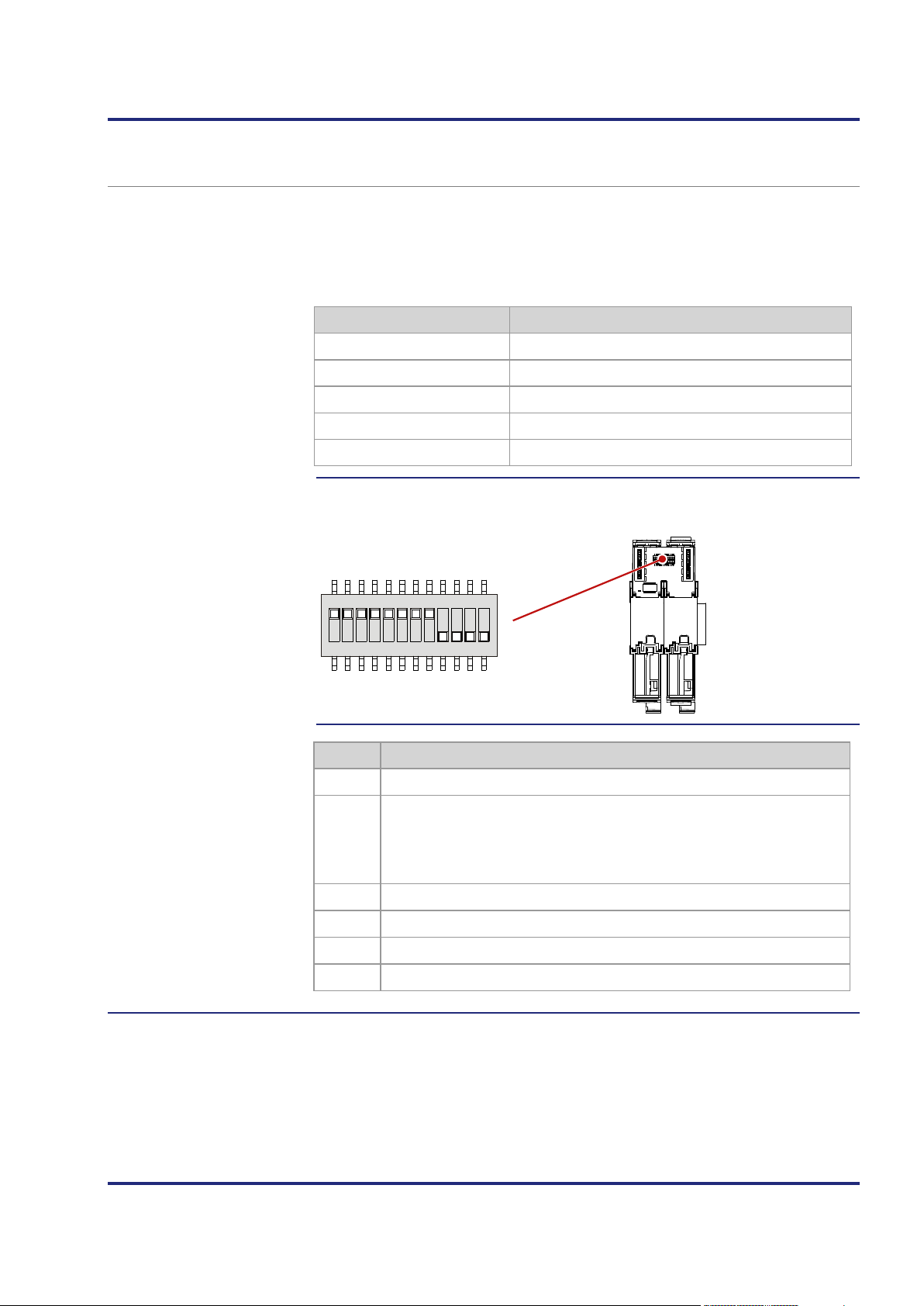
JC-120MC Mechanical and electrical installation
Address
aaa
bbb
ccc
ddd
ON
1 2 3 4 5 6 7 8 9 10 11 12
Setting the IP address
DIP switch settings
Transferring the
Setting the IP address via configuration file
You can set the IP address of the controller JC-120MC in the config.ini file.
[IP]
Address = aaa.bbb.ccc.ddd
...
Element Description
Enter the IP-address into this line.
First byte of IP address
Second byte of IP address
Third byte of IP address
Fourth byte of IP address
The following DIP switch settings cause the controller JC-120MC to read out
the IP address from the file config.ini:
configuration file
Step Action
1
Establish an FTP connection to the JC-120MC.
2
Log in as user with administrator or system rights.
Default login information:
User: admin; Password: admin
User: system; Password: system
3 Open the folder System.
4 Copy the file config.ini into the folder System.
5
Clear the FTP connection.
6
Reboot the JC-120MC.
Jetter AG 83

4 Mechanical and electrical installation
Address
aaa
bbb
ccc
1
ON
1 2 3 4 5 6 7 8 9 10 11 12
Introduction
Configuration file DIP switch settings
Setting the IP address via configuration file and DIP switch
You can set the IP address of the JC-120MC via the configuration file
config.ini and the DIP switch sliders. To this end, set the three upper bytes of
the IP address in theconfig.ini file, and the lower byte using the DIP switch
sliders.
Set the upper three bytes of the IP address of the JC-120MC in the
Setting the IP address
configuration file config.ini file.
[IP]
Address = aaa.bbb.ccc.1
...
Element Description
Line for entering the upper 3 bytes of the IP address
First byte of IP address
Second byte of IP address
Third byte of IP address
Dummy entry, must have got value one.
The following DIP switch settings cause the JC-120MC to read out the
IP address from the file config.ini and the DIP switches:
DIP switch IP address
1 2 3 4 5 6 7 8
OFF OFF OFF OFF OFF OFF OFF OFF Default IP address
ON
OFF OFF OFF OFF OFF OFF OFF aaa.bbb.ccc.1
OFF
ON ON
OFF
ON ON ON ON ON ON ON ON
ON
OFF OFF OFF OFF OFF OFF aaa.bbb.ccc.2
OFF OFF OFF OFF OFF OFF aaa.bbb.ccc.3
...
ON ON ON ON ON ON ON
aaa.bbb.ccc.254
from config.ini
84 Jetter AG

JC-120MC Mechanical and electrical installation
Transferring the
configuration file
Step Action
1
Establish an FTP connection to the JC-120MC.
2
Log in as user with administrator or system rights.
Default login information:
User: admin; Password: admin
User: system; Password: system
3 Open the folder System.
4 Copy the file config.ini into the folder System.
5
Clear the FTP connection.
6
Reboot the JC-120MC.
Jetter AG 85

4 Mechanical and electrical installation
Introduction
Registers - Overview
Setting the configuration
Setting the IP address via registers to be non-volatile
The IP interface is initialized by the settings in the configuration memory
during the boot process.
The following non-volatile settings can also be changed via register:
IP address of the controller
Subnet mask
IP address of default gateway
IP address of DNS server
Host name and suffix type
Port numbers for JetIP and the JetSym debugger
Name for AutoCopy command file
Overview over the configuration memory registers:
Registers Description
values to be non-volatile
101200
101201
101202
101203
101232
101233 through
101251
101264
101265
101280 through
101298
101299
IP address
Subnet mask
IP address of default gateway
IP address of DNS server
Host name suffix type
Host name
Port number for JetIP
Port number for STX debugger
Name for AutoCopy command file
Saving the settings (0x77566152)
To change the configuration values to become non-volatile, proceed as
follows:
Step Action
1
Enter the desired configuration into one or several registers within the
range from 101200 to 101298.
2
To have the controller take over the values, you must enter a password.
For this, write value 2002149714 (0x77566152) to register 101299.
3
Wait for the controller to write value 0 into MR 101299.
The save process is now completed.
4
Boot the controller.
Result: The settings are completed. Communication is possible again.
86 Jetter AG

JC-120MC Mechanical and electrical installation
Effect
Related topics
Important note:
The EEPROM data on the backplane module allow for 100,000 write cycles.
We urgently recommend the following workflow:
First read out the value, then compare it. Only if the value has changed, start
writing.
Write to register 101299 to have the controller take the following steps:
The controller creates a configuration file out of the values.
It saves the configuration file to the backplane module as
/System/config.ini.
If you have entered comments and formatting details into this file, the
comments and formatting details will get lost during this process.
The configuration memory (see page 75)
Setting the IP address during runtime (see page 88)
Setting the IP address via configuration file (see page 83)
Setting the IP address via configuration file and DIP switch (see
page 84)
Jetter AG 87

4 Mechanical and electrical installation
Introduction
Important note
Prerequisites
Register overview
Setting IP addresses and
Related topics
Setting the IP address during runtime
The IP interface is initialized by the settings in the configuration memory
during the boot process.
The following settings can also be changed via registers to be non-remanent:
IP address of the controller
Subnet mask
IP address of default gateway
The settings made during runtime do not change the parameters in the
configuration memory. At de-energizing the controller, your settings will be lost.
While settings are being made, no communication via IP interface is
allowed. Otherwise, this would lead to a loss of data.
The values entered must be valid. This can be ensured, e.g. by including a
validity check in the application program.
This is important because there is no check if you set the parameters
during runtime of the controller.
Register Description
subnet mask
104531
104532
104533
IP address of the JC-120MC
Subnet mask
IP address of default gateway
To set the IP address and the subnet mask, proceed as follows:
Step Action
1
Enter the value 0.0.0.0 into 104533.
2
Enter the value 0.0.0.0 into 104532.
3
Enter the desired IP address into register 104531.
4
Enter the desired subnet mask into register 104532.
5
Enter the desired IP address of the Default Gateway into 104533.
Result:
The settings are completed. Communication is possible again.
The configuration memory (see page 75)
88 Jetter AG

JC-120MC Mechanical and electrical installation
Address
aaa
bbb
ccc
ddd
Introduction
Configuration file DIP switch settings
IP address in the GNN operating mode
In GNN mode (Global Network Number mode), the JC-120MC functions as a
network node within a greater controller network. It derives its IP address at
booting from the configuration file config.ini. Next, the main controller, which
is the NetConsistency master, commands the network node to log in with the
GNN from the NetConsistency master. After accepting the network node, the
main controller compares the set IP configuration with the actual
IP configuration of the network node. If a difference results, the main controller
makes the corresponding changes in the set IP configuration in the network
node.
Set the IP address in the configuration file config.ini.
Setting the IP address
[IP]
Address = aaa.bbb.ccc.ddd
...
Element Description
Line for entering the IP address
First byte of IP address
Second byte of IP address
Third byte of IP address
Fourth byte of IP address
The following DIP switch settings cause the JC-120MC to read out the IP
address from the file config.ini and the GNN out of the lower eight positions
of the DIP switches:
Valid values for the GNN: 1 ... 199.
The DIP switches are binary-coded.
DIP switch GNN
1 2 3 4 5 6 7 8
OFF OFF OFF OFF OFF OFF OFF OFF Invalid
ON
OFF
OFF OFF OFF OFF OFF OFF OFF 1
ON
OFF OFF OFF OFF OFF OFF 2
Jetter AG 89

4 Mechanical and electrical installation
DIP switch GNN
ON ON
...
ON ON ON
...
ON ON ON ON ON ON ON ON
OFF OFF OFF OFF OFF OFF 3
OFF OFF OFF
ON ON
199
Invalid
Invalid
90 Jetter AG

JC-120MC Mechanical and electrical installation
... it enters the name and IP address
Introduction
Name resolution
Configuration file
Using names for IP addresses
Names can be specified as IP addresses for target systems, e.g. when
configuring the e-mail client. The JC-120MC resolves the names into
IP addresses. A configuration file or the Domain Name System is used to
assign names to their corresponding IP address.
Names are resolved to IP addresses in the following way:
Step Description
1
During the boot process the JC-120MC reads the IP address of the DNS
server out of the configuration memory.
2 During the boot process the JC-120MC reads the file /etc/hosts. The
JC-120MC creates a translation table with the names and IP addresses
found in this file.
3
After the boot process the JC-120MC detects a name instead of an
IP address.
4
Based on this translation table, the JC-120MC tries to resolve the name
into a related IP address.
If ... ... then ...
... the JC-120MC has resolved the
... proceed with step 6.
name, ...
... the JC-120MC has not resolved
... proceed with step 5.
the name, ...
5
The JC-120MC tries to resolve the name into a related IP address by
sending a request to the DNS server.
If ... ... then ...
... the JC-120MC has resolved the
name, ...
into the translation table;
--> proceed with step 6.
... the JC-120MC has not resolved
the name, ...
... the JC-120MC aborts the
function, e.g. the system function for
sending an e-mail, and issues an
error message.
6
The JC-120MC uses the IP address resolved for further communication.
This configuration file hosts holds the static assignment between names and
IP addresses. The JC-120MC reads this file once during boot-up.
File format: Text
Location: /etc
File name: hosts
Jetter AG 91

4 Mechanical and electrical installation
Domain Name System
Related topics
(DNS)
Example
# Example - hosts file for JC-3xx
192.168.33.209 jetter_mail
192.168.33.208 jetter_demo
192.168.1.1 JC340
192.168.1.2 JC350
If a name cannot be found in the file /etc/hosts, the JC-120MC tries to obtain
the corresponding IP address from a DNS server. During boot-up, the
JC-120MC reads the IP address of the DNS server out of the configuration
memory.
The configuration memory (see page 75)
92 Jetter AG

JC-120MC Mechanical and electrical installation
Introduction
JX3 station
Number of connectable
Contents
4.7 Engineering of JX3 station equipped with a JC-120MC
This chapter describes how to engineer a JX3 station equipped with a
JC-120MC.
A JX3 station consists of a JX3-BN-xxx bus node or a JC-120MC controller
and JX3 peripheral modules connected to it.
The possible number of JX3 modules depends on the following parameters:
JX3 modules
Maximum number of JX3 modules
Maximum data exchange rate
Maximum power consumption
Topic Page
Limitations to be taken into account when engineering a JX3 station .......... 94
Jetter AG 93

4 Mechanical and electrical installation
Introduction
JX3 system bus
JX3 systembus data
4.7.1 Limitations to be taken into account when engineering a JX3 station
This chapter covers the following limitations of a JX3 station:
Maximum number of JX3 modules
Maximum data interchange rate
Maximum power consumption
Take all three limitations into account when engineering a JX3 station and
match the JX3 peripheral modules considering all limiting factors. If you need
more JX3 peripheral modules for your plant, you can expand it by means of
JX3-BN-xxx.
The JX3 system bus configurator assists you in detecting limitations through
configurator
engineering a real JX3 station.
In this case, enter the amount of your JX3 modules into an Excel file. The
JX3 system bus configurator calculates the possibility of the above named
limitations.
There are two Excel sheets JX3 systembus data and JX3 systembus
power.
Here, the maximum number of JX3 modules and maximum data interchange
rate is determined.
The following fields marked red convey the following meaning:
Total number of modules
The maximum number of 16 JX3 modules per JX3 station has been
exceeded.
IN size of JX3 station
The aggregated input factor has been exceeded.
94 Jetter AG

JC-120MC Mechanical and electrical installation
JX3 systembus power
JX3 system bus
OUT size of JX3 station
The aggregated output factor has been exceeded.
Here, the maximum number of JX3 modules and maximum power
consumption is determined.
configurator - Download
The following fields marked red convey the following meaning:
Number of modules
The maximum number of 8 JX3 modules connected to JC-120MC,
JX3-BN-xxx, or JX3-PS1 has been exceeded.
Integrate the JX3-PS1 in your JX3 station.
JC-3xx/JX3-BN-ETH
The power consumption of the JX3 modules which are directly connected
to a JC-120MC or a JX3-BN-ETH is too high.
Insert a JX3-PS1 into your JX3 station.
JX3-BN-CAN
The power consumption of the JX3 modules which are directly connected
to a JX3-BN-CAN is too high.
Insert a JX3-PS1 into your JX3 station.
JX3-PS1
The power consumption of the JX3 modules which are directly connected
to a power supply module JX3-PS1 is too high.
Insert a JX3-PS1 into your JX3 station.
Jetter AG provide the JX3 system bus configurator on their homepage
http://www.jetter.de. You can find the JX3 system bus configurator for
download at Downloads – Expansion modules – JX3 modules -
JX3 system bus.
Jetter AG 95

4 Mechanical and electrical installation
Contents
Topic Page
Limitations of the maximum number of modules .......................................... 97
Limitations of the modules' data exchange rates .......................................... 98
Limitation depending on the power consumption of the modules............... 101
96 Jetter AG

JC-120MC Mechanical and electrical installation
13
9
1
R
14
10
6
2
E
15
11
7
3
D1
16
12
8
4
D2
J
X
3
-
D
I1
6
5
X21
X22
1
9
2
10
3
11
4
12
5
13
6
14
7
15
8
16
0V
0V
13
9
1
R
14
10
6
2
E
15
11
7
3
D1
16
12
8
4
D2
J
X
3
-
D
I1
6
5
X21
X22
1
9
2
10
3
11
4
12
5
13
6
14
7
15
8
16
0V
0V
13
9
1
R
14
10
6
2
E
15
11
7
3
D1
16
12
8
4
D2
J
X
3
-
D
I1
6
5
X21
X22
1
9
2
10
3
11
4
12
5
13
6
14
7
15
8
16
0V
0V
13
9
1
R
14
10
6
2
E
15
11
7
3
D1
16
12
8
4
D2
J
X
3
-
D
I1
6
5
X21
X22
1
9
2
10
3
11
4
12
5
13
6
14
7
15
8
16
0V
0V
13
9
1
R
14
10
6
2
E
15
11
7
3
D1
16
12
8
4
D2
J
X
3
-
D
I1
6
5
X21
X22
1
9
2
10
3
11
4
12
5
13
6
14
7
15
8
16
0V
0V
13
9
1
R
14
10
6
2
E
15
11
7
3
D1
16
12
8
4
D2
J
X
3
-
D
I1
6
5
X21
X22
1
9
2
10
3
11
4
12
5
13
6
14
7
15
8
16
0V
0V
13
9
1
R
14
10
6
2
E
15
11
7
3
D1
16
12
8
4
D2
J
X
3
-
D
I1
6
5
X21
X22
1
9
2
10
3
11
4
12
5
13
6
14
7
15
8
16
0V
0V
13
9
1
R
14
10
6
2
E
15
11
7
3
D1
16
12
8
4
D2
J
X
3
-
D
I1
6
5
X21
X22
1
9
2
10
3
11
4
12
5
13
6
14
7
15
8
16
0V
0V
13
9
1
R
14
10
6
2
E
15
11
7
3
D1
16
12
8
4
D2
J
X
3
-
D
I1
6
5
X21
X22
1
9
2
10
3
11
4
12
5
13
6
14
7
15
8
16
0V
0V
13
9
1
R
14
10
6
2
E
15
11
7
3
D1
16
12
8
4
D2
J
X
3
-
D
I1
6
5
X21
X22
1
9
2
10
3
11
4
12
5
13
6
14
7
15
8
16
0V
0V
13
9
1
R
14
10
6
2
E
15
11
7
3
D1
16
12
8
4
D2
J
X
3
-
D
I1
6
5
X21
X22
1
9
2
10
3
11
4
12
5
13
6
14
7
15
8
16
0V
0V
13
9
1
R
14
10
6
2
E
15
11
7
3
D1
16
12
8
4
D2
J
X
3
-
D
I1
6
5
X21
X22
1
9
2
10
3
11
4
12
5
13
6
14
7
15
8
16
0V
0V
13
9
1
R
14
10
6
2
E
15
11
7
3
D1
16
12
8
4
D2
J
X
3
-
D
I1
6
5
X21
X22
1
9
2
10
3
11
4
12
5
13
6
14
7
15
8
16
0V
0V
13
9
1
R
14
10
6
2
E
15
11
7
3
D1
16
12
8
4
D2
J
X
3
-
D
I1
6
5
X21
X22
1
9
2
10
3
11
4
12
5
13
6
14
7
15
8
16
0V
0V
13
9
1
R
14
10
6
2
E
15
11
7
3
D1
16
12
8
4
D2
J
X
3
-
D
I1
6
5
X21
X22
1
9
2
10
3
11
4
12
5
13
6
14
7
15
8
16
0V
0V
13
9
1
R
14
10
6
2
E
15
11
7
3
D1
16
12
8
4
D2
J
X
3
-
D
I1
6
5
X21
X22
1
9
2
10
3
11
4
12
5
13
6
14
7
15
8
16
0V
0V
R
J
X
3
-
P
S
1
Jetter
P
O
W
E
R
X10
0V
DC24V
0,5A
DC24V
0V
R E D1 D2
J
C
-
3
6
0
Jetter
X14
X15
B
U
S
O
U
T
X19
X61
E
T
H
E
R
N
E
T
S
D
-
C
A
R
D
X11
S11
S
E
R
RUN
STOP
LOAD
P
O
W
E
R
X10
0V
DC24V
1,2A
Limited maximum
Fully equipped
Limitations of the maximum number of modules
The maximum number of JX3 peripheral modules per JX3 station is limited.
number
JX3 station
The following rule applies:
Up to 16 JX3 peripheral modules can be integrated into a JX3 station.
You can directly connect up to eight JX3 peripheral modules to a
JC-120MC controller.
Downstream the eighth JX3 peripheral module you must insert a JX3-PS1
power supply module.
In addition, you can connect up to eight JX3 peripheral modules to a
JX3-PS1 power supply module.
The following illustration shows a JX3 station with a JC-120MC controller and
16 JX3 peripheral modules. Downstream the eighth JX3 peripheral module a
JX3-PS1 power supply module has been inserted.
Number Part Description
1
2
End clamp for the DIN rail For securing JX3 modules on the DIN rail
JC-120MC Controller and power supply for the first
eight JX3 peripheral modules
3
4
JX3 peripheral modules Eight JX3 peripheral modules
JX3-PS1 Power supply module for the next eight
JX3 peripheral modules
5
6
Jetter AG 97
JX3 peripheral modules Eight JX3 peripheral modules
Power supply lines DC 24 V
and 0 V
Logic voltage supply for all modules of
the JX3 station

4 Mechanical and electrical installation
Introduction
Evaluation of input and
Limitations of the modules' data exchange rates
There are two options for connecting remote peripheral modules: via
JX3-BN-CAN using the JX2 system bus protocol, or via JX3-BN-ETH using
the Ethernet system bus protocol. JX3 modules of a JX3 station exchange
data either with a JC-120MC controller, or with bus node modules
JX3-BN-CAN and JX3-BN-ETH. The maximum number of input and output
data and of JX3 peripheral modules in a JX3 system is limited.
The following table lists the factors for input and output data.
output factors
Add the input factor of all modules used and calculate the aggregated input
factor.
Add the output factor of all modules used and calculate the aggregated
output factor.
Compare the aggregated factor for inputs/outputs with the allowed
maximum factor:
where n <= 16.
Peripheral module Input factor per module Output factor per module
JX3-AI4 10 0
JX3-AO4 2 8
JX3-CNT 10 0
JX3-DI16 4 0
JX3-DIO16 4 2
JX3-DMS2 10 0
JX3-DO16 2 2
JX3-MIX1 16 6
JX3-MIX2 16 6
JX3-THI2-RTD 10 0
JX3-THI2-TC 10 0
98 Jetter AG

JC-120MC Mechanical and electrical installation
Devices not to be taken
JX3 station - Maximum
Engineering steps
into account
configuration
The following devices are not taken into account when calculating the
aggregated input/output factor:
Controller JC-120MC
Bus node JX3-BN-ETH
Bus node JX3-BN-CAN
Power supply module JX3-PS1
The table below lists the maximum allowed number of modules and the
aggregated factor of input data and output data.
Maximum number of
Aggregated input factor Aggregated output factor
peripheral modules
16 88 88
To engineer a JX3 station, proceed as follows:
Step Action
1
Do not exceed the maximum number of 16 modules per JX3 station.
2
Calculate the aggregated input factor by adding the input factor per
module.
Example:
2 JX3-DI16 and 8 JX3-AI4 modules are connected to a controller
JC-120MC. 2 JX3-DI16 with input factor 4 makes 8; 8 JX3-AI4 with input
factor 10 makes 80 => aggregated factor is 88.
3
Calculate the aggregated output factor by adding the output factor per
module.
Example:
2 JX3-DI16 and 8 JX3-AI4 modules are connected to a controller
JC-120MC. 2 JX3-DI16 with input factor 0 makes 0; 8 JX3-AI4 with input
factor 0 makes 0 => aggregated factor is 0.
4 If ... ... then ...
... the aggregated input factor
... the JX3 station is fully equipped.
makes 88, ...
... the aggregated output factor
... the JX3 station is fully equipped.
makes 88, ...
... the number of peripheral
... the JX3 station is fully equipped.
modules is 16, ...
If one of the three values has been exceeded, a new JX3 station must be
added. For this, apply a bus node, e.g. a JX3-BN-ETH.
Jetter AG 99

4 Mechanical and electrical installation
R E D1D2
J
X
3
-
A
O
4
X51
X52
1
9
2
10
3
11
4
12
5
13
6
14
7
15
8
16
0V
0V
R
J
X
3
-
P
S
1
Jetter
P
O
W
E
R
X10
0V
DC24V
0,5A
R E D1D2
J
X
3
-
A
O
4
X51
X52
1
9
2
10
3
11
4
12
5
13
6
14
7
15
8
16
0V
0V
R E D1D2
J
X
3
-
A
O
4
X51
X52
1
9
2
10
3
11
4
12
5
13
6
14
7
15
8
16
0V
0V
R E D1D2
J
X
3
-
A
O
4
X51
X52
1
9
2
10
3
11
4
12
5
13
6
14
7
15
8
16
0V
0V
R E D1D2
J
X
3
-
A
O
4
X51
X52
1
9
2
10
3
11
4
12
5
13
6
14
7
15
8
16
0V
0V
R E D1 D2
J
X
3
-
A
O
4
X51
X52
1
9
2
10
3
11
4
12
5
13
6
14
7
15
8
16
0V
0V
R
J
X
3
-
P
S
1
Jetter
P
O
W
E
R
X10
0V
DC24V
0,5A
R E D1D2
J
X
3
-
A
O
4
X51
X52
1
9
2
10
3
11
4
12
5
13
6
14
7
15
8
16
0V
0V
R E D1D2
J
X
3
-
A
O
4
X51
X52
1
9
2
10
3
11
4
12
5
13
6
14
7
15
8
16
0V
0V
R E D1D2
J
X
3
-
A
O
4
X51
X52
1
9
2
10
3
11
4
12
5
13
6
14
7
15
8
16
0V
0V
R E D1D2
J
X
3
-
A
O
4
X51
X52
1
9
2
10
3
11
4
12
5
13
6
14
7
15
8
16
0V
0V
R
E D1 D2
J
X
3
-
A
O
4
X51
X52
1
9
2
10
3
11
4
12
5
13
6
14
7
15
8
16
0V
0V
R E D1
D2
J
C
-
3
6
0
Jetter
X14
X15
B
U
S
O
U
T
X19
X61
E
T
H
E
R
N
E
T
S
D
-
C
A
R
D
X11
S11
S
E
R
RUN
STOP
LOAD
P
O
W
E
R
X10
0V
DC24V
1,2A
DC24V
0V
Example
Input factors in our
Output factors in our
Conclusion of I/O factor
example
example
You want to connect 11 JX3-AO4 and 5 JX3-THI2-RTD to a controller
JC-120MC.
Quantity Module Input factor per module Aggregated factor
11
5
Quantity Module Output factor per
11
5
JX3-AO4 2 22
JX3-THI2-RTD 10 50
Aggregated input
factor
module
JX3-AO4 8 88
JX3-THI2-RTD 0 0
72
Aggregated factor
calculation
Aggregated output
88
factor
You can engineer the JX3 station out of 11 JX3-AO4 and 5 JX3-THI2-RTD as
described below. One JX3 station will be sufficient.
Depending on the view on the power consumption unit, you must mount a
JX3-PS1 after a certain number of JX3 modules as is shown in the illustration.
Number Part Description
1
JC-120MC Controller
2
3
4
5
6
100 Jetter AG
JX3-AO4 Modules 1 to 5 supplied by JC-120MC (1)
JX3-PS1 Power supply module
JX3-AO4 Modules 6 to 11 supplied by JX3-PS1 (3)
JX3-PS1 Power supply module
JX3-THI2-RTD Modules 12 to 16 supplied by JX3-PS1 (5)
 Loading...