

Page 1
F 2 0
Page 2
F-20 INSTALLATION
This dishwasher must be installed on a level, rigid, non-flammable surface. Ensure that the machine is level by installing
the feet (shipped in the wash tank of the machine) and adjusting the leveling. Be sure to provide adequate space for
water, drain and electrical connections.
WATERSUPPLY
A 1/2" - 140°F (60°C) hot water line with 30 PSI flow pressure and shut-off valve is required. A pressure reducing
valve* may be required. The water inlet valve is located in the base of the machin e and can be accessed from the front. A
1/2" flexible supply hose* is recommended from the shut-off valve to the water fill valve on the dishwasher to facilitate
maintenance and servicing of the machine. A 90° elbow adapter for the water inlet valve is fur nished with the machine
and can be found in the wash tank with the adjustable feet. There should be sufficient hose length to permit the machine
to be pulled out for service.
DRAIN
This dishwasher has a gravity drain. A 1.5" ID flexible drain hose* is recommended to facilitate maintenance and
servicing of the machine.
There should be sufficient hose length to permit the machine to
be pulled out for service.
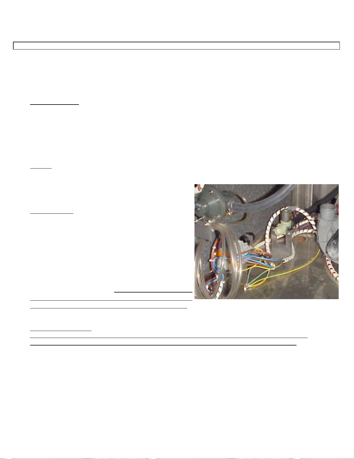
ELECTRICAL
A 208-240 volt, 60 Hz, Single Phase circuit is required for this
unit. Check the rating plate on the machine for amp draw. In
spite of the fact that the rating plate shows 208 volts, the unit is
designed function properly on 208 volts to 240 volts. The
terminal block is located in the base of the machine and can be
accessed from the front. Pass the cable through the cable strain
relief at the back and connect the wires to the terminals LI
(brown wire), L2 (blue wire) & Ground (yellow & green wire).
There should be sufficient cable length to permit the machine
to be pulled out for service. DO NOT TURN ON THE
POWER TO THE MACHINE UNTIL THE WATER
SUPPLY & DRAIN LINES HAVE BEEN CONNECTED.
IMPORTANT NOTE
Reasonable access to and around the machine for service must be provided. Disconnecting of hard
plumbing or removal of counter tops or cabinets, e tc.. for servicing is not covered by warranty.
* - not supplied
Page 3
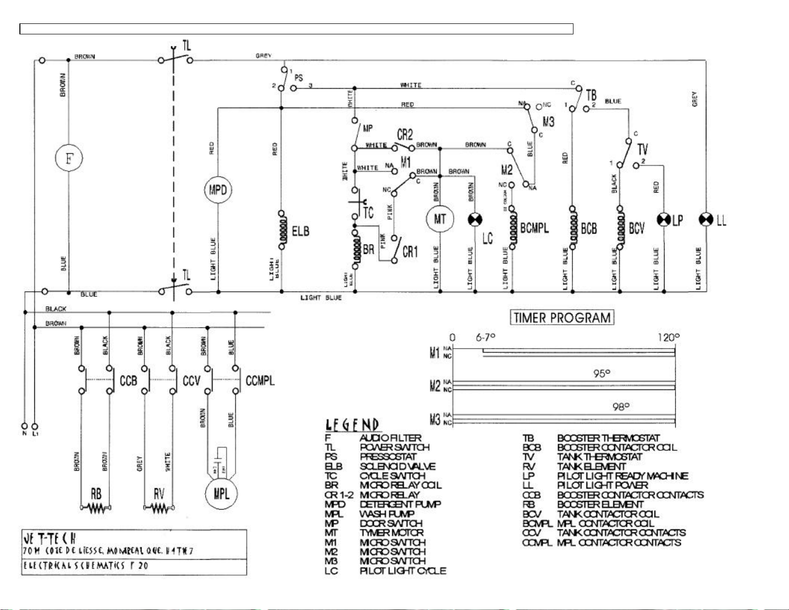
F-20 ELECTRICAL DIAGRAM
Page 4

F20 EXPLODED VIEW
Page 5

F20 EXPLODED VIEW
Page 6

F-20 PARTS LIST
10284 HANDLE 12055 SCREW
10298 PUMP FILTER 12057 HANDLE SOCKET
10342 CONNECTOR DIAMETER 6,5 12072 NUT
10347 CONNECTOR 12073 PLUG
10350 CONNECTOR 12077 HANDLE SOCKET
10351 CONNECTOR 12084 WASH/RINSE ARM
10404 MOTOR MOUNT 12129 DISK
10409 ROD 12131 RUBBER-CARRIER
10415 NUT FOR DOOR SWITCH 12400 F20 JET-TECH DECAL
10421 SMALL SQUARE 15006 PIVOT
10431 NUT 15008 NUT GUIDE
10433 NUT 15016 PIVOT SUPPORT
10435 NUT 15017 DRAIN PLUG
10438 SPACER 15019 KIT SUPPORT + EXTENSION
10446 RINSE AID FILTER 15021 TENSION ROD DOOR
10458 NUT 15022 GUIDE TENSION ROD DOOR
10470 SPRING 15023 BLOCK TENSION ROD DOOR
10471 SPRING 15030 KIT SUPERIOR SUPPORT ARM
10473 SPRING 15545 TUBE
10479 BUFFER 15547 SPACER FOR PIVOT
10489 PIVOT 15572 DOOR
10493 PIVOT 15574 RIGHT BASKET GUIDE
10503 ADJUSTABLE FOOT 15575 LEFT BASKET GUIDE
10523 HANDLE SOCKET 15576 SQUARE
10528 AIR TRAP 15585 BOOSTER TANK
10529 TUBE 15588
10552 PLATE 15690 SURFACE FILTER WITH HOLE
10565 HANDLE SOCKET 15691 SURF. FILTER WITHOUT HOLE
10569 DISK 15692 FRONT GUIDE SURF. FILTER
10576 NUT + RUBBER - CARRIER SOLENOID V. 15693 REAR GUIDE SURF. FILTER
10591 WASHER 15694 CENTRAL GUIDE SURF. FILTER
10598 SQUARE 15705 SQUARE MICROSWITCH
10609 SPACER 15706 SQUARE RIGHT GUIDE
11351 BUSHING 15707 SQUARE LEFT GUIDE
11998 NUT 15741 TUBE
12007 SUPPORT 15742 TUBE
12008 SUPPORT 15745 WASH TANK
12009 HUB 15746 BASE
12010 PLUG 15747 RIGHT UPPER SIDE
12011 RIGHT RINSE ARM 15748 LEFT UPPER SIDE
12012 SUPERIOR RINSE ARM 15749 REAR UPPER PANEL
12013 PLUG 15750 REAR PANEL
12014 RINSE JET 15751 REAR LOWER SIDE
12015 RINSE JET INSERT 15752 RIGHT LOWER SIDE
12016 WASH ARM 15753 LEFT LOWER SIDE
12017 PIVOT 15754 TOP
12019 PLATE 15757 CROSS MEMBER
12020 NUT 15914 PANEL F20 JET-TECH
12021 CONNECTOR 15972 PANEL F20 JET-TECH
12040 MANIFOLD 20010 LENS
12048 PIVOT 20017 FIXING CABLE
12049 DOOR HOOK 20018 FILTER
12050 DOOR CATCH 20025 TIMER BRACKET
12051 SCREW 20042 LIGHT
12052 SPRING 20044 POWER SWITCH
12054 DOOR CATCH BODY 20058 PRESSURE SWITCH
Page 7

F-20 PARTS LIST
20075 TANK ELEMENT 400V 4000W 60200 NUT
20105 CONTACTOR 220/240V 50/60Hz 60202 NUT
20108 THERMOMETER DOUBLE SCALE 60203 NUT
20119 RINSE THERMOSTAT 60204 NUT
20132 TERMINAL 60208 NUT
20133 PLATE 249--116 60210 NUT
20134 TERMINAL 281-313 60212 NUT
20135 STAPLE 60215 NUT
20199 RINSE AID PUMP 60217 NUT M5
20518 TIMER 3'22" 60HZ 60231 WASHER
20519 CYCLE START BUTTON 60232 WASHER
20532 TERMINAL BLOCK 400V 60233 WASHER
20534 CONTACTOR 220V 60Hz (17A) 60234 WASHER
20548 DOOR MICROSWITCH UL F 18 60235 WASHER
20569 SOLENOID VALVE 1A 240V 60Hz UL 60238 WASHER
20570 THERMOSTAT 75° C 60242 WASHER
20574 BOOSTER ELEMENT. 220V 6000W 60243 WASHER
21434 WIRING HARNESS F20 JET-TECH 60244 WASHER
30049 PER RACK 20"X20" 60258 BALL
40230 MOTOR PUMP 220V 0.75HP 60Hz 60555 HOSE
60003 GASKET 60563 HOSE
60004 GASKET 15x10x2 60565 HOSE
60008 GASKET
60009 GASKET
60010 0 RING
60012 GASKET
60017 GASKET
60050 0 RING
60055 0 RING
60060 0 RING
60071 0 RING
60072 0 RING
60073 0 RING
60074 0 RING
60076 0 RING
60078 CLAMP
60079 CLAMP
60081 CLIP
60083 CLIP
60084 CLIP
60102 SCREW
60103 SCREW
60107 SCREW
60109 SCREW
60113 SCREW 5MAX15
60119 SCREW
60130 SCREW
60132 SCREW
60135 SCREW
60137 SCREW
60139 SCREW
60160 SCREW
60162 SCREW
60166 SCREW
60180 SCREW
60191 SCREW
 Loading...