

Page 1
F 1 6 F16 DP
Page 2
F-16 / F-
16DP INSTALLATION
This glasswasher must be installed on a level, rigid, nonflammable surface. Ensure that the machine is level by installing the
feet (shipped in the wash tank of the machine) and adjusting the leveling. Be sure to provide adequate space for water, drain
and electrical connections.
WATERSUPPLY
A 1/2" - 140°F (60°C) hot water line with 30 PSI flow pressure and shut-off valve is required. A pressure reducing valve*
may be required. The water inlet valve is located at the base of the machine and can be accessed from the front. A 1/2'
flexible supply hose* is recommended from the shut-off valve to the water fill valve on the dishwasher to facilitate
maintenance and servicing of the machine. A 90° elbow adapter for the water inlet valve is furnished with the machine and
can be found in the wash tank with the adjustable feet. There should be sufficient hose length to permit the machine to be
pulled out for service.
DRAIN
•F-16: This glasswasher has a gravity drain. Maximum height of the floor drain should not exceed 4" (10cm).
• F-16 DP: This glasswasher is equipped with an automatic drain pump that will pump the drain water to a maximum height
of 36" (0.9 meter). Drain pump equipped machines have a white button on the control panel beside the green power button.
DRAIN PUMP MODELS ARE FACTORY BUILT. GRAVITY DRAIN UNITS CANNOT BE CONVERTED TO
PUMPED DRAIN UNITS.
1" ID flexible drain hose* is recommended to facilitate maintenance and servicing of the machine. It is important not to
reduce the size of this hose. A 1" check-valve* is required on drain pump equipped models. There should be sufficient
hose length to permit the machine to be pulled out for service.
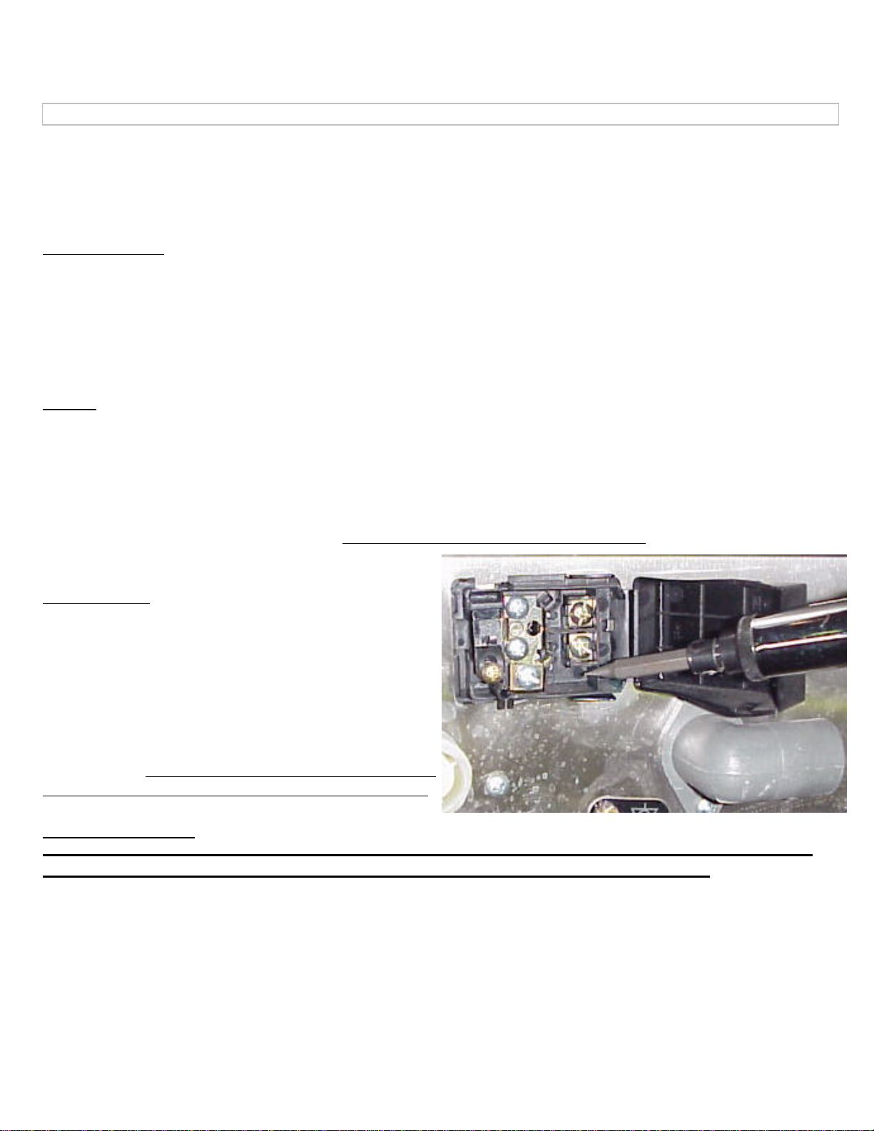
ELECTRICAL
A 208-240 volt, 60 Hz, Single Phase circuit is required for
this unit. Check the rating plate on the machine for amp draw.
In spite of the fact that the rating plate shows 208 volts, the
unit is designed function properly on 208 volts to 240 volts.
The terminal block is located at the back, base of the ma chine.
Open the cover, pass the cable through the cable strain relief
and connect the wires to the LI, L2 & Ground. There should
be sufficient cable length to permit the machine to be pulled
out for service. DO NOT turn on the power to the machine
until the water supply & drain lines have been connected.
IMPORTANT NOTE
Reasonable access to and around the machine for service must be provided. Disconnecting of hard
plumbing or removal of counter tops or cabinets, etc.. for servicing is not covered by warranty.
* - not supplied
Page 3
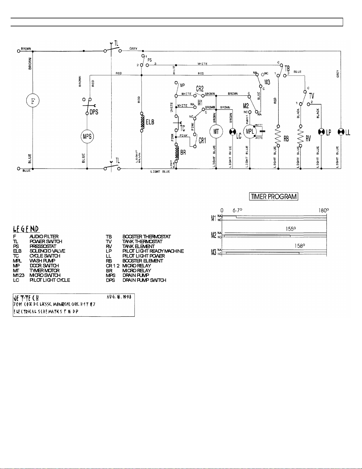
F-16DP ELECTRICAL DIAGRAM
Page 4

F-16 ELECTRICAL DIAGRAM
Page 5

F-16 EXPLODED VIEW
JET-TECH F-16
Page 6

F-16 EXPLODED VIEW
JET-TECH F-16
Page 7

F-16 / F-16DP PARTS LIST
10275 OVERFLOW PIPE 12076 MANIFOLD
10295 TANK FILTER 12131 RUBBER-CARRIER
10342 CONNECTOR DIAMETER 6,5 12168 RUBBER-CARRIER
10344 CONNECTOR 12169 WASH/RINSE ARM
10346 CONNECTOR 12170 RIGHT RINSE ARM
10349 CONNECTOR 12171 LEFT RINSE ARM
10401 MOTOR MOUNT 12174 WASH ARM
10415 NUT FOR DOOR SWITCH 12359 F 16 JET-TECH DECAL
10425 NUT 12437 F 16 (98) JET-TECH DECAL
10426 NUT 15006 PIVOT
10430 NUT 15007 PIVOT SUPPORT
10431 NUT 15008 NUT GUIDE
10435 NUT 15018 KIT SUPPORT + EXTENSION
10458 NUT 15519 TUBE FOR PRESSURE SWITCH
10470 SPRING 15547 SPACER FOR PIVOT
10471 SPRING 15549 BOOSTER TANK
10472 SPRING 15552 BRACKET
10473 SPRING 15559 CROSS MEMBER
10475 SPRING 15562 SMALL SPRING
10479 BUFFER 15563 TUBE
10489 PIVOT 15564 TUBE
10493 PIVOT 15565 TUBE
10502 ADJUSTABLE FOOT 15601 TUBE DP
10523 HANDLE SOCKET 15631 DRAIN PUMP BRACKET
10528 AIR TRAP 15650 FILTER DRAIN PUMP
10552 PLATE 15660
10556 FAIR LEAD 15661
10565 HANDLE SOCKET 15663
10569 DISK 15664 RIGHT BASKET GUIDE
10576 NUT + RUBBER -- CARRIER SOLENOID V. 15665 LEFT BASKET GUIDE
10591 WASHER 15668
11351 BUSHING 15669 HANDLE
11404 FILTER 15676
11409 ROD FILTER 15677
11998 NUT 15705 SQUARE MICROSWITCH
12007 SUPPORT 15706 SQUARE RIGHT GUIDE
12009 HUB 15707 SQUARE LEFT GUIDE
12010 PLUG 15732 CONTROL PAN ELF 16/1 DP JET-TECH
12012 SUPERIOR RINSE ARM 15735 ELEMENT COVER
12013 PLUG 15928
12014 RINSE JET 15929
12015 RINSE JET INSERT 15930 DOOR
12017 PIVOT 15931 RIGHT LAT. PANEL
12019 PLATE 15932 LEFT LAT. PANEL
12020 NUT 15934 PANEL
12021 CONNECTOR 15935 TOP
12034 TUBE 15945 CONTROL PANEL
12040 MANIFOLD 15992 CONTROL PANEL 2 BUTTONS THERMO
12048 PIVOT 20010 LENS
12049 DOOR HOOK 20018 FILTER
12050 DOOR CATCH 20042 LIGHT
12051 SCREW 20045 TERMINAL BLOCK
12052 SPRING 20053 PRESSURE SWITCH
12053 PLATE 20065 POWER SWITCH
12054 DOOR CATCH BODY 20067 RELAY 12A 230V
12055 SCREW 20069 BOOSTER ELEMENT 230V 2400W
Page 8

F-16 / F
-
16DP PARTS LIST
20070 WASH ELEMENT 230V 2000W 60160 SCREW
20108 THERMOMETER DOUBLE SCALE 60161 SCREW
20119 RINSE THERMOSTAT 60162 SCREW
20130 TERMINAL 60164 SCREW
20131 TERMINAL PART 60180 SCREW
20149 POWER SWITCH DP 60200 NUT
20190 FIXING CABLE 60201 NUT
20199 RINSE AID PUMP 60202 NUT
20518 TIMER 3'22" 60HZ 60203 NUT
20519 CYCLE START BUTTON 60204 NUT
20548 DOOR MICROSWITCH U L F 18 60205 NUT
20565 CAPACITOR 10MF 240UL 60208 NUT
20568 SOLENOID VALVE 2A 240V 60HZ 60210 NUT
20570 WASH THERMOSTAT 60212 NUT
21420 WIRING HARNESS F 16/1 60215 NUT
21429 WIRING HARNESS F 16/1 DP 60231 WASHER
30012 GLASS BASKET 16x16x5 60232 WASHER
30026 CUTLERY HOLDER 2 COMP. 60233 WASHER
30035 SAUCER INSERT 60234 WASHER
30116 GLASS BASKET 4 DIVISIONS 16x16 60235 WASHER
40229 DRAIN PUMP 60Hz 60238 WASHER
40242 MOTOR PUMP 220V 60HZ 60242 WASHER
60003 GASKET 60244 WASHER
60004 GASKET 60245 WASHER
60005 GASKET 60258 BALL
60008 GASKET 60555 HOSE
60009 GASKET 60563 HOSE
60012 GASKET 60565 HOSE
60050 0 RING
60055 0 RING
60060 0 RING
60061 0 RING
60063 0 RING
60071 0 RING
60072 0 RING
60073 0 RING
60074 0 RING
60076 0 RING
60078 CLAMP
60079 CLAMP
60081 CLIP
60082 CLIP
60083 CLIP
60089 CLIP
60102 SCREW
60103 SCREW
60105 SCREW
60107 SCREW
60109 SCREW
60119 SCREW
60130 SCREW
60131 SCREW
60132 SCREW
60135 SCREW
60137 SCREW
60139 SCREW
 Loading...