

Page 1
JET TECH TECHNICAL MANUAL
737E VER1.02
2015/12
1
Page 2
Contacts
Technical Support 1-888-275-4538
Robert Marsolais Service Manager 225 robert@mvpgroupcorp.com
Alan Gallagher Service Consultant 214 alan@mvpgroupcorp.com
Jonathan Menard Service Consultant 230 jonathan@mvpgroupcorp.com
Richard M. Hiller Special Projects Manager 211 richard@mvpgroupcorp.com
service @mvpgroupcorp.com
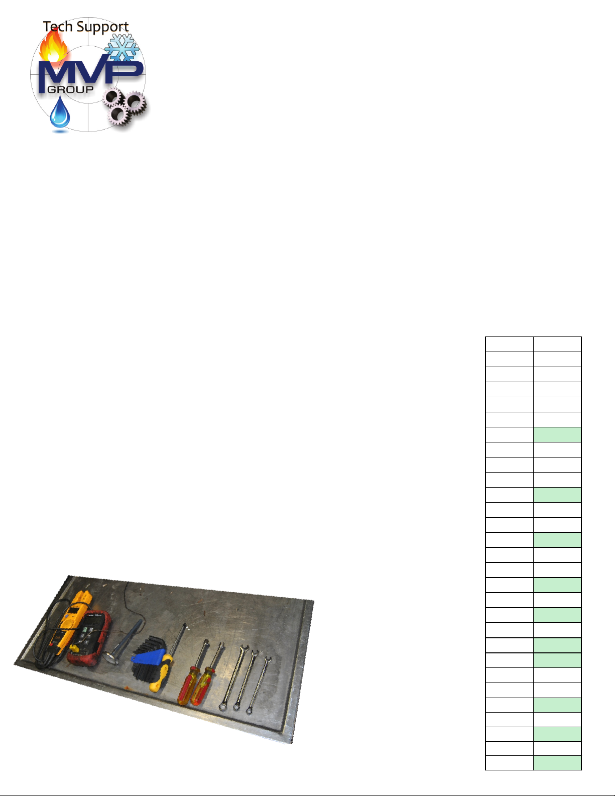
Tools
Some of the tools you will need
to repair and service the 737e.
Volt Meter
Temperature meter
Allen Keys (Metric)
Phillips screw driver
Nut drivers (Metric)
Wrenchs (Metric)
(inches)
2
US Metric
(mm)
1/8 3.18
5/32 3.97
4
3/16 4.76
5
13/64 5.16
7/32 5.56
15/64 6.05
6
1/4 6.35
17/64 6.75
7
9/32 7.14
5/16 7.94
8
11/32 8.73
9
3/8 9.53
10
11
7/16 11.11
15/32 11.91
12
1/2 12.7
13
17/32 13.49
14
Page 3
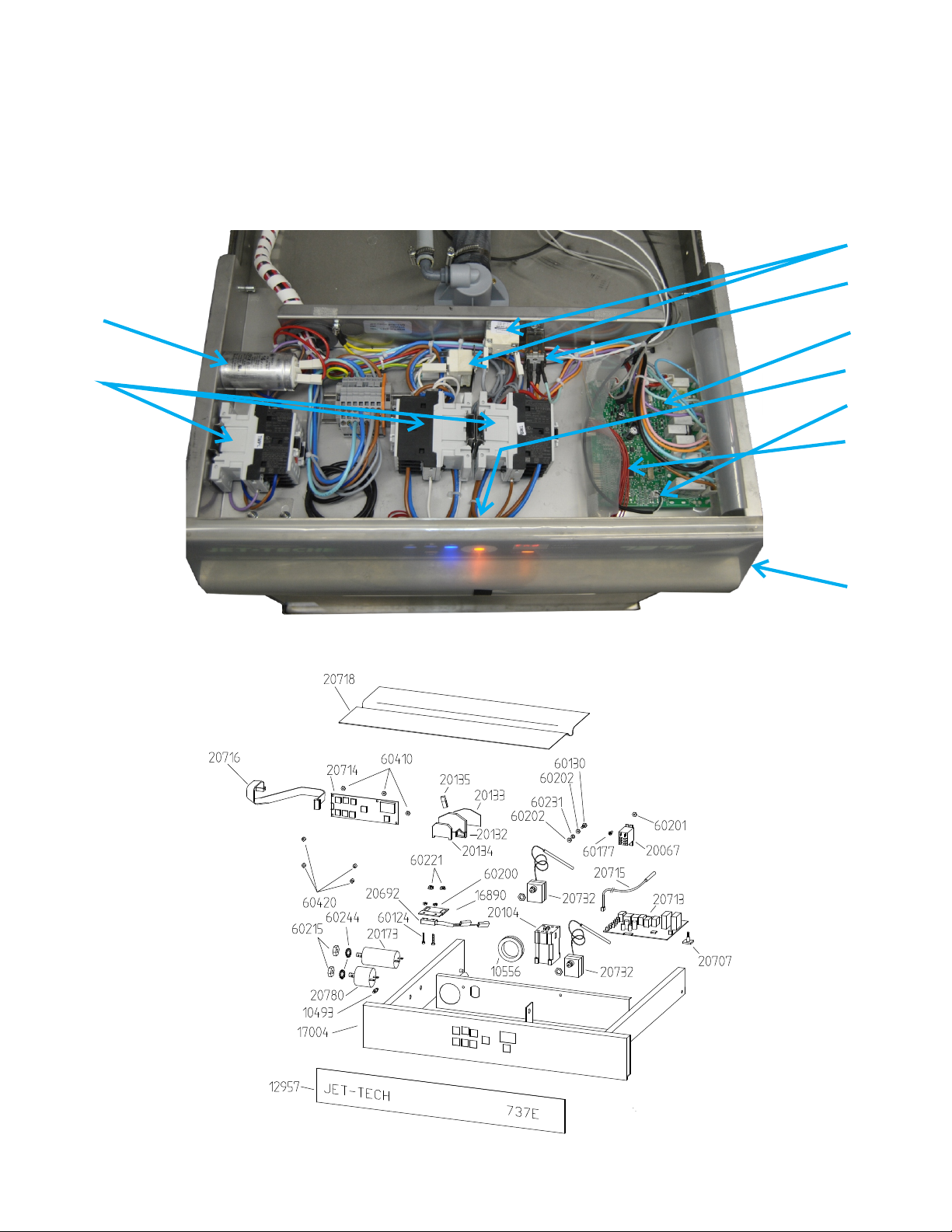
Top of 737e
20732
20067
20173
20104
20713
20714
20715
20716
20718
3
Page 4
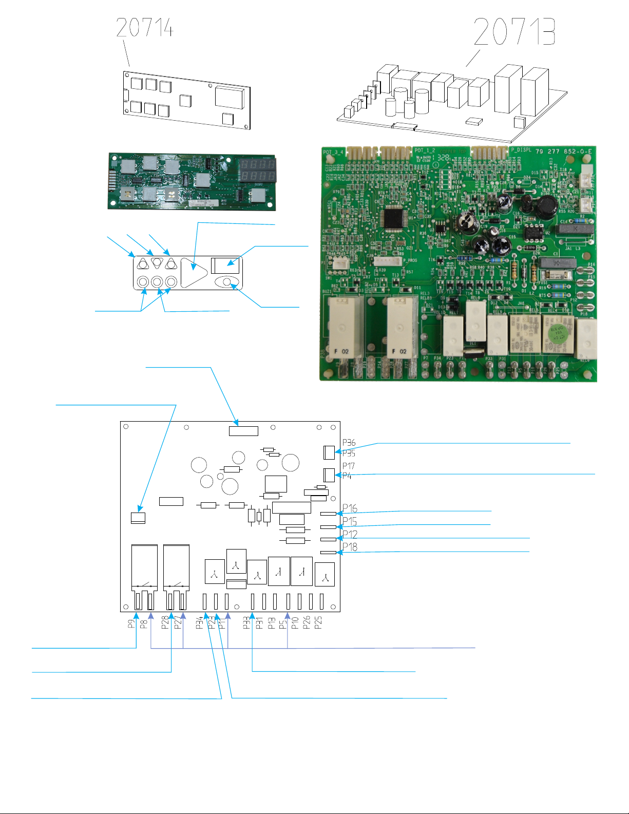
Wash Cycles
4m 3m 2m
Cycle Start
Display
Unused
Touch-Pad
Final Rinse Probe
Drain
ON/OFF
temperature probe Wash Tank
Temperature probe rinse booster
Power line L1
Power line L2
Door switch signal
Water level signal
Booster Heat
Wash Heat
Incoming Water (chemicals)
Power Line L2
Wash
Drainage
4
Page 5
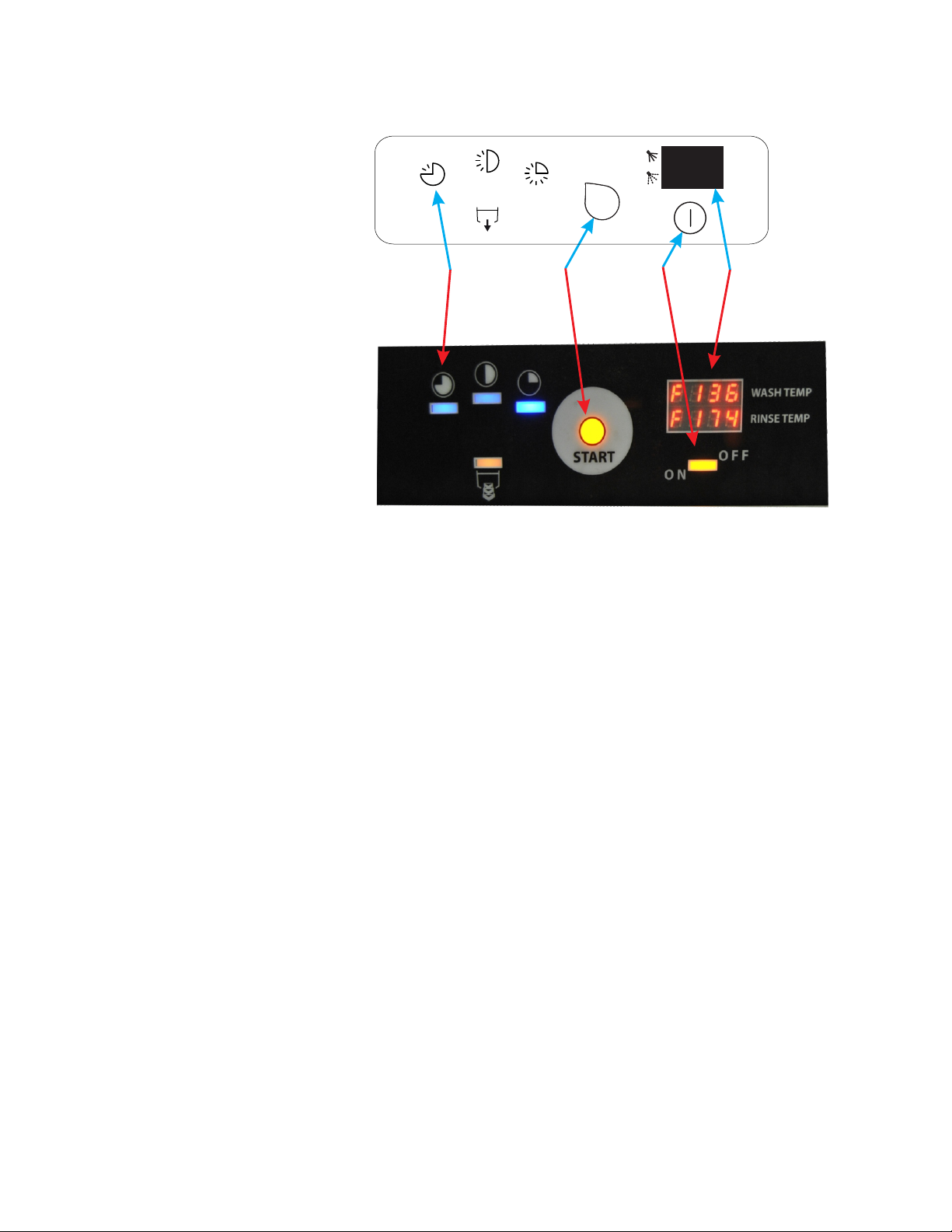
ELECTRONIC BOARD PROGRAMMING
START
C
B
A
D
MENU ACCESS
Level 1
Level 1 access will allow you to change the first 4 settings.
1 TURN THE MACHINE ON AND OFF BY PRESSING BUTTON A.
(IF THE MACHINE IS ALREADY ON, TURN IT OFF BY PRESSING BUTTON A)
2 PRESS BUTTON B SEVEN (7) TIMES WITHIN (10) SECONDS FROM TURNING OFF
MACHINE.
3 PRESS AND KEEP PRESSING BUTTON C ONCE QUICKLY.
“P-00 STOP” WILL BE ON THE DISPLAY.
MODIFY PARAMETERS
1 SELECT A PARAMETER BY SCROLLING THROUGH THE MENU WITH BUTTON B.
2 PRESS BUTTON C TO ENTER INTO THE PARAMETER MODIFICATION.
3 PRESS BUTTON B TO MODIFY THE PARAMETER WITH AVAILABLE OPTIONS
AND BUTTON C TO CONFIRM THE MODIFICATION.
ONCE YOU CONFIRM THE MODIFICATION, YOU RETURN TO POINT 1 WITH THE OPTION TO
SELECT ANOTHER PARAMETER BY SCROLLING THROUGH THE MENU WITH BUTTON B.
5
Page 6
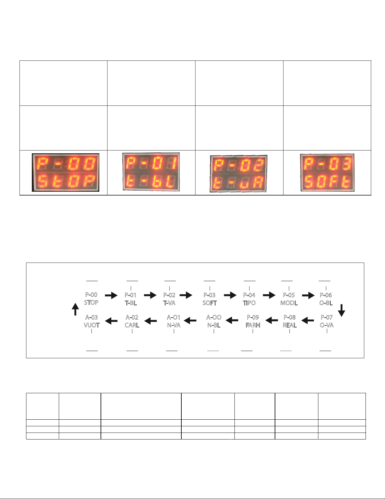
P-00
STOP
P-01
T-BL
P-02
T-VA
P-03
SOFT
Thermostop
0= not active
1=active
default:0
Temperature boiler
Min 60C 140F
Max 95C 200F
Default 85C 185F
Temperature Tank
Set to 70C 160F
Default 60C 140F
Soft start
0= not active
1= active
default: 1 ,set to 0
THERMOSTOP
0 = not active
1 = active
∗DEFAULT 0=NOT ACTIVE
TEMPERATURE BOILER
Min 60°C
Max 95°C
∗DEFAULT 85°C
TEMPERATURE TANK
Min 40°C
Max 65°C
∗DEFAULT 60°C
SOFT START
0 = not active
1 = active
∗DEFAULT 1=ACTIVE
TYPE MACHINE
Min 1
Max 2
∗DEFAULT SEE CHART
MODEL MACHINE
Min 1
Max 27
∗DEFAULT SEE CHART
OFFSET TEMPERATURE BOILER
Min - 20°C
Max +20°C
∗DEFAULT 0°C
AVAILABLE PARAMETERS
P04
(DISPLAY)
2 8
4 31 70 + 120 + 180 + 240
MAX DRAIN TANK
Min 1 min
Max 20 min
∗DEFAULT 2 min
DON’T MODIFY
P05
(DISPLAY)
MAX LOADING TANK
Min 1 min
Max 20 min
∗DEFAULT 10 min
DON’T MODIFY
MODEL
727E / 737E
757E
MAX HEATING TANK
Min 1 min
Max 60 min
∗DEFAULT 45 min
DON’T MODIFY
120 + 180 + 240 sec
CYCLE
6
MAX HEATING BOILER
Min 5 min
Max 60 min
∗DEFAULT 30 min
DON’T MODIFY
sec
TEMPERATURE UNITS
FAR = FAHRENHEIT
CEL = CELSIUS
∗DEFAULT CEL=CELSIUS
REAL TEMPERATURE
0 = FILTERED
1 = REAL
∗DEFAULT 0 = FILTERED
DON’T MODIFY
OFFSET TEMPERATURE TANK
Min - 20°C
Max +20°C
∗DEFAULT 0°C
DON’T MODIFY
DRAIN PUMP
YES
Page 7

Level 2
P-04
TIPO
P-05
MODL
P-06
O-BL
P-07
O-VA
TYPE OF MACHINE
SET AT 2
MODEL OF MACHINE
SET AT 8
OFFSET
TEMPERATURE BOILER
! DO NOT CHANGE
SET AT 0
OFFSET
TEMPERATURE TANK
! DO NOT CHANGE
SET AT 0
PP-0
P-01
P-02
P-03
P-08
REAL
P-09
FARH
A-00
N-BL
A-01
N-VA
REAL TEMPERATURE
0= FILTERED
1= ACTUAL
DEFAULT=0
TEMPERATURE UNIT
0=CELSIUS
1= FAHRENHEIT
SET TO 1
MAX HEATING TIME
FOR BOILER
MIN 5 MIN
MAX 60 MIN
DEFAULT 30 MIN
MAX HEATING TIME
FOR TANK
MIN 1 MIN
MAX 60 MIN
DEFAULT 45MIN
Level 2 access will allow you to change all 14 settings.
1 TURN THE MACHINE ON AND OFF BY PRESSING BUTTON A.
(IF THE MACHINE IS ALREADY ON, TURN IT OFF BY PRESSING BUTTON A)
2 PRESS BUTTON B SEVEN (7) TIMES WITHIN (10) SECONDS
FROM TURNING OFF MACHINE.
3 PRESS AND KEEP PRESSING BUTTON C FOR THREE (3) SECONDS
UNTIL P-00 STOP IS ON THE DISPLAY.
7
Page 8

A-02
CARL
A-03
VUOT
MAX FILL TIME
MIN 1 MIN
MAX 20 MIN
DEFAULT 10 MIN
MAX DRAIN TIME
MIN 1 MIN
MAX 20 MIN
DEFAULT 2 MIN
ntcb
E-01
Booster temperature probe faulty or not connected properly
ntcu
E-02
Tank temperature probe faulty or not connected properly
FILL
E-03
Water fill not completed within allocated time (10 min)
Obstruction in water line, or faulty solenoid valve.
t bo
E-04
Booster temperature limit setpoint reached (+14C/ 57F)
t UA
E-05
Tank temperature limit setpoint reached (+14C/57F)
drA
E-06
Drain problem; Drainage not completed on maximum set time.
Bad drain pump, obstruction in drain line or pump.
bnot
E-07
Maximum booster heating time reached (15min)
unot
E-08
maximum tank heating time reached (30 min)
SErulCE
E-09
Memory error or electronic board damaged
Error Codes
8
Page 9

-PSd--1
-PLd--1
88:88
empty
-r r-
0143
Drain pump test
door closed
d--0 = door open
Wash pump test
door closed
N/A
SALT
OPEN
-rb-
0078
empty
88:88
-rL-
0046
N/A
Booster heater test
temperature in Celsius
Wash Tank Heater test
Temperature in Celsius
-ECd--1
-ERd--1
-Erd--1
-Ebd--1
P-10
door closed
P-13
door closed
P-25
door closed
Solenoid valve
(chemical pumps) test
door closed
Level 3
Level 3 access will allow you test different components.
1 TURN THE MACHINE ON AND OFF BY PRESSING BUTTON A.
(IF THE MACHINE IS ALREADY ON, TURN IT OFF BY PRESSING BUTTON A)
2 PRESS BUTTON C SEVEN (7) TIMES WITHIN (10) SECONDS
FROM TURNING OFF MACHINE.
9
Page 10

10
Page 11

11
Page 12

12
Page 13

13
Page 14

Part Number Description
10342 CONNECTOR DIAMETER 6,5
10349 CONNECTOR
10421 SMALL SQUARE
10422 NUT
10425 NUT
10433 NUT
10435 NUT
10441 SPRING F.BULB PROBE THERMOSTAT
10471 SPRING
10472 SPRING
10479 BUFFER
10493 PIVOT
10502 ADJUSTABLE FOOT
10534 TUBE
10552 PLATE
10556 FAIR LEAD
10598 SQUARE
10609 SPACER
11351 BUSH
11510 TUBE
11543 CONNECTOR
11586 TUBE POMPE VIDANGE 1000-1201
11994 ROD FILTER
11998 NUT
12007 SUPPORT
12008 SUPPORT
12017 PIVOT
12019 PLATE
12020 NUT
12021 CONNECTOR
12022 LID WITH FILTER
12024 CONNECTOR
12025 TUBE
12027 CONNECTOR
12028 NUT
12030 TUBE
12035 TUBE
12037 TUBE
12038 FILTER
12039 FILTER
12048 PIVOT
12049 DOOR HOOK
12050 DOOR CATCH
12051 BUSH
12052 SPRING
12053 PLATE
12054 DOOR CATCH BODY
12055 SCREW
12060 ANTI-VIBRATION
12074 HUB
12076 MANIFOLD
12128 FILTER
12129 DISK
12760 TRANSPARENT FILM 110X150
12957 FILM 737 E JET-TECH
15006 PIVOT
15030 KIT SUPERIOR SUPPORT ARM
15031 KIT INFERIOR SUPPORT ARM
15061 CONNECTOR
15086 GAS SPRING
15088 WASH/RINSE ARM 50-1200
15089 WASH/RINSE ARM
15093 ANTI REFLUX DEVICE X-33
15103 CONNECTOR PROBE TEMPERAT.NSF
15105 PLUG DOOR MICROSWITCH
16029 TUBE F.PRES.SWITCH CF 50 2001
16039 BUFFER FOR FLASK EPDM
16045 TUBE 3/4-3/4 TRAY 600X400
16048 MANOMETER
16053 RUBBER-CARRIER 1/4 GAS
16057 BOYLER 737 BULKHEAD NSF
16073 PLUG NYLON TFT 26X1,5
16074 NUT NYLON 3/4 BLACK RO/3-4 N
16345 SQUARE F.PRESSURE SWITCH 2001
16366 FLASK DET.PUMP DS 400
16666 AIR TRAP STAINLESS STEEL
16679 RUBBER-CARRIER PG13 1/2-18/1"
16754 PIVOT FOR GAS SPRING
16890 SQUARE MAGNET.SWITCH AT 50
16905 RIGHT BASKET GUIDE AT 50
16906 LEFT BASKET GUIDE AT 50
16913 DOOR AT 50
16914 BASEMENT AT 50
16915 RIGHT GUIDE AT 50
16916 LEFT GUIDE AT 50
16919 REAR PANEL AT 50
16920 TOP AT 50
16930 FLASK FOR VALVE NSF
17004 PANEL TS 58 OMEGA ELECTRONICS
17024 TANK AT 50
17025 RIGHT LAT.PANEL AT 50
17026 LEFT LAT.PANEL AT 50
17027 PANEL JET-TECH 737 NSF
17056 FLASK MANOMETER 737 NSF
20017 FIXING CABLE ST 16
20050 FAIR LEAD WITH DIAPHRAGM DG 29
20067 RELAY 12A 230V
20079 BOYLER HEATING ELEM.230V 4000W
20088 TANK HEATING ELEM.230V 2800W
20104 CONTACTOR 220/230V 50/60HZ
20132 TERMINAL
20133 PLATE 249-116
20134 TERMINAL 281-313
20135 STAPLE
20173 CAPACITOR 16
20192 PRESSURE SWITCH
20332 SPIRAL
20336 CLIP
20337 CLIP NYLON
20532 TERMINAL BLOCK CF 50 400V
20552 CONNECTOR AUT.D.DOS.(5X7)
20569 SOLENOID VALVE 1A 240V 60HZ UL
20582 TERMINAL FV110
PARTS LIST
14
Page 15

20589 FILTER FOR AUT.DET.DOSER 5X7
20692 MAGNETIC SWITCH E5121VDA0196
20693 MAGNET M302NCBCNC42
20707 SUPPORT FOR ELECTRONIC CARD
20713 ELECTRONIC CARD POWER
20714 ELECTR.CARD CONTROL AND VIEW
20715 PROBE TEMPERATURE 2 MT ELECTR.
20716 CONNECT.CABLE EL.CARD 7+7 40CM
20718 MYLARD PROTECTION THICKN.0,10
20728 AUTOMATIC DET.DOSER GN202 NSF
20729 AUTOMATIC DET.DOSER GN82B NSF
20732 SAFETY THERMOSTAT 124° WYF 2MT
20741 PROBE NTC 1/4 2MT CONNECTOR
20769 NUT SEKO F.6MM 0000061001
20779 SHRINK TUBING D.6,4
20780 FILTER UL
21616 U BOLT AUT.PERIST.DOSER JET-T.
21700 LOOM 737 E NSF
30049 DISH BASKET 50X50
30105 UNIVERSAL BASKET 50X50
40226 MOTOR PUMP
40293 DRAIN PUMP 60HZ
60003 GASKET
60004 WASHER TEFLON 15X10X3
60007 WASHER TEFLON 15X10X9
60009 GASKET 52X42X6
60010 O RING
60012 GASKET
60050 O RING
60074 O RING
60075 O RING
60076 O RING
60081 CLIP
60082 CLIP
60083 CLIP
60084 CLIP
60089 CLIP
60093 CLAMP
60102 SCREW
60103 SCREW
60109 SCREW
60124 SCREW 3MAX30
60130 SCREW
60131 SCREW 5MAX10
60132 SCREW
60135 SCREW
60137 SCREW
60145 SCREW 6MA X 8
60163 SCREW
60166 SCREW
60177 SCREW 4MAX10
60179 SCREW
60187 SCREW 4MAX10
60191 SCREW 6MAX12
60194 SCREW 4MAX30
60200 NUT
60201 NUT
60202 NUT
60208 NUT
60210 NUT 8MA
60212 NUT
60215 NUT
60221 NUT DIN 6923 5MA
60222 NUT DIN 6923 5MA INOX
60231 WASHER
60234 WASHER
60242 WASHER
60244 WASHER
60250 RING
60410 PLASTIC NUT M3
60420 SPACER NYLON 7X4X6
60540 HOSE POLYAMIDE 5X7 MM
60552 RED HOSE 5X7 X-32/X-33
60553 BLUE HOSE 5X7 X-32/X-33
60556 TUBE FOR DRAIN PUMP
60565 HOSE
60596 BAG
60626 PANEL
60655 PACKAGE F 18/737 JET-TECH
60657 PEDESTAL F 18/737 JET-TECH
60659 EXPANTED 85X10X10X3
60675 EXPANTED 87X42X3 K20
15
Page 16

MANUFACTURERS LIMITED WARRANTY
Jet Tech Systems Corporation (Jet Tech) hereby warrants all new warewashers
bearing the name JET TECH and installed within the continental United States of
America or Canada to be free from defects in material or workmanship, under normal
and regular usage and operation, for a period of one (1) year following the date
of original installation, (unless specified otherwise) but in no event can exceed
eighteen (18) months from the date of shipment from the factory.
If a defect in material(s) or workmanship is detected; or found to exist within
the stated period above, Jet Tech, at its sole discretion, shall either repair or
replace any original equipment manufacturers part which has proven to fail within
the machine; providing that the equipment has not been altered or tampered with in
any manner, has been installed correctly as per the owners manual, and maintained
and operated in complete accordance with this manual.
The labor cost to repair or replace any part proven to be defective, as per above
clause(s), shall be covered by Jet Tech Systems, within the continental United
States of America or Canada; provided that: prior authorization for this labor
was approved by Jet-Tech Systems, the service work was performed by an authorized
Jet Tech service agency; and that this agency installed an original and genuine
Jet Tech part in the machine. Any repair work performed by a non-authorized
service depot remains the sole responsibility of the user, and Jet Tech Systems
will not be held responsible. The installation of any generic part will not be
valid; and therefore voids this warranty. All authorized labor coverage shall be
limited to regular hourly rates only. Any supplemental hourly rates or charges,
such as weekends or emergency premiums remain the responsibility of the user.
Jet Tech Systems Corp. (Jet Tech) hereby states that: warranty travel time shall
be limited to, and without exception, a round-trip total of two (2) hours OR
mileage up to a maximum of one hundred (100) miles round-trip. Any charges
exceeding those stated herein must have prior authorization by the factory.
Exceptions to above warranty are: (A) Damages resulting from shipping, handling
or abuse. (B) Incorrect installation and/or connections. (C) Adjustments or
calibration of any parts. (D) Faults due to lack of regular maintenance or
cleaning of any internal part(s). (E) Replacement of any wearable items such as:
glasswasher curtains, or peristaltic squeeze tubing or gaskets. (F) Excessive
lime, mineral, alkali or hard water conditions and (G) Poor results due to: use of
an incorrect type of detergent (for non-commercial type applications), and
excessive or inadequate water temperature(s) or pressure conditions.
JET TECH SYSTEMS CORPORATION STATES THAT THERE ARE NO OTHER WARRANTIES, EXPRESSED
OR IMPLIED, THAT ARE NOT SET FORTH HEREIN, JET TECH SYSTEMS CORPORATION SHALL
ASSUME NO OTHER RESPONSIBILITY, EITHER DIRECT OR NON-DIRECT, OR BE LIABLE FOR ANY
OTHER OR ADDITIONAL LOSS OR DAMAGE WHETHER BEING DIRECT OR CONSEQUENTIAL, AS A
RESULT OF ITS EQUIPMENT.
16
Page 17

SERVICE CALL REGULATIONS
JET TECH ware washers are warranted as specified in the MANUFACTURERS LIMITED
WARRANTY.
Upon receiving the demand for repairs on a unit, we will create a work order or
Warranty Authorization which will have all the pertinent information. We will
send this form to you as a purchase order for service. We ask that you respect the
times allocated on the form. Should more time is required to complete a service
call, call us and ask for more time. Without proper authorization, your claim for
payment will be delayed.
We will pay for:
1. Labor to replace a defective part, as per the attached Allocated Times Schedule.
2. Travel time, as specified in the MANUFACTURERS LIMITED WARRANTY.
3. JET TECH original replacement parts supplied from service company inventory
We will NOT pay for:
Unauthorized labor charges.
Unauthorized travel charges.
Waiting time. Call for an appointment, if required.
More than one man on a service call.
Travel time exceeding the MANUFACTURERS LIMITED WARRANTY.
More than one service call for the same problem.
Adjustment or calibrations, as specified in the MANUFACTURERS LIMITED WARRANTY.
Replacement of small items (pilot light, screens, jets).
Cleaning or regular maintenance.
Overtime or weekends charges (time and a half, or more)
Problems due to improper installation.
Problems due inadequate or improper use of the equipment.
Problems due to improper water supply temperature or inadequate/excessive water pressure.
Problems due to inadequate/excessive electric supply.
Disconnecting of hard plumbing or removal of counter tops, etc.
We are here to help you with diagnostic or service problems.
Call us toll free at 1-888-275-4538, extension 611 for assistance. After office hours assistance
is also available by dialing the extension 411 or *411. Our email is service@mvpgroupcorp.com.
All paperwork related to warranty work can be sent by email to warranty@mvpgroupcorp.com .
Other contact information is available at www.mvpgroupcorp.com .
Our standard procedure is to invoice all parts shipped at $0 for WARRANTY REPAIRS regardless what
the amount shows on the work order. All defective parts should be kept for 90 days. After this
period, the parts can be discarded.
YOUR INVOICE MUST INCLUDE THE FOLLOWING INFORMATION:
1. Warranty Repair Authorization Number.
2. Model and serial numbers.
3. Problem reported.
4. Detailed description all charges including dates, hours worked and work done.
5. Reason for part failure.
6. Indicate the general state of the equipment, cleanliness and if abuse is apparent.
We expect that your work is warranted by your company for at least 90 days.
17
Page 18

COVER PAGE
2 CONTACT
3 TOP OF DISHWASHER
4 ELECTRONICS
5 PROGRAMMING
6 PROGRAMMING (CONT)
7 PROGRAMMING (CONT)
8 PROGRAMMING (CONT)
8 ERROR CODES
9 LEVEL 3, TESTING
10 EXPLODED VIEW
11 EXPLODED VIEW (CONT)
12 EXPLODED VIEW (CONT)
13 EXPLODED VIEW (CONT)
14 PARTS LIST
15 PARTS LIST (CONT)
16 WARRANTY
17 WARRANTY REGULATION
18 LAST PAGE
18
 Loading...