

1
INSTALLATION AND OPERATING INSTRUCTIONS
EuroJet
Eurojet Swimjet Instructions
www.agbudget.co.uk Luxury Swimming Pool Equipment at Budget Prices

16
GB
Preface
Your unit has been built in accordance with the latest state of the art, and is safe. However, the unit can be
dangerous if it is operated by persons who have not received the necessary training or instruction, or if it is used
improperly. Therefore, everyone entrusted with the task of installing the unit, setting it into operation, operating,
maintaining and repairing it, must read and understand the Operating Instructions and - especially - the Safety
Instructions. Before using the unit for the first time, you and/or your personnel should definitely receive instructions from the specialist consultant. If, contrary to expectations, technical defects occur in your unit, please
contact the customer service department or your dealer.
LIST OF CONTENTS PAGE
1 SAFETY INSTRUCTIONS ...................................................................................................................... 16-17
2 INST ALLING THE WALL NICHE IN CONCRETE SHUTTERED POOLS ..............................................18-19
3 FINAL ASSEMBLY INSTRUCIONS........................................................................................................ 20-21
4 OPERATION / INFORMATION FOR THE USER OF THE UNIT ............................................................. 23-27
4.1 BEFORE STARTING............................................................................................................................ 22
4.2 FIRST TIME OPERA TION.................................................................................................................... 22
4.3 STARTING THE UNIT .......................................................................................................................... 23
4.4 STRENGTH OF THE JET .................................................................................................................... 23
4.5 MASSAGE....................................................................................................................................... 23-24
4.6 SWIMMING AGAINST THE CURRENT ................................................................................................ 24
4.8 WINTERIZATION ................................................................................................................................. 24
4.8 AGAIN OPERATION ............................................................................................................................ 24
5 SERVICE...................................................................................................................................................... 24
6 FITTING INSTRUCTION FOR HANDGRIPS ...............................................................................................25
7 INFORMATION FOR THE ELECTRICIAN .............................................................................................. 26-27
1 SAFETY INSTRUCTIONS
1.1 Before Setting into Operation
Before installation and setting into operation, the Safety Instructions and the Operating Instructions
must be carefully read and observed. You must definitely comply with the requirements of the uwe
company and of the standards authorities.
1.2 Setting the Unit into Operation for the First Time
Before the unit is set into operation, the local safety regulations and the Saf ety Instructions must always be complied
with.
1.3 Sources of Danger
Warning!
The JETSTREAM system forces up to 700 litres of water per min ute into the pool through the nozzle. If all of
this enormous force is used for massage, it can cause injuries to muscles and to connectiv e tissue, as well as
internal injuries. Because of the reduced electrical resistance of the human body in swimming pools and the
resulting increased probability of the occurrence of dangerous currents in the body , increased safety requirements
are imposed on the electrical installation.

17
Therefore, you must definitely observe the following Safety Instructions:
The JETSTREAM has substantial power. Before massage, you must definitely reduce the
pressure.
Do not utilize full thrust against soft parts of the body.
Switch off pump before adjusting angle of nozzle.
For large-area massage, reduce the strength to half thrust.
In order to attach and detach the massage fitting switch off the pump.
T o massage a single part of the body , grip the massage hose firmly . When using the hose keep
a distance to those parts of the body that require massaging.
Do not approch the suction filter with long hair unless tied back.
Before putting the massage hose on or taking it off, switch off the pump.
For point massage, hold the nozzle of the massage hose firmly in your hand under water . Guide
the nozzle of the massage hose over the required places but at some distance from them.
Do not dive to the intake screen (if there is one) with long, unrestrained hair.
For requirements regarding the appropriate electrical installation, please see „Information for the Electrician“,
as per part 7. P arts of the equipment that contain electrically live parts must be inaccessible to persons using
the pool. Units and unit parts containing electrical components must be installed or fixed in such a wa y that they
cannot fall into the water . Units of enclosure class I must be permanently connected to permanently laid cables.
1.4 Proper Operation
All units are intended soleley for operation in co vered swimming pools and in open-air swimming pools with a
water temperature up to 35°C. The units are suitable for installing and operating in installations and rooms in
areas 1 and 2 as per EN-60335-2-41. The pump is normally installed in the walkw ay behind the pool wall, b ut it
must be ensured that the environment is dry and that the motor is protected by a suitably sized floor drain to
prevent flooding. The control panel should be installed either in a dry walkwa y or in an adjacent room, if possible
higher than the water lev el. Any kind of use other than the intended use is improper . The manuf acturer will not
accept liability for any damage or injury resulting from improper operation; the user alone must bear this risk.
Proper operation also includes compliance with the operating, maintenance and repair conditions specified by
the manufacturer . Maintenance work, repair work and suchlike may only be perf ormed by authorised persons.
The units may only be used by persons who are familiar with them and who have been informed about the
dangers. The relevant regulations for the prevention of accidents and the other generally recognised rules
relating to safety and to occupational medicine must be complied with. If unauthorised modifications are made
on the units, the manufacturer will not accept liability f or an y resulting damage or injury.
1.5 Product Liability
The user’s attention is e xpressly dr awn to the f act that the unit ma y only be operated in the proper manner. If it
is operated in an improper manner, the user must bear sole responsibility. In such cases, therefore, the
manufacturer cannot accept any liability.
1.6 Procedure in an Emergency
Leave the water immediately, switch off the electrical supply to the unit by operating the main power switch or
circuit-breaker , and secure the unit to prevent it from being switched on again without authorisation.
1.7 Explanation of the Danger Symbols
Warning!
In these Operating Instructions, we have used this symbol to mark all texts which relate to
your safety. Please pass all safety instructions on to other users too.
In these Operating Instructions, we have used this symbol to mark all texts containing
instructions that are necessary for functional reasons. Please be sure to obey these instructions
in order to avoid damage to the unit.
18
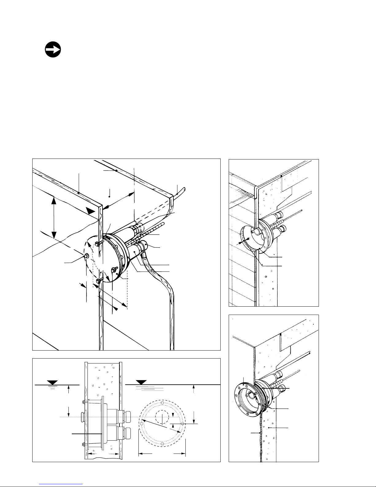
2 INSTALLING THE WALL NICHE IN CONCRETE SHUTTERED POOLS
Installation (fig. 1)
Position the wall niche ensuring that the read label “Oben” (top) is on top.
Viewed from inside the pool, the suction duct is on the v ertical middle axis above the center of the housing, the
pressure duct at the bottom on the right side.
The front of the wall niche must be set flush with the face of the wall concrete . In case of a liner/concrete pool,
the wall niche may project in order to compensate for the cement render of liner insulation thickness. It is
advisable to make provision for protecting tube by placing in protective conduit or through adjacent cable/
ventilation ducts.
• Tile plan (fig. 2)
Render and tile to inner edge of wall niche.
• Pools with plastic liner (fig.3)
Proceed as shown in fig. 3
shutterung
concrete
air inlet tube 4 m long
label
“top”
presure duct
prodective sleeve for
pneumatic tube for wall
thickness up to 50 cm
special nipple do
not remove
suction duct
wall niche
shuttering
screw
M8 x 50 plasitic
24
23,7 - 38,7
(optimal 28,7)
Ø 28,9
Ø 31
25,6
water level
cut into
edge of yellow
protective cover
and remove
before rendering
1
2
3
Ø 31
20-35
(opt. 25)
Ø 25,6
24
23,7 - 38,7
(optimal 28,7)
3,7
water level
water level
metal frame
render and tile
to inner edge
max thickness
render and
tile 5 cm
one rubber
gasket to
front and
back of
liner
liner
concrete
gasket
clamping
frame

19
Installing the wall niche in steel, aluminium and polyester pools
Installing the wall niche in deck level pools with overflow channel
Ø 31
Ø 25,6
23,7 - 38,7
(optimal 28,7)
3,7
20-35
(opt. 25)
24
~13,5
~8
~42
~35
Ø 31
20-35
(opt. 25)
Ø 25,6
3,7
24,0
Ø 23,5
8
x
4
5
°
=
3
6
0
°
45°
Ø 0,9
dimensions in cm
dimensions in cm
water level water level
nozzle center line
clamping frame
air inlet tube for air
suction end part to be
installed 5 - 10 cm
above water level
pool wall
sunk screw
M 8 x 35
use clamping
frame for cutting
and drilling
label
top
gasket
concrete max.
wall niche
suction duct
protective
sleeve for
pneumatic tube
water level water level
air inlet tube for air
suction end part to be
installed 5 - 10 cm
above water level
suction duct
protective sleeve
for pneumatic tube
nozzle center
line
wall niche
gasket
shuttering
use drilling template
for drills in the
shuttering
air inlet
label „top“
20
3 FINAL ASSEMBLY INSTRUCIONS
INSTRUCIONS FOR AUTHORIZED PERSONS ONLY
Before installation
The safety instructions must be read carefully before installation. You must definitely fulfil the requir ements stated
by the uwe company and by the standars authorities. If the instructions are not observed, the installation engineer
shall bear the sole responsibility. The manufacturer shall thus be absolved of any liability .
Installing the nozzle assembly (fig.1)
1. Unscrew gland nut (10) and remove blank plastic washer. Leave rubber sealing washer (13) in housing.
2. Thread free end of the 10 m length of PVC pneumatic tube (12) through the gland aperture from within the pool.
3. On the pneumatic switch assembly (3) is a short length of pneumatic tube (12). Thread this through the gland
nut (10) and fix it to end of the tube connector (11) showing inside the pool. Tighten gland nut (10).
4. Insert 5 disks from white plastic disk (9) on the ground of the jet-casing (15). After that insert seal (8) and one
of the clamping disk (7) inside. Then put down the nozzle (6) and the clamping disk (5). The clamping disk (5)
is fortified on the nozzle with 4 screws (4). If the nozzle wouldn’t be steered into se v eral directions y ou ha ve to
put out 1 of the plastic disk (9)
5. The face plate (2) will be attract with the 2 Screws (1) easily.
Installing the pump, suction and pressure hoses with PVC-fittings
If the pump is to be installed on a console/mounting bracket, supplied as an optional extra, it should be fitted to
the pool wall beforehand with concrete wall fixings. The pump should be secured with anti-vibration mountings.
Alternatively, the pump should be secured with appropriate fixings on a concrete plinth. Stick the suction - and
pressure hose with „TANGIT “into the transition joint of the wallfitting. After the splicing, the ball-valves should be
open and closed like picture 4.
Important: be careful if you stuck together suction - and pressure hose corr ectly . (Arrow on the
ball-valves signed on Picture 4).
Do not forget to insert the gasket between hose nipple and pump nipple.
Tighten the pump base with fixing bolts or anti-vibration mountings.
Important note:
The pump is normally installed in the walkway behind the pool wall.
The installation evironment must be dry and must be protected by a suitably sized floor drain
to prevent flooding.
Installing the air inlet fittings (fig.5
Insert the non return valve into the end of the air inlet tube. Fix the clip (17 to the pool wall in such a way that the
opening of the air inlet fitting (16 is at least 5 cm above the maximum water level of the pool. Push the tube over
the straight connector of the valve. Secure the tube with the pipe clamp.
Note:
The purpose of the non return valve is to absorb back pressure generated by use of the massage
attachments, and to prevent water spraying out of the air inlet fitting. The valve will only function
properly as long as no hair/debris or lime deposit accumulates within it.
Therefore the valve has to be fixed above water level.
Shorten the air inlet tube if it is longer as necessary . The shorter the tube, the lesser the resistance and the higher
the volume of air flow.

21
5
16
18
19
5
10
13
15
4
7
6
8
9
11
12
14
17
1 2 3
4
Mounting the control panel
The control panel must not be installed in a chamber . It should be accommodated either in a dry walkway behind
the pool wall or in an adjacent room. The connection must be effected carefully in accor dance with EN 60335-2-
41. Connection to the power supply is effected by means of a 5 x 2,5 mm² (3N PE 400V) cable or a 4 x 2,5 mm² (3
PE 230 V) cable. Both a power switch, with which the unit can be isolated from the power supply on all poles, and
an earth leakage circuit breaker (R.C.C.B.) should be provided in this cable (see: “Information for the Electrician”).
Plug the 10 m length of the PVC tube coming from the wall niche, onto the free nipple of the “T” connector (19
outside the control panel (18.

22
JetStream EuroJet
Installation in concrete pools
4 OPERATION / INFORMATION FOR THE USER OF THE UNIT
4.1 Before starting
Safety precautions and operating instructions must be carefully read and observed before setting up and
operating.
4.2. First time operation
Before operating, local saf ety requirements must be met and safety precautions must be observed.
Before operating the unit for the first time, rotate the pump by hand several times at the
ventillating fan in the direction shown.
Do not set a defective unit into operation.
Display the Safety Instructions in a clearly visible manner.
Keep the Operating Instructions available.
The water temperature must not exceed 35°C.
dimensions in cm
34
Ø 43,0
18
24
20 - 35
(optimal 25)
58
50
82
22
15,6
25,5
6
approx 5-10 cm
above waterlevel
water level

23
4.3 Starting the unit
Before swivelling the nozzle, switch off the pump.
When you press the pneumatic button (1), this s witches the unit ON or OFF. When using a separate waterproof
switch for remote control the unit can also be oper ated from outside the pool. The nozzle (6) can be swivelled in
any direction within a cone of about 30°.
Before swivelling the nozzle, you must definitely switch the unit off.
4.4 Strength of the jet
The JETSTREAM has considerable energy, ther efor e r educe the setting!
The strength of the jet is reduced by turning the nozzle head (3) clockwise. Note that a small flow will always
occur thus preventing damage to the pump.
4.5 Massage
Before massage, you must definitely reduce the jet pressur e.
Do not utilize full thrust against soft parts of the body
For large-area massage, reduce the strength to half thrust
In order to attach and detach the massage fitting switch off the pump
For point massage, hold the nozzle of the massage hose firmly in your hand under water . Guide
the nozzle of the massage hose over the required places but at some distance from them.
• Massage hose
When you wish to put the massage hose on or take it off, you must first switch off the JETSTREAM equipment.
Put the massage hose onto the nozzle (2) and secure it with the aid of the movab le ring. To take the massage
hose off, hold the hose with one hand, and with the other hand release the mov ab le ring by mo ving it to w ards
the hose. You can now pull the hose off the nozzle.
• Spot massage
For specific massage of particular parts of the body and muscles, use the massage hose with the little nozzle.
When doing so, hold the nozzle of the hose firmly in your hand under water, and guide the nozzle over the
required place but at some distance from it. The shorter the distance between the nozzle and the part of the
body that is to be massaged, the stronger the massage pressure.
nozzle head (2)
pneumatic button
nozzle (3)
24
• Back massage
Massaging the back by means of the massage hose without the assistance of another person is v ery difficult.
Therefore, use the special nozzle for back massage; you attach this to the jet nozzle in the same way as you
attach the massage hose. P osition y ourself with your bac k to the nozzle. The shorter the distance between the
nozzle and your back, the stronger the massage.
• Before massage, y ou m ust definitely reduce the jet pressure.
• Surface massage
Reduce the jet to half strength. Simply position yourself directly in front of the nozzle. The broad pressure-jet
powerfully massages your skin, the tissue beneath it, and your muscles. This promotes the circulation of the
blood, loosens you up and relax es you.
4.6 Swimming against the Current
Select maximum flow and the jet direction so that the layer of water just under the surface is made to flow
strongly, without excessive eff ervescence being visible on the water surface.
4.7 Winterization
If the unit is installed in a pool where there is a danger of frost, the water level has to be reduced to the lo w est
point of the front plate. Close the v alve on the suction side, then unscre w the discharging screw at the underside of the pump.
Do not screw the discharging screw in again after having emptied the pump.
4.8 Again- operation
Before putting into operation again, screw in the dischar ging screw , open valves and fill the pool. Before switching
on, rotate the pump by hand several times at the ventillating fan in the direction shown.
5 SERVICE
Operate the unit only in perfect condition. Take care to have it regularly checked and seviced.
When repairing or bringing into operation again, ensure that tampering has not occured.
The unit is only to be serviced by authorized persons. Do not conduct any work which might
have impair on the safety of the unit. Only buy original spares from your dealer or uwe.

25
6 FITTING INSTRUCTIONS FOR HANDGRIPS
Mounting:
1. Fix upper end cap to pool wall as shown.
2. Pull down lower cap to staighten rope.
3. Drill holes for lower cap and screw into position.
Fitting in concrete shuttered pools
Fitting in steel, aluminium or poly ester pools
800
58
105
45
ca. 736
JETSTREAM
45
58
Ø 7
36
Ø 8
50
nozzle
hand grips are identical
and can be interchanged
broken screw
are only needed
for prefab. pools
prefab. pools:
mark the two
additional drills
dimensions in mm
end cap
gasket
wall plug
fixing screw
end cap
pool wall
gasket
back plate
clamping
plate
gasket
screw M 6x40
screw M 6x25

26
7 INFORMATION FOR THE ELECTRICIAN
7.1 Notes about connection of the pool pumps JETSTREAM COCO 2,5 kW and COCO 3,5 kW
(version without illumination) for threephase 3 N ~ 400 V 50 Hz
This affects your safety!
Therefore, perform all work carefully in accordance with the regulations EN-60335-2-41. You
must definitely observe the safety instructions and the requirements stated by the standards
authorities.
All work on the pool pump may be performed only by firms having authorisation from the uwe company , or
by trained electrical experts. The EN regulations and the relevant accident prevention r egulations must be
observed in all work where voltage is present.
Important notes!
1 Connection to the indoor wiring
For the connection of the 400 V 3N A C 50 Hz (three-phase) electrical supply to the control panel and motor, a
conductor cross-section of at least 5 x 2.5 mm² CU is necessary (pay attention to the length of the cable). An
all-pole isolating switch with 3 mm contact must be pro vided in the mains cable .
2 Safety precautions
To prevent shock-hazard voltage, the unit must be made safe by protective grounding as per EN-60335-2-41
and by installing a 30 mA earth leakage circuit breaker (R.C.C .B.). Furthermore, the motor must be connected
as per EN-60335-2-41 to the potential equalisation system.
3 Fusing
For 400 V: 16 A slo w-b low fuses, or 16 A automatic circuit-breakers. Pay attention to cable length and voltage
drop.
For 230 V: 16 A slo w-b low fuses, or 16 A automatic circuit-breakers. Pay attention to cable length and voltage
drop.
4 Po wer consumption
The maximum power consumption of the pump units at a nominal v oltage of 400 V 3N AC 50 Hz is as
follows:
COCO 2,5 kW bzw. 3,5 kW
BAMBO2, BAMBO, VIVA, LIBRA 3-5, LIDO, LIDO2 3,5 kW
EuroJet 1,7 kW bzw. 3,2 kW (1N PE ~ 230 V 50 Hz)
5 Motor protection
The necessary switching and safety elements are accommodated in the control panel, and so there is no need
for any additional motor protection. Please check whether the overcurrent relay is adjusted to suit the rated
current of the motor.
6 Direction of rotation
Please check the direction of rotation. To do this, observe the direction-of-rotation arrow on the pump. To check
the direction of rotation in the dry-running state, switch the pump on for 2 - 3 seconds only, in order to prevent
damage to the rotating mechanical seal. If the direction of rotation is wrong, the flow speed is much lower, and
furthermore the drive motor takes a higher current, and so the ov ercurrent rela y might respond. If the direction
of rotation is wrong, two phase-wires of the mains cable should be interchanged by an electrical e xpert.
Installing the control panel
Install the control panel in a dry environment, on an internal wall and higher than the water level if possible. Open
the control panel by means of the key supplied. Lead the wires into the control panel through the glands, and
connect the wires in accordance with the wiring diagram. Tighten the glands.
27
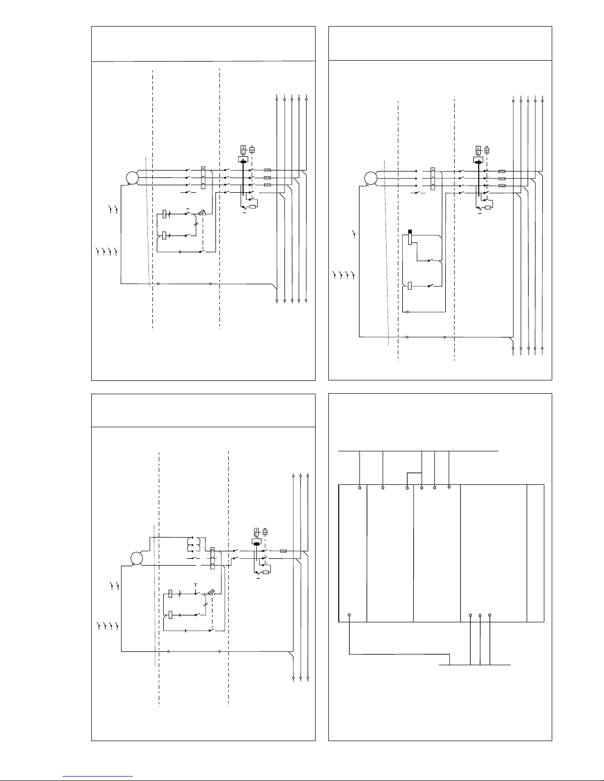
Wiring diagramm for JETSTREAM EuroJet, BAMBO2, BAMBO, COCO
(versions without illumination), JUNO, LIBRA 3-5, LIDO, LIDO 2, VIVA
with pneumatic switch 3N ~ PE 400 V
Wiring diagramm for JETSTREAM, EuroJet, BAMBO2, BAMBO, COCO
(versions without illumination), JUNO, LIBRA 3-5, LIDO, LIDO 2,
VIVA with pneumatic switch and time relay 3N ~ PE 400 V
Wiring diagramm for JETSTREAM, EuroJet, BAMBO2, BAMBO,
COCO (versions without illumination), JUNO, LIBRA 3-5, LIDO, LIDO
2, VIVA with pneumatic switch and token box 3N ~ PE 400 V
Pump control panel build
PE
M1
3~
M
K1
42146
BN
A2 A2
BU
N
N
1
2
1
3
S1
2 2.3
4 2.4
6 2.4
14 2.4
1- 1-
3-
5-
13-
2 2.5
PE
PE
L1
L2
L3
N
PE
L1
L2
L3
N
PE
4A
30mA
F1
16A
53
4
1
531
26
4
2
6
5317
4
2
86
F2
S1
531
426
531
13
F3
1
2
F4
RD
RD
K2
A1
K2
213
A1
1- 2 .5
4x2,5mmý
K1
PE
M1
3~
M
K1
3.5
42146
2-60 min.
A2
A2
A1
N
1
18
S2
2 3.2
4 3.3
6 3.3
14 3.3
15 1-
3-
5-
13-
18 3.5
PE
PE
L1
L2L3N
PE
L1
L2
L3
N
PE
30mA
F1
16A
53
4
1
5
3
1
26
426
5317
4286
F2
S1
531
426
531
13
F3
3
RD
K1
A1
K2
B1
2
1
3
15
K2
3.4
4x2,5mmý
control panel
2.3
4.3
6.3
14.4
1- 1-
3-
5-
13-
2.5
30mA
42
F2
PE
M1
~
M
K1
4
2
14
6
BN
A2 A2
A1
BU
N
N
1
2
1
3
S1
4x2,5mmý
PE
PE
L1NPE
L1
N
PE
4A
F1
16A
1
31
2
42
S1
531
426
531
13
F3
1
2
F4
RD
RD
K2
A1
K2
K1
2
1
1- 2.5
31
cut the general electric connection
before opening the electric control box.
N
1
3 5 1 3 5 13 A1
PE N
L1
L2 L3
246642N14A2
Electric cable 380 V 3N~PE
Ground
Circuit breaker
Circuit
breaker
diving
Main
contactor
Remote control
Towards engine
Pump build
Pump control panel build
pneumatic
switch
pneumatic
switch
pneumatic
switch
 Loading...