

Page 1
USER MANUAL
MODEL#: J2000-BLK
ELECTRIC MOUNTAIN BIKE
Page 2
• Electric Mountain Bike
• Lithium Ion Battery Set
• Pedals
• Charger
• Manual
IN THE BOX
Congratulations on purchasing your brand new Jetson® Electric Mountain
Bike. The Jetson® Electric Mountain Bike is stylish and reliable, and with a
long range of 30-40 miles per charge it can take you anywhere you want to go.
Use it for your daily commute and still have enough juice for those fun leisure
rides. Charging only takes 4 to 5 hours for a full recharge, so you’re ready to
go in no time. With front and back breaks, and an LCD Digital Display loaded
with features, you know you’ll be safe riding at all times of the day. Please
cycle safe, follow your local laws, and take it for a ride!
Before taking the Electric Mountain Bike for a ride, please get adjusted to its
speed, turning radius, and sensitivity to avoid any injury.
SPECIFICATIONS
• Range: Up to 40 Miles Per Charge
• Weight Limit: 265 Lbs
• Braking System: Front + Rear Disc Brake
(Brake for Each)
• Motor: 500 Watt Brushless Electric Motor
• Charge Time: 4-5 Hours Fully Charged
• Battery: Lithium-Ion 36V 10Ah
• Weight: 65 Lbs
SAFETY FEATURES
• Front and Rear Disc Brakes
• Hydraulic Brake Lever
• Easy Grip Handlebars
• Energy-Saving Auto-Shutdown
FEATURES
• LCD Digital Display with Speed,
Odometer and Battery Life
• Motor Assistance While Riding
• Built-in Kickstand
• Shimano 7-Speed Gear
Page 3

Jetson
®
Electric Bike Specifications ...........….………………….....…………….………3
Warnings & General Information ......................................................................4-5
For Your Safety .........................................................................................4
About Your Electric Bike ..........................................................................5
Assembling the Electric Bike ..………......................………..……..........………...…6-7
Front Wheel ..............................................................................................6
Steering Handle .......................................................................................6
Assembly Requirements .........................................................................7
Operation and Adjustment ……………………………………….......…………………...8-14
Speed Boosting System ...........................................................................8
Charging the Battery ...............................................................................8
Display Adjustments ................................................................................9
Parameter Settings ..................................................................................9
Vertical Handle Stem Position ..............................................................10
Seat Position ..........................................................................................10
Understanding the Brake System .........................................................11
Brake Handles ........................................................................................11
Disc Brakes .............................................................................................12
Brake Cable ............................................................................................12
Speed Control System ...........................................................................13
Derailleur ................................................................................................13
Bike Chain ...............................................................................................14
Damping System ....................................................................................14
Care and Maintenance ...……………....……...…..…...............................……….15-17
Routine Inspection Before Use .............................................................15
Battery Care and Maintenance .............................................................15
Charger Care and Maintenance ............................................................16
Everyday Use and Inspection ................................................................16
Regular Cleaning ....................................................................................17
Regular Maintenance ............................................................................17
Riding Techniques ..……………………………………………………………………….....…18
Troubleshooting .....……………………………………………….….…..…….................…19
Limited 1 Year Warranty ......................................................................................20
Product Registration …....……………...….…………………………......…....................21
1
Table of Contents:
Page 4
2
Page 5
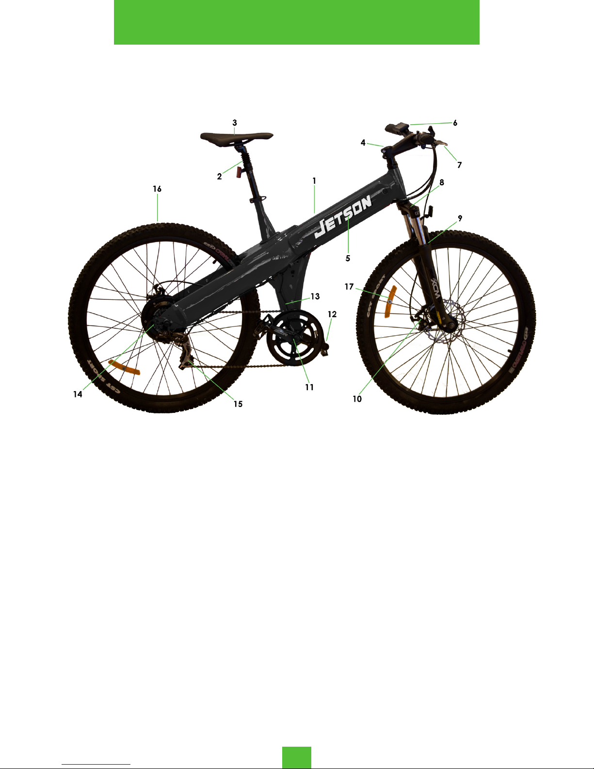
1. Frame
2. Seat Post
3. Saddle
4. Vertical Handle Stem
5. Battery
6. LCD
7. Brake Lever
8. Damping Coefcient
9. Front Fork
10. Disc Brake
11. Crank
12. Pedal
13. Speed Sensor
14. Motor
15. Rear Derailleur
16. Rim and Tire
17. Reector
3
SPECIFICATIONS
Page 6

FOR YOUR SAFETY...
The Jetson® Electric Mountain Bike is designed to hold a maximum load of 265 pounds, and run for between 30 and 40 miles
per charge (depending on road conditions and driving factors).
For your continued safety, we recommend taking the following
precautions:
• Do not operate this electric bike without carefully
reading the manual and understanding its controls.
• Always wear a helmet, gloves, and other protective
gear before riding to protect yourself in case of an
accident.
• Observe all traffic rules and regulations when using
this electric bike.
• Do not carry passengers.
• When riding in rainy, snowy, or slippery conditions,
reduce your speed and increase the distance
between yourself and other vehicles.
• Only use this electric bike in ambient temperatures
between 14 and 104 degrees Fahrenheit.
• The maximum weight capacity of the bike is 265
pounds.
• Certain high-intensity conditions (such as frequent
braking and starting, uphill riding, muddy roads, and
the like) will drain the battery quickly, affecting the
mileage per charge. We recommend you avoid the
above factors when riding.
• If the storage battery is not used for more than a
month, charge the electric bike for a full cycle again
before use.
• Do not allow water to enter the controller or motor
wheel, as it may cause the electrical equipment to
short circuit or be permanently damaged.
• Do not allow anyone to manipulate or modify the
electric bike. This immediately voids the warranty.
• Do not throw away the batteries. Always recycle
batteries at a proper recycling location.
4
WARNINGS & GENERAL INFORMATION
Page 7

ABOUT YOUR ELECTRIC BIKE...
The Jetson® Electric Mountain Bike has many special functions
and uses that help bring your riding experience to the next level.
Please be sure the cyclists using the electric bike know the required driving techniques before taking the electric bike on the
road. For your convenience and security, pay attention to the
following:
• In the process of regular use, pay attention to the
fastening status of the motor and rear fork. If you
notice it begins to loosen, tighten it before use.
• When starting the power supply or beginning to
ascend a steep slope, use the pedals for as far as
possible to reduce the starting current and extend
the battery life.
• In rainy conditions, pay attention to when the water
depth is more than the center point of the wheel.
These conditions make it more likely for the motor to
become soaked in water, resulting in electrical failure.
• Always use the provided charger to charge the
electric bike.
• Do not cover the battery box or charger. Always
allow proper ventilation when charging and using the
electric bike.
• Maintain proper air pressure in the tires. This helps
prevent increased resistance when driving, minimizes
the wear on the tires, and reduces the risk of
damaging the rims.
• When going downhill or riding at high speeds, do not
use the front brakes. This avoids sudden changes in
the center of gravity and reduces the danger of
accidents.
5
WARNINGS & GENERAL INFORMATION
Page 8
Installation of the Front Wheel
1. Take out the front wheel, and loosen
the nut and hook on the front wheel axis.
2. Make sure the disc plate is inserted into
the disc brake notch. Place the front
wheel axis into the front fork contact pin,
as seen in the image to the right.
3. Place the washer on first, then tighten
the nut with a 15mm opening wrench.
NOTE: When fastening the nut, press down on the front fork so that the front wheel
axis can line up tightly with the front fork.
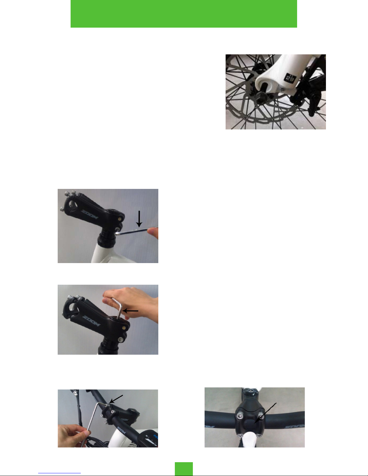
Installation of the Steering Handle
1. Take out the handle bar, and remove
the protective paper from above the
handle bar and stem.
2. Place the stem on the front of the
bike frame, and line it up with the front
wheel.
3. Tighten the stem with the 5mm hexagonal spanner, as pictured in Step 1.
4. Tighten the stem with the 6mm hexagonal spanner, as pictured in Step 2.
5. Place the handle bar in the stem and
tighten the four bolts with the 5mm hexagonal spanner, as pictured in Step 3.
6. Ensure that the thread position on the
handle bar is in the middle of the stem,
as pictured in Step 4. Tighten all bolts on
the stem and handle to lock all pieces
into place.
STEP 1
STEP 2
STEP 3 STEP 4
6
ASSEMBLING THE ELECTRIC BIKE
Page 9

Assembly Requirements
In order to ensure safety and continued performance, tighten all
fastenings to the following torque specifications:
1. Front Wheel Nut: no less than 18N.m
2. Rear Motor Nut: 35 to 45N.m
3. Middle Axis Component Lock: no less than 50N.m
4. Core Screw Rod (in the Vertical Handle Stem): 15 to 18N.m
5. Across/Vertical Handle Stems: 15 to 18N.m
6. Saddle Pipe Ring: 6 to 8N.m
7. Saddle and Seat Post Ring: 15 to 18N.m
8. Brake Handle: no less than 10 to 12N.m
9. Derailleur: 8 to 10N.m
7
ASSEMBLING THE ELECTRIC BIKE
Page 10

8
Speed Boosting System
The Speed Boosting System (also known
as the 1:1 Boosting System) assists with
manual operation of the electric bike.
When pedaling, it will automatically
sense your riding speed and assist
accordingly, to make your ride easier.
The boosting system is comprised of three parts: a Controller, a
Sensor, and an Induced Cartridge.
Charging the Battery
Charge the battery before your first use. To obtain a full charge,
it is recommended that you charge the battery for 6 to 8 hours.
After your first charge, use the electric bike until the battery is
fully drained. Then, charge the battery again for 8 to 9 hours. This
cycle will help activate the battery, and ensure the longevity of
the battery’s life.
Only use the included charger with this battery. The use of chargers not designed for the electric bike will void the warranty.
Using other chargers may do permanent damage to the battery,
and could lead to unexpected dangers.
To charge the battery:
1. Check that the voltage of your power source matches the
rated input voltage of the charger.
2. Connect the output plug of the charger with the charging
jack of the battery. Connect the plug into an AC power supply.
3. Check that the power indicator light and the charge indicator lights are on. This shows that the battery is charging properly.
When the light turns green, the battery is sufficiently charged.
4. After the battery is fully charged, unplug the cable from both
the AC power supply and the battery.
NOTE: The battery should be charged away from high temperature, high humidity, and fire. Do not overcharge the battery, as that will reduce its longevity. Once
the battery is fully charged, unplug it as soon as possible to avoid overcharging.
OPERATION AND ADJUSTMENT
Page 11

Display Adjustments
MODEL: 861-A | Operating Voltage: DC36V
To increase the Assistance Level, press
To decrease the Assistance Level, press
To switch between speed display modes, press and hold
To set/release cruise control, press and hold
To turn the LCD screen on/off, press and hold
To switch between the different displays, press
The LCD Display helps you control many features on your electric bike, including adjusting the Assistance Level (the amount
of motor assistance during normal riding), tracking your speed
and distance, and setting the cruise control on your bike.
Parameter Settings
Press and hold and to enter the Parameters menu,
where you can adjust the following settings:
P01: Rim Size in inches (5-50)
P02: Unit of Magnet Numbers (1-100)
P03: LCD Brightness (1 [dark] - 3 [bright])
P04: Distance Setting (0 [KM] - 1 [MILE])
P05: Battery Voltage (24V - 36V)
P06: Sleep Timer (0-60 minutes)
P07: PAS Setting (power assistance, 20.0-60.0)
P08: Drive Mode (0 [PAS Drive], 1 [Electric
Drive], 2 [PAS and Electric Drive])
Press or to adjust the value. Press to save the current value. Press to go to the next Parameter. Once you
are finished setting the Parameters, press and hold and
to exit the Parameters menu.
9
OPERATION AND ADJUSTMENT
Page 12

10
Vertical Handle Stem Position
The position and adjustment of the Vertical Handle Stem is very
important, as it allows for full mobility with the steering system.
Make sure that the distance of “G” in the figure above is under
5mm. The upper part of the fork-stem where the stem extension is
clamped should not be threaded.
Seat Position
The seat post has a safety line (known as the Max Line), and
when inserted it should not be visible above the seat connector.
Any position higher than this may cause serious injury to the rider.
To adjust the seat to the proper height, set a pedal to the lowest position and sit on the seat. When you press your heel flat
onto the pedal, your leg should be slightly stretched but not fully
extended. If you cannot touch the pedal without using your toes,
or if you cannot stretch your leg when the pedal is at its lowest
position, the seat needs to be adjusted. The wrong seat height
can lead to possible fatigue and injuries. Move the quick release
handle on the seat post to OPEN, adjust the seat, and then close
the quick release handle to set the position
Set the seat angle with the front end slightly upward. This helps
to avoid leaning forward when riding. The front and rear of the
seat can be appropriately adjusted based on individual height.
Generally, the seat bar is set in the middle.
1. Stem Extension
2. Extended Fork-Stem
3. Spacer Rings
4. Bearing Assembly
5. Head Tube
6. Stem Extension to Stem Clamp
OPERATION AND ADJUSTMENT
Page 13

Understanding the Brake System
The brake system is a necessary part of any bike, and is key to
the overall safety of the rider. Before using this electric bike, you
must understand the brake system, and feel confident when
inspecting it and doing any adjustments that are necessary.
A common misconception about brakes is that when you press
hard on the brakes, the bike will stop in a short distance. However, it’s important to understand that when you press hard on
the brakes, the wheels become suddenly jammed by the brake
rubber, and the bike glides horizontally, wearing down the tires
and the brake pads. This is not only dangerous, but it also lengthens the distance needed to reach a full stop. It’s important to
think about the brakes as a way to adjust the speed of the bike
gradually, rather than a way to bring the bike to an immediate
halt.
The brake system is comprised of the Brake Handles, the Disc
Brake, and the Brake Cable.
NOTE: Make sure the distance between the Brake Shoe Block and the Rim is
the appropriate size. Adjust according to the instructions detailed on the next
page. If the Brake Shoe Block or Brake Cable become worn or damaged, please
replace before using the electric bike again. When riding in rainy conditions, the
function of the brakes will be weakened, so please reduce your overall speed
and allow for a longer braking distance.
Brake Handles
The structure of the Brake Handles is as
shown in the image on the left. The right
brake handle controls the front brake, and
the left brake handle controls the rear
brake. The adjusting screw is used to adjust
the distance between the brake shoe
block and the rim.
The best placement of the brake cable is about half the distance between the brake handle and the grip of the Across
Handle Stem. If the brake is tight when the Brake handle is approaching the grip of the Stem, then the distance between the
brake show block and the rim is too large and must be adjusted.
11
OPERATION AND ADJUSTMENT
Page 14

Disc Brake
To adjust the brake shoe block:
1. Loosen the position adjustment bolt.
2. Use the left and right knobs to adjust the distance of the shoe
block. The left knob increases the distance of the brake shoe
block, and the right knob decreases it. This adjusts the braking
abilities of the electric bike.
NOTE: Do not oil the surface of the Brake Disc, this may lead to serious braking
problems.
1. Stoke Adjusting Bolt
2. Position Adjusting Bolt
3. Rocker Arm
4. Permanent Seat
5. Brake Shoe Block
6. Shoe Block Adjusting Bolt
7. Permanent Seat of Brake Line
Brake Cable
• The brake cable should be arranged in as straight a
line as possible. Please avoid any turns or curves in
the cable, as that will affect braking capabilities.
• To avoid splitting of the cable, make sure that the tail
sleeve fully covers the line end.
• Take the brake cable out regularly to oil it, this helps
avoid resistance from rust build-up.
• The length of the brake cable is meant to allow the
cable to remain unstuck when the handlebar turns
sharply left or right. Please test that the cable does
not get tangled by testing the turning of the handle
bar before operating the electric bike on the road.
12
OPERATION AND ADJUSTMENT
Page 15

Speed Control System
The Speed Control System is made to help you travel through
various terrains and conditions easily by adjusting based on the
strength of your pedaling.
The Speed Control System is comprised of a Derailleur, a Front
and Back Fender, a Chain Plate, a Flywheel, and Shift Cables.
NOTE: Do not backpedal when shifting gears, this could potentially lead to the
a failure of shifting and the chain falling off. Do not change gears substantially,
always shift gradually and in accordance with the speed at which you are currently travelling. Shifting up or down multiple gears at once will lead to more
rapid wear and tear of the Speed Control System. The chain, fluted disc, flywheel,
and Derailleur should always be washed, wiped, and oiled appropriately.
Derailleur
The Derailleur is a 7 speed dial type, positioned on the right side of the handlebar.
When the large trigger is pushed, the gear
shifts to a lower gear, while the button
at the bottom of the Derailleur shifts to a
higher gear. Lower gears are preferable
when riding up inclines, while higher gears
are great for downhill speeds.
The Derailleur is attached to the Back
Fender. When the shift cables are too loose
or too tight, or if the speed controller does
not work properly, the H and L Bolts need
to be adjusted.
To adjust the H Bolt to its proper position,
adjust the chain so that it’s on the smallest
flywheel, then turn the H screw so that the
guide pulley with the smallest gear is on
a straight line. To adjust the L Bolt, set the
chain to the largest flywheel, then turn the
L screw so that the guide pulley with the
largest gear is on a straight line (as shown
in Figure 1).
FIGURE 1
13
OPERATION AND ADJUSTMENT
Page 16

Bike Chain
The chain must maintain a slight sag to be able to switch between gears when shifting. It is important to make sure that the
chain is the proper length, or the cycling performance will be
affected negatively.
To determine the length of the chain,
adjust the Back Fender to the lowest
gear, the chain should sag 15mm or less
(as shown to the right). If the chain sags
more than 15mm, the chain is too long
and must be shortened by the supplier to
maintain the best cycling performance
for your electric bike.
Damping System
The Damping system helps keep the tire buffer in contact with
the ground when the electric bike is running on uneven road.
This helps you feel more comfortable during difficult conditions.
Damping hardness can be adjusted by
rotating the Damping Coefficient (as seen
on the left), according to road conditions
and personal preference. The Damping system can be found on the Front Fork, please
check Page 3 to locate it on the electric
bike.
NOTE: Do not adjust damping while in motion. Be sure to test damping levels fully
to match your preferences.
To adjust the damping, rotate towards the + sign to increase
the damping hardness. Rotate towards the - sign to reduce the
damping hardness.
14
OPERATION AND ADJUSTMENT
Page 17

15
Routine Inspection Before Use
Regular maintenance and inspection helps lengthen the lifespan
of your electric bike. Before riding, it is important to check the
following:
• Make sure the battery box is secured in the slot of the
battery box.
• Turn on the LCD Screen and check that all electrical
functions are behaving normally.
• Make sure the braking power-off function and the
brakes themselves are in good condition.
NOTE: Do not perform any maintenance that involves removing parts or components. As with all mechanical components, this electric bike will endure wear
and high stress. These components will react to wear and stress in different ways,
so it is important to regularly check and, if necessary, replace worn-down parts.
Battery Care and Maintenance
• Keep the battery out of extreme temperatures.
• Operating temperature when charging: 32° - 113° F.
• Operating temperature when discharging: -4° - 113° F.
• Do not short circuit the discharge/charge terminals of
the battery.
• Do not leave the battery charging overnight, or for
long periods of time.
• To avoid damage to the battery, do not subject it to
intense physical shock, severe vibration, or strong
impacts.
• Do not expose the battery to water or other moisture.
Protect the discharge/charge terminals from rain or
water logging.
• Keep the battery away from children.
• When the battery is not in use for an extended period
of time, remove the battery and store it safely.
• Do not disassemble the battery.
• If you have any questions about this battery or its
usage, contact the Customer Service department.
CARE AND MAINTENANCE
Page 18

Charger Care and Maintenance
• Prior to your first ride, charge the battery fully as
described earlier in this manual.
• Make sure the charger is at least 3 feet away from
computers, televisions, refrigerators, washing
machines, and other electric devices while charging.
• Only use the charger indoors, and make sure the
conditions are dry and below 113° F.
• Only use the charger supplied in the box, and do not
charge other types of batteries with this charger.
• If any strange smells appear while charging, unplug
the charger immediately and contact Customer
Service.
• Do not use this charger in dusty or damp places.
• Always plug the charger into the wall outlet prior to
plugging it into the battery.
• When the charging is complete, first unplug the
charger from the wall outlet, then unplug it from the
battery.
• Do not let children play with the charger.
• Do not disassemble the charger.
• Do not put any liquid or metal into the charger.
• Do not put anything on top of the charger, and
always keep it in a well-ventilated area when the
charger is plugged in.
• Do not disconnect the battery while charging.
• Do not use the electric bike or any of its functions
(such as the motor or LCD Screen) while the battery is
charging.
Everyday Use and Inspection
In everyday use of the electric bike, a number of mechanical
and electrical parts will be worn down, and screws or other
fasteners may also become loose. Either of these situations could
potentially cause the electrical appliances to cease functioning.
It is important to check your electric bike before every ride for
irregularities, because these problems could lead to mechanical
failures and dangerous riding situations. It is your responsibility to
address the issues as soon as possible.
16
CARE AND MAINTENANCE
Page 19

Regular Cleaning
• Remove the battery box from the electric bike before
cleaning.
• Do not use water to clean the electric bike.
• Delicately wipe any painted or plastic parts with a
soft cloth and a neutral cleaning solution. Carefully
dry the parts with a soft, dry cloth to finish.
• Clean the battery contacts with a damp cloth of
neutral cleaning solution.
• Do not use grease or a greasy cloth when wiping
down the electrical connectors, brake pads, wheels,
tires, or plastic parts.
Regular Maintenance
Every 1 to 2 months, it is recommended that you check the following:
• Check that the handlebar and saddle post are correctly
inserted and tightened.
• Check that the wheel hub mounting nuts are correctly
tightened.
• Check that the wheel rims are not cracked and that no
spokes are loose or broken.
• Check that the tires are not worn or cut.
• Check that the tires are correctly inflated.
• Check that the battery contacts on the frame are not
dirty or oxidized.
• Check that the batteries are sufficiently charged.
• Check that the front and rear brakes are working
correctly.
• Check that the cables are sufficiently greased, and that
the brake pads are in good condition.
• Check that the frame welds are in good condition, and
are free of corrosion or oxidation.
17
CARE AND MAINTENANCE
Page 20

A proper cycling posture is important to your safety while operating the electric bike. Good posture is based on the height
and size of the cyclist, so it’s important to adjust the electric bike
when changing cyclists. To adjust the bike to fit your needs, follow these three steps:
1. Adjust the position of the seat: Push the pedal down to the
lowest point, and press on it with your heel. Adjust the seat
height so that your legs can extend comfortably but are not
overextended.
2. Adjust the front and rear position: Push the pedal to a 45°
angle, then adjust the seat forwards or backwards so that your
legs can comfortably reach the pedals.
3. Adjust the height of the handlebar: The upwarping type of
handlebar is typically 30 to 50mm higher than the seat, while the
flat type of handlebar is the same height as the seat.
NOTE: After adjusting, make sure that the seat and handlebar are tightened into
place.
Sitting Posture
The cyclist’s weight should be evenly distributed between the
handlebar and the pedals. This helps prevent hip pain while using the electric bike.
Proper Pedaling
The proper position for pedaling is the middle of the foot is the
middle of the pedal. Feet should be parallel to the center of
the bike while pedaling. If the feet are too open or narrow, it will
diminish the efficiency of the pedaling and could cause pain or
physical stress.
When to Change Gears
The gears on your electric bike are meant to assist in times of
uneven pedaling. So, the speed change is intended to be more
labor-saving and comfortable. Some examples of good times
to shift gears are: climbing uphill terrains, uneven road surfaces,
against strong winds, and when the cyclist is feeling tired.
Braking
Always maintain a safe distance when riding, as braking is
meant to be a gradual process. Using both brakes at once will
produce a quicker stop, but also creates the risk of throwing the
rider off the bike. The best method is intermittent braking, which
achieves an eventual stop without drastic changes of speed.
18
RIDING TECHNIQUES
Page 21

Issue Potential Cause Solutions
Failed speed
change, or very
low velocity.
• Low Battery Voltage.
• Bad governor handle.
• Bad controller.
• Charge the battery.
• Replace the governor
handle or controller.
Motor does not
work when the
power is turned
on.
• Bad governor handle.
• Bad electric door lock
and contact point.
• Bad controller.
• Replace the governor
handle or controller.
• Re-weld the contact
part.
Inadequate
mileage from
charge.
• Tires have low air pressure.
• Inadequate charging or
charger failing.
• Damaged or expired battery.
• Frequent breaking and
restarting.
• Pump the tires to
proper pressure.
• Recharge the battery.
• Replace the battery
or charger.
The charger no
longer works with
the battery.
• Charger wiring is loose or
damaged.
• The battery weld line is
damaged or fell off.
• Weld the connecting
line, or replace it.
The booster has
no power assist.
• The induced cartridge
has poor contact or is
damaged.
• The booster wiring is bad
or damaged.
• Adjust the induced
cartridge or replace
it.
• Reconnect the booster or replace it.
19
TROUBLESHOOTING
Page 22

TO QUALIFY FOR WARRANTY SERVICE:
1. You must present a copy of the sales receipt from an approved retail partner
within 90 days of purchase.
2. This product can not be used for rental or commercial use.
3. This product can not be used for competition.
LIMITATIONS OF LIABILITY
• This Limited 1 Year Warranty is non-transferable after the Product’s initial sale.
• No unapproved modifications can be made to the Product, its performance or
otherwise, in order for this Limited 1 Year Warranty to remain in effect.
• No reimbursement is provided for towing, loss of time, loss of use, inconvenience,
incidental or consequential damages.
• Warranty is void if weather related water damage is determined. Owner is
responsible for storage and protection from weather.
• Jetson® makes no warranty with respect to products or trade accessories not
made by Jetson®, including, but not limited to, motors, tires, wheels and batteries,
such products or trade accessories, such items being subject to the original
manufacturer’s warranty, if any.
• This Limited 1 Year Warranty does not cover minor surface blemishes, rips, tears,
or other cosmetic damages due to normal use, or other intentional or unintentional
damage to the Product.
• This Limited 1 Year Warranty will not cover any damage which results from the
application of improper cleaners, solvents or chemicals to the Product, water
damage, smoke or soot, or from exposure to salt-water, sea breeze or salt.
• This Limited 1 Year Warranty will not cover any damage which results from aging,
such as fading of paint, deterioration of plated surfaces, deterioration of rubber
or plastics, or rusting.
• This Limited 1 Year Warranty does not cover improper repair or misdiagnosis of
problem.
• This Limited 1 Year Warranty covers only parts and labor due to manufacturer
defect.
• Damage due to misuse or neglect, use other than as specified in the Owner’s
Manual, or use under abnormal conditions are not covered by this Limited 1 Year
Warranty.
OWNER’S WARRANTY RESPONSIBILITIES
As the vehicle owner, you are responsible for the performance of the required
maintenance. You should maintain a record of all maintenance performed your
vehicle and retain all receipts covering maintenance on your vehicle. You may be
denied a warranty claim solely because of your failure to ensure the performance
of all scheduled maintenance or lack of maintenance records or receipts. As the
vehicle owner, you should be aware that you may be denied your warranty coverage
if your vehicle or a part has failed due to abuse, neglect, improper maintenance, or
unapproved modifications. For any issue regarding your Jetson® product, call toll
free 1-(888) 976-9904.
20
LIMITED 1 YEAR WARRANTY
Page 23

Please complete and mail this card within 10 days of purchase.
Name: _____________________________________________________________________
Age: _______________________________________________________________________
Address: ___________________________________________________________________
City, State, Zip: _____________________________________________________________
Email: _____________________________________________________________________
Home Phone: __________________ Work Phone: ________________________________
Purchase Date: ___________ Purchased from: _________________________________
Serial Number: _____________________________________________________________
Product: ___________________________________________________________________
Gender: _______________ Occupation: ________________________________________
Is this your first Jetson product? _____________________________________________
Other similar product owned before: _________________________________________
How did you hear about the Jetson® Electric Mountain Bike?
____________________________________________________________________________
____________________________________________________________________________
Complete this form and mail it to:
Attention: Product Registration
Jetson Electric Bikes
1 Rewe Street
Brooklyn, NY 11211
21
PRODUCT REGISTRATION
Page 24

A LEADER
IN ELECTRIC MOBILITY
888-976-9904
WWW.JETSONBIKE.COM
 Loading...