

JET OPTOELECTRONICS 30101ABOX00 User Manual
3010-1A User’s manual
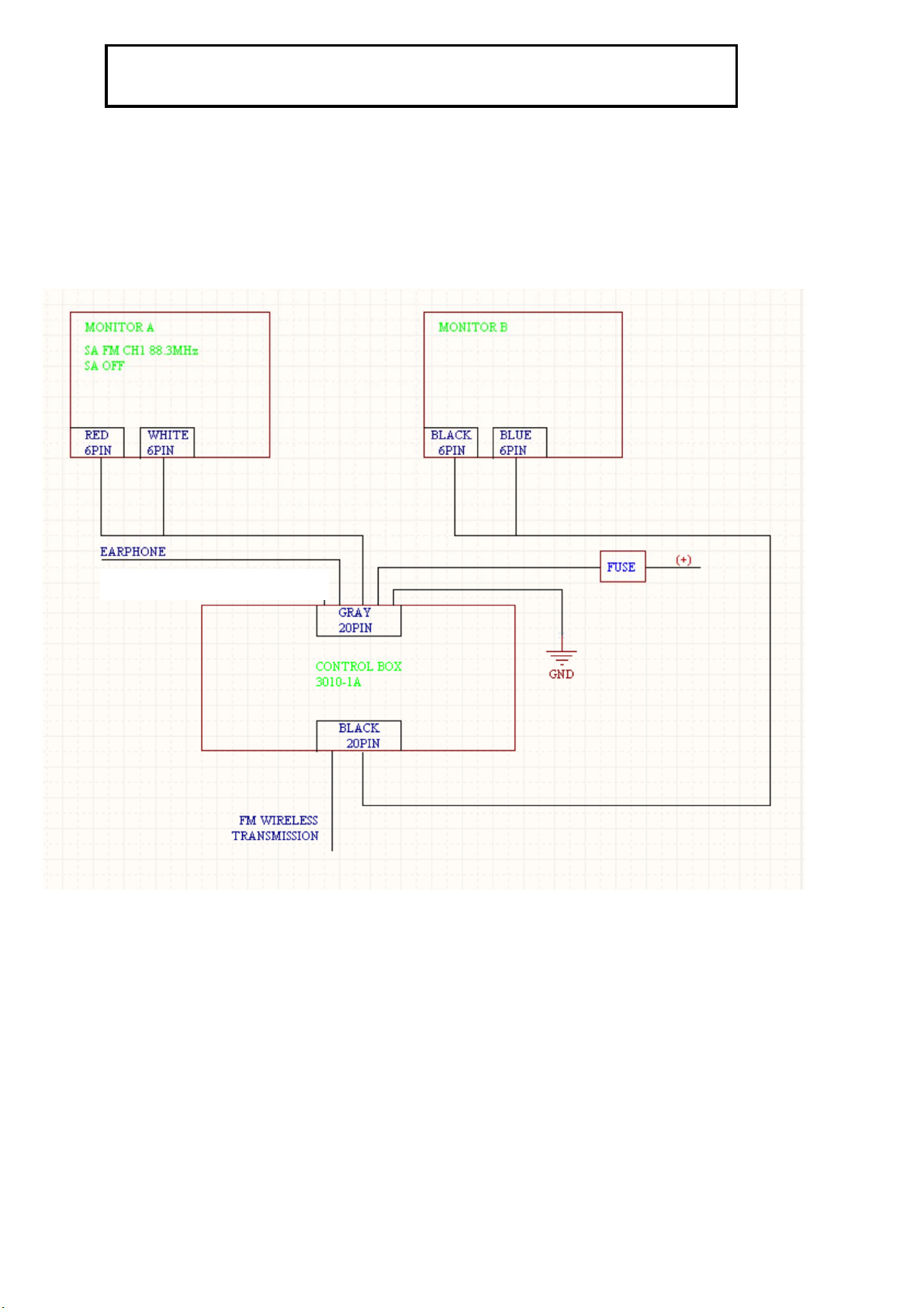
一、 Wiring :Power Supply 12~16 DCV
MODULE Connection instructional diagram
1 This product is car audio and video control box
2 Recommendations Please installation by professional technicians
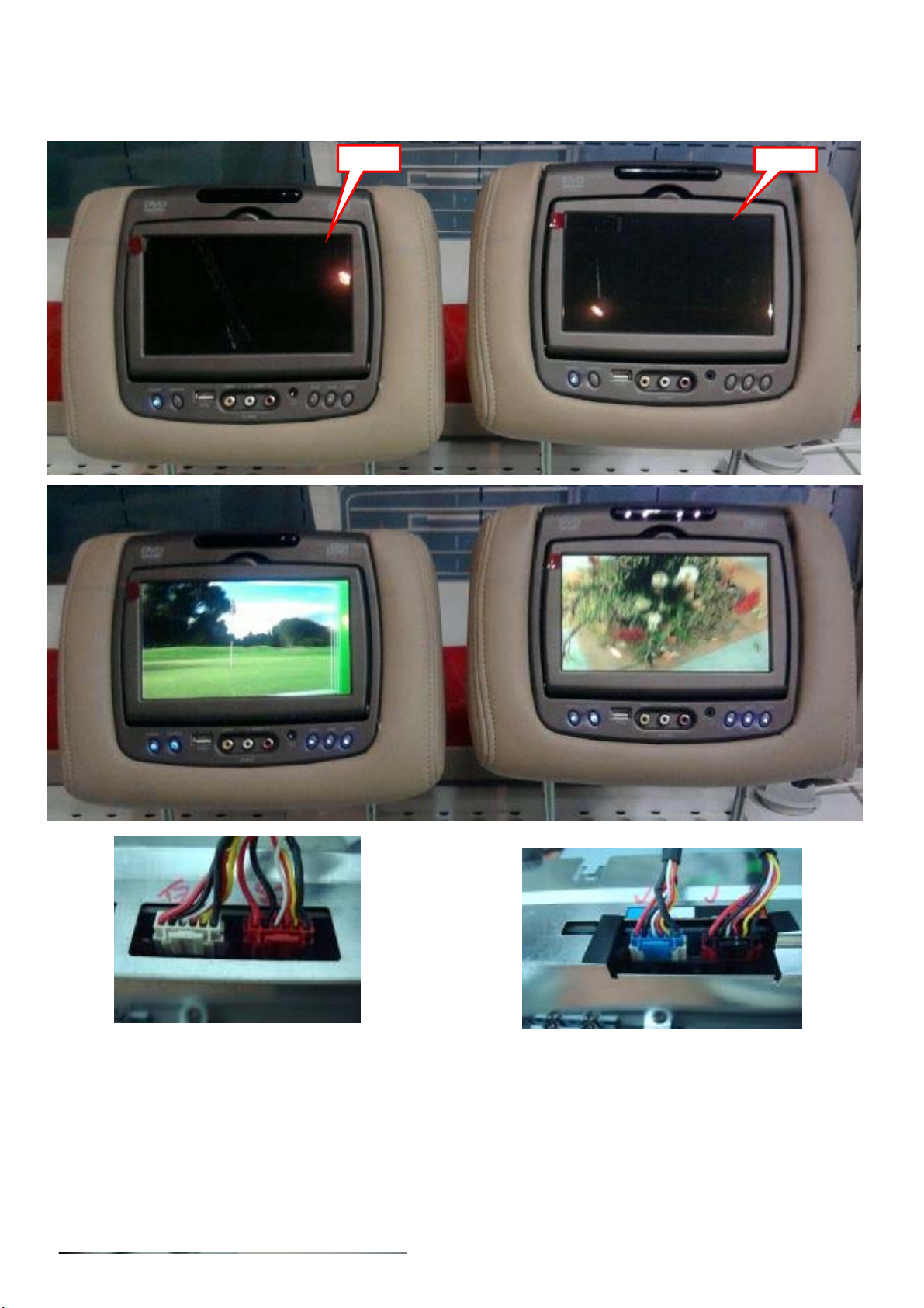
3 Will pick a good line monitor A and monitor B、
each placed within the head restraint is being co-pilot。
4 Will take a good line Ccontrol Box,
Placed in the bottom of the co-pilot seat chairs。
1
二、Explanation & Specification:
Monitor A
Monitor B
Monitor A Monitor B
2
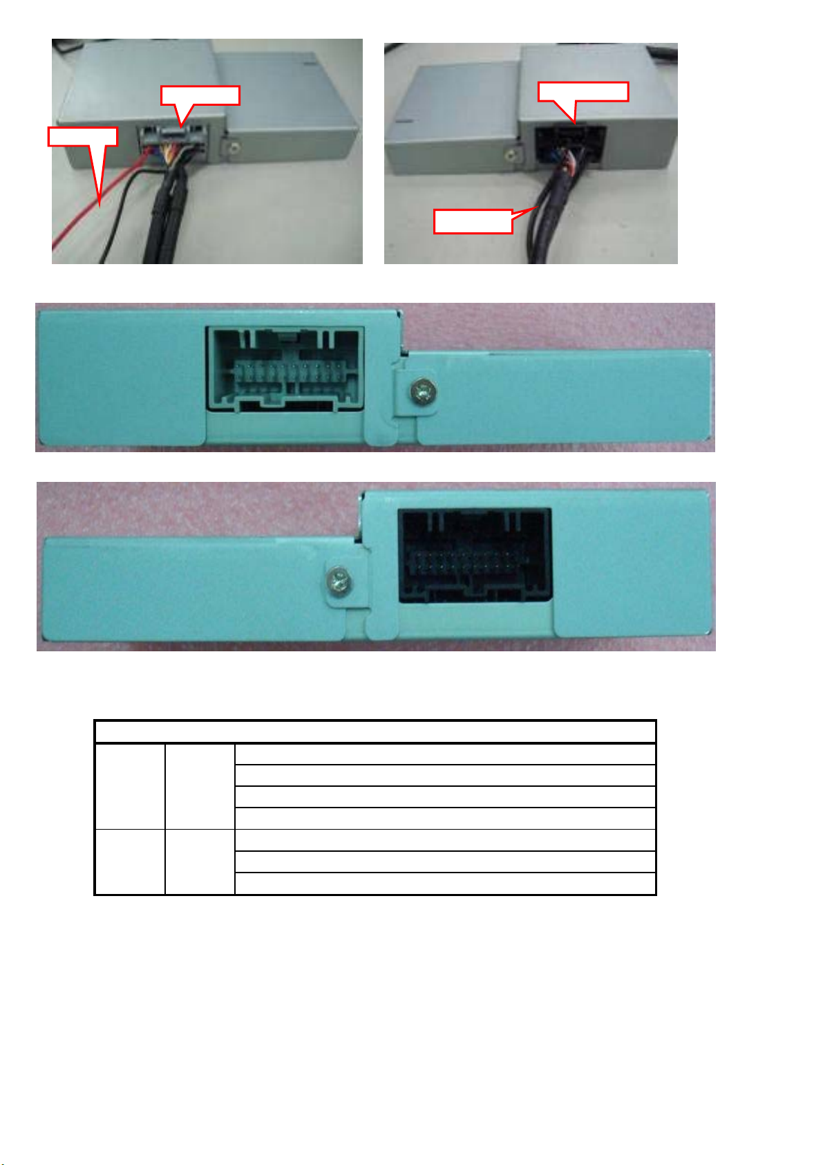
Power Supply
Gray Connector
Black Connector
Black Antenna
WIRE CABLE FUNCTION NAME
To Power supply DCV:12V~16V
1
GRAY
To Monitor A Red Connector Power & AV Output
To Monitor A White Connector AV Input & I2C
To Ear phome Audio Aux Output
To Monitor B Blue Connector AV Input & I2C
2
BLACK
To Monitor B Black Connector Power & AV Output
To FM Antenna Output 88.3 MHz ~107.7 MHz
FM Transmitter frequency : 88.3MHz ~107.7 MHz
FM Modulator IC (Quintic) : SMD QN8007B QFN24
3
 Loading...