

Installation instructions
Jetmaster Mark 4 Gas Log

Jetmaster gas logs are fuel effect appliances intended for
use in a fireplace suitable for the burning of wood. It is
recommended that the Jetmaster gas log be placed in a
properly installed Jetmaster Convector firebox in order
to ensure an adequate draught and greater efficiency.
The Jetmaster open fire is an approved open fire to
burn wood. The following size fireboxes are available
for the Type 1 Burner to be inserted into.The firebox
can be installed into an existing fireplace subject to the
chimney being the appropriate size and in sound
condition. The firebox can also be installed from new
with a gather and a flue.
(DIMENSIONS IN MILLIMETERS)
AA1 B C D E
600 670 700 350 650 200 200
600 LOW 670 700 350 600 200 200
700SH 770 800 350 650 200 200
700SH LOW 770 800 350 600 200 200
700D 770 800 400 700 225 200
600/700 Mark 4 Gas Log Burner. Suitable for model fireboxes 600-700D
IMPORTANT: Installation of this appliance should only be
carried out by an authorised person in accordance with the
manufacturers instructions. All relevant codes and regulations
laid down by the gas supply authorities, uniform building
regulations and the requirements of local municipal authorities
must be observed.
Model Type 1
Decorative Gas Log Fire
600/700 MARK 4 GAS LOG BURNER
DATA PLATE: Refer to date place for information in
respect of gas pressure, consumption and gas type, Natural
or LPG.The data place is located to the side of the grate.
Location Requirements
1. The fireplace construction must be non-combustible
and in accordance with the current Building Regulations
for chimney and fireplace intended for solid fuel use.
2. The flue and/or chimney should be tested and
proven to have an adequate updraft which shall be
sufficient to remove all waste products of combustion.
A minimum cross-sectional area of 40,000 sq mm is
required with a minimum chimney flue height of 3.6
meters.The installer must satisfy himself that the fireplace
is functioning properly and a smoke test is recommended.
When using a Jetmaster firebox the appropriate diameter
flue for the model fireplace should be used.
3. The appliance must comply with AG601 Gas
Installation Code.
4. In cases where a twin walled metal flue is used and
provided such flue shall comply with the clearances
specified in AS2918 or manufacturers instructions in
respect of clearance to combustibles.
5. In cases where a metal is used, such flue shall
comply with the standards relating to grade, quality and
thickness as are current.
6. An approved flue cowl with a minimum cross-sections
of 40,000sq mm shall be affixed to the top of the flue or
chimney.
7. The installer must remove or fix in an open position
any damper which may be affixed to or contained in any
fireplace.
8. It should be noted that the Code AS2286 (space
heating appliances-secondary guards) requires a dress
guard to be affixed to the appliance or fireplace.
9. Ventilation. An opening to outside with a minimum
free ventilation area of 400sq cm shall be provided for
each decorative gas log fire.
NOTE: The chimney in which the appliance is installed
is not to be considered as a ventilation opening.
10. The appliance shall be installed into a fireplace with a
minimum opening of 600mm width and 217mm depth
and shall be no greater than 10650mm width and
400mm depth.
11. Combustible materials to be no closer than
100mm either side of fireplace opening and no closer
than 150mm above the opening. The firebox should
have a non combustible hearth in front of the firebox.
Installation instructions Jetmaster Mark 4 Gas Log
Electricity
Supply
Gas
Supply
Fan
Switch
Installation:
Fitting the Gas Grate
1. Check unit is suitable for intended gas supply.
2. The position of the gas control and inlet is on the
right hand side. A regulator is supplied when fitting to
natural gas. A gas cock must be fitted prior to the
burner to enable the unit to be removed for servicing.
(It is recommended that the fireplace and chimney be
cleaned prior to fitting the gas unit).
3. In an existing fireplace or Jetmaster firebox (if being
used), drill a 15mm hole through the right hand side of
the fireplace (as you face it) at a point of 85mm from
the base and 85mm from the front face.
4. Cut and debur both ends of pipe. Fit the end to
the gas supply point and turn on for approximately
5 seconds to clear the pipe of any dirt or grit. Fit the
other end to the gasunit.
5. The regulator supplied and attached to the
appliance is for natural gas.
6. Turn on the gas and check all connections for leaks
using soapy water for approved method. Fix any leaks.
7. This appliance is approved for use only on Natural
Gas and must not be converted to any other gas.
Adjusting Pressure, Pilot
and Low Fire
1. All settings are set to operate at appropriate
pressures (see data plate).Test point is located on gas
valve.
2. Check low fire if adjusted correctly.
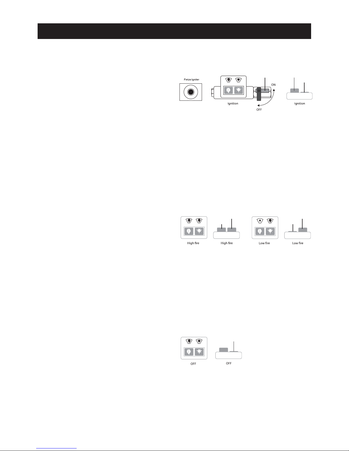
Lighting Instructions
PILOT IGNITION
1. To turn burner on stop cock needs to be in
horizontal position.
(FIGURE 1)
2. Ensure left hand button on control is fully extended
before igniting
(FIGURE 2) (a large flame should be showing
in the window).
3. Depress right hand button
(FIGURE 3) (which is the
pilot) in and hold whilst either lighting manually with
lighted match or depressing piezo. Lighter needs to be
placed at pilot until burning. Hold button in for
approximately 20 seconds then release. If pilot goes
out repeat step 3.
BURNER IGNITION
1. The button on the right
(FIGURE 4) controls the gas to
the burner and the button on the left
(FIGURE 5) controls
either high or low settings.
2. With pilot only burning right hand button will be
fully depressed. Push right hand button in and release
button to a fully extended position and main burner
will ignite.
3. Depress left hand button
(FIGURE 6) for low setting.
Small flame will appear in left hand window.
TURNING MAIN BURNER OFF
1. Depress right hand button
(FIGURE 7) in from fully
extended position to off position.
TURNING PILOT TO OFF POSITION
1. Turn stop cock from horizontal to vertical
(FIGURE 1)
to turn pilot off.
Installation instructions Jetmaster Mark 4 Gas Log
(FIGURE 1) (FIGURE 2)
(FIGURE 3)
(FIGURE 4)
(FIGURE 5)
(FIGURE 6)
(FIGURE 4)
(FIGURE 7)
Installation instructions Jetmaster Mark 4 Gas Log
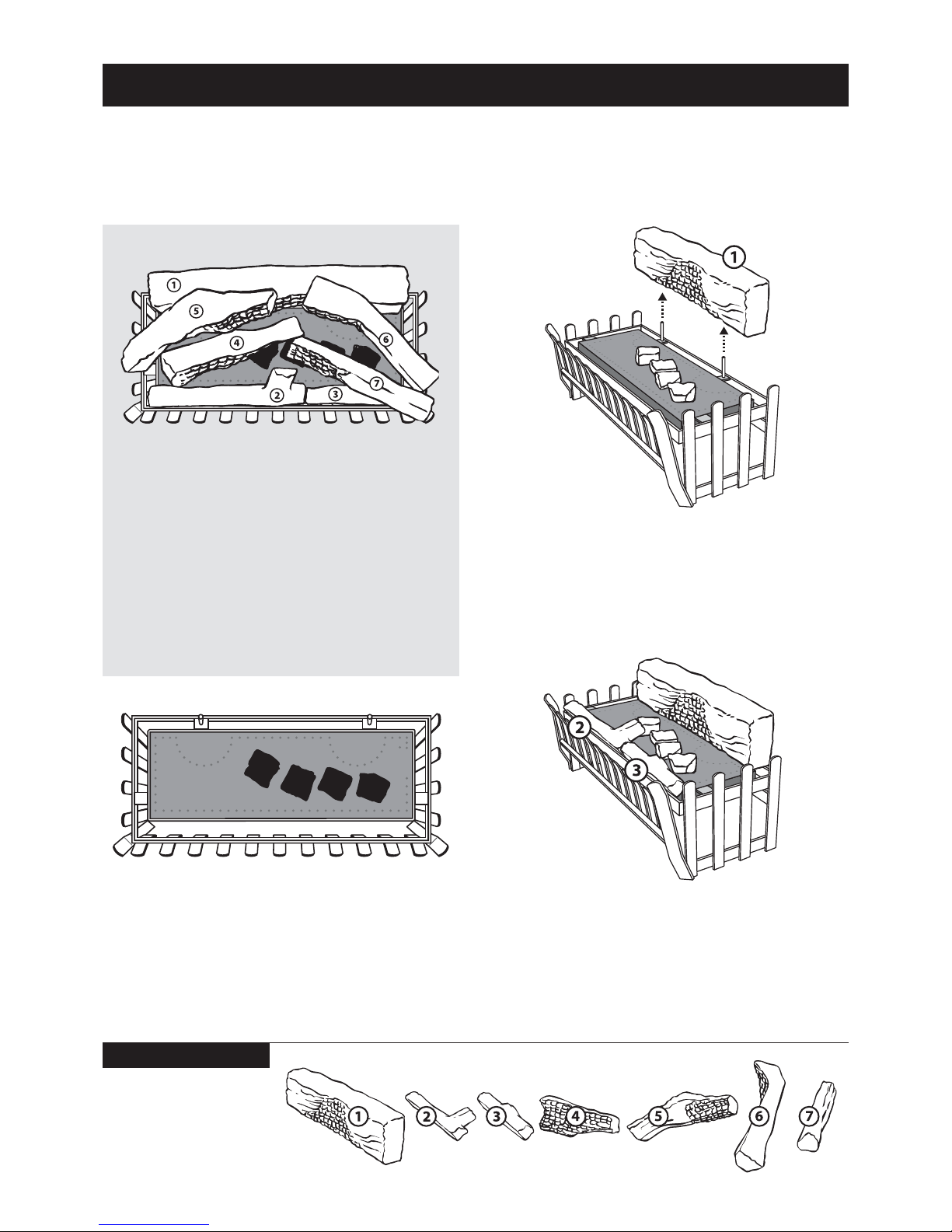
1. LOCATE 4 CERAMIC COALS: Four ceramic
coals are supplied with the burner base. These coals
must be laid in the position indicated on the drawing
with the taller coals on the ends and smaller coals
in-between.
2.
LOCATE LOG NO. 1: This is the largest log that
is positioned at the rear of the grate.Two locating pins
are positioned at the rear of the burner.The large log
has two holes on the underside to position in place.
3.
LOCATE LOG NO’S 2 & 3: Tw o front log no’s. 2
and 3 are supplied to fit into the space between the
metal frame and the ceramic base. These logs do not
cover the front burner ports but are designed to
deflect the front flame back into the fire.
LOGS
POSITIONING OF
ALL LOGS
• It is important to follow the log
recommended positioning.
• Not doing so can adversely effect the
operation of the appliance.
• This diagram shows the recommended log
positions, when viewed from above.
Only use logs supplied by
the manufacturer as other
logs may effect combustion
performance.
Ceramic log positioning for gas fires

Installation instructions Jetmaster Mark 4 Gas Log
Only use logs supplied by
the manufacturer as other
logs may effect combustion
performance.
Ceramic log positioning for gas fires
5. LOCATE LOG NO’S 5 & 6. Log no. 5 is
positioned onto the larger rear log on the left hand
side. The charred effect faces inwards and the bark
effect on the outside. The left hand side of the log is
positioned between the metal uprights on the side of
the grate. Log no. 6 is positioned in the same manner
but on the right hand side of the burner with the right
hand side of the logs positioned between the metal
uprights of the grate. Two pins are provided to firmly
position these two logs onto the large rear log (no. 1).
6.
LOCATE LOG NO. 7: The charred effect of the
log is positioned on the smaller coal in the centre of
the burner on the right hand side.
The right hand side of the log is positioned between
the front metal upright on the side.
4. LOCATE LOG NO. 4. This log is placed with the
thinner edge on the smaller coal.The charred effect is
facing towards the front of the burner.The whole log is
positioned on the burner base.
POSITIONING OF
ALL LOGS
• It is important to follow the log
recommended positioning.
• Not doing so can adversely effect the
operation of the appliance.
• This diagram shows the recommended log
positions, when viewed from above.
LOGS

Commissioning Procedure
Installed correctly the burner should not emit any
fumes into the room.The following procedure should
be undertaken to test that the unit is operating
correctly.
1. After unit has been operating for a short period a
smoke match, smoke tube, carbon dioxide analyser or
similar should be directed at the top opening of the
unit.
2. This procedure should be undertaken with the
following conditions in the room:
• Open or closed windows
• Operation of extraction/exhaust fans, range
hoods etc
• Operation of other gas appliances
• Operation of optional appliance fan at any speed.
3. Should any spillage be detected the cause must be
rectified before allowing commissioning of unit.
User Instructions:
1. WARNING NOTE: Properly installed and operated
this appliance will not leak gases. Persistent fume
emission must not be tolerated. If fume emission does
exist, then the following immediate action should be
taken.
A. Open doors and windows to ventilate room.
B. Turn the fire off.
C. Check for flue blockage and clear if necessary.
D. Do not attempt to relight the burner until the cause
of the emission has been identified and rectified. Should
assistance or advice be required contact nearest agent
or Jetmaster.
E. The gas grate is recommended for use in a
Jetmaster firebox which has been designed to ensure a
proper draw and to eliminate emission spillage.
2. Initially the Jetmaster coal fire may burn with a
slightly blue flame. After approximately 20 minutes the
fire will settle down and burn with a yellow flame.
3. As with all gas appliances your gas coal fire should
be regularly serviced.We recommend once each year.
Contact your nearest Jetmaster authorised agent to
provide service. The routine for an authorised person
to follow has been set out in an attached leaflet.
4. PLEASE NOTE: Only logs provided by Jetmaster
should be used with this appliance.
5. DO NOT place articles on or against this appliance.
DO NOT use or store flammable materials near
this appliance.
DO NOT spray aerosols in the vicinity of this
appliance whilst it is in operation.
Primarily a decorative appliance not certified as a
space heater.
6. The appliance is a live fuel effect product designed
to operate with luminous flames and may exhibit slight
carbon deposition.
Warranty
Provided the appliance has been correctly installed
according to instructions, Jetmaster guarantee the cost
of replacing parts and the labour in connection
therewith for a period of 12 months from the date of
installation. Should the appliance be subject to a service
contract the replacement of the parts and the service
involved in such replacement shall be at no charge to
the owner and the Warranty shall be extended to 3
years (provided of course the appliance had been
continuously serviced by an approved Jetmaster agent).
Installation instructions Jetmaster Mark 4 Gas Log
For further information contact Jetmaster Australia
10 Martin Avenue, Arncliffe NSW 2205 T: 02 9597 7222 F: 02 9597 7622
E: sales@jetmaster.com.au W: www.jetmaster.com.au
 Loading...