


INTERNATIONAL GAS
CONVECTOR BOX
For Zero Clearance Installations
THIS MANUAL CONTAINS INSTRUCTIONS
FOR ASSEMBLY AND INSTALLATION
Please read this entire manual before you assemble,
install and use the International Gas Convector Box.
JETMASTER (VIC) PTY LTD
ACN 005 872 159 ABN13 659 821 337
444 Swan St. Richmond VIC 3121 PO Box 5051 Burnley 3121
Phone: (03) 9429 5573 Fax: (03) 9427 0031
Website: www.jetmaster.com.au Email: info@jetmastervic.com.au

TABLE OF CONTENTS
SAFETY NOTES 3
Before Installation ................................................................................................ 3
Important Safety Notes ..................................................................................... 3-4
Ventilation Requirements .......................................................................................5
PRODUCT INFORMATION 6
Identify Components ............................................................................................ 6
Dimensions ....................................................................................................... 7-8
ASSEMBLY 9
Zero Clearance Casing ................................................................................... 9-10
Assembly of Gather to Convector Box .............................................................. 11
Assembly of the Zero Clearance Casing & Convector Box ......................... 12-13
INSTALLATION 14
Frameout Into Room .......................................................................................... 14
Flush Wall Installation ........................................................................................ 15
Gas Convector Positioning ................................................................................ 16
Flue Installation ............................................................................................. 16-17
Gas & Power Connection .................................................................................. 17
Gas Burner Installation ...................................................................................... 17
Flue Termination ................................................................................................. 18
Summary taken from the gas installations Australian standards ...................... 19
How to fit Fascias ............................................................................................... 20
WARRANTY 21
For Service and Spare Parts contact Jetmaster on (03) 9429 5573.

3
SAFETY NOTES
Before Installation
The Gas Convector Box shall be installed only by authorised personnel in
accordance with the manufacturer’s installation instructions, local gas fitting
regulations, municipal building codes, electrical wiring regulations, and any other
statutory regulations.
Contact local building authorities about restrictions and installation inspections
that may be required. If in doubt contact your local dealer or Jetmaster’s head
office.
Important Safety Notes
• When installing the International Gas Convector Box for Zero Clearance
Installations and the Gas Burner, particular attention should be paid to fire
protection. If this Gas Convector Box is not properly installed a house fire may
result. To reduce the risk of fire, follow these installation instructions and the
Gas Burner installation instructions carefully.
• RISK OF FIRE! Do not burn materials inside this Gas Convector Box. This
is NOT a wood stove and has not been designed for this purpose. Burning
materials inside the Gas Convector Box can result in damage to the unit,
house fire and/or death.
• Comply with all minimum clearances to combustibles as shown in this manual
and in the Gas Burner installation instructions.
• Do not connect to any air distribution duct or system.
• Do not operate without fully assembling all components. Operating your
Gas Burner and Gas Convector Box without all the components properly
assembled will void your warranty and could present a serious safety hazard.
• An approved gas cowl with a minimum cross-section of 40,000 sq mm must
be fitted to the top of the flue or chimney.
• All open gas fires require fixed fresh air vents in the room. See page 5 for
ventilation requirements.
. . . continued next page
IMPORTANT - PLEASE NOTE
Failure of the gas fitter to install the appliance
as per manufacturer’s specifications and in line
with the Gas Code will void the warranty.

4
SAFETY NOTES
Important Safety Notes
• Air movement systems - A decorative gas log fire must not be installed
where the operation of any ventilation system, fan or air blower could under
any circumstances cause the air pressure to be less than atmostpheric at the
appliance, or otherwise adversely affect the operation of the appliance.
• Do not block or restrict chimney or flue opening.
• After installing the appliance, check that the chimney/flue system draws well.
• Jetmaster recommends that all gas fires be serviced every year.
• All gas units must be fitted by a licensed gas fitter.
• It is the responsibility of the gas fitter to follow the regulations set out in
the Gas Code that dictate the procedures to follow when installing a gas
appliance, particularly regarding gas pipe sizing and checking of pressures.
(see summary page)
• For installation of the gas burner, see instruction manual supplied with gas
burner.
. . . continued
IMPORTANT - PLEASE NOTE
Failure of the gas fitter to install the appliance
as per manufacturer’s specifications and in line
with the Gas Code will void the warranty.

5
SAFETY NOTES
Ventilation Requirements
ROOMS WITH GAS OPEN FIRES
REQUIRE FRESH AIR VENTS
AS PER GAS REGULATIONS
FOR EXAMPLE:
1 OFF: WOODFLOW VENT:
430mm
125mm
OR: 2 OFF VENTS REQUIRED:
125mm
270mm
Ventilation - An opening to outside with a minimum free ventilation area of 400
square centimeters shall be provided for each decorative gas log fire.
Note: The chimney in which the appliance is installed is not to be considered as
a ventilation opening.

6
PRODUCT INFORMATION
Identify Components
The Gas Convector Box for Zero Clearance Installation and Flue Kit components
are identified below:
Top
RH Side
Cover
Cone
LH Side
Screws
Supplied
Front
Rear
Outer Flue × 3
1.2m
Cowl
Inner Flue × 3
1.2m
Gather
Nut & Bolt × 2
Surround
Convector Bo
x
Knock Out Discs
A
B
C

7
PRODUCT INFORMATION
Dimensions
The following tables and diagram show dimensions of the Gas Convector Zero
Clearance Casing sizes available:
E
D
C
B
A
Gas Inlet
Model A B C CD E
900
1050
700
700
910
910
870
1020
425
425
700
850
1250 620 825 1220 425
1050
Model Inner Outer
Flue Size
1050
700
850
225
200
250
275
250
300

8
PRODUCT INFORMATION
Dimensions
The following tables and diagram show dimensions of International Gas
Convector Box:
Gather
Nut & Bolt × 2
Surround
Convector Bo
x
Knock Out Discs
A
B
C
Model A B C
800
950
345
345
650
650
700
850
1150 345 570
1050

9
ASSEMBLY
IGC Zero Clearance with 100mm Trim Installation Instructions
1. Bolt gather onto the top of the IGC,
using the bolts provided
2. Slide 100mm trim over the existing
50mm flange of the IGC.
3. Assemble the Zero Clearance
casing:
- The casing comes in two pieces.
Unfold the side panels of the
large piece so that they sit at 90
degrees to the central panel. This
forms the back and sides of the
Zero Clearance casing.Stand this
upright to create the body of the
casing. Fold down the tabs around
the top of the back and sides.
- Fold the second piece according to
the perforations, creating a top and
front panel, and a front lip.
- Place the top/front panel over the
sides and back of the casing. Line
up the holes and attach,using selftapping screws or pop-rivets.
4. Lift Zero Clearance casing over the
IGC and gather and attach using
three screws on each side.
5. The IGC Zero Clearance casing
with 100mm trim is now complete.

10
ASSEMBLY
Zero Clearance with UK Front Installation Instructions
Ensure that there is sufficient clearance
around the IGC and that the IGC is
sitting flush with the plaster,to allow
the UK front to fit flat and flush with the
plaster.
The frame must have a gap of minimum
75 mm from the hearth to allow the
convected air to circulatearound the
IGC.
The use of heat resistant plaster is
recommended but not a requirement.
1. Bolt gather onto top of the IGC, using
the bolts provided.
2. Slide the sub-frame over the existing
50 mm flange of the IGC.
3. Assemble the Zero Clearance
casing.
- The casing comes in two pieces.
Unfold the side panels of thelarge
piece so that they sit at 90 degrees
to the central panel.This forms the
back and sides of the Zero Clearance
casing. Stand this upright to create
the body of the casing. Fold downthe
tabs around the top of theback and
sides.
- Fold the second piece according to
the perforations, creating a top and
front panel and a front lip.
- Place the top/front panel over the
sides and back of the casing.Line
up the holes and attach, using selftapping screws or pop-rivets.
4. Lift Zero Clearance casing over the
IGC and gather and attach using
three screws on each side.

11
ASSEMBLY
Zero Clearance with UK Front Installation Instructions
5. Fitting the brackets
Step 1. These parts should already be pre-
assembled. If not,then screw the R/H top slide
bracket to the R/H top fixed bracketusing an
M8x12mm long screw. Leave the screw slack at
thisstage so that the top bracket can slide up and
down.
Step 2. Locate and bolt both assembled top
brackets onto the deflector plate ends. Leave the
bolts loose.
Step 3. Mount the deflector plates with brackets
onto the sub-frame bypushing the brackets out
so that they fix against the sub-frame.Tighten
the bolts to fix the deflector plate on to the subframe, leaving the topslide brackets loose.
. . . continued

12
ASSEMBLY
Zero Clearance with UK Front Installation Instructions
Step 4. At this point, slide the top bracket up until it is 1mm above the top
of the sub-frame, ensuring that the edge of the top slide bracket is hard up
against the front surface of the sub-frame.Check that the leftand right hand
fixed brackets are located centrally and that the top slidebrackets are 1mm
higher than the sub-frame and are parallel with the top edge of the sub-frame
Step 5. At this stage, it is easier to fit
the gas burner into the firebox.
6. Fitting the UK front.
• Before offering up the UK front, ensure that the two lower slide boltsare pushed
fully to the centre of the fire so that they do not foul thesub-frame when offering
the UK front up to the sub-frame for fitting.If they have moved during transit then
slacken the M8x16mm screwsand slide the bolts towards the centre. Then retighten them. Screwa grub screw just a couple of threads into the end of each
slide bolt.
• Now offer up the UK front so that it rests on the top brackets and itlocates
between the sub-frame. Insert an M8x16mm long screw intoeach of the top
holes of the UK front and screw them hand tight intothrough, into the top slide
brackets.
. . . continued

13
ASSEMBLY
Zero Clearance with UK Front Installation Instructions
• Now reach through the frame and working
from the inside, slacken the two right hand
M8x16mm long screws that hold the slide
bolts in place. Slide the bolt hard behind
the sub-frame, then fully tightenthe two
M8x 16mm long screws. Repeat with the
left hand side. Now carefully tighten the
grub screws in the end of the right and
lefthand slide bolts so that they push
against the inside of the sub-frame, thus
pulling in the UK front and clamping it
onto the sub-frame.
DO NOT OVER-TIGHTEN THE SCREWS.
• Finally return to the screws at the top of
the UK front. First ensure that the UK front
is located correctly and that the UK front
just clears the wall above the fire. Now
fully tighten these two top screws.
. . . continued

14
A
B
C
3 pin fan base
wired to
Isolation
switch.
(if applicable)
Gas supply
line
Nominal to suit accessories
Eg. Mantelpiece.
A
C
300mm
min
200
mm
min
200
mm
min
HEARTH
Model A B C
950950
450
700
950
1100
450
850
900
1300
450
1050
Studs on edge
Internal
Depth
Frame opening
height.Taken
from finished
hearth level
Frame opening width
INSTALLATION
Frameout Into Room
The diagrams and table below show
dimensional details for constructing a
timber frame which protrudes into the room.
Note: Dimension ‘B’ in the table is measured
from the top of the hearth.
No hearth is required
but for added
safety a hearth is
recommended.
When using a
Jetmaster fascia
allow extra depth
to framing.

15
C
A
300mm
min
200
mm
min
200
mm
min
HEARTH
Model A B C
950
950
950
1100
450
450
700
850
900
1300
450
1050
A
B
C
Gas supply
line.
3 pin fan
base
wired to
Isolation
switch.
(if applicable)
Studs on edge
INSTALLATION
Flush Wall Installation
The diagrams and table below show
dimensional details for constructing a
flush wall installation.
Note: Dimension ‘B’ in the table is measured
from the top of the hearth.
No hearth is required
but for added
safety a hearth is
recommended.
When using a
Jetmaster fascia
allow extra depth
to framing.

16
INSTALLATION
Gas Convector Positioning
1. Position the Gas Convector and Zero Clearance casing at the same height
above the floor as your hearth. (minimum 6mm non-combustible material)
2. Push the Zero Clearance Casing and the Convector Box back into the cutout.
Ensure the power cord is not touching the Zero Clearance housing as shown
right.
3. Ensure air-intakes at bottom of Gas Convector Zero Clearance Casing are not
obstructed.
4. Maintain 25mm clearance from Zero Clearance Casing to combustible
material on back and sides.
Flue Installation
1. This Gas Convector Box must be installed with a minimum of 3 x 1200mm
lengths of flue or more as required (see section referring to clearance above
roof on page 18 of this installation manual).
2. The flue must fit over the spigot as shown in diagram 1, with the corrugated
end of the flue facing upwards. The flue must NOT fit inside the spigot, if this
is the case then you have an incorrectly sized flue. The corrugated end of the
flue should NOT be fitted as shown in diagram 2, this is INCORRECT.
3. Rivet inner flue to collar of gather at three places.
4. Rivet all further inner flues at three places.
5. Using double skin flues space inner and outer flues using 3 x 25mm self
tapping screws through outer casing at bottom, at each join and at top. Also
ensure that flues are ventilated at top and bottom, and when using a cover
cone drill a series of holes into the outer flue below the cover cone to ensure
adequate ventilation.
diagram 1 diagram 2

17
INSTALLATION
Flue Installation
6. Maintain a clearance of 25mm from outer flue to combustible materials.
7. Flash flue penetration at roofline with appropriate flashing to suit roof material.
If using a collar style flashing ensure it is suitable for heat operation.
8. Fit gas cowl. See page 3.
9. Long flue runs will require bracing to nearby framework. Use a noncombustible material such as hoop iron. Brace at 1500mm intervals.
10. The base beneath the unit must be made of non-combustible materials of
no less than 6mm. No hearth is required but for added safety a hearth is
recommended.
11. Framing
a) Construct timber frame, laying studs at face of fireplace on edge.
b) Keep clearance from top of unit 25mm.
c) Note that depth requirements vary with the use of a cast iron fascia.
d) Overall frame width will be determined by size of selected mantelpiece.
12. Plaster
a) Firecheck plaster is recommended with installations using a UK front.
a) Unit must be installed and flue run PRIOR to plastering.
b) The Zero Clearance casing has a location channel for plaster to slot into.
This may be the final chosen finish.
c) With a cast iron fascia, cut the plaster around the fascia. Keep the face of
the plaster and the fascia flush to fit the mantel.
Gas & Power Connection
To be performed by an authorised person.
1. If applicable, provide an electrical three-pin fan base to the inside back left
hand corner of the frame out. Hard wire from this to an external isolating
switch generally mounted on the outside of the fireplace recess.
2. Prepare the gas connection as detailed in the Gas Burner Installation
Instructions. The gas line is to enter the right hand side of the recess to align
with the gas inlet as shown on page 7.
Gas Burner Installation
Fit your gas burner into the Convector Box as per the instructions supplied
with the gas burner.
. . . continued
18
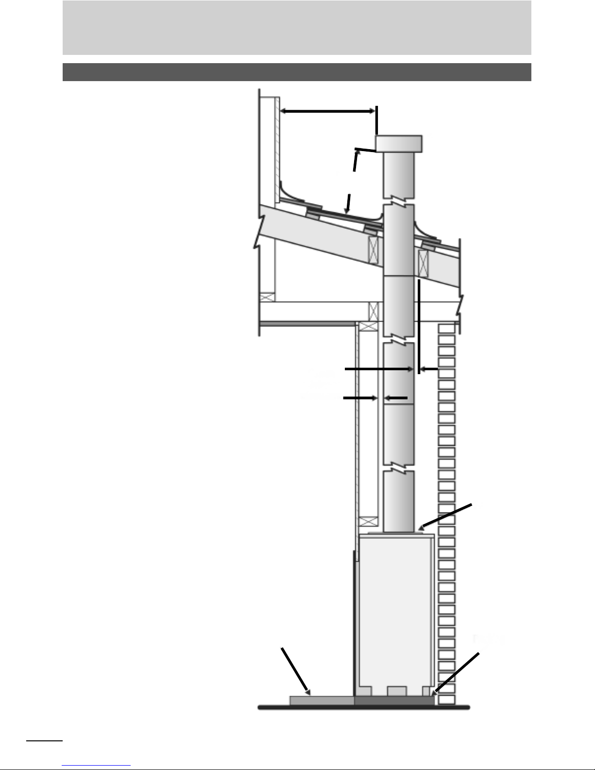
INSTALLATION
Flue Termination
1 meter
Flue Cowl
500 mm
Flashing
25mm
minimum
Hearth
Packing
Flue Outlet
The Flue Terminal shall be
located so that wind from any
direction is not likely to create
a downdraught in the flue.
A Flue Cowl, AGA Aprroved
to AG604 must be fitted to
the end of the flue pipe. The
minimum flue length must not
be shorter than 3.5 metres.
Maintain a minimum of 500mm
from the bottom of the flue
cowl to the nearest part of
the roof if the flue cowl is at
least 1m from a neighbouring
structure. If less than 1m, the
flue terminal must be located
at least 500mm above that
structure. Refer to AS5601 2000 (AG601) sections 5.13.6.2
and 5.13.6.4 to ensure that the
location of the flue terminal
fully complies for installations
with a trafficable roof, a
chimney, another flue terminal
or near any openings into a
building.

19
SUMMARY
SUMMARY TAKEN FROM THE GAS INSTALLATIONS
AUSTRALIAN STANDARDS
AS5601-2002 AG601-2002
IMPORTANT: THIS IS A SUMMARY ONLY. THE GAS FITTER MUST REFER TO
THE GAS INSTALLATIONS AUSTRALIAN STANDARDS IN DETAIL.
Appendix F Sizing Consumer Piping
- New Consumer Piping Systems
When sizing a new consumer piping system, consideration should be given to
foreseeable future needs.
- Existing Consumer Piping Systems
When an additional appliance is to be connected to an existing consumer
piping system, the existing piping, metre and regulator should be checked to
ensure that adequate capacity is available for the additional load.
- Information Required Prior To Pipe Sizing
The following information is required prior to pipe sizing:
a. The type of gas, including the heating value and relative density.
b. The gas consumption of each appliance.
c. An allowance, if any, where there is a probability that not all appliances will
be used at the same time.
d. The pressure available at the start of the consumer piping.
e. The allowable pressure drop shall be such as to ensure that at least the
minimum inlet pressure required by the appliance is available at the
appliance.
f. The proposed layout of the consumer piping system including all pipe
lengths and the location of each appliance.
NOTE: See tables in this appendix

20
INSTALLATION
HOW TO FIT FASCIAS
1. Use lugs and bolts provided and attach to flange on firebox.
OR
2. Use masonry plugs and drill through corners of fascia and attach to bricks.
OR
3. If neither of the above is suitable, then use heat resistance bonding silicon.
Note: Mantelpiece will hold fascia in position.
100mm Stainless Steel Trim Method for Attachment
1. Score the back of the stainless steel trim and the surface to which the trim will
be attached, to allow the two surfaces to adhere well to each other.
2. Place a bead of Silicone onto the back of the stainless steel trim.
3. Place another bead of Liquid Nails around the outer edge of the frame. This
will cure quickly and hold the frame into position.
4. Clamp the trim onto the unit for 24 hours until the adhesives have cured.

21
WARRANTY
Provided the Jetmaster Gas Convector Box is installed
according to Jetmaster instructions and a Jetmaster Gas Burner
is used, the unit* is unconditionally guaranteed for a period of
10 (ten) years from the date of installation of the fireplace.
*Not including glass doors, gas burner or fan.
INSTALLER’S NOTE:
Please discuss all relevant safety issues with the owner and pass the
operating instructions on to the owner after the installation has been
tested and signed off by the local municipality as a safe installation.
Jetmaster (Pty) Ltd.
Melbourne:
444 Swan Street
Tel: +61 (03) 9429 5573
Fax: +61 (03) 9427 0031
NEW ZEALAND
Auckland:
12 Tawari Street
Mt Eden
Tel: +64 (09) 623 6996
Fax: +96 (09) 623 6997
Sydney:
10 Martin Avenue Arncliff
Tel: +61 (02) 9597 7222
Fax: +61 (02) 9597 7622
SOUTH AFRICA
Gauteng:
1316 Clubhouse Street
Maraisburg, Johannesburg
Tel: +27 (011) 474-2100/4
Fax: +27 (011) 474-2144
www.jetmaster.co.za
AUSTRALIA

22
NOTES

23

JETMASTER (VIC) PTY LTD
ACN 005 872 159 ABN13 659 821 337
444 Swan St. Richmond VIC 3121 PO Box 5051 Burnley 3121
Phone: (03) 9429 5573 Fax: (03) 9427 0031
Website: www.jetmaster.com.au Email: info@jetmastervic.com.au
 Loading...