

Page 1

1. Introduction
The Max BEC 2D is a linear voltage regulator, to provide power for the receiver and servos used
in your models. For increased safety and reliability of this device, a magnetic switch is used to
switch the unit on and off. The Max BEC 2D is fully compatible with the Jeti Duplex System and
can also be operated using the Jeti Box terminal.
To provide power to the BEC, a 2-cell LiPo/LiIon battery can be used or a 5 to 6-cell NiMh/NiCd
battery pack. The voltage regulator supplies a constant voltage to your receiver and servos,
providing smooth servo motion regardless of the discharge state of batteries. For maximum
reliability, two battery packs can be used to provide power and the BEC features two LED's,
indicating the connection state of the the connected packs.
The MAXBEC2D can be monitored and configured via the Jeti Box, either by direct connection, or
wirelessly using the Jeti Duplex system. This allows the input voltage, temperature and output
voltage to be monitored but also, the output voltage can be configured and alarms can be set for
input voltage and temperature as required.
The system uses the 2.4GHz band to communicate, which allows not only data transmission, but
also the receiving of data back from the system. During operation, telemetry data allows the
condition of the system and any measured values to be displayed on the Jeti Box. Switching the
BEC on and off is performed via the special magnetic switch and key, which simply needs to
make contact with the face-plate in the correct orientation for a short period of time to switch the
unit on or off.
2. Description
2.1 MAXBEC2D
The supply batteries are connected to the MAXBEC2D via the two pairs of 1.5mm2 wires. These
wires do not have a plug fitted.
The stabilised ouput power is delivered via one pair of 1.5mm2 wires with an MPX type plug
already fitted for your convenience. The output voltage may be adjusted by using the jumper next
to the output wires. For programming and monitoring the unit can be connected either to the data
socket of your Duplex receiver, or directly to your Jeti Box. Connecting the MAXBEC2D to your
Jeti Box does not require that a separate power-supply is connected to the Jeti Box, if the BEC is
switched-on.
Page 2
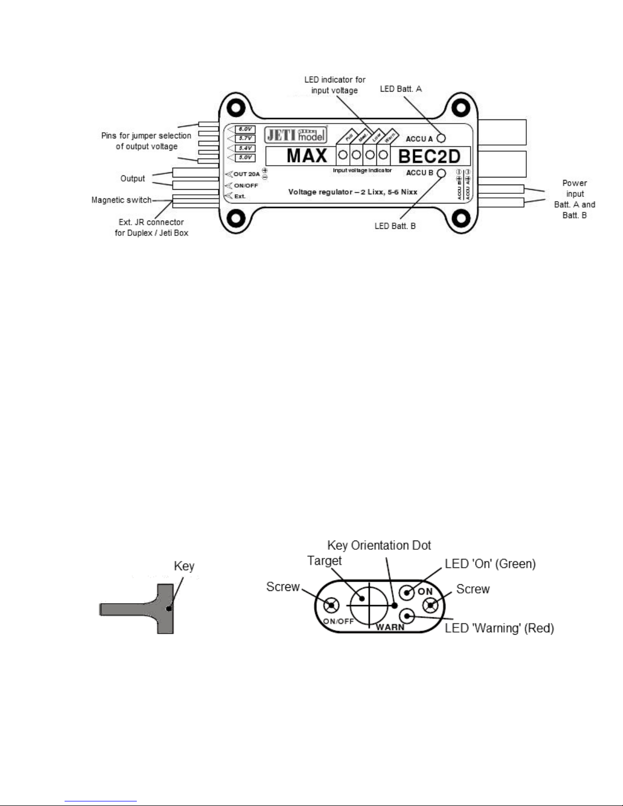
2.2 Magnetic Switch
The magnetic switch is used to switch the BEC on or off. The switch consists of a switch-plate,
which receives the magnetic key and also the magnetic key itself.
The switch-plate is connected to the BEC by a three-wire cable and features two LED's. The
green LED indicates that the BEC is active. The Red LED indicates a warning condition.
If the green LED is blinking, this indicates that the magnetic key is present, but the unit is not
switched on.
If the green LED is continuously active, this indicates that the BEC is active and ready to power
your receiver and servos.
If the red LED is continuously active, this indicates that the input voltage is below the preset
threshold. (This LED has the same function as the Warning LED on the main unit)
3. Circuits
3.1 Powering the Max BEC 2D
Page 3
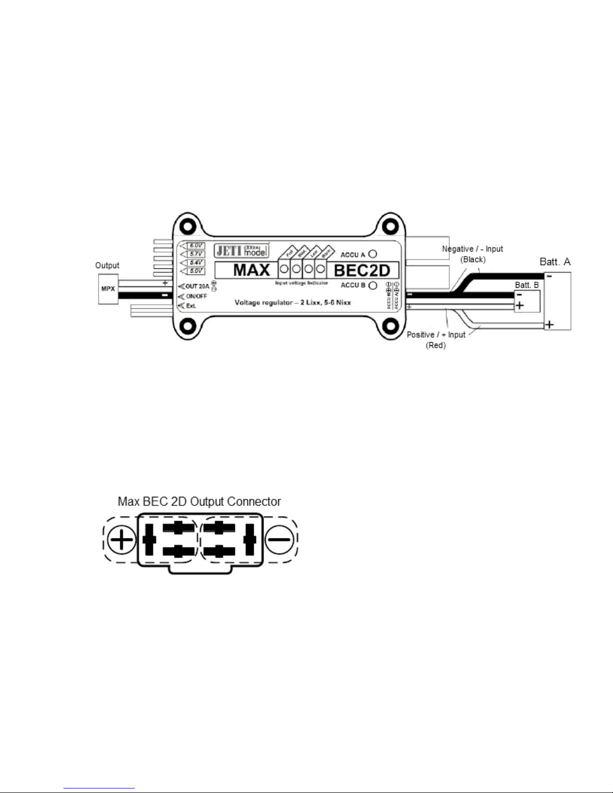
The Max BEC 2D can be powered by up to two batteries. These can vary by cell-count and
chemistry and the BEC will always take power from the battery with the highest voltage. If both
batteries have the same voltage, then the BEC will take power from both batteries together. LED
Batt. A and/or LED Batt. B will indicate which battery the power is being drawn from. This can
also be determined from the Jeti Box.
If only one battery is to be used, it can be connected to battery input A or input B.
To connect your device(s) to the BEC, either solder your wires (Please use wire of at least 1mm2
diameter or larger, depending on your anticipated load) to the MPX output connector of the BEC
or use the Jeti MPX/3xJR cable, available separately. The Duplex EPC receivers, such as the R6
EPC, R8 EPC, R12, R14 and R18 are already fitted with a compatible MPX plug.
3.2 Communication with the Max BEC 2D
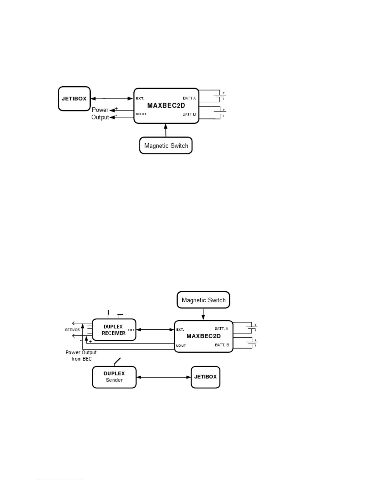
3.2.1 Connecting to the Jeti Box
Connect the BEC to the Jeti Box using the red JR connector from the BEC. Plug this into the
appropriate socket of the Jeti Box (The socket marked signal, +, -).
Connect the power-supply battery to the BEC and switch-on the BEC using the magnetic switch.
For this setup, there is no need to connect a supply battery to the Jeti Box as it will be powered
by the BEC. There is no wireless data transfer in this scenario.
Page 4
Please note that in this configuration, no alarms will be generated because these rely on the
wireless data transfer and acoustic alarm of your Duplex transmitter module.
3.2.2 Connecting the BEC to a Duplex Receiver
Connect the BEC to the receiver using the red JR connector from the BEC. Plug this into the
socket marked 'Ext.' on the Duplex receiver.
Connect the supply battery to the BEC, not forgetting to connect the power output of the BEC to
your receiver!
Now the Jeti Box can be connected to your transmitter module for programming and monitoring of
the system. Switch on your transmitter and then use the magnetic key to switch-on the BEC.
3.2.3 Connecting the BEC to a Duplex Expander
Connect the BEC to the Expander using the red JR connector from the BEC. Plug this into any of
Page 5

the sockets on the Duplex Expander.
Connect the Expander to the Duplex Receiver into the socket marked 'Ext.'. Do not forget to
connect the BEC to the receiver.
Connect the power-supply battery to the BEC and connect the Jeti Box to the Transmitter module
and switch-on the transmitter.
The BEC can now be switched-on using the magnetic key.
4. Menu Navigation
For parameter setting and monitoring of the Max BEC 2D, the Jeti Box is used.
After connecting the Jeti Box according to the above instructions, the screen shows the
identification of the unit, the temperature and the voltage of each supply battery. The active
power-supply input is marked by a "*" character.
By pressing the 'D' (Down) button on the Jeti Box, we enter the menu for the Max BEC 2D.
4.1 ACTUAL VALUE - Actual Values
Actual Value - By pressing the 'D' (Down) button of the Jeti Box, we can view the actual
measured values.
Acc. Input Voltage - Shows the actual voltage of the power-supply batteries A and B.
Temperature - Shows the temperature of the Max BEC 2D
Actual Output Voltage - Shows the actual voltage being output by the BEC.
4.2 MIN / MAX - Minimum and Maximum Values
Min / Max - By pressing the 'D' (Down) button, we can view the extremes of temperature and
Page 6

voltage. Please note that these values are deleted automatically or can be deleted manually
using the Erase Data menu option. The values are automatically erased when the unit is switched
on and the input voltages exceed those specified in the Trigger Level menu option.
Accum. A MIN/MAX - Shows the minimum and maximum voltage of the battery connected to
input A.
Accum. B MIN/MAX - Shows the minimum and maximum voltage of the battery connected to
input B.
Temp. MIN/MAX - Shows the minimum and maximum temperature of the Max BEC 2D.
4.3 SETTING - Configuration Options
SETTING - By pressing the 'D' (Down) button, we can see the individual parameter settings of the
Max BEC 2D.
Erase Data - By simultaneously pressing the Left and Right button of the Jeti Box, all minimum
and maximum recorded values are erased (See also section 4.2)
Trigger Level - Set the voltage values, the first overshoot of which, the previously recorded
minimum and maximum values are erased and recording begins again (See also section 4.2)
Output (x.x) Volt - Set the output voltage of the BEC. Note that the output voltage of the BEC can
be set by jumper or programmed using the Jeti Box. By pushing the 'L' (Left) button, the BEC can
be configured purely by Jumper. By pushing 'R' (Right), the BEC output voltage can be set
directly from the Jeti Box, overriding the physical position of the Jumper.
Beep Volt. Alarm - Set the letter of the alphabet to be acoustically signalled from the transmitter
module when the input voltage falls below that specified by Trig. Level for WARN LED
Beep Temp. Alarm - Set the letter of the alphabet to be acoustically signalled from the transmitter
module when the temperature of the BEC exceeds the limit specified by Temp. Alarm (In the
Alarm menu - See section 4.4)
Trig. Level for WARN LED - The input voltage at which the red warning LED on the magnetic
switch-plate and on the BEC should become active. This is also the voltage at which the first
green LED should deactivate.
Step Value - The voltage value of each step between the green input voltage LED's on the BEC
(5.5-8.4V). The table below shows an example, assuming a step value of 0.4V and a trigger level
of 6.6V:
Page 7

4.4 ALARMS - Alarms
ALARMS - By pressing the 'D' (Down) button, we can scroll through the available alarms offered
by the MAXBEC2D.
Voltage Alarm A - Set the voltage at which point the alarm specified by the Beep Volt. Alarm
setting, will be sounded by the transmitter module for battery A. (See '4.3 SETTING -
Configuration Options')
Voltage Alarm B - Set the voltage at which point the alarm specified by the Beep Volt. Alarm
setting, will be sounded by the transmitter module for battery B. (See '4.3 SETTING -
Configuration Options')
Temp. Alarm - Set the temperature at which point the alarm specified by the Beep Temp. Alarm
setting, will be sounded by the transmitter module. (See '4.3 SETTING - Configuration Options')
5. Output Voltage Adjustment
The output voltage of the MAXBEC2D can be adjusted in two ways:-
• Using the short-circuit (or 'jumper') plug directly on the unit, the output voltage can be
adjusted from 5.0, 5.4, 5.7 to 6.0 volts. For this approach, the BEC must be configured
appropriately (See section 4.3 and refer to the Output (x.x) Volt configuration option)
Page 8

• Using the Jeti Box terminal, navigate to the Output (x.x) Volt setting (See section 4.3
SETTING - Configuration Options) and change to your desired value. This can be done in
steps of 0.1V independently of the position of the short-circuit/jumper plug.
The factory-default setting is that the output voltage is set using the short-circuit/jumper plug.
6. Powering On
The system is activated by an external magnetic switch that contains the circuitry for the
evaluation of magnetic fields with a diametrically polarized magnet. Since the magnet is
polarized, the orientation of the magnetic key is important when being offered to the switch-plate.
The magnet is supplied with an aluminium housing, which marks the correct orientation in which it
should be offered to the switch-plate. Please refer to the safety precautions outlined in section 8
for correct handling of magnets.
The switch is designed to be mounted on the fuselage of your model. When the key is offered to
the switch, the green LED will flash and after approximately 1 second, the LED will be
continuously lit, indicating that the BEC is now active.
For de-activating the BEC, the same principles apply. Offer the key to the switch in the correct
orientation. The green LED will flash and after approximately 1 second, the LED will go out, at
Page 9

which point the BEC is now switched-off.
The whole system remembers whether it has been switched-off or modified. If the BEC is
switched-on and the battery is disconnected, then the next time the battery is connected, the BEC
will immediately be switched-on. For safety and security, the BEC should always be switched-
off via the magnetic switch before disconnecting the battery power.
After connecting the power-supply battery and switching the BEC on via the magnetic switch, the
unit automatically checks the number of connected batteries. The BEC acknowledges a battery
connection if the input voltage on either input exceeds 1 volt. If at any time the input voltage drops
below 1 volt, then an error message 'X input error' is displayed, where X is A or B, to indicate on
which input the problem was detected. The error condition remains until the unit is switched-off
and the battery is disconnected.
Always follow the same procedure when switching on/off. To switch-on, first connect the
batteries and then use the magnetic switch to activate the unit. To switch-off, always use
the magnetic switch to turn-off the unit before disconnecting the batteries.
7. Installation
The BEC can be mounted in your model using the 4 mounting holes on the unit, along with the
rubber-grommets to reduce vibrations. The magnetic switch offers two mounting holes and the
upper-lid (or face-plate) should be used as a mounting template for this part of the unit. The latter
is designed to be mounted on the outside of the unit, being mechanically secured by the screws
included. This allows for easy switching on/off of the BEC and at the same time allows good
visibility of the green and red LED's on the face-plate of the switch.
To ensure safe and reliable operation of your BEC, please ensure an adequate flow of
cooling air to allow the heat-sink to dissipate heat.
8. Safety Precautions For The Manipulation Of Magnets
Since the MAXBEC2D contains magnetic components, it is necessary to follow some simple rules
Page 10

for the handling of magnets. The magnet is contained within a special holder made of aluminium.
1. Keep the magnet a safe distance from all devices that could be damaged by magnetic
interference: Televisions, Credit Cards, PC's and Pacemakers.
2. Keep magnets away from children, due to the risk of ingestion or injury.
9. Technical Specification of the MAXBEC2D
Technical Data MAX BEC 2D
Recommended Input Voltage 5.5 - 8.4 V
Maximum Input Voltage 16 V
Number of possible power-supply batteries 1 or 2
Adjustable Output Voltage 5.0 - 6.0V (0.1V Steps)
Maximum current (pulse) 20A
Continuous current 12A
Quiescent current 240µA
Maximum Power Dissipation 20 W
Operating Temperature -10°C to 130°C
Weight 85g
Dimensions 100 x 29 x 16 mm
Table showing the dependency between input voltage, output voltage and continuous
current capability
Number of power-supply cells (Input V.)
2 LiXX / 6 NiXX 8.33 A 10.00 A 11.76 A 12.00 A
Output Voltage (V) / Continuous Current (A)
5 V 5.4 V 5.7 V 6 V
3 LiXX / 10 NiXX 3.28 A 3.51 A 3.70 A 3.92 A
12 NiXX 2.44 A 2.56 A 3.70 A 3.92 A
Page 11

10. Warranty
The MAXBEC2D carries a warranty valid 24 months from the date of purchase under the
condition that it has been operated as per these instructions and there is no mechanical damage.
All servicing and repairs during and after the warranty period is carried out by the manufacturer.
The manufacturer hopes you enjoy this product: JETI model s.r.o. Příbor, www.jetimodel.cz
11. Menu Diagram for MAXBEC2D
Page 12

 Loading...