

Page 1
®
1
CZ
EN
DE
modeláøská elektronika
electronics for models
modellbau elektronik
modeláøská elektronika
electronics for models
modellbau elektronik
modeláøská elektronika
electronics for models
modellbau elektronik
modeláøská elektronika
electronics for models
modellbau elektronik
Návod k pouití
Directions for use
Gebrauchsanweisung
Page 2

2
CZ
JETIBOXjeuniverzálníkomunikaènínástroj,který roziøujemonostivyuiti
vechvyrobkù,kteréjsou oznaèenylogemJETIBOXcompatible.Pøehledným
zobrazenímhodnotasnadnýmnastavenímparametrù, pakmùetenaplno
vyuítjejichpotenciál.
Pouití JETIBOXu:
1.Mìøení íøky impulsù kanálových výstupù pøijímaèe
2.Generátor impulsù pro serva
3.Cyklovaè serv
4.Mìøení rychlosti serv
5.Komunikace s regulátory SPIN (viz. návod k obsluze k regulátorùm SPIN)
6. Komunikace se senzorovými regulátory pro støídavé motory (CAR)
7. Komunikace s pøijímaèi JBC
8. Komunikace se systémem DUPLEX
K aplikaci è.1 je zapotøebí pøijímaè s vysílaèem a pøijímaèové akumulátory (4,8-6V).
Akumulátory zapojte do edé zdíøky, pøijímaè do modré zdíøky na pravé stranì JETI BOXu.
K aplikacím è.2, è.3 a è.4 jsou zapotøebí pøijímaèové akumulátory (4,8-6V) a servo.
Akumulátory zapojte do , servo do .
V pøípadì zmìny aplikace musíte odpojit napájecí akumulátory z JETI BOXu a znovu je
aktivovat. Poadovanou aplikaci vyberte pomocí tlaèítek R a L. Pokud nemáte k dispozici Rx
akumulátory nebo zdroj napìtí (v rozsahu 4,8-6V) lze JETI BOX napájet z BECu regulátoru
(neplatí pro SPIN OPTO). JR konektor regulátoru pøipojte do zdíøky B (impuls (oranový vodiè)
do neoznaèené pozice). Pøipojte pohonné akumulátory k regulátoru a zapnìte vypínaè (neplatí
pro SPIN11).
edé zdíøky modré zdíøky
Výrobky komunikující
s JETIBOXem jsou oznaèeny logem
JETIBOX COMPATIBLE
Page 3
1.Mìøení íøky impulsù kanálových výstupù pøijímaèe
Pomocí této aplikace lze zmìøit íøku výstupního impulsu libovolného kanálového výstupu
Rx. Dále lze zmìøit napájecí napìtí pøijímaèových akumulátorù.
Do pøijímaèe zapojte pøijímaèové akumulátory. Pomocí propojky, která je dodávána spoleènì
s JETI Boxem, propojte s konkrétním kanálovým výstupem pøijímaèe. Zapnìte
vysílaè a pøijímaè. Na displeji se objeví IMPULS DETECTION, kde si mùete pøeèíst íøku
výstupního impulsu v ms a napìtí pøijímaèových akumulátorù.
2. Generátor impulsù pro serva
Tato aplikace JETI Boxu umoòuje generovat øídící impulsy pro serva a zároveò umoòuje
mìøit napájecí napìtí serva. Zapojte akumulátory a servo za pomocí tlaèítek L a P zvolte funkci
IMPULS GENERATOR. Pomocí tlaèítek si mùete mìnit rozsah od 1,024 ms do 2,047 ms, a to
po tisícinì ms nebo po setinì ms. Tato funkce je vhodná napø. pro nastavení støední polohy serva
(1,500 ms) bez pouití pøijímaèe a vysílaèe.
íøku impulsu lze nastavit pomocí vech ètyø tlaèítek:
Pomocí tl. L se impuls zuuje po 0,001 ms
Pomocí tl. D se impuls zuuje po 0,01 ms
Pomocí tl. U se impuls roziøuje po 0,01 ms
Pomocí tl. R se impuls roziøuje po 0,001 ms
3.Cyklovaè serv
V této aplikaci lze nastavit poèet cyklù, výchylku serva a rychlost cyklování. Slouí k ovìøení
ivotnosti, zahoøení a zkouce funkènosti serv.
modrou zdíøku
CZ
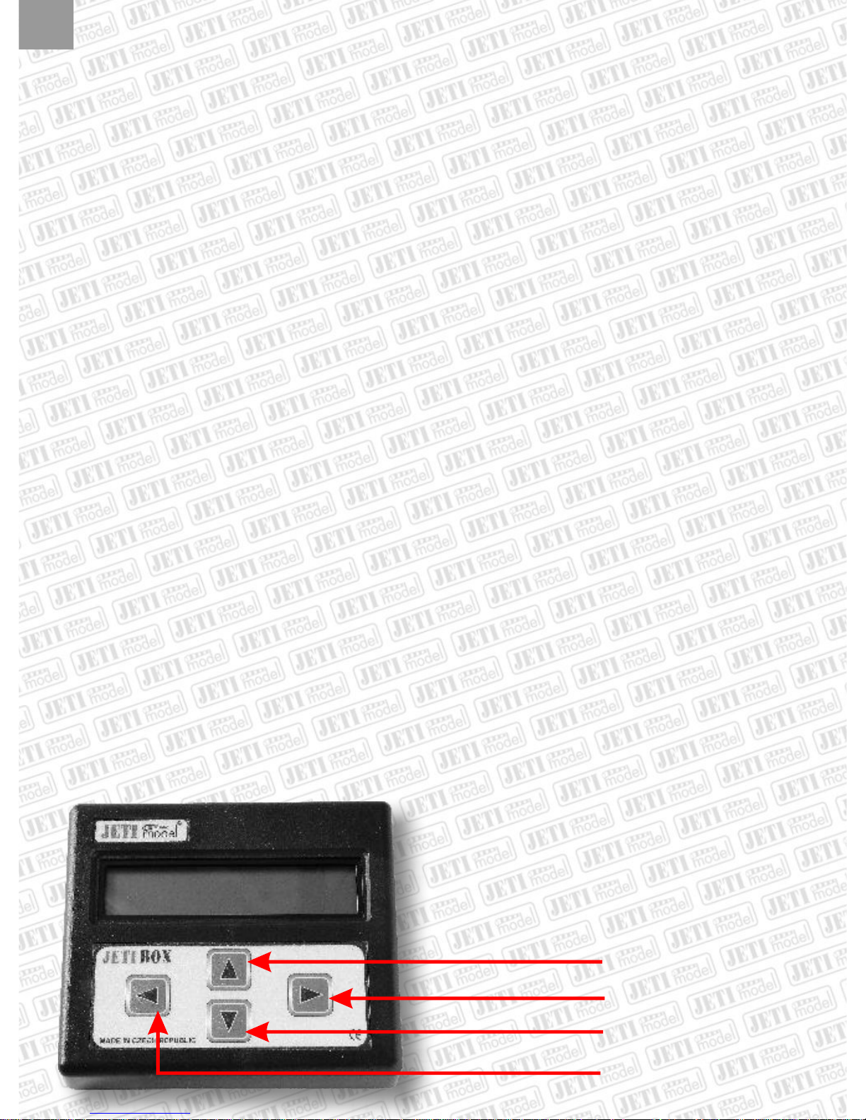
Tlaèítko nahoru
Tlaèítko vpravo
Tlaèítko dolù
Tlaèítko vlevo
U
R
D
L
3
Page 4

4
Zapojte akumulátory a servo za pomocí tlaèítek L a R zvolte funkci SERVO CYCLE.
Pomocí tlaèítek U a D zvolte poèet cyklù, a to od 10 do 990 (volba je po deseti cyklech).
Pomocí tlaèítek L a R lze nastavit rychlost, a to od 1 do 99. Rychlost v=1 znamená, e kadý
následující impuls se ve srovnání s impulsem pøecházejícím zmìní o 0,001 ms, a dosáhnete
nastavené hodnoty. (obdobnì v=20, znamená zmìnu o 0,020 ms). Perioda impulsù je 20 ms.
Pomocí tlaèítek U a D lze nastavit hodnotu, která udává velikost výchylky serva v µs, a to od
100 do 500 µs, od støední hodnoty 1,5 ms.
Pøi nastavené ?=500 µs se øídící impuls pro serva bude mìnit od 1,000 ÷ 2,000 ms (tzn.
1,500 ms ± 500 µs). Hodnota za # udává poèet cyklù, které jetì zbývají do konce testu.
Po skonèení testu se program vrací na zaèátek SERVO CYCLE.
4.Mìøení rychlosti serv
Pomocí tohoto mìøení jsme schopni zjistit èas, za který pøejde servo z jedné definované
polohy do druhé. Mìøení lze provádìt buï naprázdno nebo pøi nainstalovaném servu pøímo v
modelu pøi konkrétních pákových pomìrech.
íøku impulsu první krajní polohy serva lze nastavit v rozmezí od 1,024 ms do 1,400 ms a
druhou od 1,600 ms do 2,047 ms. Chceme-li zmìøit rychlost pøi pootoèení výstupní høídele
serva napø. o 60o, je tøeba toto nastavení provést napø. pomocí úhlomìru.
Zapojte akumulátory a servo, tlaèítky L a R nastavte funkci SERVO SPEED.
Pomocí tlaèítek U a D nastavíme první krajní polohu serva. Dále tlaèítkem R pøejdete na
nastavení druhé krajní pozice, kterou takté nastavíte pomocí tlaèítek U a D.
Odstartujeme mìøení.
Na displeji se zobrazí výsledný èas serva potøebný k pøejezdu z jedné nastavené polohy do
druhé v sekundách. Toto mìøení mùete libovolnì opakovat, popø. si nastavit jiné krajní polohy.
Pøejeme Vám mnoho pøíjemných chvil s naimi výrobky.
JETI model s.r.o, Lomená 1530, 742 58 Pøíbor, www.jetimodel.cz,
e-mail: jeti@jetimodel.cz
CZ
Page 5

5
EN
Products marked "JETIBOX COMPATIBLE"
communicate with JETIBOX
JETIBOX is a universal communication terminal, which can be used with any
JETI products that are marked JETIBOX Compatible (JBC). JETIBOX
Compatible products use powerful software to allow easy setup and reading
of data using a simple menu driven display on the JETIBOX terminal.
Application JETIBOX:
1. Measurement of receiver channel outputs pulse widths
2. Servo pulse generator
3. Servo cycler
4. Measurement of servo transfer speeds
5. Communication with controllers SPIN (see controller SPIN operating instructions)
6. Communication with sensor controllers for BLDC
7. Communication with REX JBC receivers
8.
For application #1 you need a receiver, transmitter and receiver batteries (4,8-6V). Plug
batteries into socket GRAY, receiver to socket BLUE, both on the right side of the JETI BOX.
For applications #2, #3 and #4 you need the receiver batteries (4,8-6V) and a servo. Connect
the batteries to socket first and the servo to socket .
In case of change of the application you must disconnect the supply battery from the JETI BOX
and activate them again. In order to choose the required application use the push-buttons
R and L.
If you do not have RX batteries or another kind of voltage source (range of 4,8-6V) you can
supply the JETI BOX from the BEC of the controller (do not for SPIN OPTO). Plug the JR
connector of the controller into socket (pulse (orange cable) into the unmarked position).
Connect the flight batteries to the controller an switch on the switch (if available).
Communication with SYSTEM DUPLEX
GRAY BLUE
GRAY
Page 6

6
1. Measurement of receiver channel output pulse widths
By means of this application the width of the output pulse of any arbitrary Rx channel
output can be measured. Furthermore, measurement of the receiver battery supply voltage is
also possible. Connect the receiver batteries to the receiver. With the aid of the connecting cable
as delivered along with the JETI Box connect socket with a definite RX channel
output. Switch on the transmitter and receiver. The display shows now IMPULS
DETECTION and you can read the values of the output pulse width in ms and the Rx
battery voltage.
2.Servo pulse generator
This JETI Box application renders the generation of servo controlling pulses as well as the
measurement of the servo supply voltage possible. By means of the push-buttons you can
change the range from 1,024 ms to 2,047 ms either in steps of thousendth or
hundredth of a ms. This function is for instance very well suited for setting the center position of
a servo (1,500 ms) without receiver and transmitter. Connect batteries and servo.
The pulse width can be set by means of all four push-buttons:
With push-button L the pulse becomes narrower in steps of 0,001 ms
With push-button D the pulse becomes narrower in steps of 0,01 ms
With push-button U the pulse becomes wider in steps of 0,01 ms
With push-button R the pulse becomes wider in steps of 0,001 ms
3.Servo cycler
In this application it is possible to set the number of cycles, the servo throw and the
cycling speed. This item serves for verification of longevity, burning in and function tests of
servos. Connect batteries and servo and choose by means of push-buttons L and R the function
BLUE
Button UP
Button right
Button dowm
Button left
U
R
D
L
EN
Page 7

7
SERVO CYCLE.
By push-buttons U and D set the number of cycles from 10 to 990 (setting in steps of ten
cycles). The speed can be set from 1 to 99 by push-buttons L and R. A speed of v=1 means that
every following pulse in comparison with the foregoing pulse will change by 0,001 ms until you
reach the limit position. (analogous v=20 means a change by 0,020 ms). The pulse period is
20ms.
By means of push-buttons U and D a value can be set which defines the servo throw in µs,
going from 100 to 500 µs from the center position of 1,5 ms. If the setting is ?=500 µs the control
pulse for the servos will change from 1,000 ÷ 2,000 ms (i. e. 1,500 ms ± 500 µs). The value after
the # gives the number of cycles which are still left until the end of the test.
When the test is finished the program returns back to the start SERVO CYCLE.
4.Measurement of servo transfer speeds
By means of this test we can find out how much time the servo needs to transfer from one
defined position to the other one. Measurements can be carried out without load or with the
servo directly installed in the model at real lever conditions.
The pulse width of the first limiting servo position can be set within a range of 1,024 ms to
1,400 ms and the second one within 1,600 ms to 2,047 ms. If we want to measure the speed
when the servo output shaft turns for instance by 60°, we have to adjust this angle for
instance with a protractor.
Connect the battery and the servo, by means of the push-buttons L and R select the function
SERVO SPEED.
By means of the push-buttons U and D set the first limit position of the servo. Proceed with
push-button R until you reach the second limit position, which also must be adjusted by
push-buttons U and D.
Start the test.
On the display you will read the resulting time in seconds, which the servo needs for the
transfer from one set position to the other one. This measurement can be repeated several
times or you can set different limit positions.
We wish you a pleasant time and much fun with our products.
JETI model s.r.o, Lomena 1530, 742 58 Pribor,
www.jetimodel.com, e-mail: jeti@jetimodel.cz
EN
Page 8

8
DE
Jeti Produkte, welche mit der JetiBox
kommunizieren, werden mit dem
Logo "JetiBox compatible" gekennzeichnet.
Anwendung JETIBOX:
1. Messung der Impulslänge der Empfänger-Kanalausgänge
2. Impulsgenerator für Servos
3. Servocycler
4. Messung der Servogeschwindigkeit
5. Kommunikation mit den Drehzahlstellern SPIN
(siehe Bedienungsanleitung zu den DS SPIN)
Für die Applikation Nr. 1 braucht man den Empfänger mit Sender und Empfängerakkus (4,8
6V). Die Akkus werden an die graue Buchse, der Empfänger an die blaue Buchse an der
rechten Seite der JETI BOX angeschlossen.
Zu den Aplikationen Nr. 2, Nr. 3 und Nr. 4 benötigen wir den Empfänger-Akku (4,8 - 6V) und
ein Servo. Die Akkus werden in die graue Buchse, das Servo in die blaue Buchse
eingesteckt.
Im Falle einer Änderung der Aplikation müssen die Akkus von der JETI BOX getrennt werden
und dann wieder angeschlossen werden. Die gewünschte Aplikation wählen Sie mit den Tasten
R und L.
Wenn Sie keine Empfängerbatterien oder eine andere Stromquelle (im Bereich von 4,8 6V)
zur Verfügung haben, kann die JETI BOX vom BEC des Drehzahlstellers versorgt werden. Den
JR-Stecker des DS stecken Sie in die Buchse B (Impuls ist das orangene Kabel, nicht näher
bezeichnete Position). Schließen Sie die Flugakkus an und schalten Sie den Schalter ein (gilt
nicht für SPIN 11).
6. Kommunikation mit den sensor Drehzahlstellern für BLDC
7. Kommunikation mit den Empfänger REX JBC
8. Kommunikation mit den DUPLEX-System
Page 9

9
1. Messen der Impulslänge der Empfänger-Kanalausgänge
Mit Hilfe dieser Aplikation kann die Impulslänge jedes beliebigen Kanal-Ausgangsimpulses
des Empfängers gemessen werden. Weiterhin kann die Versorgungsspannung des
Empfängerakkus gemessen werden. Schließen Sie den Empfängerakku am Empfänger an. Mit
Hilfe des Verbindungskabels, welches im Lieferumfang der JETI BOX ist, verbinden Sie die
blaue Buchse mit dem gewünschten Empfänger Kanalausgang. Schalten Sie den Sender und
Empfänger ein. In der Anzeige erscheint IMPULS DETECTION, wo sie die Impulslänge in ms
und die Spannung der Empfängerakkus ablesen können.
Impulsgenerator für Servos
Diese Aplikation der JETI Box ermöglicht die Generierung von Servo-Steuerimpulsen und
gleichzeitig die Messung der Servo-Versorgungsspannung. Schließen Sie die Akkus und das
Servo an und wählen Sie mit Hilfe der Tasten L und P die Funktion IMPULSGENERATOR.
Mit den Tasten können Sie den Bereich zwischen 1,024 ms bis 2,047 ms ändern, und dies in
Schritten von tausendsteln oder hundertsteln ms. Diese Funktion eignet sich z. B. zum Einstellen
der Mittellage des Servos (1,500 ms) ohne Verwendung des Empfängers und Senders.
Schließen Sie den Akku und das Servo an.
Die Impulslänge kann mit Hilfe aller vier Tasten eingestellt werden.
Mit der Taste L wird der Impuls in Schritten von 0,001 ms verkürzt
Mit der Taste D wird der Impuls in Schritten von 0,01 ms verkürzt
Mit der Taste U wird der Impuls in Schritten von 0,01 ms verlängert
Mit der Taste R wird der Impuls in Schritten von 0,001 ms verlängert
2.
3.Servocycler
Bei dieser Aplikation kann die Anzahl der Zyklen, der Servoweg und die
Zyklusgeschwindigkeit eingestellt werden. Man kann damit die Servolebensdauer testen, die
Servos Einbrennen und ihre Funktion testen.
DE
Button UP
Button right
Button dowm
Button left
U
R
D
L
Page 10

10
DE
Schließen Sie die Akkus und das Servo an und wählen Sie mit Hilfe der Tasten L und R die
Funktion SERVO CYCLE. Mit den Tasten U und D wählen Sie die Anzahl der Zyklen im Bereich
von 10 bis 990 (nur in Schritten von 10 Zyklen).
Mit den Tasten L und R kann die Geschwindigkeit von 1 bis 99 eingestellt werden. Die Ge-
schwindigkeit v=1 bedeutet, dass jeder nachfolgende Impuls im Vergleich zu vorangehenden
Impuls sich um 0,001 ms verändert bis der eingestellte Wert erreicht wird (Analog v=20 bedeutet
eine Änderung um 0,020 ms). Die Impulsperiode ist 20 ms. Mit den Tasten U und D kann ein
Wert eingestellt werden, der die Größe des Servoweges in vom Mittelwert 1,5 ms im Bereich
von 100 bis 500 angibt.
Bei eingestelltem =500 wird sich der Steuerimpuls für Servos von 1,000 ÷ 2,000 ms (d.
h. 1,500 ms ± 500 s) verändern. Der Wert hinter # gibt die Anzahl der Zyklen an, die bis zum
Testende verbleiben.
Nach Beendigung des Tests kehrt das Programm zurück zum Anfang SERVO CYCLE.
4.Messen der Servogeschwindigkeit
Durch Anwendung dieser Messung können wir die Zeit feststellen, in welcher das Servo von
einer definierten Position in eine andere übergeht. Die Messung kann entweder ohne Belastung
oder am installierten Servo direkt im Modell bei konkreten Hebelverhältnissen durchgeführt
werden. Die Impulslänge der ersten Endlage des Servos kann im Bereich von 1,024 bis 1,400 ms
und der zweiten Endlage im Bereich von 1,600 ms bis 2.047 ms eingestellt werden. Wenn wir z.
B. die Geschwindigkeit bei einer Drehung der Austrittsachse des Servos um 60° messen wollen,
muss diese Einstellung z. B. mit Hilfe eines Winkelmessers durchgeführt werden.
Schließen Sie den Akku und das Servo an, stellen Si mit den Tasten L und R die Funktion
SERVO SPEED ein. Mit den Tasten U und D stellen wir die erste Endlage des Servos ein. Dann
gehen wir mit Hilfe der Taste R zur Einstellung der zweiten Endlage über, die auch mit den Tasten
U und D eingestellt wird.
Die Messung wird gestartet. In der Anzeige zeigt sich die resultierende Zeit des Servos, die
zur Fahrt von einer eingestellten Position zur zweiten in Sekunden gebraucht wird. Diese
Messung können Sie beliebig wiederholen, ggf. andere Endlagen einstellen.
Wir wünschen Ihnen mit unseren Produkten viele angenehme Stunden.
µs
µs
α µs
µ
JETI model s.r.o, Lomena 1530, 742 58 Pribor,
www.jetimodel.com, e-mail: jeti@jetimodel.cz
Page 11

11
CZ
Výrobky komunikující
s JETIBOXem jsou oznaèeny logem
JETIBOX COMPATIBLE
JETIBOX mini
pøipojených zaøízení. Díky svým malým rozmìrùm lze JETIBOX mini jednodue upevnit k
vysílaèi a jeho pøehledný podsvìtlený displej nabízí skvìlou èitelnost za jakéhokoliv poèasí.
Vekerá zaøízení schopná komunikovat s terminálem JETIBOX mini jsou oznaèený logem
JETIBOX COMPATIBLE.
je zobrazovací jednotka urèená pro sledování hodnot popø. nastavování parametrù
Popis
Dominantní èásti je dvouøádkový LCD display s podsvìtlením. má
dva komunikaèní vstupy. Vstup urèený pro trvalé spojení s vysílaèovým modulem je vyveden
tøivodièovým kabelem ukonèeným konektorem JR (Vstup Tx). Vstup oznaèený Ext. je
vyhrazený pro krátkodobé pøipojení zaøízení, které chceme nastavovat/ prohlíet jako jsou napø.
pøijímaèe, senzory, regulátory atd.
Po obvodu krabièky se nachází est funkèních tlaèítek. Tlaèítkem oznaèeným jako Ext./Tx je
moné vybírat aktivní vstup. Pokud stisknete toto tlaèítko, na displeji se zobrazí upozornìní
ACTIVATED INPUT a následnì se zmìní aktivní vstup. Tlaèítko s popisem Backlighting
zapíná a vypíná podsvìtlení displeje. Po stisknutí se na displeji zobrazí upozornìní BACKLIGHT
ON - podsvìtlení zapnuto nebo BACKLIGHT OFF podsvìtlení vypnuto. Z dùvodu sníení
spotøeby JETIBOXu mini, tedy vyí výdre vysílaèové baterie, je podsvìtlení displeje nutné vdy
po kadém zapnutí aktivovat jinak je vypnuto. Zbývající ètyøi tlaèítka jsou navigaèní a urèují smìr
pohybu v menu pøipojeného zaøízení dle jejich popiskù.
JETIBOXu mini JETIBOX mini
Tlaèítko vpravo
Tlaèítko dolù
Tlaèítko nahoru
Tlaèítko vlevo
U
R
D
L
Page 12

12
Napájení
JETIBOX mini lze napájet pouze ze Vstupu Tx a to v rozsahu 5 12V. Zaøízení pøipojené ke
vstupu Ext. ji není nutné externì napájet. Výjimku tvoøí pouze regulátory OPTO. Pokud je
Jetibox napájen z vysílaèového modulu, nedoporuèujeme trvalý provoz zaøízení na vstupu Ext..
Montá
JETIBOX mini je uzpùsoben k montái na pultové vysílaèe, které mají sadu pozic pro pøepínaèe
(napø.: Graupner MC-18, Futaba FC-16, atd.). K JETIBOXu mini je dodávána montání sada,
která obsahuje: 2x roub, 2x matice, 1x plastový kryt konektoru JR. Ètvercové hlavy roubù
zasuneme ze zadní strany JETIBOXu mini do otvorù a nastavíme rozteè, která je urèená
vzdálenosti dìr na vysílaèi (otvory urèené pro pøepínaèe). Provlékneme tøívodièový kabel jednou
CZ
Technické údaje
Rozmìry
75x31x16 mm
Hmotnost
42g
Napájení
5-12V
Odbìr bez/s podsvìtlení
12/25mA
Záruka
Na výrobek se poskytuje záruka 24 mìsícù ode dne prodeje za pøedpokladu, e byl provozován v
souladu s tímto návodem, na pøedepsané napìtí a není mechanicky pokozen. Záruèní i
pozáruèní servis poskytuje výrobce.
DATA
oranový vodiè
NAPÁJENÍ -
hnìdý vodiè
Napájení +
èervený vodiè
JR Konektor
z pozic pro pøepínaè a následnì vsuneme JETIBOX mini se
rouby. Na rouby nasadíme matice a zaroubujeme je, tím
pevnì upevníme JETIBOX mini k vysílaèi. Konce
tøívodièového kabelu zasuneme do plastového krytu
konektoru v poøadí podle obrázku níe.
Sestavený konektor zasuneme do
vysílaèového modulu Duplex.
Pozor dbejte na
správné poøadí vodièù.
Vstup Ext.
(Senzor, pøijímaè...)
Vstup Tx
(DUPLEX vysílaè Tx)
Page 13

13
EN
The JETIBOX mini display is used for data readout and parameter adjustment of hooked up
equipment. Due to small size it can be easily fixed to the transmitter and its clearly arranged
backlighted display enables excellent readability at any weather coditions. Equipment
designated by the JETIBOX COMPATIBLE label is JETIBOX mini compatible.
Description
The dominant part of the is the two line LCD display with background lighting. The
JETIBOX mini offers two communication inputs. The input for a permanent connection to the
transmitter module is implemented via a triple core cable with JR connector (Input Tx). The
input labelled by Ext. serves as transient connector of eqipment which has to be set up or
supervised as for instance receivers, sensors, controllers a. s. o..
There are six functional push buttons arranged at the box circumference. By pushing the button
with the label Ext./Tx you may choose the active input. After pushing this button there appears
a notice ACTIVATED INPUT in the display and the corresponding input becomes activated.
The button labelled Backlighting switches lighting of the sreen background on and off. After
pushing the button there appears a message BACKLIGHT ON in the display backlighting is
on, or BACKLIGHT OFF backlighting is off. In order to reduce current consumption of the
JETIBOX mini and on the contrary to increase operating time of the transmitter battery
backlighting of the display must be activated everytime after switching on, otherways it will stay
switched off. With the remaining four buttons you may navigate through the menu of the
connected equipment corresponding to the equipment manual.
JETIBOX mini
Products marked "JETIBOX COMPATIBLE"
communicate with JETIBOX
Button right
Button down
Button up
Button left
U
R
D
L
Page 14

14
Voltage supply
The allowed JETIBOX mini voltage supply of 5 to 12V is only applicable via Input Tx. The
equipment connected to input Ext. must not be connected to an external supply. An exception
comprise OPTO controllers. If the Jetibox obtains its current supply via the transmitter module
we do not recommend continual operation of the equipment at the input Ext..
Assembly
The JETIBOX mini has been designed with the intention of attaching it directly to panel
transmitters comprising mounting positions for auxiliary switches (for inst.: Graupner MC-18,
Futaba FC-16, a. s. o.). The JETIBOX mini package contains an assembly set with the following
hardware: 2x bolts, 2x nuts, 1x plastic JR-connector body. Insert the bolts with square heads
from the backside into holes provided in the JETIBOX mini and adjust their spacing according to
EN
Technical Data
Warranty
For the product we grant a warranty of 24 months from the day of purchase under the assumption
that it has been operated in conformity with these instructions at recommended voltages and that
it has not been damaged mechanically. Warranty and post warranty service is provided by the
manufacturer. We wish you sucessful flying with the products of: JETI model s.r.o. Pøíbor,
DATA
orange cable
power -
brown cable
power +
red cable
JR Konektor
Input Ext.
(Sensor, receivers..)
Input Tx
(DUPLEX transmitter Tx)
the hole spacing of the transmitter (available openings for
auxiliary switches). Stick the triple core cable through one of
the available auxiliary switch assembly hole and shift the
JETIBOX mini with bolts into position. Put nuts on the bolts
and finish attachment of the JETIBOX mini to the transmitter
by tightening them properly. Insert ends of the triple core
cable into the plastic JR-connector body corresponding to
the sequence shown in the picture below.
Plug-in the completed
Please pay attention
to the correct sequence of the cables.
Dimensions [mm]
75x31x16
Weight [g]
42
Voltage supply [V]
5-12
Current consumption without/with backlight
12/25mA
connector into the Duplex transmitter module.
Page 15

15
DE
Die JETIBOX mini dient als Display zum Ablesen von Daten und zur Einstellung von Parametern
angeschlossener Geräte. Dank der kleinen Abmessungen kann die JETIBOX mini einfach am
Sender befestigt werden und ihr übersichtliches Display mit Hintergrundbeleuchtung
ermöglicht eine ausgezeichnete Ablesbarkeit bei jedem Wetter. Alle mit der JETIBOX mini
kompatiblen Geräte tragen die Bezeichnung JETIBOX COMPATIBLE.
Beschreibung
Einen dominierenden Teil der bildet das zweizeilige LCD-Display mit
Hintergrundbeleuchtung. Die JETIBOX mini bietet zwei Kommunikationseingänge. Der Eingang
für die dauerhafte Verbindung mit dem Sendermodul ist über ein dreiadriges Kabel mit JR-
Stecker herausgeführt (Eingang Tx). Der mit Ext. bezeichnete Eingang ist für kurzzeitig
benutzte Verbindungen mit Geräten wie z. B. Empfängern, Sensoren, Controller usw. bestimmt,
die eingestellt oder überwacht werden sollen.
Am Umfang des Gehäuses befinden sich sechs Funktionstasten. Über die mit Ext./Tx
bezeichnete Taste kann der aktive Eingang ausgewählt werden. Falls Sie die Taste betätigen,
erscheint im Display der Hinweis ACTIVATED INPUT und der aktive Eingang stellt sich
entsprechend ein. Die Taste mit der Bezeichnung Backlighting schaltet die
Hintergrundbeleuchtung des Displays ein und aus. Nach Tastenbetätigung erscheint im Display
der Hinweis BACKLIGHT ON die Hintergrundbeleuchtung ist eingeschaltet, oder
BACKLIGHT OFF die Hintergrundbeleuchtung ist ausgeschaltet. Um den Stromverbrauch
der JETIBOX mini abzusenken und damit die Betriebszeit des Senderakkus zu verlängern, muss
die Hintergrundbeleuchtung des Displays bei jedem Einschalten neu aktiviert werden, sonst
bleibt sie abgeschaltet. Die übrigen vier Tasten dienen zur Navigation und bestimmen die
Bewegungsrichtung im Menü des angeschlossenen Geräts lt. Gerätebeschreibung.
JETIBOXu mini
Jeti Produkte, welche mit der JetiBox
kommunizieren, werden mit dem
Logo "JetiBox compatible" gekennzeichnet.
Button right
Button down
Button up
Button left
U
R
D
L
Page 16

16
Stromversorgung
Die JETIBOX mini kann nur über den Eingang Tx mit einer Spannung zwischen 5 12V
versorgt werden. Das an den Eingang Ext. angeschlossene Gerät muss nicht mehr extern
versorgt werden. Eine Ausnahme bilden hier nur die Controller OPTO. Wenn die Jetibox über das
Sendermodul mit strom versorgt wird, empfehlen wir nicht den Dauerbetrieb des Gerätes am
Eingang Ext..
Montage
Die JETIBOX mini ist für die Montage an Pultsendern vorgesehen, die eine Reihe von
Montagepositionen für Umschalter haben (z. B.: Graupner MC-18, Futaba FC-16, usw.). Mit der
JETIBOX mini wird ein Montagesatz mit folgendem Inhalt geliefert: 2x Schrauben, 2x Muttern,
1x Kunststoffkörper für JR-Stecker. Die Vierkantköpfe der Schrauben werden von hinten in die
Öffnungen der JETIBOX mini eingeschoben und auf den Lochabstand eingestellt, der durch den
Lochabstand der Bohrungen im Sender gegeben ist (die für Umschalter bestimmten
Bohrungen). Das dreiadrige Kabel wird durch eine der Umschalter-Montagepositionen
DE
Technische Daten
Garantie
Für das Produkt wird eine Garantie von 24 Monaten nach Verkaufsdatum unter der
Voraussetzung gewährt, dass es in Übereinstimmung mit dieser Anleitung mit der
vorgeschriebenen Spannung betrieben worden ist und keine mechanischen Schäden aufweist.
Der Service wird im Garantiefall und auch danach vom Hersteller durchgeführt.
Angenehme Flugerfahrungen wünscht Ihnen der Hersteller: JETI model s.r.o. Pøíbor
DATA
Leiter orange
power -
Leiter braun
power + Leiter rot
JR Konektor
Eingang Ext.
(Sensor, empfägner..)
Eingang
(DUPLEX sender Tx)
Tx
durchgefädelt und dann wird die JETIBOX mini mit Schrauben
eingeschoben. Auf die Schrauben werden die Muttern
aufgedreht und festgezogen, wodurch die Befestigung der
JETIBOX mini am Sender vollzogen ist. Die Enden des
dreiadrigen Kabels werden in den Kunststoffkörper des JRSteckers in der im unteren Bild dargestellten Reihenfolge
eingesetzt.
Der komplettierte Stecker wird in das Duplex-
Sendermodul eingesteckt.
Achten Sie bitte auf die richtige Reihenfolge der
Leiter.
Abmessungen
75 x 31 x 16
Gewicht
42g
Versorgungsspannung
5-12V
Stromverbrauch ohne/mit Hintergrundbeleuch
12/25mA
 Loading...