

JETI model Duplex REX Assist Series, Duplex REX6A, Duplex REX10A, Duplex REX12A, Duplex REX7A User Manual
Page 1
computer radio control system
COMPLEX RADIO CONTROL SYSTEM
User Manual User Manual User Manual
EN
Receivers REX
®
FW 1.05FW 1.05FW 1.05
www.modellmarkt24.ch
www.modellmarkt24.ch
Page 2

computer radio control system
1. Introduction ......................................................................................... 04
2. Technical data ...................................................................................... 05
2.1 Properties ..................................................................................... 06
2.2 Important Notices ....................................................................... 06
3. Installation ........................................................................................... 08
3.1 Installation in the model ............................................................ 08
3.2 Power supply ............................................................................... 10
3.3 Operation ..................................................................................... 11
3.4 Binding .......................................................................................... 11
3.5 Range test .................................................................................... 12
4. Quick Setup ........................................................................................... 14
4.1 Airplane ........................................................................................ 14
4.1.2 Choice of flight modes ...................................................... 19
4.2 Multicopter ........................................................................... 21
4.2.1 Optimize multicopter settings ........................................ 27
4.2.2 Choice of flight modes ...................................................... 30
www.modellmarkt24.ch
www.modellmarkt24.ch
1
EN
Page 3

computer radio control system
4.3 Description of flight modes ...................................................... 31
4.3.1 Manual (Assist Off ): Airplanes ........................................ 31
4.3.2 Training: Airplanes ............................................................ 31
4.3.3 Normal (Damping): Airplanes ........................................ 32
4.3.4 Heading Hold: Airplanes .................................................. 32
4.3.5 S ta bi li za ti on o f the h or iz on : A irp la nes a nd
Multicopters ......................................................................... 32
4.3.6 Stabilize: Multicopters ...................................................... 33
4.3.7 Sport: Multicopters .......................................................... 33
4.3.8 Acro: Multicopters ............................................................. 33
4.3.9 Altitude stabilization: Multicopters ............................... 34
5. Additional stabilization features .................................................. 35
5.1 Throttle to PID attenuation (TPA) ............................................ 35
5.2. Airspeed compensation ............................................................ 36
5.3 Additional channels ................................................................... 36
5.4 Camera gimbal ............................................................................ 38
5.5 Connecting an external LED strip ............................................ 39
5.6 Sensor data filtering ................................................................... 41
5.7 Sensor calibration ....................................................................... 42
www.modellmarkt24.ch
www.modellmarkt24.ch
5.8 Vibration analysis ....................................................................... 43
2
EN
Page 4

computer radio control system
6. Advanced properties ............................................................................ 45
6.1 PID control setting ...................................................................... 46
6.2 “Stabilize” mode sett ................................................................... 47
6.3 Acro mode settings ..................................................................... 48
6.4 Filtering ......................................................................................... 49
6.5 Fail-Safe ........................................................................................ 50
7. Alternative pins configuration .......................................................... 51
7.1 Receiver Outputs ......................................................................... 54
8. Real time telemetry ................................................................................ 55
9. Solving the most common problems ............................................... 56
9.1 General ......................................................................................... 56
9.2 Airplane models ....................................................................... 56
9.3 Multicopter models .................................................................... 58
10. Receiver update and configuring ................................................... 59
10.1 Update the receiver ..................................................................... 59
10.2 Configuring the receiver with a PC ........................................... 60
....
www.modellmarkt24.ch
www.modellmarkt24.ch
3
EN
Page 5

computer radio control system
EN
REX Receivers with Assist Functions
1 Introduction
The REX A receivers enhance the REX series of receivers and extend
it with the intelligent flight stabilization feature, which is designed
for airplane models and multicopters. This stabilization works in all
three axes of the model and facilitates flying in windy or otherwise
challenging conditions. Aerobatic maneuvers will be more
accurate and smoother. With the help of several flight modes,
which are also suitable for beginner pilots, flying practice will be
really easy.
The REX A receivers are compatible with all existing 2.4GHz Duplex
Tx modules and DC/DS transmitters.
You can set them directly via DC/DS transmitters, alternatively you
can use the USBa adapter and JETI Studio software (free download
at www.jetimodel.com). The receivers provide internal telemetry
(e.g., receiver quality, inertial unit status and G-force level). They
also process telemetry from external sensors compatible with
Duplex EX or EX Bus.
In order to stabilize the airplane model effectively in flight, it is
appropriate to equip the model with high speed digital servos.
www.modellmarkt24.ch
www.modellmarkt24.ch
Stabilization is also suitable for combustion engine models.
4
ENGLISH
FW. ver. 1.05
Page 6
computer radio control system
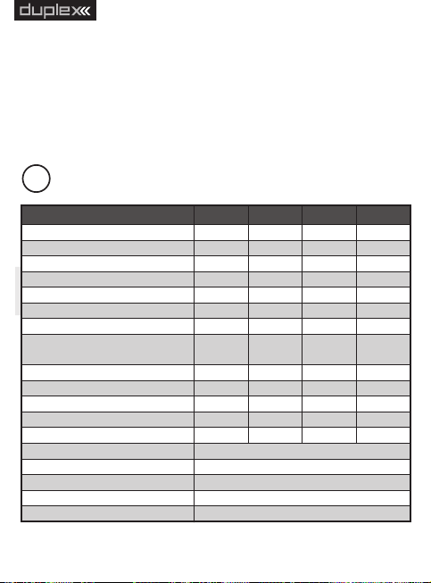
Basic Data
REX6A
REX7A
REX10A
REX12A*
Dimensions [mm]
38x25x11
42x28x11
51x28x11
51x28x11
Weight [g]
111316
24
Antenna length [mm]
2x100
2x200
2x200
2x400
# of channel outputs
6710
12
Temperature range [°C]
-10 to +85
-10 to +85
-10 to +85
-10 to +85
Supply voltage [V]
3.5 – 8.4
3.5 – 8.4
3.5 – 8.4
3.5 – 8.4
Average current [mA]
808080
80
Real time transmission
of telemetry data
Yes
Yes
Yes
Yes
Programming
Tx - DC/DS
Tx - DC/DS
Tx - DC/DS
Tx - DC/DS
Support satellite receiver Rsat
Yes
Yes
Yes
Yes
Power output [dBm]
15
151515
Receiver sensitivity [dBm]
-106
-106
-106
-106
Frequency [MHz]
2400 - 2483
2400 - 2483
2400 - 2483
2400 - 2483
Built-in sensors
3-axis gyroscope, 3-axis accelerometer
Sensitivity of altitude measurement
0,1m
Range of gyroscope measurement
± 2000°/s
Range of accelerometer measurement
± 16G
Gyroscope/accelerometer sampling rate
6600Hz
EN
The JETI model company portfolio contains a diverse offering of
electronic modelling equipment like voltage regulators, motor
speed controllers, telemetry data display equipment, telemetry
sensors and, last but not least, DC/DS transmitters. The JETI
model product manfacturing policy is to constantly produce the
highest quality product possible.
2 Technical data
www.modellmarkt24.ch
www.modellmarkt24.ch
EPC
5
* xternal ower onnector
Page 7

computer radio control system
EN
2.1 Properties
Up to 16 stabilized airplane channels.
Support for different multicopter types – from tricopters to
octocopters.
Up to 3 adjustable flight modes, options for stabilizing the
horizon and altitude.
In-flight gain tuning using free channels.
Using the latest 3-axis gyroscope and 3-axis accelerometer.
Support for LED strip consisting of WS2812 chips.
Support for external camera gimbal driven by servos.
Intelligent fail-safe.
Vibration analysis.
Full set-up options with DC/DS transmitters or via PC.
Available telemetry: Receiver voltage, signal quality, G-force,
attitude orientation.
Support of telemetry and up to 3 sensors connected directly.
2.2 Important Notices
Always use the current firmware in your DC/DS transmitter and
receiver. The minimum version of software for transmitters
supporting REX A receivers is 4.24.
Always check the polarity of the lead wires so that the voltages
on the receiver and other electronics are not reversed.
Do not expose the receiver to heat and sudden temperature
changes that may affect the accuracy of the sensors.
Never use a receiver that is visibly damaged. In particular, check
the state of the antennas regularly. In no way modify or remove
the receiver electronics from the supplied housing.
www.modellmarkt24.ch
www.modellmarkt24.ch
When installing on a combustion engine model, keep in mind
6
Page 8

computer radio control system
that all electronics must be optically isolated from the ignition
unit and ideally located as far as physically possible from the
engine itself.
Do not expose the receiver to excessive vibration. Sensors in the
receiver are very sensitive and vibrations are an undesirable
phenomenon. It is advisable to check the vibration level with the
built-in analyzer before flight and to take appropriate measures
to reduce vibration (e.g. attach the receiver in the model with a
soft double-sided adhesive tape).
Do not expose the receiver to direct air flow. Aerodynamic forces
may have a strong influence on the sensitive barometric sensor
when the model is moving faster.
Always use a sufficiently sized power source for the receiver and
servos. Keep in mind that with the stabilization switched on, the
servos in the airplane model are constantly moving, resulting in
increased current consumption and subsequent heating of the
components.
Any major changes to the settings (especially for the initial
configuration) should be done without the propellers fitted.
During use, it is recommended to switch on the transmitter first
and then the receiver. The transmitter confirms that the receiver
is turned on by an acoustic signal. When turning off the system,
first switch off the receiver and then the transmitter.
REX A receivers do not support Clone mode. This is because the
stabilizing receiver should always be the primary receiver in the
model. Other receivers, serving as satellites, must not have the
stabilization enabled.
www.modellmarkt24.ch
www.modellmarkt24.ch
7
EN
Page 9
computer radio control system
EN
3 Installation
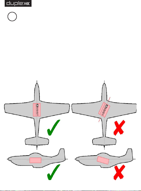
3.1 Installation in the model
Always place the receiver in the model parallel to the flight axes and
ideally as close as possible to the center of gravity (especially for
multicopters). This is important for the proper functioning of
stabilization and its correct response. It is important that the
mounting of the receiver is made in such a way that the vibrations
from the model are minimized and that the fixation is guaranteed at
the right place. We recommend using a double-sided adhesive tape
for this purpose.
www.modellmarkt24.ch
www.modellmarkt24.ch
8
Page 10
computer radio control system
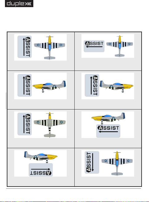
Default - Horizontal
Rotated by 90°
Vertical – on the left
Vertical – on the right
Inverted - Horizontal
Standing – on the left
Standing – on the right
Rotated by 180°
There are several ways to place the receiver in the model, and you
need to activate this position in the setup wizard. The direction of
the arrow on the receiver sticker determines its placement:
www.modellmarkt24.ch
www.modellmarkt24.ch
9
EN
Page 11

computer radio control system
EN
3.2 Power supply
When designing a wiring system in the model, always be careful
about choosing a suitable power supply so that it is sufficiently
current-rated and its output voltage is compatible with the
receiver, servos and other electronics. It is recommended that the
REX A receivers be powered by low-resistance Li-XXX type batteries
or a stabilized BEC voltage source (either as a separate device or
integrated in the speed controller).
Never connect two different voltage sources in parallel, even if
the y seem to have the sa me parame ters. Ins tead, use an
additional circuit, such as DSM10, to separate both sources which
become independent.
The supply voltage can be applied to the receiver in the following
ways:
Via throttle channel (when using the speed controller BEC).
Using any free or open receiver port.
Via the MPX connector included on EPC receivers (Extended Power
Connector).
For multirotors, use either a BEC output from a single controller
or, in case of Opto-type controllers, use an external stabilized
source. Never connect voltages from several BEC circuits in
parallel.
www.modellmarkt24.ch
www.modellmarkt24.ch
10
Page 12

computer radio control system
EN
3.3 Operation
We recommend that you switch on the transmitter first and then
subsequently the receiver. The transmitter confirms the switching-
on of the receiver with an acoustic signal. When switching off the
system we recommend that you switch off the receiver first and
then subsequently proceed with switching-off the transmitter.
3.4 Binding
When using a new receiver or transmitter it is necessary to carry out
the binding process between them. Transmission between the
receiver and transmitter occurs in fully digital manner, therefore it is
necessary to identify and share the addresses of each device
communicating on the mutual 2.4GHz frequency band.
Procedure:
1. Insert the BIND PLUG (included in the receiver packing) into the
receiver socket labeled Ext.
2. Switch on the receiver – (connect a proper voltage supply to the
receiver). Binding of the receiver may now be performed within 60
seconds. After the 60 seconds elapse the receiver returns to setup
mode and the binding process must be repeated by starting again
from step 1.
3. Switch on the transmitter - the transmitter emits an acoustic
signal announcing the detection of a new receiver.
Binding may be carried out with the aid of the JETIBOX instead of
using the BIND PLUG.
www.modellmarkt24.ch
www.modellmarkt24.ch
11
Page 13

computer radio control system
The procedure is as follows:
1. Connect the JETIBOX with the connecting cable to the Ext.
receiver output .
2. Switch on the receiver - (connect a proper voltage supply to the
receiver).
3. The receiver menu appears on the JETIBOX display. Select the
„Pairing“ menu item (push the right arrow button once from the
main receiver display) and then push the upward button. You now
have a period of 60 seconds to bind the receiver. After the 60
seconds elapse the receiver returns to setup mode and the binding
process must be repeated by starting again from step 3.
If the binding process between receiver and transmitter was
unsuccessful, try again.
You may bind an arbitrary number of receivers to one transmitter.
The receiver, however, can only be bound to one transmitter, i. e. the
receiver is only bound to the most recently bound transmitter.
EN
3.5 Range test
By range testing, you verify the correct operation of the transmitter
and receiver. You should perform a range test before your first flight
of each flight day, or if there are any doubts about the function of
the transmitter or receiver. In the range test mode, the transmit
power is reduced to 10%. When testing range, place both the model
and transmitter at a height of at least 80cm (3ft) from the ground. A
properly operating transmitter and receiver should reliably control
the model at a distance of at least 50 meters (or 50 yards) in the test
www.modellmarkt24.ch
www.modellmarkt24.ch
12
Page 14

computer radio control system
mode. If this is not the case, be sure to check the correct installation
of the receiver antennas. If the test is not successful afterwards then
do not use the device and contact your dealer or one of our service
centers.
Setting into Range Test mode:
Insert the pairing jumper (BIND PLUG) into the Ext. port of the
receiver, turn on the receiver and then the transmitter. Range test
mode will be active for as long as the bind plug is inserted in the Ext.
port.
Alternatively, you can run the range test in the DC/DS transmitter
via the System – Servo & Range Test menu.
www.modellmarkt24.ch
www.modellmarkt24.ch
13
EN
Page 15

computer radio control system
EN
4 Quick Setup
4.1 Airplane
From production the REX Assist receivers behave as standard
receivers and stabilization is not active by default. This can be used
to set up an airplane model - the initial procedure is similar:
1. Place the receiver in the model according to the “Installation
in the model” chapter.
2. Create a new model in the transmitter as usual. The individual
channels of the transmitter should correspond with the
outputs on the receiver. If you plan to use additional channels
to tune the stabilization gain or to switch flight modes, this is
the moment you should create them. By doing that you won’t
have to go back to your channel settings while configuring the
receiver via Quick Wizard menu. More information about the
auxiliary channels can be found in the Additional channels
section.
3. Pair the transmitter with the receiver.
4. For the model, set its subtrims, dual rates and expos according
to the recommended values. Do not set up advanced mixes or
change the servo path using servo balancer.
5. Now go to the receiver configuration – either through the
DC/DS menu (Model -> Device Explorer) or via your PC (see
chapter Configuring the Receiver with PC).
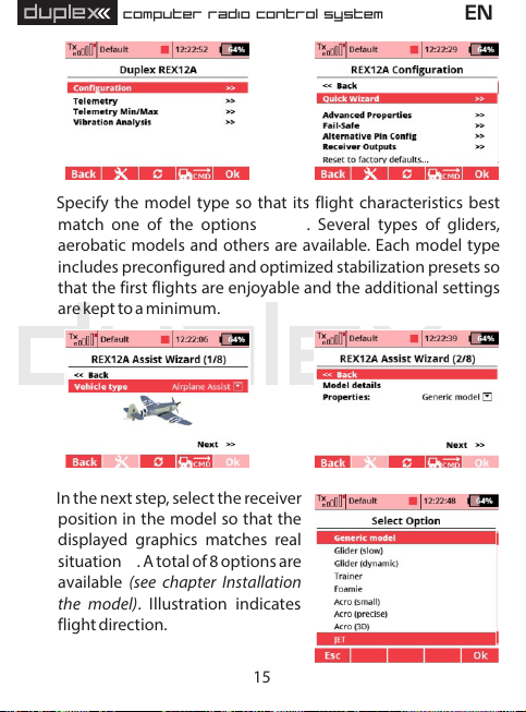
6.b) Run the stabilization setup wizard (Configuration -> Quick
Wizard ) . On the first screen, enter the “Airplane Assist”
www.modellmarkt24.ch
www.modellmarkt24.ch
option and go to the next page with the “Next” link.
a)
c)
14
Page 16
computer radio control system
EN
a)
7. Specify the model type so that its flight characteristics best
match one of the options . Several types of gliders,
aerobatic models and others are available. Each model type
includes preconfigured and optimized stabilization presets so
that the first flights are enjoyable and the additional settings
are kept to a minimum.
c)
8. In the next step, select the receiver
position in the model so that the
displayed graphics matches real
situation. A total of 8 options are
f)
available (see chapter Installation
the model) . Illustration indicates
flight direction.
www.modellmarkt24.ch
www.modellmarkt24.ch
b)
d), e)
d)
e)
15
Page 17
computer radio control system
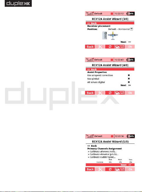
9. Now check for additional features
g):
Use airspeed correction – if the
model is able to move at a large
range of speeds, it is advisable to
supplement it with the MSPEED
sensor or MGPS for measuring
flight speeds. By activating this
field, the receiver will take into
account the current speed while
performing stabilization.
Us e c ame ra gimb al - by
checking, you enable the function
of an external servo control for
camera gimbal.
All servos digital - This option
specifies the servo output period. If all the servos are digital in
the model, the output period will be automatically set to
7.5ms. Otherwise, it will be 17.5ms.
10. Assign the individual channels for stabilization so that the
receiver learns neutral positions
and throws of individual servos .
The model can now be placed
arbitrarily because at this point
you only calibrate the control
functions. Proceed step by step
ac cording to th e wizard a nd
www.modellmarkt24.ch
www.modellmarkt24.ch
calibrate only the axes that will be
f)
g)
h)
h)
16
EN
Page 18
computer radio control system
used during stabilization. Check the correct response to the
controls by looking at values displayed in the “Controls” row. If
the servos in the model are not moving, it is ok at this point -
the receiver will not allow servo outputs until the configurati-
on is completed.
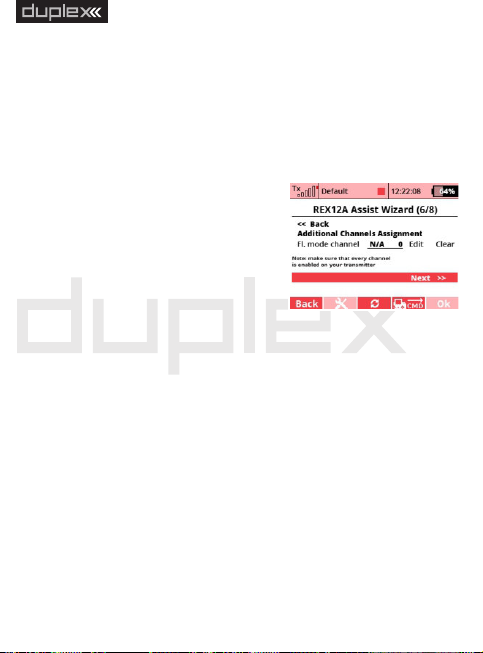
11.f) Assign a channel for switching flight stabilization modes .
This channel should be controlled
by a three- position switch, so that
all three flight modes are available.
In position the stabilization is
disabled by default. Switching to
position (center) activates the
“No rmal” mode. Switching to
position activates the "Heading
Hold" mode.
Note: First add a three-position switch to your DC/DS transmitter
as a new function in the Model – Functions Assignment menu.
Then assign this option to a free channel in the Model – Servo
Assignment menu. Subsequently, this three-position switch can
be used here in the receiver setup wizard.
12. If you have selected the “Use gimbal” option in the previous
steps, assign the individual channels to the gimbal control. You
can skip this point and configure the camera gimbal later in the
Configuration -> Channel Assignment -> Gimbal channels.
www.modellmarkt24.ch
www.modellmarkt24.ch
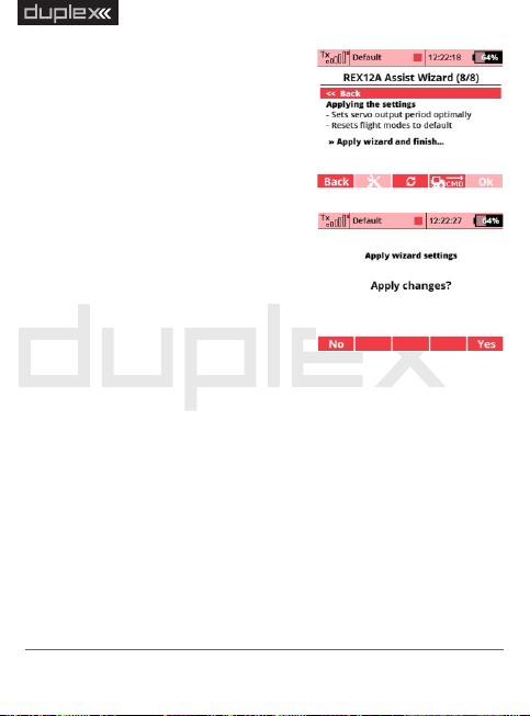
13.j) Finish the wizard and application settings . When you run the
1,
2
3
i)
17
EN
Page 19
computer radio control system
“A p pl y wi z ar d and f in i sh ”
c o mm an d , y o u s t or e th e
parameters in the receiver and the
stabilization is reset to the mode
according to data you’ve entered.
Attention: At this po int , th e
se tt ings of in div id ual se rv o
outputs, flight mode configurati-
on, and the PID control gains will
be reset.
14. Before each flight, place the model
on the ground and hold it stable
during the gyroscope initializati-
on . On ce t he i nitiali zation is
completed, it is possible to move
servos.
15. Check for correct input control response and stabilization
function when moving in each axis. For example, if you rotate
the model to the left, the control surfaces should tend to move
in the opposite direction.
16. Perform the first flight either with stabilization disabled
(manual mode) or in “Normal” mode. If the model does not fly
straight, trim it and then land. Re-assign the primary channels.
Continue to optimize the settings so that the flight characteris-
tics of the model match your preferences.
www.modellmarkt24.ch
www.modellmarkt24.ch
j)
k)
18
EN
Page 20
computer radio control system
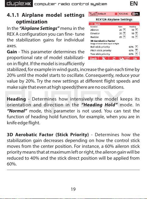
4.1.1 Airplane model settings
optimization
In the “Airplane Settings” menu in the
REX A configuration you can fine- tune
the stabilization gains for individual
axes.
Gain - This parameter determines the
proportional rate of model stabilizati-
on in flight. If the model is insufficiently
stabilized, for example in wind gusts, increase the gain each time by
20% until the model starts to oscillate. Consequently, reduce your
value by 20%. Try the new settings at different flight speeds and
make sure that even at high speeds there are no oscillations.
Heading - Determines how intensively the model keeps its
orientation and direction in the “ Heading Hold ” mode. In
“Normal” mode, this parameter is not used. You can test the
function of heading hold function, for example, when you are in
knife edge flight.
3D Aerobatic Factor (Stick Priority) - Determines how the
stabilization gain decreases depending on how the control stick
moves from the center position. For instance, a 60% aileron stick
priority means that at maximum left or right, the aileron gain will be
reduced to 40% and the stick direct position will be applied from
60%.
www.modellmarkt24.ch
www.modellmarkt24.ch
19
EN
Page 21

computer radio control system
4.1.2 Choice of flight modes
De pen din g on your pr eferenc es,
choose which flight modes to use
during flight - a total of 5 modes are
availab le, allowing you to switch
between three in flight (see Descrip-
tion of flight modes section).
Spe ci fy th e Fail -S af e m od e: In
Intelligent mode, the receiver will
stabilize t he model in horizontal
position. On the other hand, selecting
“Assist Off” will apply preset servos
positions, or the last known position
will be retained (see the Configuration
– Fail-Safe menu for more details).
For each Flight mode, you can set the
default gain (this multiplies the stabilization gain and the heading-
hold ability in all axes). You can also specify whether to use the gain
tuning via special dedicated channels (see Configurati on -
Channel Assignment - Assign Additional Channels).
For each flight mode, it is also possible to specify which servos are
stabilized by which function. By default every combination of
functions is allowed. If you do not need to have e.g. a stabilized
rudder in all flight modes, simply deactivate it in the appropriate
line.
www.modellmarkt24.ch
www.modellmarkt24.ch
20
EN
Page 22

computer radio control system
EN
4.2 Multicopter
Before you connect and configure the REX A receiver for the first
time in a multicopter model, we recommend disconnecting speed
controllers with motors from the receiver to avoid accidental
spinning.
1. Remove the propellers from motors.
2. Place the receiver in the model according to the Installation in
the model chapter.
3. In the transmitter, create a new multicopter model. When
setting up, make sure that Motor/Throttle, A ileron/Ro ll,
Elevator /Pitch, Rudder/Yaw and Flight- Mode switching
functions are operated separately on each channel.
4. Pair the transmitter with the receiver.
5. a) Navigate to the receiver settings either via the DC/DS menu
(Model -> Device Explorer) or via USB adapter and JETI Studio.
6. b) Run the stabilization setup wizard (Configuration -> Quick
Wizard). On the first screen, enter the “Multicopter Assist”
option.
a)
www.modellmarkt24.ch
www.modellmarkt24.ch
b)
21
Page 23

computer radio control system
Tricopter Y
Quadcopter +
Quadcopter X
Hexacopter +
Hexacopter X
Hexacopter Y
Octocopter + (REX10 A or
REX12A)
Octocopter X
(REX10 A or REX12 A)
7.c) d) Select the type of your multicopter frame and continue to
the next page by pressing the “Next” link. The following types
of frames are supported (direction of rotation and motor
sequence must always be observed):
www.modellmarkt24.ch
www.modellmarkt24.ch
22
EN
Page 24

computer radio control system
EN
c)
8.e) On the next screen , select the
multicopter characteristics to best
match your model. Each type
inc ludes preco nfig ur ed and
optimized presets for stabilization
so that th e f ir st fl ights ar e
enj oy ab le an d a dd ition al
settings are kept to a minimum.
9.f) In the next step , select the
receiver position in the model so
tha t the d is play ed gr aphic s
matches real situation. A total of 8
options are available (see chapter
Installation in the model). The
illust ration ind icates fli ght
direction.
10.g) Now check for additional features :
Use camera gimbal - by checking this option, you enable
the function of the external servo-controlled camera gimbal.
www.modellmarkt24.ch
www.modellmarkt24.ch
All servos digital - This option specifies the output period
d)
e)
f)
23
Page 25

computer radio control system
fo r s er vos th at are use d a s
additional channels. If all the
servos in the model are digital, the
output period will be automati-
cally set to 7.5ms. Otherwise, it
will be 17.5ms. The output
control period for the motors is
2.5 ms, which means 400Hz.
Use OneShot125 - by checking this option, you enable the
OneShot125 mode to control the multicopter speed
controllers. This is a special mode where the pulses from the
receiver are eight times shorter than the standard servo
pulses. OneShot125 must also be supported on the controllers
side.
Always stabilize motors - after activating this option, the
multicopter will be stabilized from the moment of arming and
the first throttle application until switching off the motors.
Stabilization will always work, even with throttle at idle
position. This option is not recommended for first flights with a
multicopter.
11. Assign the individual channels for
stabilization so that the receiver
le arns neutr al po sit ions and
channel throws . Follow the step
by step guide. Calibrate all
axes sequentially one by one.
Check correct responses to the
controls by the values displayed in the “Controls” row.
www.modellmarkt24.ch
www.modellmarkt24.ch
h)
g)
h)
24
EN
Page 26

computer radio control system
12. Assign a channel for switching flight stabilization modes. This
channel should be operated by a three- position switch, so
that all three flight modes should be available. In position 1
the altitude and horizon stabilization is enabled by default.
Switching to position 2 (center), a
simple horizon stabilization mode
with direct throttle is activated.
Switching to position 3 activates
the aerobatics mode.
Assign the throttle channel. Make
sure this channel on t he
indicator works in the range 0-
100% (1-2ms).
13. If you have selected “Use gimbal”
in the previous steps, assign the
individual channels to control it
j). You can skip this point and
configure the camera gimbal
later in the menu Configuration -
> Channel Assignment –> Assign
gimbal channels.
i)
j)
EN
14. Finish the wizard and application
k)
settings . After executing the
“Ap ply w iza rd an d fin ish”
command, the parameters in the receiver are stored and the
stabilization is reset to the mode according to the data you’ve
www.modellmarkt24.ch
www.modellmarkt24.ch
entered.
k)
25
Page 27

computer radio control system
Attention:
At this point, the settings for individual motors/servo outputs,
flight mode configurations and PID control gains will be reset.
15. In the Configuration -> Multicopter Settings menu, test the
correct rotation direction of the motors according to the
diagram displayed on the top of the screen.
16. Now lay the model on a flat surface - once the stabilization is
initialized, the speed controllers usually respond by beeping.
Try arming the motors (still without the propellers attached):
With the throttle at idle position, move the two sticks to the
extreme positions (the elevator fully up and the ailerons with
the rudder towards each another):
Motors should start spinning and after 3 seconds without
applying throttle they should stop. If the motors are not
spinning, check the “Minimum running throttle” parameter
in the Configuration -> Multicopter Settings menu.
www.modellmarkt24.ch
www.modellmarkt24.ch
26
EN
Page 28

computer radio control system
17. Before your first flight, it is necessary to test the stabilization
reaction with the propellers, ideally when the model is
mounted on a test bench which allows rotation in only one
axis. It is necessary to ensure that the model in the Aerobatic or
Sport mode is able to maintain a constant direction at zero
stick movement and also to avoid undesirable oscillations.
18. Make your first flight in calm air on a grassy or other soft surface
with plenty of space. Start by arming the motors and lightly
adding throttle. Use small stick movements to make sure that
the receiver responds in correct direction of each axis and tries
to stabilize the model. If you experience any unexpected
behavior, be prepared to immediately lower the throttle and
land. Continue flying in one place and at low altitude - if the
flight is unstable or oscillation occurs in any axis, land and
adjust the gain of the PID control loop (see the next chapter).
Retest the new setting again in flight.
4.2.1 Optimize multicopter settings
Before your first flight with a multicopter model, always test the
rotation direction of the individual motors. In the receiver
configuration, go to the Multicopter Settings menu. Here, choose a
minimum value for running throttle to make the motors slowly spin
when the multicpoter is armed.
Set parameters Throttle Off and Maximum throttle according to
the recommended setting from the manufacturer of your ESC.
Test the rotation direction of each motor by activating the
www.modellmarkt24.ch
www.modellmarkt24.ch
command “Test motor N”. The corresponding speed controller
27
EN
Page 29

computer radio control system
recei ves a command to run at
minimum revolutions for approximate-
ly 1s. The rotation direction must
correspond to the diagram in the menu
on the transmitter display. If the motor
rotates in the opposite direction, swap
any two motor leads between each
other.
Overwrite all motors - you can enter
any value from 0.8 to 2.2ms, which is
sent to all motors at the same time after
the F4 “A pp ly ” bu tt on on the
transmitter is pressed.
Use OneShot125 - Check this option
to enable OneShot125 mode for controlling the multicopter speed
controllers. This is a special mode where the pulses from the
receiver a re 8 times shorter than standard servo pulses.
OneShot125 must also be supported by the speed controllers in
your model.
Always stabilize motors - after activating this option, the
multicopter will be stabilized from the moment of arming and
applying the throttle for the first time until the model is disarmed,
which means the motors are switched off. Stabilization will always
work even with the throttle at idle position. This option is not
recommended for first flights with your multicopter.
www.modellmarkt24.ch
www.modellmarkt24.ch
28
EN
Page 30

computer radio control system
If the multicopter is capable of flying,
but its behavior is not entirely ideal, it
will be necessary to fine-tune the PID
gains of the stabilization loop - see the
C o n f i g ur a t io n - > A d va n c e d
Properties menu. Here you can edit
individual coefficients for each axis
separately.
Proportional coefficient – this is a basic parameter of stabilization.
The response of the control unit is directly proportional to the
desired rotation speed. If the multicopter is not sufficiently
stabilized in some axis, e.g. the pilot must always interfere with the
steering to keep the model in the air, increase this factor (at each
step, for example, by 20%). Once the oscillation starts, reduce the
proportional factor by 20%.
Integral coefficient - determines the weight of stabilization error
accumulated from the past. Thanks to integrating, the receiver is
able to return the model to its original orientation, even if it has
been previously displaced. Set this factor so that the model does
not tilt in the air in any axis and keeps a steady attitude in the Sport
or Acrobatic mode. If the coefficient is too high, slow but strong
oscillations might appear.
Derivative coefficient - The derivative component of the
stabilization loop responds to rapid changes in model orientation
and is able to suppress, for example, the effects of wind gusts. Edit
the value of the derivative component very carefully with small
www.modellmarkt24.ch
www.modellmarkt24.ch
29
EN
Page 31

computer radio control system
steps, as the model might begin to oscillate very quickly.
When testing the modified coefficients, take off and apply small but
fast movements on the inputs and check if the multicopter reacts
quickly, but without overshots. The rudder axis (Yaw) is not so
critical for fine tuning the gain - after moving a stick in yaw
direction, the multicopter should not become unstable and should
not experience significant changes in altitude. Leave the derivative
coefficient at zero.
For multicopter models, the altitude and climb/descent stabilizati-
on can also be tuned. If the model responds more violently than
expec ted to the climb comman d, lower the proport ional
coefficient in the appropriate row (Vertical Speed). Conversely, if it
does not respond to the altitude change at all, increase the
coefficient value.
4.2.2 Choice of flight modes
De pen din g on you r prefere nces,
choose which flight modes to use
during flight - a total of 5 are available,
switching between three is available
(see the Description of flight modes
section).
For each flight mode, you can set the default gain (this multiplies
the proportional, integral and derivative coefficients in all axes),
and you can specify whether you want to use gain tuning via special
www.modellmarkt24.ch
www.modellmarkt24.ch
30
EN
Page 32

computer radio control system
chan nels (see C onf igu rat ion -> Chan nel Assignme nt ->
Additional Channels Assignment).
Determine the fail-safe mode:
In intelligent mode, the receiver will stabilize the model horizon (at
the last known throttle level). On the other hand, when selecting
“Assist Off”, all engines will be stopped.
EN
4.3 Description of flight modes
In the REX Assist receiver, you can switch between several flight
modes, with the 3 default ones being preset. The default flight
modes can be replaced by any combination of the following
modes:
4.3.1 Manual (Assist Off): Airplanes
The basic airplane mode where the stabilization function is
completely deactivated and the pilot takes over the manual
control.
4.3.2 Training: Airplanes
This mode is used by the pilot to get accustomed to the model's
behavior, and is also useful for beginners. Basically the stabilization
does not interfere with the steering when the model flies
horizontally. However, as soon as you want to make a maneuver, the
stabilization will not allow you to exceed the maximum safe angles
for tilting the aileron axis or the elevator. Aerobatics in this mode is
www.modellmarkt24.ch
www.modellmarkt24.ch
not possible.
31
Page 33

computer radio control system
4.3.3 Normal (Damping): Airplanes
This is a basic mode for flying in the wind, suitable for takeoffs and
landings. Stabilization works in 3 axes and suppresses the effects of
external forces like wind turbulences or gusts. Aerobatics may be
unlimited. In this mode, you can use trims even for stabilized axes.
4.3.4 Heading Hold: Airplanes
A mode designed for those aerobatic figures where it is necessary
to maintain the constant flight direction. These include, for
example, hovering or knife edge flight. Do not use the Heading
Hold mode at takeoffs or landings, as there may be a risk of stalling
at low speeds and the stabilization would increase the effect even
more, which could lead to a crash. Do not use trims in this mode,
because any shift of the center position will be perceived as an
instruction to start rotation.
For gliders, do not use Heading Hold mode if the model is moving
at or near stall speeds (typically when sailing in thermals). The
model stops being sensitive to climbing currents, and then
dropping and falling may occur because the stabilization
correction is not able to fully return the model to its original
orientation with the only function of control surfaces.
4.3.5 Stabilization of the horizon: Airplanes and
Multicopters
Stabilization of the horizon is also suitable for beginners. In this
case, the stabilization algorithm makes it possible to perform basic
aerobatics, but if the pilot leaves the controls in the center position,
www.modellmarkt24.ch
www.modellmarkt24.ch
the model is leveled to horizontal flight. For airplane models, keep
32
EN
Page 34

computer radio control system
in mind that it is necessary to maintain sufficient speed, as the
Heading Hold mode is active at the same time.
4.3.6 Stabilize: Multicopters
The basic functions of the RE X A receiver to stabilize the
multicopter. The model is kept in a horizontal position during the
flight, with the position of the controls indicating the pitch and roll
angle of the multicopter. Maximum tilt angles can be defined in the
Configuration - Advanced Properties menu, by default it is set to
±45°. In this mode, altitude stabilization is not active, and there is no
possibility of aerobatics.
4.3.7 Sport: Multicopters
This mode allows basic aerobatics even for multicopters, since the
receiver only stabilizes the rotation speeds in individual axes and
does not level the model to the horizontal flight. Altitude
stabilization is also deactivated. The transmitter sticks control the
rotation speed of each axis, the maximum speed can be defined in
the Co nfigu ratio n - Ad vance d P rope rt ie s menu (M ax .
roll/pitch/yaw rate).
4.3.8 Acro: Multicopters
This mode is similar to the Sport mode, additionally with direct stick
input applied (adjustable in Configuration - Advanced Properties
- Aerobatics Factor/Stick Priority). E.g. The 60% aileron stick
priority means that at maximum left or right stick position, the
aileron stabilization gain will be reduced to 60%, and from 40% the
direct stick position will be applied.
www.modellmarkt24.ch
www.modellmarkt24.ch
33
EN
Page 35

computer radio control system
Default flight mode configuration for airplanes
Position 1
Position 2
Position 3
Manual
(stabilization off)
Normal stabilization
mode
Heading Hold
Default flight mode configuration for multicopters
Altitude and horizon
stabilization
Horizon stabilization
Sport
EN
4.3.9 Altitude stabilization: Multicopters
This mode is similar to the Stabilize mode, with the climb and
descent rate being stabilized. The throttle position indicates
vertical velocity. In the neutral position of the stick (which is around
1.5ms), constant altitude is stabilized. By adding the throttle, the
model starts to climb.
Caution:
If you completely pull the throttle to idle position to reach the
maximum descent speed, keep in mind that if you do not use
Al ways sta bili ze moto rs op tion , the stab iliz atio n wil l be
co mple tel y d eact iva te d and th e mod el ma y c ras h. We
recommend not fully pulling the throttle when descending, or
shifting the throttle curve on your transmitter.
www.modellmarkt24.ch
www.modellmarkt24.ch
34
Page 36

computer radio control system
EN
5 Additional stabilization features
Additional functions of the REX A receivers can be used to fine tune
or extend the basic stabilization functionality.
5.1 Throttle to PID attenuation (TPA)
This feature is available for multicopter models to help suppress
oscillations when throttle is pushed rapidly. If the model flies well
with low throttle, but begins fast oscillations when adding throttle,
set “T PA bre ak po int” and “T PA val ue” in th e m enu
Configuration -> Advanced Properties. Set the breakpoint below
the level at which the oscillations begin and gradually increase the
TPA value in increments of 10%, until the flight is comfortable even
with full throttle.
Example of TPA setting in a graph: “TPA breakpoint” = 50%,
“TPA value (PID reduction)” = 50%. If you set more than 50%
throttle, the stabilization gain will begin to decrease to a final 50%
at full throttle.
www.modellmarkt24.ch
www.modellmarkt24.ch
35
Page 37

computer radio control system
EN
5.2 Airspeed compensation
This feature is available for airplane models and helps to suppress
oscillations in stabilized flight at high speeds. As the control
surfaces efficiency increases at the same time as the speed
increases, the stabilization gain in the individual axes should be
adjusted accordingly with respect to the actual speed so that the
resulting stabilization effect is constant throughout the flight and
there are no inappropriate reactions.
The airspeed compensation function can be comfortably used in
turbine models that are able to move at a high range of speeds. To
determine the speed compensation correctly, the model must be
equipped with the MSpeed EX sensor (measuring airspeed) or
MGPS EX (measuring absolute speed with respect to the Earth's
surface). We recommend using an airspeed sensor, which is
important for the model's behavior and flight characteristics, for
example at stall speeds. The MGPS sensor is simpler to install, but
this sensor does not take into account the wind speed, so that the
function of compensation won’t be accurate in strong wind and at
low speeds.
Airspeed compensation setting: In the Receiver Configuration,
you will see the “Advanced Properties” menu and the “Speed-
PID Attenuation” section. Set the “Optimize for speed”
parameter to a usual flight speed, where no oscillations occur. From
this speed, the stabilization gain will be gradually reduced.
5.3 Additional channels
To assign additional channels, locate Configuration -> Channel
www.modellmarkt24.ch
www.modellmarkt24.ch
Assignment -> Assign Additional Channels. For proper operation,
36
Page 38

computer radio control system
each channel must first be created on the transmitter – when using
DC/DS transmitter via the Model menu -> Function Assignment
and Servo Assignment.
Flight mode switching channel - here you can assign a
dedicated channel to switch flight modes. This channel should
ideally be operated by a three-way switch on the transmitter.
Throttle channel - is important for multicopter models. A
proportional throttle control channel will be shown here.
Fail-Safe channel - Here you can assign a dedicated channel
operated by a two-position switch that, after switching to the active
position, will simulate the signal loss event. The servos will move to
their predefined positions afterwards.
Assist-Off channel - Here you can assign a dedicated channel
operated by a two-position switch, which, when switched to the
active position, forces the stabilization to switch off (i.e. the airplane
model will enter the manual control mode while the multicopter
stops the motors immediately).
G a i n t u ni n g c h an n e l s :
Ailerons/Roll, Elevator/Pitch
a nd R ud d er / Yaw - a ss ig n
proportional channels controlling
stabilization gains in each axis if
needed. Positive value increase up to
www.modellmarkt24.ch
www.modellmarkt24.ch
do ubl e the defau lt g ain , while
37
EN
Page 39

computer radio control system
negative percent values decrease to a minimum of 10%. The value
of 0% corresponds to the unchanged default gain value.
EN
5.4 Camera gimbal
REX A receivers support the connection of up to three-axis camera
gimbal, whose individual axis (roll, tilt
and pan) are controlled by ser vos
connected to individual channels. If
you plan to use this feature, activate it
in the Assist Setup Wizard, click “Use
gi mb al”. You can c onfi gure the
individual outputs for the gimbal
servos either by going through the
wizard (step 7) or in the Configuration -> Channel assignment
menu - >Gimbal channels:
Gimbal Roll - Shows the channel assigned in the transmitter to tilt
the camera to the left and right. The same channel will be used on
the receiver side for the output of the given camera gimbal axis.
Maximum roll - Specifies the angle at which the tilt servo is at its
maximum displacement. Set this value so that the image stays
stable when moving the model and does not tilt left or right.
Gimbal Pitch - Shows the channel assigned in the transmitter to
tilt the camera up and down. The same channel will be used on the
receiver side to output the given camera gimbal axis.
www.modellmarkt24.ch
www.modellmarkt24.ch
38
Page 40

computer radio control system
Maximum pitch - Specifies the angle at which the servo is tilted
to its maximum deflection. Set this value so that the image is stable
when moving the model and does not tilt up or down.
Camera Yaw (pan) - Shows the assigned channel on the
transmitter to rotate the camera. The same channel will be used on
the receiver side to output the given camera gimbal axis.
Maximum yaw - Specifies the angle at which the servo is rotated
to its maximum deflection at maximum damping. Set this value so
that the image is stable when the model moves and does not rotate.
Damping (dmp.) - Damping factor in the rotation axis. The
higher the value, the longer the camera will stay in the original
direction, and it will take longer time for it to turn to the new
direction. At 100% the gimbal will always try to keep the original
orientation.
EN
5.5 Connecting an external LED strip
The REX A receivers support the connection of an external LED strip
consisting of up to 32 programmable
RGB LEDs of the WS2812 type. A single
receiver port is dedicated to the strip,
which must first be configured to
enable the strip. In the Configuration
–> Al tern ative P in C onfi gura tion
menu, select the dedicated output pin
www.modellmarkt24.ch
www.modellmarkt24.ch
39
Page 41

computer radio control system
Off
The LED is off
Arming State
The color indicates the “Armed” and “Disarmed”
states.
Flight Mode
The color indicates the active mode from three
possible.
Roll Left
Blinking in orange indicates the tilt in the aileron
axis to the left.
Roll Right
Blinking in orange indicates the tilt in the aileron
axis to the right.
Color
The following are available: white, red, orange,
yellow, lime green, green, mint green, cyan, light
blue, blue, dark violet, magenta, deep pink.
and switch it to “LED Strip” configurati-
on. The “LED Strip Settings” link then
appears in the receiver configuration,
allowing you to change the colors and
functions of the individual LED chips.
The connection of LED strip itself is simple, you can connect the
three-core cable terminated with the JR connector on the input
side of the strip (with the pad marked Din). This connector is then
plugged into a dedicated port in the receiver.
www.modellmarkt24.ch
www.modellmarkt24.ch
40
EN
Page 42

computer radio control system
EN
5.6 Sensor data filtering
REX A receivers embed advanced digital algorithms for filtering
sensor data. The algorithms are designed to suppress undesirable
effects caused by vibrations in the model. Two types of filters are
used:
Low Pass Filter - This type of filter transfers frequencies below
the set limit and all higher frequencies are suppressed. Its basic task
is to separate the desired data containing changes in model
attitude (low frequency) from unwanted vibrations (high
frequencies).
Band Filter (Notch Filter) – It’s used to filter out specific
frequencies caused by engine vibrations. You can additionally
activate this filter if the vibrations caused by the engine are
relatively high. Check the vibration level regularly via “Vibration
Analysis” receiver menu with the engine running. The engine
should run at such revolutions as are most common in flight.
Example of band filter adjustment:
The illustration shows vibrations of a
motor that rotates at 200Hz, 12000
rpm. We will choose the average filter
frequency of 200Hz, as there is a peak in
this area. We set the filter bandwidth
somewhere between 50-150Hz. The
narrower the filter bandwidth, the
www.modellmarkt24.ch
www.modellmarkt24.ch
more precisely the filter will be able to reduce the signals with the
41
Page 43

computer radio control system
specified frequency. However, as the motor speed and thus the
vibration frequency changes during flight, it is preferable to choose
wider bandwidth, approx about 100Hz.
Set both types of filters in the Configuration -> Advanced
Properties and the Filtering section.
EN
5.7 Sensor calibration
Sensor calibration is important for the
correct and accurate func tion of
stabilization. The receiver calibrates
the offsets of an internal gyroscope
automatically, always after the receiver
is switched on. Approximately for 2
seconds after turning on, keep the
model at stationary position. It’s not
required to keep the model horizontally, but the tilt angle should
not exceed 30°. Once the gyroscope is calibrated, the stabilization is
armed and ready for flight.
The internal barometer is being calibrated at the same time as the
gyroscope to create a reference zero level for calculating the
relative altitude.
Calibration of the accelerometer is a more complex process. The
receiver is already calibrated from the factory, but due to the Earth's
gravitational field, which is not constant all over the planet, the
accelerometer can show inaccurate measurements. We recom-
www.modellmarkt24.ch
www.modellmarkt24.ch
mend you to calibrate the accelerometer also when you configure
42
Page 44

computer radio control system
the receiver in a new model for the first time:
In the receiver menu, view Telemetry -> Sensor Calibration screen.
Activate the “Start calibration” command and follow the
instructions. The receiver must be placed on a horizontal board
with one of its six sides and kept still for about 2 seconds. Once the
position is correctly recorded, the “Remaining positions” line is
decremented - at this time rotate the receiver and place it on the
board by another side. Repeat until the number of remaining
positions is greater than zero.
After completing the calibration, please make sure that the total G-
Force displayed on the Telemetry screen lies in the range of 0.99 -
1.01G (measured at rest).
EN
5.8 Vibration analysis
Vib ra ti on s are an u nd es ir ab le
phenomenon for any stabilization
system, as it adds unwanted noise into
measurement. In the receiver menu,
you can display a graph showing the
actual vibration level. It’s measured
using frequenc y ana lysi s in the
selected accelerometer axis.
The receiver itself contains effective algorithms to suppress the
vibrations (see Configuration -> Advanced Properties), but the
www.modellmarkt24.ch
www.modellmarkt24.ch
cost is a relative reduction of the model's preciseness and
43
Page 45

computer radio control system
maneuverability.
If the vibrations are too high (in the graph approximately over the
half of Y axis), we recommend taking some of the following
precautions to reduce them:
Fix the receiver in the model with a soft double-sided adhesive
tape.
Secure the cables leading to the receiver so they cannot move
arbitrarily in the model which could amplify the vibrations.
Use a balanced propeller.
www.modellmarkt24.ch
www.modellmarkt24.ch
44
EN
Page 46

computer radio control system
EN
6 Advanced properties
Output period - setting the output signal period (Auto setting can
be used to synchronize outputs with the transmitter). This
parameter fundamentally affects the behavior of the servos.
Setting lower output period leads the analogue servos to achieve
faster response and increases current consumption. Some types of
analogue servos may behave erratically if the value is set too low.
Number of PPM channels - Set the number of channels
encapsulated in the PPM serial stream. If the receiver gets fewer
channels than this setting, the remaining channels (in the
Computed mode) will be replaced by a default value specified in
the Fail-Safe position for each channel. Otherwise, the number of
output channels will be reduced to the set value.
PPM/UDI Mode - Defines how the transmitter data is processed.
You can choose from the following modes:
Direct - The PPM and UDI output signal contains data directly
- Conversions and eventual channel mapping are only
- Various settings for servo outputs and for PPM/UDI
Computed - Both servo outputs and PPM or UDI signals are
- Output pulses for servos and PPM/UDI contain the
www.modellmarkt24.ch
www.modellmarkt24.ch
from the transmitter without any recalculation.
applied to servo outputs.
can be set.
recalculated and mapped.
same information, but neither PPM nor UDI carries
flight-stabilized data.
45
Page 47

computer radio control system
Note: This option does not apply to EX Bus outputs. These are
always direct without receiver recalculation (if the function
"Stabilize EX Bus output" is not activated).
Stabilize EX Bus output - Check this option to ensure that flight
stabilization is applied to the EX Bus output. In such case, the serial
data will correspond directly to servo outputs. This mode is useful if
you are planning to use the REX A receiver with stabilization
enabled along with a Central Box 100/200/400.
Low Voltage Alarm - Used to set the decision level of the low
voltage alarm, which is indicated by the receiver itself. You can also
set the low voltage alarm directly in the DC/DS transmitter (Timers /
Sensors -> Alarms menu).
EN
6.1 PID control setting
Aileron/Roll rate, Elevator/Pitch rate, Rudder/Yaw rate - In this
section you set the individual PID control coefficients for each axis
separately for multicopter models. These coefficients are applied in
all flight modes to stabilize the rotational speed around each axis.
Vertical Speed - PID coefficients to stabilize the climb and descent
rate.
Aileron/Roll angle, Elevator/Pitch angle, Rudder/Yaw angle -
Here you can change the proportional gain of attitude stabilization,
e.g. horizon. The higher the coefficients you specify, the faster the
www.modellmarkt24.ch
www.modellmarkt24.ch
model is reoriented to the new attitude.
46
Page 48

computer radio control system
EN
6.2 “Stabilize” mode setting
Maximum roll angle - Defines the maximum possible tilt angle to
the left and right in the horizon stabilization mode (controlled by
aileron input).
Maximum pitch angle - Definition of the maximum possible tilt
angle in horizon stabilization mode (controlled by elevator input).
Minimum pitch angle - Definition of the minimum possible tilt
angle in horizon stabilization mode (controlled by elevator input).
PID transition delay - Used to switch between flight modes that
use stabilization with different gains of the PID coefficients. This
feature guarantees that the change of the coefficients does not
cause erratic behavior in flight.
Sensor trim (Roll/Pitch) – Using these parameters you can fine-
tune the receiver position in the model if its position is not
absolutely parallel to the axis of ailerons and the elevator. Sensor
trims are applied in the flight modes where the horizon is stabilized
and you can achieve, for example, with airplane models a slightly
pulled horizontal flight.
Quick trim setting: Place the model on a flat solid horizontal
surface so that its position exactly matches the horizontal flight (a
multicopter should be positioned exactly horizontally). Now in the
Receiver Configuration -> Advanced Settings -> activate the “Set
sensor trims now” command. The calculated values will be stored
www.modellmarkt24.ch
www.modellmarkt24.ch
in receiver memory.
47
Page 49

computer radio control system
EN
6.3 Acro mode settings
Maximum Aileron/Roll rate, Maximum Elevator/Pitch rate,
Maximum Rudder/Yaw rate - Specifies the maximum angular
rotation speed in individual axes (in degrees per second) that can
be safely reached by the model. For acrobatic models, this value can
be up to two revolutions per second (720°/s), but for gliders it will
be noticeably smaller (e.g. 90°/s).
Aerobatics Factor (Roll/Pitch/Yaw stick priority) - Determines
how the stabilization gain will be decreases depending on how the
control stick moves away from the center position. For example, a
60% aileron stick priority means that at maximum left or right stick
position, the aileron gain will be reduced to 60% and the direct
position of the stick will be applied from 40%.
Throttle-PID Attenuation (TPA) – A function for multicopter
models, see Chapter 10, “Other stabilization features”.
Speed-PID Attenuation – A function for airplane models, see
Chapter 10, “Other Stabilization Functions”.
Dead Zone
Dead zone parameters indicate the size of the area around the
center position of the controls, where the resulting stick position in
the given direction is considered zero.
www.modellmarkt24.ch
www.modellmarkt24.ch
48
Page 50

computer radio control system
EN
6.4 Filtering
Low-Pass filter frequency - Here you enter the frequency of the
digital filter (in Herz units) to suppress vibration noise on the
gyroscope. Keep in mind that the lower the frequency you enter,
the less the model will be prone to vibration, but the accuracy and
speed of flight stabilization will be limited. The recommended
value is 10-20Hz for airplanes and 20-60Hz for multicopters.
PID Derivative Low-Pass filter - Here you enter the frequency of
the digital filter (in Herz units) to suppress noise of the derivative
component of the stabilization control loop. Recommended value
of 20Hz should be modified with caution.
Filter specific frequency - By enabling this option, you enable
advanced filtering to remove specific vibrations caused by motor
running. Adjust the average filter frequency and filter bandwidth
according to the vibration analysis graph.
Arming switch
The arming procedure is automatic for airplane models so that the
stabilization is enabled automatically after receiver initialization.
On the contrary, for multicopters, you must move the controls to
the extreme positions when the throttle is pulled low for arming.
Alternatively, you can assign a two-position switch on the DC/DS
transmitter to arm the stabilization and make the propellers spin.
This switch does not need to be assigned to any channel on the
transmitter - the arming command is sent separately as soon as you
confirm the dialog box that appears after activating the switch.
www.modellmarkt24.ch
www.modellmarkt24.ch
49
Page 51

computer radio control system
EN
6.5 Fail-Safe
Fail-Safe – Turns the Fail Safe function
on or off. If the function is disabled, no
pulses on the receiver outputs are
generated in case of signal loss. If this
func tion i s enabled, the receiver
outputs can be configured individually
with the following options:
Hold - The receiver repeats the last known values on its output.
Out OFF - the output pin is deactivated.
Fail-Safe - the output is moved to a position given by the
parameter “Value” at a speed given by “Speed” parameter. You
can set the Fail-Safe positions either by editing each output
value separately or by simply moving the transmitter controls to
the required position and activating the “Set fail-safe position
now” command.
Fail-Safe Delay – Indicates the time interval from a moment the
receiver detects signal loss to when the fail-safe control throws are
initiated. After the expiration of this time, the receiver outputs will
transfer to preset defaults or will be turned off (according to
individual pin settings).
www.modellmarkt24.ch
www.modellmarkt24.ch
50
Page 52

computer radio control system
EN
7 Alternative pins configuration
Here you can change the modes of the
receiver pins. Servo outputs can be
configured, for example, in digital
input or digital output mode.
Servo - standard impulse output for
servo control (-100% ~ 1ms, 0% ~
1.5ms, + 100% ~ 2ms).
If the output pin is set to "Servo" mode, you can specify maximum
possible throws that will never be exceeded. These limits should be
adjusted to protect individual servos against overshots and model
damage.
Digital input - the logic value of a given signal pin (0 or 1) is
transferred to the transmitter in the form of EX telemetry (so it can
be further displayed and stored). Receiver pins are equipped with
internal pull-up resistors, so you can easily connect the signal wire
to the ground for logic level detection. It is not allowed to connect
external voltage to this pin.
Digital output - the receiver will discretize the channel value of the
given pin. If this value is greater than 1.5ms (>0%), the output pin
value will be logic “1”. Otherwise, the output value will be logic “0”.
Using this approach, you can control e.g. simple model lighting
made up of LEDs. In this mode, the Fail-Safe settings for the pin are
also applied.
www.modellmarkt24.ch
www.modellmarkt24.ch
51
Page 53

computer radio control system
Motor 1-8 - for a multicopter model, this parameter is used to
identify individual motors (assignment is made automatically via
the Quick Wizard). Refresh rate of the motor outputs is 400Hz by
default, and conventional servo pulses or OneShot125 protocol can
be used for control.
Camera control (roll, tilting/pitch, and pan/yaw) - output pins
assignment for a stabilized camera gimbal controlled by servos.
PPM Positive Output - standard PPM signal with positive logic of
the PPM data stream. The idle state of the line is logic 0.
PPM Negative Output - standard PPM signal with inverse logic of
the PPM data stream. The idle state of the line is logic 1.
PPM Input - For a given receiver port, the PPM input signal from
another receiver is expected. This option is suitable if you want to
use a backup receiver with a PPM output stream.
JETIBOX/Sensor EX - connection of telemetry sensor or JETIBOX.
EX Bus - digital bidirectional communication for channels
transmission, telemetry and communication data. This setting is
suitable for example in connection with a Central Box or other EX
Bus-capable device.
Serial UDI12/16 - serial output suitable for connection of devices
with UDI support (Universal Data Interface, e.g. Vbar).
www.modellmarkt24.ch
www.modellmarkt24.ch
52
EN
Page 54

computer radio control system
REX 6A
REX 7A
REX 10A
REX 12A
Pin1
Y1Y1Y1
Y1
Pin2Y2Y2Y2Y2
Pin3
Y3Y3Y3
Y3
Pin4Y4Y4Y4Y4
Pin5
Y5/E1
Y5, LED Strip
Y5, LED Strip
Y5
Pin6
Y6/E2
Y6/E1Y6Y6
Pin7
Ext.
Y7/E2
Y7
Y7
Pin8
Ext.
Y8/E2
Y8/E2
Pin9 Y9 Y9
Pin10
Y10
Y10
Pin11
Bat.
Y11
Pin12
Bat.
Y12, LED Strip
Pin13
E1
E1
Pin14
Ext.
Ext.
LED Strip - A LED strip composed of programmable LED chips can
be connected to the dedicated pin of the receiver.
Table of possible functions on the individual receiver pins
Output types:
Y - servo output, digital output, digital input, motor 1-8 (multicopters),
camera roll, pitch, and yaw.
E1,2 - JETIB OX/EX sensor, PPM output, PPM input, EX Bus output, UDI
output
Ext. - JETI BOX/EX sensor
www.modellmarkt24.ch
www.modellmarkt24.ch
53
EN
Page 55

computer radio control system
EN
7.1 Receiver Outputs
The receiver output settings screen allows you to redirect the
transmitter channels to any receiver output. For clarity, the
transmitter channels are described by their numerical value and
their meaning.
As the last parameter, you can set the output group (A-H) for each
servo separately. Assigning servo outputs to the same group means
that their control pulses will be generated at the same time. For the
100Hz mode, we recommend using only A-C groups. In addition,
please note that the servos belonging to the same function should
be ideally in the same group.
Note:
Channel redirection is applied to the received data before
stabilization processing, so after any change in the output pins
assignment, we recommend you to re-calibrate the ”Assist
channels in the Configuration -> Channels Assignment” menu.
www.modellmarkt24.ch
www.modellmarkt24.ch
54
Page 56

computer radio control system
EN
8 Real time telemetry
By default, the receiver provides
operational telemetry data such as
battery voltage and signal strength on
a scale from 0 to 9. With integrated
inertial sensors, it can also provide its
orientation in individual axes (roll,
pitch and yaw) or total G-force.
Up to 3 additional Duplex sensors can
be connected to the receiver. For this
purpose you can use the ports marked
Ext, E1 and E2 (the latter two must first
be switched to the role of telemetry
inputs).
www.modellmarkt24.ch
www.modellmarkt24.ch
55
Page 57

computer radio control system
EN
9 Solving the most common problems
9.1 General
1. After pairing the receiver, it is not possible to configure it
using the DC/DS transmitter. But the Device Explorer screen
displays the correct name (e.g. REX12A).
Check the transmitter version (minimum version supporting the
REX A receiver is 4.24). Also, make sure that in the Devices folder at
your transmitter contains files which match the receiver name and
it s langua ge version : “REX 12A .BI N”, “R X12 AEN .BI N”,
“RX12ACZ.BIN” etc. If these files are not located in the folder,
please download the latest configuration files for the receivers from
www.jetimodel.com. These files are also a standard part of the
transmitter update.
9.2 Airplane models
1. At high speed and straight flight, the model oscillates in one
of the axes (e.g. ailerons). Reduce the Gain value for that axis in
the receiver settings (Configuration - >Airplane Settings menu).
2. In Heading Hold mode, the model does not hold its direction.
Increase the Hold value for the elevator or rudder axis in the
receiver settings (Configuration -> Airplane Settings menu).
www.modellmarkt24.ch
www.modellmarkt24.ch
56
Page 58

computer radio control system
3. In Heading Hold mode, the model does not hold a straight
flight and constantly turns to one side.
In this mode, it is not possible to use trims as they distort the input
information for stabilization. Switch to Normal mode (or deactivate
stabilization if necessary), trim the model in straight flight and land.
Now reassign the primary channels (Configuration -> Channel
Assignment menu).
4. When the stabilization is enabled, the surfaces do not return
to the center position even when the model is at rest for a
longer time.
In Heading Hold mode, the model remembers its original direction
before displacement and tries to return to that position. Therefore,
control surfaces may be out of neutral even when the model is at
rest. Switch stabilization to another mode (e.g. Normal or Manual).
5. Stabilization gain tuning channel for ailerons, or other axis,
cannot be assigned.
Please make sure that the stabilization gain tuning function has
been created on the transmitter and has been assigned to a free
channel (1-16). Stabilization gain control knob, or a three-way
stabilization flight mode switch (Off/Normal/Heading Hold) should
be added in the Model -> Functions Assignment menu in your
DC/DS transmitter. Subsequently select this function for a free
channel in the Model –> Servo Assignment menu. Now it is
possible to start the Quick Wizard in the receiver menu, where in
step 6 this three-position switch can be used.
www.modellmarkt24.ch
www.modellmarkt24.ch
57
EN
Page 59

computer radio control system
EN
9.3 Multicopter models
1. The transmitter announces “Armed”, but the motors are not
spinning.
In the Configuration -> Multicopter Settings menu, be sure to pay
attention to the Minimum running throttle parameter. Increase the
value in small steps to make the motors spin after arming.
2. When at full throttle, the multicopter oscillates quickly, but
when the throttle is in the middle, the flight is calm.
We recommend enabling the “Throttle-PID Attenuation (TPA)”
function in the Configuration -> Advanced Properties menu. Set
the “TPA breakpoint” to a value before the oscillations start to
appear (e.g. 50%) and increase the “TPA value” by 10% increments.
3. Stabilization gain tuning channels for individual axes cannot
be assigned.
Please make sure that the stabilization gain tuning function has
been created on the transmitter and has been assigned to a free
channel (1-16). Stabilization gain control knob or a three-way
stabilization flight mode switch should be added in the Model ->
Functions Assignme nt menu in your DC/DS transmitter.
Subsequently select this function for a free channel in the Model –>
Servo Assignment menu. Now it is possible to start the Quick
Wizard in the receiver menu, where in step 6 this three-position
switch can be used.
www.modellmarkt24.ch
www.modellmarkt24.ch
58
Page 60

computer radio control system
10 Receiver update and configuring
Duplex REX receivers can be
updated via PC with the aid of
the JETI USB adapter. You may
find a detailed description of
the receiver update process in
the USB adapter instruction
manual.
EN
10.1 Update the receiver
USB adapter
REX A receivers can be updated and configured by PC via JETI USB
Adapter. The JETI Studio software can be used for updates – you can
download it from the manufacturer's website:
www.jetimodel.com
1. Unplug all devices (servos and sensors) from the receiver before
you begin the update.
2. Connect the USB Adapter to your computer.
3. Start JETI Studio and select the correct serial port for
communication.
4. Open the Device Updater dialog.
www.modellmarkt24.ch
www.modellmarkt24.ch
59
Page 61

computer radio control system
5. Connect the receiver via its Ext. port to the USB Adapter.
6. The program identifies the connected device and offers an
appropriate update. Choose the firmware version and variant
and then click the Update button.
7. Once the update is completed, disconnect the receiver.
EN
10.2 Configuring the receiver with a PC
Using the JETI Studio software, REX A receivers can also be
configured by the owners of Duplex Tx modules.
1. Connect the receiver via its Ext. port to the USB Adapter and
then to the computer. If the receiver is powered through a USB
Adapter, make sure that all servos are disconnected.
2. In JETI Studio, choose the Device Explorer tool. The receiver
should be detected and displayed after a moment. By double-
clicking you can now enter its configuration.
www.modellmarkt24.ch
www.modellmarkt24.ch
60
Page 62

computer radio control system
EN
ELECTROSTATIC SENSITIVE DEVICE
OBSERVE HANDLING PRECAUTIONS
For receivers we grant a warranty of 24 months from the day of
purchase under the assumption that they have been operated
in conformity with these instructions at recomm ended
voltages and that they were not damaged mechanically.
Warranty and post warranty service is provided by the
manufacturer.
We wish you sucessful flying with the products of:
JETI model s.r.o. Příbor, www.jetimodel.com
www.modellmarkt24.ch
www.modellmarkt24.ch
61
Page 63

computer radio control system
www.modellmarkt24.ch
www.modellmarkt24.ch
62
EN
Page 64

computer radio control system
THIS DEVICE COMPLIES WITH PART 15 OF THE FCC RULES.
O PE RAT ION IS S UB JEC T TO TH E FO LLO W IN G TWO
CONDITIONS(1) THIS DEVICE MAY NOT CAUSE HARMFUL
INTERFERENCE, AND (2) THIS DEVICE MUST ACCEPT ANY
INTERFERENCE RECEIVED, INCLUDING INTERFERENCE THAT
MAY CAUSE UNDESIRED OPERATION.
Warning: Changes or modifications to this device not expressly
approved by Esprit Model/JETI USA could void the user ’s authority to
operate the equipment. “This equipment complies with FCC radiation
expos ure limits set f orth for an uncontrolled environment. This
equipment is in direct contact with the body of the user under normal
operating conditions. This transmitter must not be co-located or
operating in conjunction with any other antenna or transmitter.”
Under Industr y Canada regulations, this radio transmitter may only
operate using an antenna of a type and maximum (or lesser) gain
approved for the transmitter by Industry Canada. To reduce potential
radio interference to other users, the antenna type and its gain should
be so chosen that the equivalent isotropically radiated power (e.i.r.p.) is
not more than that necessary for successful communication.
Conformément à la réglementation d'Industrie Canada, le présent
émetteur radio peut fonctionner avec une antenne d'un type et d'un
gain maximal (ou inférieur) approuvé pour l'émetteur par Industrie
Ca na da . D ans l e b ut de rédu ir e les ri sq ues de br ou illa ge
radioélectrique à l'intention des autres utilisateurs, il faut choisir le
type d'antenne et son gain de sorte que la puissance isotrope rayonnée
éq uiva len te ( p.i. r.e. ) ne dép ass e pa s l' intensit é né ces saire à
l'ét ablisse ment d' une communica tion satisfa isante. This device
www.modellmarkt24.ch
www.modellmarkt24.ch
complies with the Industry Canada license-exempt RSS standard(s).
63
EN
Page 65

computer radio control system
Operation is subject to the following two conditions: (1) this device
may not cause interference, and (2) this device must accept any
interf erence, in cluding inter feren ce tha t may cause undesi red
operation of the device. Le présent appareil est conforme aux CNR
d'Ind ustrie Canada a pplicables aux apparei ls radio exempts de
licence. L'exploitation est autorisée aux deux conditions suivantes : (1)
l'appareil ne doit pas produire de brouillage, et (2) l'utilisateur de
l'appareil doit accepter tout brouillage radioélectrique subi, même si le
brouillage est susceptible d'en compromettre le fonctionnement.
www.modellmarkt24.ch
www.modellmarkt24.ch
64
EN
Page 66

computer radio control system
Duplex-System EX:
• Transmitter modules
• Receivers
• Telemetric sensors
• Compatible accessories
• Display units
Serial number:
Carefully save this serial number!
JETI model s.r.o.
Lomená 1530, 742 58 Příbor
Czech Republic - EU
www.jetimodel.com
www.jetimodel.de
info@jetimodel.cz
www.modellmarkt24.ch
www.modellmarkt24.ch
 Loading...