

JETI model Duplex REX Series, Duplex REX6, Duplex REX10, Duplex REX7, Duplex REX12 User Manual
Page 1

IC Radio Standards Specification: RSS-247
Models: JETIREX12US, JETIREX10US, JETIREX7US
Certification Exhibit
FCC ID: ONTJETIREX12US
IC: 10491A-JETIREX12US
FCC Rule Part: 15.247
ACS Project: 15-2048
Manufacturer: Esprit Model
User Manual
3998 FAU Blvd. Suite 310 Boca Raton, FL 33431 Tel: 561-961-5585 Fax: 561-961-5587
Page 2

computer radio control system
COMPLEX RADIO CONTROL SYSTEM
User ManualUser ManualUser Manual
EN
Receivers REXReceivers REX
Receivers REX
FW 1.00FW 1.00
FW 1.00
®
Page 3

computer radio control system
ENGLISH
1. Introduction ......................................................................................... 03
2. Technical data ...................................................................................... 04
3. Installation ........................................................................................... 05
3.1 Voltage Supply ........................................................................... 05
3.2 Operation ..................................................................................... 05
3.3 Binding .......................................................................................... 06
4. Real Time Telemetry ........................................................................... 08
4.1 EX Telemetry ................................................................................. 08
4.2 - 1st Generation ........................................................................... 08
5. Receiver setup ..................................................................................... 09
5.1 Receiver Setup via the JETIBOX ................................................ 09
5.1.1 Direct connection between a JETIBOX and the
receiver ............................................................................... 09
EN
1
Page 4

computer radio control system
5.1.2 Wireless connection between a JETIBOX with
transmitter or DC/DS transmitter and the receiver ..... 09
5.2. Receiver set-up via the DC/DS transmitter ............................ 10
6. Receiver Menu ......................................................................................... 11
6.1 Overview of receiver data items ............................................ 11
6.2 Measure ....................................................................................... 11
6.3 Main setting ................................................................................. 12
6.4 Out pin set .................................................................................... 15
6.5 Auto set ......................................................................................... 18
7. Receiver update ...................................................................................... 19
8. Examples of Rx setup ........................................................................... 20
EN
2
Page 5

computer radio control system
REX Receivers
EN
1 Introduction
JETI Duplex receivers are designated for use with the DC/DS
transmitters or the JETI transmitter modules in the 2.4 GHz
frequency band.
The system is continuously improved. Thanks to online updates the
improvements are easily accessible to users from any part of the
world. From the very beginning bidirectional transmission has
been a distinctive feature of the Duplex system, this not only
handles telemetry data, but it also helps to ensure secure primarily
transmission safety between the transmitter and receiver.
The Duplex EX telemetry system uses an open protocol. This gives
the advantage of compatibility with a large number of telemetry
sensors from both JETI model and third party producers. For the
display of telemetr y data you can use purposely designed
equipment like the JETIBOX profi and DC/DS transmitters or
you can display the data on PCs.
Although our development of the Duplex system seems to be very
fast, we make the extra effort to keep backward compatibility with
3
ENGLISH
FW. ver. 1.00
Page 6
computer radio control system
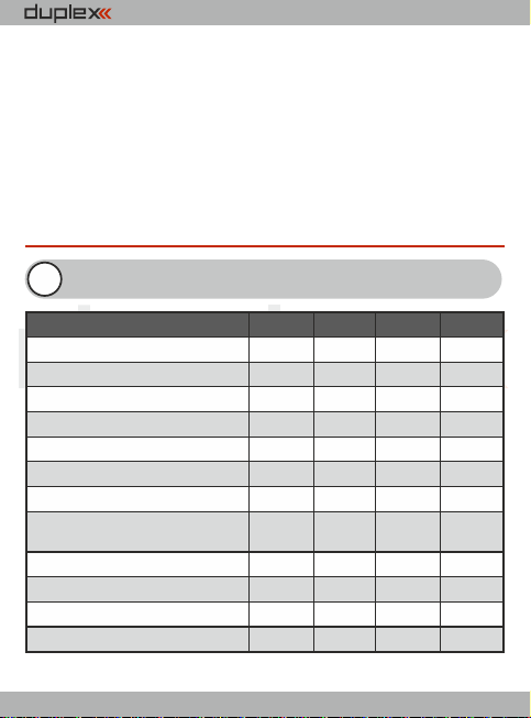
Basic Data
REX6
REX7
REX10
REX12*
Dimensions [mm]
38x25x11
42x28x11
51x28x11
51x28x11
Weight [g]
11
13
16
24
Antenna length [mm]
2x100
2x200
2x200
2x400
# of channel outputs
6710
12
Temperature range [°C]
-10 to +85
-10 to +85
-10 to +85
-10 to +85
Supply voltage [V]
3.5 – 8.4
3.5 – 8.4
3.5 – 8.4
3.5 – 8.4
Average current [mA]
75
757575
Real time transmission
of telemetry data
Yes
Yes
Yes
Yes
Programming
JETIB OX
JETIB OX
JETIB OX
JETIB OX
Support satellite receiver Rsat
Yes
Yes
Yes
Yes
Power output [dBm]
15
151515
Receiver sensitivity [dBm]
-106
-106
-106
-106
EN
earlier Duplex versions. By design, users are not forced to
continually buy new equipment to take advantage of the latest
improvements.
The JETI model company portfolio contains a diverse offering of
electronic modelling equipment like voltage regulators, motor
speed controllers, telemetry data display equipment, telemetry
sensors and, last but not least, DC/DS transmitters. The JETI
model product manfacturing policy is to constantly produce the
highest quality product possible.
2 Technical data
4
* xternal ower onnector E P C
Page 7

computer radio control system
EN
3 Installation
3.1 Voltage supply
When designing the on-board wiring for your project, always pay
attention to the voltage input range of your receivers and servos.
You can con nect supply voltage to the Duplex receivers as
follows:
- directly from the batteries
- via a BEC voltage regulator (either contained in speed
controllers or self contained)
The supply may be connected to the Duplex receivers via:
- the throttle channel (when applying speed controllers with BEC)
- a free receiver output.
- a Y-cable to any arbitrary receiver output
- the MPX connector for receivers with the EPC label which are
equipped with a power supply connector
3.2 Operation
We recommend that you switch on the transmitter first and then
subsequently the receiver. The transmitter confirms the switchingon of the receiver with an acoustic signal. When switching off the
system we recommend that you switch off the receiver first and
then subsequently proceed with switching-off the transmitter.
5
Page 8

computer radio control system
EN
3.3 Binding
When using a new receiver or transmitter it is necessary to carry out
the binding process between them. Transmission between the
receiver and transmitter occurs in fully digital manner, therefore it is
necessary to identify and share the addresses of each device
communicating on the mutual 2.4GHz frequency band.
Procedure:
1. Insert the BIND PLUG (included in the receiver packing) into the
receiver socket labeled Ext.
2. Switch on the receiver – (connect a proper voltage supply to the
receiver). Binding of the receiver may now be performed within 60
seconds. After the 60 seconds elapse the receiver returns to setup
mode and the binding process must be repeated by starting again
from step 1.
3. Switch on the transmitter - the transmitter emits an acoustic
signal announcing the detection of a new receiver.
Binding may be carried out with the aid of the JETIBOX instead of
using the BIND PLUG.
The procedure is as follows:
1. Connect the JETIBOX with the connecting cable to the Ext.
receiver output .
2. Switch on the receiver - (connect a proper voltage supply to the
receiver).
3. The receiver menu appears on the JETIBOX display. Select the
„Pairing“ menu item (push the right arrow button once from the
main receiver display) and then push the upward button. You now
have a period of 60 seconds to bind the receiver. After the 60
6
Page 9

computer radio control system
seconds elapse the receiver returns to setup mode and the binding
process must be repeated by star ting again from step 3.
If the binding process between receiver and transmitter was
unsuccessful, try again.
You may bind an arbitrary number of receivers to one transmitter.
The receiver, however, can only be bound to one transmitter, i. e. the
receiver is only bound to the most recently bound transmitter.
As long as the BIND PLUG is inserted into Ext. input, the receiver is
always in „Normal“ mode, regardless your actual receiver setup.
After BIND PLUG is removed, the receiver returns to your selected
setup mode.
EN
7
Page 10

computer radio control system
EN
4 Real time telemetry
Every receiver is able to transmit the actual voltage supplied to the
on-board system (i. e. receiver voltage) without the need to connect
any additional external sensors. If you want to take advantage of
extended telemetry, connect a telemetry sensor to the Ext. input of
the receiver. If you want to operate several telemetry sensors
simultaneously with one receiver, you must use one or more of the
Expander EX devices, which , when connected to the Ext. receiver
input, gives you multiple inputs for telemetry sensors.
There are two ways to use JETI telemetry. The EX telemetry is
available to owners of the JE TI DC/DS transmitters or the
JETIBOX profi. The 1st Generation Telemetry can be used by
owners of the TU, TG, TF etc. transmitter modules.
4.1 EX Telemetry
This telemetry data is displayed according to user selections in the
DC/DS transmitters and the JETIBOX profi. You will find more
details in actual instruction manuals of the given Duplex EX
equipment.
4.2 - 1st Generation
Connect the JETIBOX to the transmitter module. Switch on the
transmitter and connect the receiver voltage supply (see chapter
„Voltage supply“). The Tx heading appears in the JETIBOX display
and by pressing the push-button R (right button) twice, select the
Mx menu. By pressing the push-button D (down) you will enter the
telemetry sensor or expander menu. You may leave the telemetry
sensor menu by pressing the push-button U(up) slightly longer.
8
Page 11

computer radio control system
EN
5 Receiver setup
5.1 Receiver setup via the JETIBOX
There are two receiver setup modes. The first is receiver setup via
the JETIBOX, JETIBOX profi or JETIBOX emulation in the DC/DS
transmitters, the second one is direct setup of the receiver with a
DC/DS transmitter.
5.1.1 Direct connection between a JETIBOX and the
receiver
Insert one end of the connection cable (included with the JETIBOX)
into the socket labeled Impuls + - (see the right side of the JETIBOX)
and the other end into the receiver socket labelled Ext. Connect a
voltage supply to the receiver (see Voltage supply) or to the supply
socket of the JETIBOX. There is no need to supply voltage when
using the JETIBOX profi.
5.1.2 Wireless connection between a JETIBOX with
transmitter or DC/DS transmitter and the receiver
In this case, connect the JETIBOX with the transmitter (if you are
using a DC/DS transmitter, then select the JETIBOX emulation).
Switch on the transmitter and then connect the receiver voltage
supply. The Tx heading appears on the display along with right and
down arrows. In order to enter the receiver, press the R button
(right), the Rx heading appears on the display and by subsequently
pressing the D button (down) you enter the receiver menu, which
will be displayed just the same as the direct connection mode (see
9
Page 12

computer radio control system
paragraph 5.1.1). Wireless connection is only possible when a
receiver is in“Normal“ mode (MeasureOrSetting->Main Setting -
>Rx mode: Normal).
The JETIBOX can be disconnected only after you disconnect the
receiver voltage supply. You may monitor the on-board state of
your receiver during your model‘s operation. Pay particular
attention, of course, to your setup work. If it is possible, we do not
re co mme nd ch ang in g setu p p aram et ers du ri ng mo del
operation. Set-up work should only be done if there is no danger
of damaging the model or injuring people. For safety reasons
prevent motor activation or remove the propeller!
EN
5.2 Receiver set-up via the DC/DS transmitter
Please see information concerning receiver set-up via transmitters
in the DC/DS transmitter instruction manual. You can find the
DC/DS instructions on the manufacturer‘s website.
10
Page 13

computer radio control system
EN
6 Receiver menu
6.1 Overview of receiver data items
The introductory display shows the receiver type. By pushing the R
key (arrow down) more detailed data of receiver and transmitter
can be displayed.
Pairing - by pushing the U key (arrow up) pairing of the receiver
with the transmitter will be executed. Pairing of the receiver should
only be carried out when JETIBOX is directly connected to the
receiver.
RX/TX- RX item shows the unique production number of the
receiver. The TX item shows the unique production number of the
transmitter, to which the receiver has eventually been paired.
Rx Diag- A1 or A2 item shows which antenna the receiver is using at
present. Kx item informs about the number of transferred channels
(this number depends on the transmitter abilities).
By means of the D key (arrow down) you arrive at the line of basic
mode selections, where you may select read out of measured
values (Measure) or setup of the receiver (Main setting, Out Pin
Set, Auto Set).
6.2 Measure
Measure - enables read out of measured data of the maximum,
minimum, and actual receiver voltage.
Volt Min / Act / Max - the receiver is checking the supply voltage
11
Page 14

computer radio control system
and indicates the limit values and extremes which occurred during
operation; at the same time it also shows the actual receiver
voltage. Without switching on the paired transmitter the values
MAX and MIN will not change, only the value of the actual voltage
ACT will be updated. In order to delete MAX and MIN values, keys L
(arrow left) and R (arrow right) must be pressed simultaneously.
RX Signal Level - strength of radio signal from Tx to Rx.
EN
6.3 Main Setting
Fail Safe - switches the Fail Safe function on and off. If the Fail Safe
function is disabled, there are no signals generated on receiver
outputs in case of signal loss. If the Fail Safe function is activated,
the receiver outputs are generated according to your individual
channel setup selections in case of signal loss („out off“, „hold“,“ fail
safe“).
Signal Fault Delay - the time interval from when the receiver
detects signal loss to when the fail safe control throws are initiated.
After the expiration of this time, the receiver outputs will transfer to
your selected individual channel outputs.
Volt ACT/ALARM - the first item displays the actual receiver supply
voltage, the second value represents the setup threshold level for
alarm purposes. During operation, as soon as the actual voltage
becomes lower than the threshold level, the transmitter emits an
acoustical warning tone.
(This setup is for transmitter modules only. For the DC/DS transmitters,
this alarm is set in the transmitter.)
12
Page 15

computer radio control system
EN
Output Period - output signal period setup (initial setup for the
Autosynchronizing mode with the transmitter). This parameter is
fundamentally influencing servo behaviour. With lower output
period values the reactions (response) of analog servos become
faster, but current consumption increases. With a too low setup
value some servos may even start chattering.
PPM-UDI Mode - data conversion mode can be:
Direct
ź output PPM signal contains data directly from the transmitter,
without conversions and channel mapping
ź conversions and possible channel mapping are applied to
output servo impulses only
ź different channels might be assigned to the PPM signal and
servo output pins
Computed
ź conversions and prospective mappings are applied to output
servo impulses and also to PPM signal
ź servo impulses and PPM signal contain the same information
OutputChannelCnt - setup of generated number of receiver
outputs in PPM. If the receiver receives less channels than selected
in setup, the remaining channels (in Computed mode) will be
replaced by a throw specified by the Fail Safe value for individual
channels. Otherwise, the number of output pulses will be reduced
to the setup number.
13
Page 16

computer radio control system
EN
Rx mode - the working mode of the receiver. Possible choices:
Normal
ź bid irecti ona l co mmu nic ati on be twe en re cei ver and
transmitter
ź select this setup for the model‘s main receiver
ź use the same setup if you use only one receiver in your model
(in case you are using only one Duplex receiver for remote
control)
Clone
ź unidirectional communication
ź if you use several Duplex receivers in the model, for instance in
connection with one transmitter module, then you should
operate one of the receivers in „Normal“ mode and the others
in „clone“ mode
ź the receiver operating in „Normal“ mode is considered to be
the main receiver. One of the transmitter modules is able to
control only one receiver in „Normal“ mode
ź if you want to operate several receivers with only one
transmitter module, you should operate them in „clone“
mode
If you switch the receiver to „clone“ mode, further wireless setup
communication becomes impossible because the receiver is now
communicating only unidirectionally. In order to change the mode
or setup, you have to connect the JETIBOX to the receiver and make
the desired change or switch the receiver back to„Normal“ mode:
1. Insert BIND PLUG into the receiver socket labeled Ext.
2. Switch on receiver
3. Switch on transmitter
4. Execute the desired setup changes, see „Receiver setup“
14
Page 17

computer radio control system
EN
6.4 Out pin set
Setup of the physical receiver outputs.
Set Output pin - selection of output, which goes for the following
setup. The menu item shows, as a decimal number, the throw of the
selected output. Receiver output 1 is labeled as Y1.
Pin Config - receiver pin config can be:
Servo
ź standard impulse output for servos
(-100% = 1ms, 0%= 1,5ms / +100% = 2ms )
Digital
ź the output pin is in a stable LOW condition (log. 0) if the
position of this channel is negative, otherwise this pin is in
HIGH condition (log.1)
ź ensure that pin is used only as logical output, don't draw the
current above 1mA
Input
ź here the pin is configured as an input and its condition
(disconnected/connected to the ground) is sent to the
transmitter as other telemetry data from the sensors
ź it is allowed to keep the pin disconnected or connected to the
common ground of the receiver
ź it is not allowed to connect to a different voltage. The pin
works exclusively in PullUp mode so all you need to test the
function is to connect the signal pin to the ground.
PPM pos.- standard form of PPM signal generation with
positive logic at PPM outputs. The bus idle state is log. 0.
15
Page 18

computer radio control system
PPM neg.- standard form of PPM signal generation with
negative logic at PPM outputs. The bus idle state is log.1.
PPM input - for the given input there a PPM signal is expected
from the connected receiver
JETIBOX EX - telemetry sensor connection or data stream for
JETIBOX
EX Bus/EX Bus H S - digital communication, when transmits
th row and te lem etr y i nfo rma tio n with conf igu rat ion
possibilities of equipment connected to this bus, for instance by
a DC/D S transmitter. This configuration type is used, for
instance, when receivers are connected for example to Central
Box.
Serial UDI12/16 - serial data output suitable for connection of
devices with unidirectional UDI interface (e.g. Vbar).
PPM error code- in case of PPM input mode, an acoustic signal can
be set up to announce that this connected signal is missing. By
loading a character from the Morse alphabet you may set up tones
that will acoustically announce the absence of a PPM signal at the
given receiver output. This acoustical signal is generated by the
transmitter module. In the factory default setup the acoustical
signal is switched off.
SetInChannel - assignment of an actual output (labelled as Yx) or
input channel (labelled as Chx)
16
EN
Page 19

computer radio control system
Output Trim - neutral throw setup for receiver output
Gain A - amplification of the output throw in the negative half-plain
A (from -150 to 0%)
Gain B - amplification of the output throw in the positive half-plain
B (from 0% to 150%)
Signal Fault - setup of the receiver behaviour in case of signal loss,
„hold“- holds the most recent control throw, „out off“ – output
switch-off (no signal generated), „failSafe“ – moves to preset throws
for the individual outputs
FS position - FailSafe output position in case of signal loss
FS speed - sets how quickly the throws move to the FailSafe
positions in case of signal loss
Output Group - setup of given output into a selected group of
output pulses, which will be simultaneously generated by the
receiver.
EN
17
Page 20

computer radio control system
REX 6
REX 7
REX 10
REX 12
Pin1
Y1
Y1
Y1Y1Pin2Y2Y2Y2Y2
Pin3
Y3
Y3
Y3
Y3
Pin4
Y4Y4Y4
Y4
Pin5
Y5/E1
Y5Y5Y5
Pin6
Y6/E2
Y6/E1
Y6Y6Pin7
Ext.
Y7/E2
Y7
Y7
Pin8
Ext.
Y8/E2
Y8/E2
Pin9 Y9 Y9
Pin10
Y10
Y10
Pin11
Bat.
Y11
Pin12
Bat.
Y12
Pin13
E1
E1
Pin14
Ext.
Ext.
Assignment table of receiver outputs:
• - Output types:
Y - servo output, dig. out, dig. input
E1,2 - JETIB OX-EX, PPM out, PPM input, E X-Bus, UDI
Ext. - JETI BOX-EX
6.5 Auto set
Loads a default receiver configuration from preset modes.
Factory default - to reset receiver to the factory settings press and
hold keys L and R simultaneously.
18
Page 21

computer radio control system
EN
7 Receiver update
Duplex REX receivers can be updated via PC with the aid of the JETI
USB adapter. You may find a detailed description of the receiver
update process in the USB adapter instruction manual.
USB adapter
19
Page 22

computer radio control system
FailSafe
SignalFaultDealy
OutputPeriod
Rx mode
Enabled
1.5s
17 ms
Normal
FailSafe
SignalFaultDealy
OutputPeriod
Rx mode
Enabled
1.5s
Auto
Normal
FailSafe
SignalFaultDealy
OutputPeriod
Rx mode
Disabled
1.5s
17 ms (or Auto)
Clone
8 Examples of Rx setup
Classic setup of a single receiver
(for any analogue/digital servos)
- servo impulses are generated on servo outputs
- each output can be assigned to one of the groups from A to H
- servo outputs assigned to one group are generated at the same
time
- between two consecutive servo groups there is a delay of 2.5ms
Classic setup of a single receiver (for digital servos)
The second receiver as a backup (clone mode)
- monitors existing connection between the transmitter and the
receiver in "Normal" mode
- does not suppor t telemetry (or an indication of the signal
strength)
- works in receiving direction only, it never transmits
- any number of receivers in Clone mode can be operated
simultaneously
20
Page 23

computer radio control system
FailSafe
OutputPeriod
E1 or E2
Rx mode
OutputChannelCnt
PPM Mode
Enabled
20 ms
PPM pos.
Normal8Direct
FailSafe
OutputPeriod
E1 or E2
Rx mode
PPM Mode
Disabled
Auto
PPM pos.
Normal
Direct
FailSafe
OutputPeriod
E1 or E2
Rx mode
Enabled
17 ms (or Auto)
EX Bus
Normal
Receiver with the PPM output
- possibility to select PPM pos./neg.
- PPM output can be selected on E1 or E2 output
Receiver with the PPM output in the func tion of
backup receiver
- PPM output can be selected on E1 or E2 output
- no output repetition or fail safe is carried out. Every time the
receiver gets the data packet, output impulses and PPM burst
are generated once maximally
- if the data from the transmitter is not available for the receiver, all
the outputs are in Out-Off mode
Receiver with the EX Bus output
- suitable especially for connection to JETI model devices (such as
Central Box)
- EX Bus can be selected on E1 or E2 output
21
Page 24

computer radio control system
FailSafe
OutputPeriod
E1 or E2
Rx mode
UDI Mode
Enabled
17 ms (or Auto)
UDI12
Normal
Direct
Receiver with the UDI output
- suitable for connection of devices with unidirectional UDI
interface (e.g. VBar)
- UDI output can be selected on E1 or E2 output
- the servo impulses are generated on other servo outputs, it is
possible to connect telemetry sensors to the Ext. connector as
usual
ELECTROSTATIC SENSITIVE DEVICE
OBSERVE HANDLING PRECAUTIONS
For receivers we grant a warranty of 24 months from the day of
purchase under the assumption that they have been operated
in conformi ty with these instructions at recommended
voltages and that they were not damaged mechanically.
Warranty and post warranty service is provided by the
manufacturer.
We wish you sucessful flying with the products of:
JETI model s.r.o. Příbor, www.jetimodel.com
22
Page 25

JETIBOX mini
JETIBOX
Button LEFT
computer radio control system
Button right
Button down
Button up
Button left
Button for switching input Ext./Tx
Button backlight
Button UP U
Button RIGHT R
Button DOWN D
Button LEFT L
Button DOWN
Button UP
EN
Button RIGHT
JETIBOX profi
23
Page 26

computer radio control system
EN
24
Page 27

computer radio control system
THIS DEVICE COMPLIES WITH PART 15 OF THE FCC RULES.
O PE RAT I ON IS SU BJ EC T TO TH E F O LL OW IN G T WO
CONDITIONS(1) THIS DEVICE MAY NOT CAUSE HARMFUL
INTERFERENCE, AND (2) THIS DEVICE MUST ACCEPT ANY
INTERFERENCE RECEIVED, INCLUDING INTERFERENCE THAT
MAY CAUSE UNDESIRED OPERATION.
Warning: Changes or modifications to this device not expressly
Warning: Changes or modifications to this device not expressly approved by Esprit
approved by Esprit Model/JETI USA could void the user’s authority to
Model/JETI USA could void the user’s authority to operate the equipment.
operate the equipment. “This equipment complies with FCC radiation
expos ure limits set for th for an uncontrolled environment. This
NOTE: This equipment has been tested and found to comply with the limits for a Class B digital
equipment is in direct contact with the body of the user under normal
device, pursuant to Part 15 of the FCC Rules. These limits are designed to provide reasonable
operating conditions. This transmitter must not be co-located or
protection against harmful interference in a residential installation. This equipment generates,
uses, and can radiate radio frequency energy and, if not installed and used in accordance with
operating in conjunction with any other antenna or transmitter.”
the instructions, may cause harmful interference to radio communications. However, there is no
guarantee that interference will not occur in a particular installation. If this equipment does cause
Under Industr y Canada regulations, this radio transmitter may only
harmful interference to radio or television reception, which can be determined by turning the
operate using an antenna of a type and maximum (or lesser) gain
equipment off and on, the user is encouraged to try to correct the interference by one or more of
the following measures:
approved for the transmitter by Industry Canada. To reduce potential
radio interference to other users, the antenna type and its gain should
• Reorient or relocate the receiving antenna.
• Increase the separation between the equipment and receiver.
be so chosen that the equivalent isotropically radiated power (e.i.r.p.) is
• Connect the equipment into an outlet on a circuit different from that to which the
not more than that necessary for successful communication.
receiver is connected.
• Consult the dealer or an experienced radio/TV technician for help.
This equipment complies with FCC radiation exposure limits set forth for an uncontrolled
Conformément à la réglementation d'Industrie Canada, le présent
environment. This equipment should be installed and operated with minimum distance 20cm
between the radiator and your body. This transmitter must not be co-located or operating in
émetteur radio peut fonctionner avec une antenne d'un type et d'un
conjunction with any other antenna or transmitter
gain maximal (ou inférieur) approuvé pour l'émetteur par Industrie
Ca na da . D ans le bu t d e rédu ir e l es r isq ue s d e b roui ll ag e
radioélectrique à l'intention des autres utilisateurs, il faut choisir le
type d'antenne et son gain de sorte que la puissance isotrope rayonnée
éq uiva len te ( p.i. r.e. ) ne dép ass e pa s l' inten sité n éce ssair e à
l'ét ablisse ment d' une communication satisfaisant e. This device
complies with the Industry Canada license- exempt RSS standard(s).
Page 28

computer radio control system
Operation is subject to the following two conditions: (1) this device
Under Industry Canada regulations, this radio transmitter may only operate
may not cause interference, and (2) this device must accept any
using an antenna of a type and maximum (or lesser) gain approved for the
interfer ence, includi ng int erference t hat ma y caus e unde sired
transmitter by Industry Canada. To reduce potential radio interference to other
users, the antenna type and its gain should be so chosen that the equivalent
operation of the device. Le présent appareil est conforme aux CNR
isotropically radiated power (e.i.r.p.) is not more than that necessary for successful
d'Ind ustrie Canada applicables aux appareils radio e xempts de
communication.
licence. L'exploitation est autorisée aux deux conditions suivantes : (1)
Conformément à la réglementation d'Industrie Canada, le présent émetteur
l'appareil ne doit pas produire de brouillage, et (2) l'utilisateur de
radio peut fonctionner avec une antenne d'un type et d'un gain maximal (ou
inférieur) approuvé pour l'émetteur par Industrie Canada. Dans le but de réduire
l'appareil doit accepter tout brouillage radioélectrique subi, même si le
les risques de brouillage radioélectrique à l'intention des autres utilisateurs, il
brouillage est susceptible d'en compromettre le fonctionnement.
faut choisir le type d'antenne et son gain de sorte que la puissance isotrope
rayonnée équivalente (p.i.r.e.) ne dépasse pas l'intensité nécessaire à
l'établissement d'une communication satisfaisante. This device complies with
the Industry Canada license-exempt RSS standard(s).
Operation is subject to the following two conditions:
(1) this device may not cause interference, and
(2) this device must accept any interference, including interference that may
cause undesired operation of the device.
Le présent appareil est conforme aux CNR d'Industrie Canada applicables aux
appareils radio exempts de licence. L'exploitation est autorisée aux deux
conditions suivantes :
(1) l'appareil ne doit pas produire de brouillage, et
(2) l'utilisateur de l'appareil doit accepter tout brouillage radioélectrique subi,
même si le brouillage est susceptible d'en compromettre le fonctionnement.
Page 29

computer radio control system
DE
DEUTSCH
1. Einleitung ......................................................................................... 27
2. Technische Daten ............................................................................... 29
3. Übersicht ............................................................................................... 30
3.1 Spannungsversorgung ............................................................ 30
3.2 Betrieb ........................................................................................... 30
3.3 Bindevorgang .............................................................................. 31
4. Echtzeittelemetrie ........................................................................... 32
4.1 EX Telemetrie ............................................................................... 33
4.2 Telemetrie der 1.Generation .................................................... 33
Lomená 1530, 742 58 Příbor
Duplex-System EX:
• Transmitter modules
• Receivers
• Telemetric sensors
• Compatible accessories
• Display units
JETI model s.r.o.
Czech Republic - EU
5. Empfängersetup ................................................................................ 34
5.1 Empfängereinstellungen über die JETIBOX .......................... 34
5.1.1 Direktverbindung zwischen der JETIBOX und dem
Empfänger .......................................................................... 34
www.jetimodel.com
www.jetimodel.de
info@jetimodel.cz
25
 Loading...