

Page 1
400400400
Modellbau Lindinger GmbH
www.lindinger.at
Protected multi-channel servo interface
EN
EN
User Manual
Page 2

400400400
Modellbau Lindinger GmbH
www.lindinger.at
1. Introduction ..................................................................................... 3 EN
1.1 Features ................................................................................... 4 EN
2. Description ........................................................................................ 5 EN
3. Connection ...................................................................................... 7 EN
3.1 Power supply of Central Box 400 ........................................... 7 EN
3.2 A d va n c e d p o w e r s o u r c e s s e t t i n g s o f t h e
Central Box 400 ...................................................................... 10 EN
3.3 Overload protection of servos ............................................ 11 EN
3.4 Connecting Central Box PPM variant ............................ 12 EN
3.5 Connecting Central Box EX Bus variant ........................ 13 EN
3.6 Putting the Central Box 400 into operation ...................... 14 EN
3.7 Alternative functions - logical input .................................. 15 EN
3.8 Alternative functions - logical output ............................... 15 EN
3.9 Installing safety mechanism of connectors ..................... 16 EN
4. Configuration via JETIBOX ....................................................... 17 EN
4.1 Actual values .......................................................................... 18 EN
4.2 Minimum / Maximum values ............................................. 18 EN
4.3 Setting ..................................................................................... 19 EN
4.4 Out Pin Set ............................................................................... 20 EN
4.5 Alter. Function ........................................................................ 21EN
4.6 Alarms ..................................................................................... 22 EN
4.7 Recording ............................................................................. 22 EN
EN
1 EN
Page 3

400400400
Modellbau Lindinger GmbH
www.lindinger.at
4.8 Service information .............................................................. 23 EN
5. Configuration via the DC/DS transmitter ............................. 24 EN
5.1 Settings .................................................................................... 25 EN
5.2 Alternate functions of pins .................................................. 26 EN
5.3 Servo Fail-Safe ....................................................................... 27 EN
5.4 Servo Output Mapping ....................................................... 28 EN
5.5 Telemetry ............................................................................... 28 EN
5.6 Telemetry Min/Max .............................................................. 29 EN
5.7 Recording ................................................................................ 30 EN
6. Data recording ............................................................................... 31 EN
7. Telemetry reading ........................................................................ 31 EN
8. Firmware update ........................................................................... 32 EN
9. Technical specifications of the Central Box ....................... 33 EN
10. Warranty, service and the technical support ....................... 34 EN
EN
2 EN
Page 4
400400400
Modellbau Lindinger GmbH
www.lindinger.at
EN
400400400
1 Introduction
The Central Box 400 is a switchboard designed for the complete
management of servos in large to giant models with an emphasis
on safety. The Central Box 400 has a unique design that provides
overload protection at each servo output. An independent, very
powerful BEC (battery eliminator circuit) for each battery input
makes the Central Box an optimal solution to connect up to 24
servos. The Central Box 400 can manage the batteries and fully
supports the JETI EX telemetry system. Up to two receivers with
serial (PPM, EX Bus, UDI) output can be connected to the Central
Box 400. With a JETI DC/DS transmitter, the full potential of the
Central Box can be used, such as easy configuration of the Central
Box, EX telemetry, and very fast servo response.
3 EN
FW ver. 1.05, ver.1.0 -2015-05
ENGLISH
Page 5

400400400
Modellbau Lindinger GmbH
www.lindinger.at
EN
1.1 Features
Two independent high-powered BEC´s for voltage
stabilization of servos
overload protection on each channel
overload protection on Rx, Ext, and Switch outputs
possibility to connect up to 2 receivers with serial interface
(PPM, EX Bus, UDI)
built-in Expander function with the possibility to connect JETI
EX sensors
input for magnetic switch or RC switch
batteries connected via MPX connector
stabilized voltage output via a pair of MPX connectors
100Hz mode of servo outputs (10ms period)
supports EX telemetry (voltage, current, capacity, and
temperature measurement, overload indication, ...)
internal memory for storage of telemetry data
USB connectivity for connection to PC
easy settings changes via DC/DS transmitter
firmware updatable
suitable for use with high voltage (HV) servos
robust metal construction with mounting holes
LED status indication
each output is individually configurable (channel assignment,
trim, reverse, ATV)
4 EN
Page 6

400400400
Modellbau Lindinger GmbH
www.lindinger.at
EN
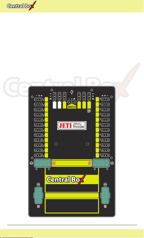
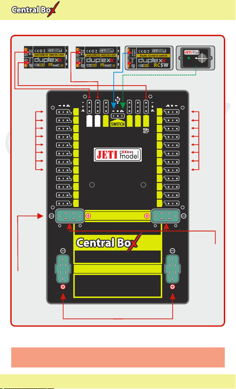
2 Description
Central Box 400 has 24 outputs for servos with individual
overload protection. More over, outputs Y17-Y24 can be
configured as:
servo output
logical input
logical output
Control signals generated by the Central Box to servos are 5V. This
solution ensures reliable servo signal transfer for longer distances.
Ext1 - Ext4 ports can be configured for use as:
inputs for telemetry sensors
EX Bus expanders - used for connecting devices which support the
EX Bus protocol (the Central Box, a sensor,...)
Ext4 - slot is also used as an output to connect a JETIBOX to
configure the Central Box and for the firmware update connection
Rx1 - primary input for connecting receivers with serial output (EX,
PPM, UDI)
Rx2 - secondary (backup) input for connecting receivers with serial
output (EX bus, PPM, UDI)
Switch slot is reserved for connecting magnetic switch or RC Switch
BEC output serves as the output for stabilized voltage to power
supply other Central Boxes that can be power supplied from the
Central Box 400. The voltage at the output has the same level as the
voltage for supplying the ser vos. Voltage for the servo outputs is
adjustable from 5-8V with 0.1V steps.
For more safety, the Central Box 400 contains two BEC regulators
connected in parallel. Information about the correct power supply
and a faultless condition of the individual branches is indicated by
green LED and also by telemetry. It is not recommended to use the
BEC outputs for direct power supply of servos or receivers with
servos. These devices are not individually protected. If one element
of the branch supplied from the BEC output is overloaded, the
5 EN
Page 7
400400400
Modellbau Lindinger GmbH
www.lindinger.at
EN
entire branch is disconnected. The BEC output current limit is 15A.
BATT1 and BATT2 battery inputs
To avoid accidentally disconnecting or pulling the cable with the JR
or MPX connector out, e.g. due to vibrations, it is possible to install
safety mechanism for connectors on the Central Box. Safety
mechanism for connectors fixes not only connectors of servos,
receivers, and sensors, but also BEC outputs (MPX connectors), see
chapter Safety mechanisms of connectors
12
11
10
9
8
7
6
5
4
3
2
1
BATT1 BATT2
24 channel servo interface
Fig. 1: Central Boxu 400 description
Rx 1
Rx 2
Ext1
LED1 LED2
BEC OUT PUT
BATTERY INP UT
6 -17V
6 EN
Ext2
Ext4
Ext3
21
400400400
13
14
15
16
17
18
19
20
21
22
23
24
Page 8

400400400
Modellbau Lindinger GmbH
www.lindinger.at
EN
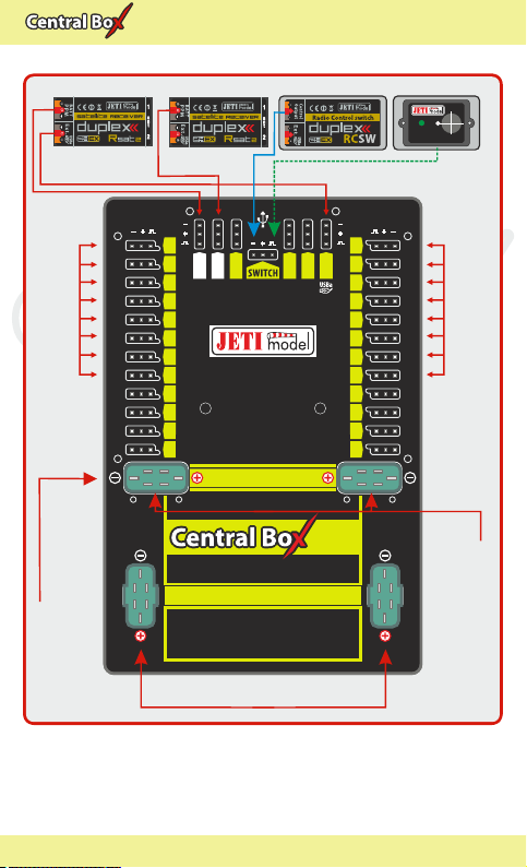
3 Connection
3.1 Power supply of Central Box 400
The Central Box 400 can only be powered from batteries connected
to BATT1 or BATT2. When selecting the power supply it is necessary
to follow the power requirements and the number of the servos you
use. Batteries for power supply must be sufficiently large to prevent
a decrease of the output voltage for servos when loaded (voltage
depression) and to allow the overload protection function properly.
Together, both power supply methods must be able to supply a 20A
continuous and 120A peak current. To take full advantage of
internal BEC we recommend to power the Central Box from three
Lixx cells.
The power batteries are connected to the Central Box using MPX
connectors. The Central Box allows up to two batteries to be
connected. The selection of battery to supply power is based on the
voltage set in individual BEC´s. During use, the power is actually
supplied from the battery whose BEC has higher voltage set. If the
voltage is the same, the power can be used from both batteries at
the same time. This rule applies to the standard power supply. This
means that the power battery voltage should be greater than the
required BEC voltage setting. When the voltage of the batteries is
different, the power is not shared and each pack is isolated from the
other. This allows you to safely use batteries of different capacity,
number of cells, and chemistry type. If the power for the Central Box
is provided only from one battery, it can be connected via either the
BATT1 or BATT2 input.
7 EN
Page 9
400400400
Modellbau Lindinger GmbH
www.lindinger.at
EN
Rsat2 (Rx1)
PPM PPM
Ext.
SERVO standard
Central Box 100
(standard SERVO)
Ext.
12
11
10
9
8
7
6
5
4
3
2
1
Rsat2 (Rx2)
Rx 1
Rx 2
Ext1
LED1 LED2
BEC OUTPUT
RC Switch Magnetic Switch
Ext4
Ext2
Ext3
21
400400400
BATT1 BATT2
BATTERY INPUT
24 channel servo interface
6 -17V
Input Voltage 2-4 LiXX
ON/OFF
ON
13
14
15
16
17
18
19
20
21
22
23
24
SERVO standard
Output Voltage 6V
Fig. 2: Example of the Central Box 400 powered for the use with
standard servos (voltage range up to 6V)
8 EN
Page 10
400400400
Modellbau Lindinger GmbH
www.lindinger.at
EN
Ext.
12
11
10
9
8
7
6
5
4
3
2
1
Rsat2 (Rx2)
Rx 1
Rx 2
Ext1
LED1 LED2
BEC OUTPUT
RC Switch Magnetic Switch
13
14
Ext4
Ext2
Ext3
15
16
17
18
19
20
21
22
23
24
21
Rsat2 (Rx1)
PPM PPM
Ext.
High voltage SERVO
400400400
BATT1 BATT2
Central Box 100
(High voltage servo)
Fig. 3: Example of the Central Box 400 power for use with
HIGH Voltage servos
Caution:
The Central Box can only be power supplied from
BATT1 or BATT2.
BATTERY INPUT
24 channel servo interface
6 -17V
Input Voltage 2-4 LiXX
ON/OFF
ON
High voltage SERVO
Output Voltage 7.4V
9 EN
Page 11
400400400
Modellbau Lindinger GmbH
www.lindinger.at
EN
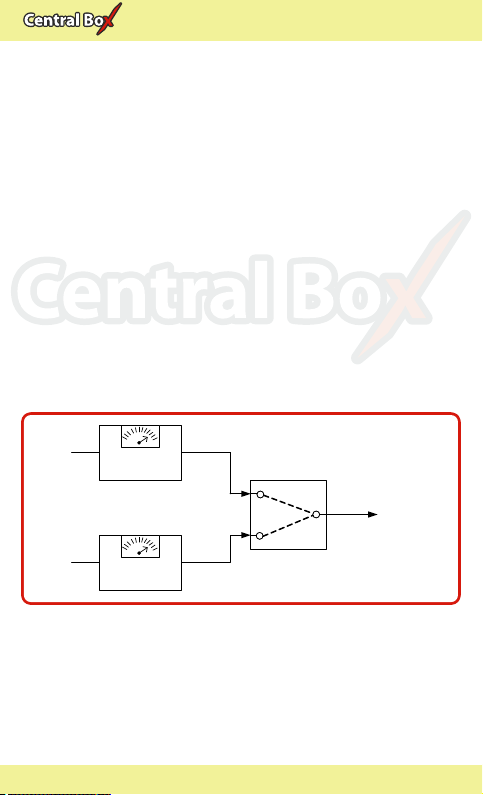
3.2 Advanced power sources settings of the
Central Box 400
In the settings of the Central Box it is possible to adjust the BEC to
the Advanced mode. In this mode you can adjust the voltage of
individual power supplies and thus one source can be used in
preference to the other one. This way you can manage which
battery provides the energy. This can lead e.g. to a situation when
under normal circumstances only one power supply is used. The
other one is intended only as a backup. You achieve this function by
adjusting the supply voltage of BEC1 greater than of the BEC2 or
vice versa. E.g. UBEC1 is 7.4V and UBEC2 is set to the value of 5.5V.
The voltage stabilization of individual power sources can be
deactivated. If the input battery voltage is lower than your settings,
or if there is the same voltage on the BEC and on the input battery,
then the voltage is not stabilized. For example if 6V are used and the
U BEC is set to 8.4V, the voltage of the power supply output is max.
6V, which is not stabilized.
BATT1
BATT2
Fig. 4: The block scheme of power supply.
BEC1
BEC2
UBEC1
UBEC2
10 EN
Mixer
UOUT
BEC OUTPUT
SERVO
Page 12
400400400
Modellbau Lindinger GmbH
www.lindinger.at
EN
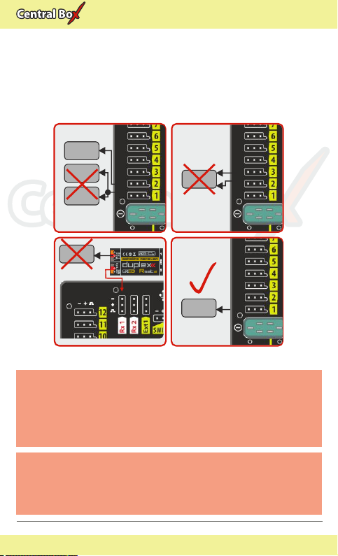
3.3 Overload protection of servos
The Central Box has an overload protection circuit on every servo
output. In case of an overload, the affected servo output is
disconnected from the power supply while the remaining servo
outputs are still powered.
NO
SERVO
SERVO
SERVO
NO
SERVO
Rsat2 (Rx1)
Ext.
Caution:
SERVO
NO
SERVO
Fig. 5: Correct connection of servos to the Central Box
It is prohibited to connect servos directly to any
receiver that is powered from the Central Box 400
(Rx1 or Rx2). In this case the receiver can be fully
disconnected from the power supply, which could
lead to the signal loss.
Caution:
It is not recommended:
- to connect more Central Box outputs to one servo
- to use a Y cable (connecting two servos to one
output)
YES
SERVO
11 EN
Page 13

400400400
Modellbau Lindinger GmbH
www.lindinger.at
EN
3.4 Connecting Central Box PPM variant
If you connect Duplex receivers with a possibility to switch the
output to EX Bus to the Central Box, we recommend the wiring
described in chapter 3.5, EX Bus variant.
The receivers can be connected to the Central Box using the Rx1
and Rx2 inputs.
The Ext4 port is for output of telemetry data from the Central Box in
the form of EX telemetry. To use the Central Box telemetry and other
sensors connected to it, use a Duplex EX receiver. Simply connect
the Central Box output labeled Ext4 with the Duplex EX receiver
input labeled Ext.
Configuring the Central Box is done by using a JETIBOX. You can
either directly connect to the Central Box, or wirelessly connect
using transmitter module, or a JETI transmitter.
Rsat2 (Rx1)
PPM PPM
Ext.
Rsat2 (Rx2)
Sensor
RC Switch Magnetic Switch
Sensor
Sensor
ON/OFF
ON
Fig. 6: Block diagram of Central Box 400 connection - PPM variant
12 EN
Page 14

400400400
Modellbau Lindinger GmbH
www.lindinger.at
EN
3.5 Connecting Central Box EX Bus variant
Receivers can be connected to the Central Box using the Rx1 and
Rx2 inputs.
Ext1-4 are inputs for telemetry sensors. Telemetry is transmitted to
the receivers via EX Bus. Ext1-4 can also be configured as EX Bus
outputs. Configuring the Central Box is, in this case, done directly in
the transmitter via EX Bus.
EX Bus output from the Central Box is an input for devices
supporting this standard, such as Central Boxes and certain sensors.
When operating the Central Box with DC/DS transmitter, it is
recommended to use two receivers communicating with the
transmitter in the wireless mode, Double path".
Ext.
Rsat2 (Rx2)
Sensor
13 EN
RC Switch Magnetic Switch
Sensor
Sensor
Sensor
JETIBOX
Rsat2 (Rx1)
Ext.
Fig. 7: Block diagram of Central Box 400 connection - EX Bus variant
ON/OFF
ON
Page 15

400400400
Modellbau Lindinger GmbH
www.lindinger.at
The Central Box can be configured in two ways:
by connecting a JETIBOX (directly to the Ext4 of the Central Box or
wirelessly via a transmitter/transmitter module)
using DS/DS transmitter or via Device Explorer (EX Bus)
EN
3.6 Putting the Central Box 400 into operation
1. Connect the battery to BATT1 or BATT2 input of the Central Box.
2. Connect the bind plug to the Ext. pin of the auxiliary receiver.
3. Use a three-wire cable to connect PPM output of the receiver
and the Rx1 input of the Central Box.
4. Switch on the DC/DS transmitter. Then the transmitter is paired
with the receiver.
5. Disconnect the bind plug from the receiver. Reconnect the
three-wire cable connecting the receiver with the Central Box.
Disconnect the cable from the PPM output of the receiver and
connect it to the Ext. output of the receiver.
6. In the transmitter me nu Menu ->Advan ce Pr oper ties
->Wireless modules/Trainer switch the mode to Double
path.
7. Connect the bind plug to the Ext. pin of another auxiliary
receiver.
8. Use a three-wire cable to connect PPM output of the receiver
with the Rx2 input of the Central Box.
9. In the transmitter menu M enu->Advanced Proper ties
->Wireless modules/Trainer confirm the item Pair the
secondary TX module.
10. After pairing the transmitter with the other receiver, disconnect
the bind plug from the receiver. Reconnect the three-wire cable
connecting the receiver with the Central Box. Disconnect the
cable from the PPM output of the receiver and connect it to the
Ext. output of the receiver.
11. In the transmitter menu Menu->Model ->Device Explorer
select your auxiliary Rx from the first line and set Serial link to
EX Bus & PPM pos.. Follow the same procedure when setting
the second receiver.
14 EN
Page 16

400400400
Modellbau Lindinger GmbH
www.lindinger.at
EN
3.7 Alternative functions logical input
Using a pin as the input is useful because of simple feedback,
without the use of telemetry sensors.
If you install, for example, limit switches on a retractable
undercarriage, you can have feedback about its condition during
operation. The condition of digital inputs is transmitted via EX
telemetry and sounds or alarms can be assigned to the events.
- This way the pin is configured as the input and its condition
(disconnected, connected to the ground) is transmitted to the
transmitter as other telemetry values from the sensors.
- Only keep the pin disconnected or connected to the common
ground of the Central Box.
- Never connect to a different voltage. The pin works exclusively on
the Pull-Up mode.
Central Box
+
Typ.
Contact, end switch
40k
1
Fig. 8 Example of logical input connection
3.8 Alternative functions logical output
In the digital output mode, only the logical level 1 or 0 is generated
on the port configured this way. The value of this output is
reflecting the assigned output channel and its level. If the servo
position of the specified receiver channel is lower than 0%, (the
decision limit point can be set by the user using the Trigger"
parameter), the output is set to permanent log. 0 (i.e. 0V). If the
servo position is higher than 0%, log. 1 (i.e. 3.3V) will be generated
on the pin. In the digital output mode, no control servo pulses are
generated for that particular pin. With logical outputs, the Central
15 EN
Page 17

400400400
Modellbau Lindinger GmbH
www.lindinger.at
Box is even able to control devices that do not use servo impulse as
their input, e.g. lights, sound generators, etc.
EN
+Vcc
4.7k
Imax=1mA
Central Box
1
Log.0 - 0V
Log.1 – 3.3V
Fig. 9. Example of logical output connection
3.9 Installing safety mechanism of connectors
Vibrations in models powered mainly by gasoline engines can lead
to accidental disconnection of connectors. To prevent this
phenomenon, there is the possibility of installing a safety
mechanism to secure all the connectors. Protective elements 2 and
3 are used to fix the JR connectors. Elements 1 fix MPX connectors.
Screw the distance spacer to the
holes on the front side of the
Ce nt ra l B ox . M ou nt t h e
elements 2 and 3 to the
spacers and tighten them
with M2.5 (torx 8) screws.
Fix the elements 1 with
M2x8 (torx 6) screws.
All the screws are
supplied with the
s a f e t y
mechanism of
connectors.
3
2
1
Fig. 10: Safety mechanism installed on Central Box
16 EN
Page 18

400400400
Modellbau Lindinger GmbH
www.lindinger.at
EN
4 Configuration via JETIBOX
The JETIBOX terminal can be used for parameter setting and
retrieving data. After connecting to the Central Box (output Ext4), a
startup screen appears that contains identification of the device in
the first line of the JETIBOX display. The second line contains the
data showing the consumed capacity of batteries.
By pushing the R button (to the right) on the JETIBOX, you get to the
expander menu.
In the expander menu, the second lines of the sensors menus
connected to inputs Ext1-Ext4 are displayed. Using buttons U and
D (down and up arrows) of the JETIBOX it is possible to browse
through the expander inputs. The selected input is marked with a
curly bracket brace after the input number, e.g. 1}. By pushing the R
button (right arrow) it is possible to enter a selected sensor, where
you can adjust and display its parameters.
Return from the sensor menu:
- by holding the L button (left arrow) for extended time
- by holding the L button (left arrow) for short time, if you
are in the basic menu of the sensor (in the first line there is
identification of the sensor and in the second line there are actual
data, such as MUI 30; 14,2V 7,8A).
The input marked 1}... means that there is no device connected to
this input or the connected device is not compatible, or the input
from the Central Box is not properly configured.
By pushing the D button (down), you get from the initial screen of
the Central Box to its menu.
17 EN
Page 19

400400400
Modellbau Lindinger GmbH
www.lindinger.at
4.1 Actual values
*CENTRAL BOX*:
Actual Value by pushing the D button (down arrow) you select
the display of actual measured values
Accu voltage - shows the actual voltage of both inputs
Accu current - displays the actual current flowing from the
battery to the output
Accu capacity - consumed capacity of each battery
BEC voltage individual voltage of BEC´s
Output voltage Output voltage for servos and MPX output
(merged BEC voltage)
Over-I Monitor - indication of servo output; (-) output is fine (x)
the output is overloaded. Outputs are ordered:
Fig. 11: Description of outputs
Temperature - actual temperature of Central Box
Information on the status of receivers - number of detected
channels and the period of signal
4.2 Minimum / Maximum values
*CENTRAL BOX*: MIN / MAX by pushing the D button (down
arrow) you select a display of extreme records.
Minimal voltage the lowest voltage detected by the Central
Box on the inputs during its operations
Maximal voltage the highest voltage detected by the Central
Box on the inputs during its operation
Maximal current the highest current detected by the Central
Box on the inputs during its operation
Min/Max Temper. - the highest and the lowest temperature of
the Central Box during its operation (since the last manual reset)
18 EN
EN
Page 20

400400400
Modellbau Lindinger GmbH
www.lindinger.at
Statistics of the received signal expressed in time
R1: how long was the signal from the primary receiver available to
the Central Box
R2: how long was the signal from the secondary receiver available
to the Central Box
Statistics of the received signal expressed as a percentage
R1: what percentage of the total operating time was the signal from
the primary receiver available to the Central Box
R2: what percentage of the total operating time was the signal from
the secondary receiver available to the Central Box
Over-I Monitor - indication of servo output during the operating
time of the Central Box; (-) output is fine (x) the output is overloaded
EN
4.3 Setting
*CENTRAL BOX*: SETTING By pushing the D button (down
arrow) you get to the basic setting of the device.
Fail Safe switches on/off of the Fail Safe function. If the Fail Safe
function is deactivated, there is no signal generated in any Central
Box outputs at the signal loss. If you activate the Fail Safe function,
you can also select how the Central Box responds at the signal loss
for each of the individual outputs (OUT off, hold, fail safe).
Signal Fault Delay the length of time from when the Central
Box detects a signal loss to when the programmed Fail Safe output
is performed. During this time the last servo input is held. After the
selected time has elapsed, the Central Box outputs behave
according to setting for each specific output.
Output Period setting for the period of the output signals
(default Auto-synchronous mode with the transmitter). This
parameter significantly affects the behavior of the servos. For
analog servos the reaction (response) accelerates and the power
consumption is higher when the values for the output period are
lower. This can lead to vibration in some servos if the values are set
too low.
19 EN
Page 21

400400400
Modellbau Lindinger GmbH
www.lindinger.at
Erase data by pushing the arrows R and L (right and left)
together, the minimum and maximum are reset, see "Minimum /
Maximum Values".
Output voltage setting the output voltage for servos and MPX
outputs
4.4 Out Pin Set
*CENTRAL BOX*: Out Pin Set pushing the D button (down arrow)
moves you to basic settings of particular outputs of the Central Box.
ChannelOrExt set selecting if the setting is applied to Y1-24
pins (Channel) or Ext.
Setting the channel:
Set Output pin -selection of the output that will be used for the
following settings. In this menu the output deflection of the
selected output is displayed as a percentage. E.g. Y1 is the Central
Box output labeled 1.
SetInChannel assigns the input channel (marked as Chx) to a
specific output (marked as Yx)
Reverse reverses the output direction
Signal Fault - setting behavior of the receiver in case of signal loss
hold - repeats the last valid deflection command before
signal loss
out off does not generate any signal for servo in case of
signal loss
FailSafe transition to preset deflection of individual outputs
FS position setup of the selected output deflection in case of
signal loss
FS speed setup for how quickly the output transitions to its
programmed deflection in case of signal loss
ATV High Limit Yx sets the upper travel (throw) limit of the
output
ATV Low Limit Yx sets the lower travel (throw) limit of the
output
Output Trim setting the neutral deflection of the receiver
output
20 EN
EN
Page 22

400400400
Modellbau Lindinger GmbH
www.lindinger.at
Output Group setting the output to a selected group of output
pulses that will be generated from the receiver at the same time
Ext. setting:
Rx 1-2 a list of signal detection at this input (PPM, EX Bus, L EX
Bus H, UDI, ---)
Ext1-4 setting the Ext functions (Telem. Input, EX Bus, JETIBOX)
EN
4.5 Alter. Function
The Central Box enables using the servo pins also for the purposes
of alternative functions, such as dig. input and output. Switching
from standard servo output to alternative function switches the
whole group of 8 pins to this function
Y1-Y8 Servo output function setting the group of pins 1-8. The
group is either adjusted as the Servo output or Dig. In/output.
Y9-Y16 Servo output function - setting the group of pins 9-16.
The group is either adjusted as the Servo output or Dig. In/output.
Y17-Y24 Servo output function - setting the group of pins 17-24.
The group is either adjusted as the Servo output or Dig. In/output.
Set Output Pin selection of pins that is relevant for following
settings. If you press the arrow down, the function setting (mode)
for the specific pin is depicted.
For the logical output function (dig. output) you can set:
SetInChannel - assigns the input channel (marked as Chx) to a
specific output (marked as Yx)
TriggerLevel - the decision level for logical output. If the servo
position of the specified channel is lower than TriggerLevelY", the
output is set to log. 0. Otherwise the output is set to logical 1.
Reverse - reverses the output direction
Signal Fault - setting behavior of the Central Box in case of signal
loss
hold - repeats the last valid deflection command before signal
loss
log.1 (high) logical 1 is generated on the output.
log.0 (low) - logical 0 is generated on the output.
21 EN
Page 23

400400400
Modellbau Lindinger GmbH
www.lindinger.at
4.6 Alarms
*CENTRAL BOX*: Alarms pushing the D button (down arrow)
moves you to the menu for setting the alarms. If the alarm is set to
OFF, the alarm is deactivated.
Capacity Alarm - level of the capacity taken from the battery at
which the alarm will sound
Current Alarm - level of current drawn from the battery at which
the alarm will sound
Voltage Alarm 1 and 2 if the voltage of batteries drops below
this level, the alarm will sound
Short Circuit Alarm - Activating/deactivating the alarm for when
the outputs are overloaded
Temperature Alarm Activating/deactivating alarms for the
Central Box overheating (if the CB400 temperature is higher than
80°C)
Alarm Rx1 the alarm is generated if the Central Box does not
receive any information about valid servo positions from the Rx1
input for a period longer than 1s
Alarm Rx2 - the alarm is generated if the Central Box does not
receive any information about valid servo positions from the Rx2
input for a period longer than 1s
4.7 Recording
*CENTRAL BOX*: RECORDING pushing the D button (down
arrow) moves you to the menu for data recording.
FileName Size the file name, size and memory usage by the file
into which the data is currently stored.
Total/ Free - summary information about memory usage and the
remaining empty space.
New record setting up a new file
Record CB Telem enables/disables the telemetry of the Central
Box
Record Ext Telem enables/disables saving external telemetry
from the sensors connected to Ext1-4.
Delete memory- complete deletion of the memory
22 EN
EN
Page 24

400400400
Modellbau Lindinger GmbH
www.lindinger.at
EN
4.8 Service information
*CENTRAL BOX*: SERVICE pushing the D button (down arrow)
moves you to the display of the firmware version and the menu for
restoring the default settings of the Central Box.
PresetToSetup pushing arrows R and L (right and left) together
leads to loading the default settings of the Central Box
CBOXxxx v. xx.xx ID xxxxx:xxxxx designation of the product
with the firmware version and the serial number (ID)
23 EN
Page 25

400400400
Modellbau Lindinger GmbH
www.lindinger.at
EN
5 Configuration via the DC/DS transmitter
The Central Box can be configured by a DC/DS transmitter via the
Device Explorer menu. It is necessary to follow these rules for
configuring the Central Box via transmitter:
- Receiver firmware version Duplex 3.12 and newer (with setting
Output mode->EX Bus)
- The receiver must be connected to the Central Box via EX bus
- Transmitter firmware version 2.02 and newer + the device profile
(CBOX400.bin) recorded in the devices directory on the SD card
of the transmitter
When everything is properly connected and configured, the
CBOX400 item appears in the Device Explorer menu. Entering the
item moves you to the configuration menu.
Fig. 12: Device Explorer
24 EN
Page 26

400400400
Modellbau Lindinger GmbH
www.lindinger.at
EN
5.1 Settings
Output Period setting the output signals period (default:
Auto synchronous mode with the transmitter). This parameter
significantly affects the behavior of the servos. For analog servos
the reaction (response) accelerates and the power consumption is
higher when the values for the output period are lower. This can
lead to vibration in some servos if the values are set too low.
Expander Settings setting alternative functions of Ext1-4
pins.
◦ JETIBOX output for connecting JETIBOX, or EX telemetry
◦ Telemetry input input for connecting telemetry sensor
◦ EX Bus - EX Bus output
Voltage Settings setting BEC voltage.
Setting type basic or advanced BEC settings. In the advanced
settings, BEC voltages can be configured individually. By default the
voltage of both BEC´s are the same.
Reset to factory settings - reset to factory setting of the
Central Box
Fig. 13: Device Explorer-General Settings
25 EN
Page 27

400400400
Modellbau Lindinger GmbH
www.lindinger.at
EN
5.2 Alternate functions of pins
Overall setting of alternate functions for individual pins of the
Central Box. Possible settings:
Outpin 17-24 Config.- alternative setting for the group of pins
17-24. The whole group of eight pins is set either as servo output, or
as Digi. input/output.
Digi. output according to the value of assigned channel and
the trigger level, logical 1 or 2 is generated on the output. In case
the value of the assigned channel is lower than Trigger, log. 0 is
generated on the output. Otherwise the output is set to log. 1.
Digi. input the condition of the pin is sent to the transmitter via
EX telemetry.
Fig. 14 Alternative pin configuration
26 EN
Page 28

400400400
Modellbau Lindinger GmbH
www.lindinger.at
EN
5.3 Servo Fail-Safe
Fail Safe switches on/off the Fail-Safe function. If the Fail-Safe
function is deactivated, there is no signal generated in any Central
Box outputs at signal loss. If you activate the Fail-Safe function, the
behavior of the Central Box output corresponds with the setting of
individual outputs (Out off, Hold, Fail-Safe).
Fail-Safe Delay the period of time during which the last valid
servo positions are repeated if the signal loss is detected. After the
selected time has elapsed, the Central Box outputs behave
according to setting for each specific output.
Fail-Safe setup now - sets the current position for the Fail-
Safe value
Mode - Fail-Safe mode for a specific Central Box output
◦ Hold: repeats the last known servo position before the
signal loss
◦ Out OFF: does not generate any signal for servos in case of
the signal loss
◦ Fail-Safe: generates pre-set servo position (value) if signal
loss is detected. Can be programmed with slowdown
(Speed)
The Fail-Safe position can be immediately applied to the Central
Box output if the cursor is on the Value" menu item and you push
the F4 function key. F4 (Apply).
Fig. 15: Device Explorer-Fail Safe
27 EN
Page 29

400400400
Modellbau Lindinger GmbH
www.lindinger.at
EN
5.4 Servo Output Mapping
Servo No. assigning outputs of the transmitter to the Central
Box outputs (Output pin).
Group assigns specific output to the group of output impulses
that will be generated from the receiver in the same time
Fig. 16: Device Explorer-Servo Output Mapping
5.5 Telemetry
Temp. actual temperature of the Central Box
Shorted outputs No. actual number of overloaded outputs
Volta tual voltage of individual outputs of the Central ge In ac
Box
Current actual current drawn from the battery
Capacity capacity taken from the batteries
BEC voltage- BEC output voltage
Output voltage voltage level for servos powering
Fig. 17: Device Explorer-Telemetry
28 EN
Page 30

400400400
Modellbau Lindinger GmbH
www.lindinger.at
EN
5.6 Telemetry Min/Max
Clear Min/Max switch here you can assign a control (switch,
stick or knob) on the DC/DS transmitter which clears the recorded
battery capacity and minimum/maximum values in the Central
Box.
Clear Now allows you to immediately clear the recorded
battery capacity and minimum/maximum values in the Central
Box.
Description of individual items is to be found in the chapter
Minimum/Maximum values.
Fig. 18: Device Explorer-Telemetry Min/Max
29 EN
Page 31

400400400
Modellbau Lindinger GmbH
www.lindinger.at
EN
5.7 Recording
File size the size of the file into which the data is currently
stored.
Free memory - remaining empty space for data storage
Current file current name of the file into which the data is
currently stored.
Start new record - setting up a new file
Record Central Box telemetry - enables/disables recording of
the telemetry
Record Ext. telemetr y - enables/disables saving external
telemetry from the sensors connected to Ext1-4.
Format the internal storage - complete deletion of the memory
Fig. 19: Device Explorer - Recording
30 EN
Page 32

400400400
Modellbau Lindinger GmbH
www.lindinger.at
EN
6 Data recording
Central Box 400 is fitted with internal memory of 8 MB. This memory
is used to store the telemetry from the Central Box and from the
sensors connected to it. The memory has a standard FAT32 file
system. The files containing the telemetry data are located in the
Log. directory. The file name consists of its serial number and a log
file extension, for example. "1.log". When creating a new file, the
number in the file name is increased by 1 compared to the previous
title. The highest number in the file name indicates the most recent
record.
If the memory is full, the oldest file is deleted and the storage
continues. The memory has a capacity of about 1 hour recording at
full capacity, i.e. 4 telemetry sensors connected to the Central Box.
The telemetry recording starts automatically if the Central Box
detects a receiver providing the information on channels on Rx1 or
Rx2 pins. The recording stops automatically when you switch off
the Central Box.
7 Telemetry reading
If you connect the Central Box to the PC using the USB, the Central
Box is detected in the operating system as a mass storage device.
After the Central Box is connected to the PC, it becomes inactive
and can be used only for reading out the data via the PC. If the
Central Box is powered from the batteries, it is necessary to switch it
on and off after it is disconnected from the PC to activate the
memory.
31 EN
Page 33

400400400
Modellbau Lindinger GmbH
www.lindinger.at
EN
8 Firmware update
The Central Box allows firmware update via a PC. The update is
performed using the JETI USBa. The procedure is as shown below:
On t he m an ufa c tu re r / di st ri buto r i nter ne t pa ge s
(www.jetimodel.com), under Downloads, you will find an update
program with the most recent firmware. Download it to your PC.
1. Connect the Central Box output labeled Ext4 with the USB
adapter by means of interconnection cable.
2. Start the firmware update program for the Central Box on your
PC.
3. Switch on the Central Box using the magnetic switch or the RC
switch.
The USB-adapter driver installation instructions can be found in the
USB-adapter instruction booklet
RC Switch Magnetic Switch
ON/OFF
ON
PC
USBa
Power supply
32 EN
USB adapter
Page 34

400400400
Technical specifications of the Central Box 400
Input voltage
6 17 V
Number of connectable accu cells
2-4 LiXX
Continuous current
30A
Output pulse current
230 A
Number of servo outputs
Up to 24
Consumption in the off state with
magnetic switch
60 uA
Consumption in the off state with
RC Switch
140 uA
Operating temperature
- 20°C up to +75°C
Weight
270 g
Dimensions
131x88x19 mm
Modellbau Lindinger GmbH
www.lindinger.at
9 Technical specifications of the Central Box
EN
33 EN
Page 35

400400400
Modellbau Lindinger GmbH
www.lindinger.at
EN
10 Warranty, service and the technical support
Warranty and service
This product is covered by warranty for 24 months after the day of
purchase provided that it has been operated in accordance with
these instructions at the specified voltage and is not mechanically
damaged. When claiming warranty repairs for the product, always
attach a proof of purchase. Warranty and post-warranty service is
provided by your dealer or the manufacturer.
Technical support
In case you are not sure about the setup or some functions of the
product, do not hesitate to contact our technical support. You can
contact either your dealer, or directly the manufacturer
JETI model s.r.o..
For further information see our webpages www.jetimodel.com.
We wish you sucessful flying with the products of:
JETI model s.r.o. Píbor, www.jetimodel.com
34 EN
Page 36

400400400
Modellbau Lindinger GmbH
www.lindinger.at
®
Declaration of Conformity
Issues name & addres:
JETI model s.r.o.
Lomena 1530, 742 58 Pribor
Object of the declaration:
Products: Servo interface
Trade name: Central Box
Model: Central Box 400
Country of origin: Czech republic
The object of declaration described above is in conformity with the
requirements of the folowing EU legislations and harmonized standards:
SN EN 61000-6-1:2007, SN EN 61000-6-3:2007+A1:20011
Electromagnetic compatibility: 6440-454/2008 6440-538/2008
Signed for and on behalf of:
EN
Tomá Klesnil
production Manager
35 EN
Page 37

400400400
Modellbau Lindinger GmbH
www.lindinger.at
EN
36 EN
Page 38

400400400
Modellbau Lindinger GmbH
www.lindinger.at
JETI model s.r.o.
Lomená 1530, 742 58 Píbor
Czech Republic
EN
www.jetimodel.com
www.jetimodel.de
info@jetimodel.cz
 Loading...