

Page 1

IC Radio Standards Specification: RSS-210
Certification Exhibit
FCC ID: ONTJETIDC16US
IC: 10491A-JETIDC16US
FCC Rule Part: 15.247
ACS Project: 12-2095
Manufacturer: Esprit Model
Model: JETIDC16US
User Manual
3998 FAU Blvd. Suite 310 Boca Raton, FL 33431 Tel: 561-961-5585 Fax: 561-961-5587
Page 2
computer radio control system
EN
1 Introduction
The new DC16 transmitter was developed and produced with the
cooperation of professional and world champion pilots. This
transmitter was created with the goals of maximum utility, simple
handling, maximum durability and the ultimate reliability of its
mechanical parts. The metal case, with its chemically resistant
outside surface treatment, provides maximum protection for the
interior components. The straightforward case shape makes
servicing easy. The metal, quad ball bearing equipped, stick gimbals
with their magnetic Hall sensors are another revolutionary design
concept used to make the DC16 one of the world’s most advanced
R/C systems.
Purposefully placed at the top of the transmitter, the 3.8“ backlit, LCD
display with its wide viewing angle offers nearly perfect visibility in
just about any lighting condition. Thanks to its high resolution
display and use of a relatively large number of graphic images it was
possible to create a simple and intuitive setup procedure for
displaying telemetric data.
The DUPLEX EX family of products have been equipped with an
improved telemetric data transfer system which can be viewed on
the LCD transmitter display or saved for later analysis on a PC. The
transmitter allows the setup of audible notifications (optionally
created by the user), which can be related to actual telemetric values
or to sound alarms or signals which have been assigned to
conditions of various control elements.
1.1 Features
Duplex 2,4GHz – the DC-16 transmitter features the Duplex 2.4GHz,
frequency hopping, digital, data stream system originally developed
by Jeti Model in the Czech Republic. This system has been reliably
used for many years.
Built-in Telemetry – from the start, the DC-16 transmitter was
designed and built with many attractive features and includes the
full integration of all Duplex telemetry sensors.
Design of the DC-16 Transmitter – this design emphasizes user
comfort, state-of-the-art appearance, and uses premium quality
materials.
Precise Metal Gimbals – transmitter gimbals equipped with Hall
sensors and ball bearings for precision movement with an almost
unlimited lifespan.
LCD Display – oversized 3.8“ backlit LCD display with 320x240
resolution which is highly visable under any light conditions.
Li-Ion Battery – provides a proven and reliable energy source with a
high capacity (3200mAh) and a long service life.
Easy Charging – simply connect the wall power supply to the
transmitter. The DC-16 may also be charged used through its USB to
PC interface.The charging progress is shown on the DC-16 display.
Integrated Antenna – the antenna covers & tx handle are an integral
part of the transmitter case which protects the RF antennas from
mechanical damage.
1.1.
Page 3
computer radio control system
EN
Large Memory – 4GB memory space for storing models, sounds, and
telemetry data.
USB Connector – convenient connection to your PC. Fast firmware &
sound upgrades, telemetry data downloads.
Fast Navigation – 3D wheel-style interface combined with function
keys allow for speedy navigation within the DC-16 menu.
Digital Trims – fully programmable trims and a revolutionary
automatic trimming function.
Swappable and Assignable Switches – all of the switches on the DC16 transmitter (2- or 3-position) can be easily moved and assigned to
create a custom configuration that works best for your application.
Programming – the logical and intuitive transmitter firmware is
designed to be simple to use. Just follow the step-by-step screens.
The creation of a new model can be accomplished with just a few
easy steps.
Sounds/Alarms – the DC-16 transmitter is equipped with audible
alarms and also allows the use of user-recordable alarms and sounds
to keep you fully informed while also keeping distractions to a
minimum.
1.2 Table of Contents
To make navigation faster, the DC-16 transmitter Instruction Manual
has been divided into 5 basic groups:
1 . Introduction and product support.
2. Basic description and mechanical adjustments.
3. First time switch-on. Basic helicopter and airplane set-up.
4. Advanced programming. Detailed descriptions.
5. PC upgrade/upload, safety information, and special mixes.
Important parts of the instructions are separated from the text and
highlighted according their importance.
Advice Note Warning
Advanced modelers may want to begin with group 3 where you will
get all of the basic information for model set-up. This is the quickest
way to understand the basic ideas of the DC-16 transmitter
programming and with this basic information you can begin to
create your own model. More advanced programming functions are
found in group 4. This is where you can find detailed descriptions of
all of the DC-16 functions. The last section provides detailed
description of firmware upgrades, downloads, and special mixes.
1.1.
Page 4
computer radio control system
EN
1.3 Technical Support
If you feel uncertain about how to set up particular transmitter
functions, do not hesitate to take advantage of our technical
support:
1. Web Site
Either the Jeti Model (manufacturer) or your local distributor’s web
sites offer a wide range of support for the DC-16 transmitter. You will
find advice, tips or frequently asked questions (FAQ) which, in most
cases, contain the answers to your questions.
2. Distributor, Manufacturer
You may also find support at your local hobby shop, distributor, or
directly with the manufacturer Jeti Model s.r.o.
3. Service and Warranty Coverage
Jeti Model CZ exclusively warranties that the products purchased will be
free from defects in materials and workmanship for a period of 24 months
from the date of purchase by the customer. This warranty covers only
those products purchased from an authorized Jeti Model CZ distributor or
dealer. Third party transactions are not covered by this warranty. Proof of
purchase is required for warranty claims. Repair or replacement decisions
are at the sole discretion of Jeti Model CZ or an authorized service
provider. This warranty does not cover cosmetic damage or damage due
to an accident, misuse, abuse, negligence, commercial or research use, or
modification of or to any part of the product. This warranty does not cover
damage due to improper installation, operation, maintenance, or
attempted repair by anyone other than Jeti Model CZ or an authorized
service provider.
Jeti Model CZ reserves the right to change or modify this warranty
without notice and disclaims all other warranties, expressed or implied.
2 Included, Accessories
2.1 Included:
1. 2. 3. Jeti DC-16 Transmitter, Wall Power Supply, Jeti DC-16
Transmitter Aluminum Case, Transmitter Work Pad, Jeti Duplex 4. 5.
R9EX 2.4GHz Receiver + Bind Plug, USB PC Cable, Installation 6. 7.
Hex Key Set (1,5mm; 2mm), Cleaning Pad, Instruction Manuals 8.
3
2
6
5
7
4
1
8
1. 2.
Page 5
computer radio control system
Frequency
2.4GHz
Dimensions
WxLxH (with Antenna)
180x270x40,
(230x270x40)
Weight
1.5Kg
Number of Channels
16
Number of control directions
using all Sticks/Switches/Knobs
Up to20
Resolution
4096 steps
Battery
Li-on 3200mAh 3.6V
Operating Time
Up to 11 hours
Internal Memory
microSD 4GB
Telemetry
Yes
PC Connection
USB mini
Graphic Display
3,8" - 320x240px
Operational Temperature
-10 up 60 °C
EN
2.2. Optional Accessories (Not Included)
• Transmitter Neck Strap Bracket
• Transmitter Tray
• 4-Point Adjustable Harness
• Neck Strap
• Additional switches for DC-16 Transmitter
• Special Switch Removal Wrench
• Tx Sticks with 2- or 3-position Switches/Push Buttons
• Replacement Li-Ion 3200mAh Battery
• Replacement Aluminum Case
• Wireless Trainer Module
• Wide Assortment of 4 to 18-channel Duplex Receivers
• Wide Assortment of Jeti Telemetry Sensors
3 System Specifications
2.2.
Page 6
computer radio control system
EN
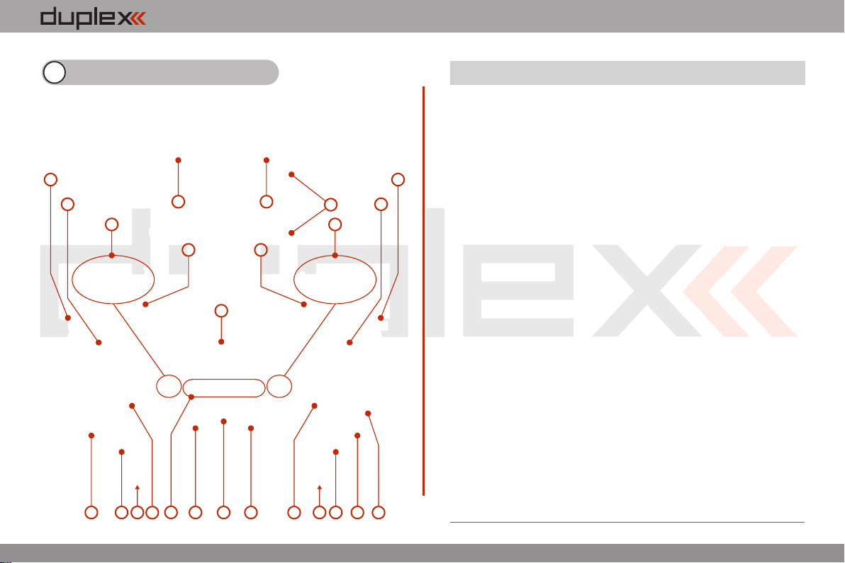
4 Description of Transmitter
2
3
1921
18
10
4
22 22
11
12
2020
4.1. Control Identification
1. Right Stick 1, 2 – the DC-16 Transmitter Supports Modes 1-4, see Control
Sticks -> mode change
2. Left Stick 3, 4 the DC-16 Transmitter Supports Modes 1-4, see Control
Sticks -> mode change
67
17
89
16
3
5
15
1
14
13
3. Swappable and Assignable Switches: Sa, Sb, Sc, Sd, Se, Sf, Sg, Sh, Si, Sj
4. Digital Trims for the Left Stick T3, T4
5. Digital Trims for the Right Stick T1, T2
6. Right Side Control Lever 5
7. Left Side Control Lever 6
8. Rotary Control Knob 7
9. Rotary Control Knob 8
10. LCD Display
11. Function Buttons F1 – F5
12. Transmitter On/Off Power Switch
13. 3D Control Selector
14. Menu Button
15. ESC Button
16. Antenna/ Transmitter Handle
17. Charge Jack
18. USB PC Interface
19. Earphone Jack
20. ON/OFF & Charging LED Indicators
21. Speaker
22. Transmitter Neck Strap Bracket Installation Holes
2.2.
Page 7
computer radio control system
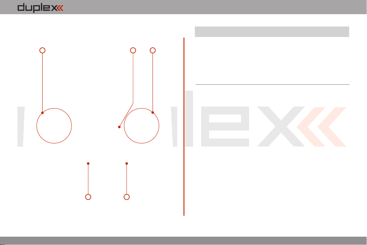
4.2. Assembly Identification
EN
25 2627
24
23
23. Battery Connector
24. Transmitter Battery Pack
25. PPM Output Connector
26. Left Gimbal Assembly
27. Right Gimbal Assembly
2.2.
Page 8
computer radio control system
EN
4.3 Control Stick Assembly
Note:
Warning:
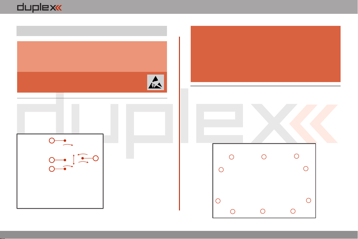
4.3.1. Control Stick Length Adjustment
The stick length is adjustable to suit your flying style. The stick end
separates into two parts.
When handling with back cover removed always
switch-off the transmitter and disconnect the
battery (unplug the connector). Also do not connect
the charging adapter or the USB cable.
Restrict your contact with the printed circuit
boards to a minimum. You can damage your
radio by electrostatic discharge!
1. Hold the top part of the
stick end f irmly and
1
2
3
u n s c r e w ( t u r n i t
anticlockwise).
2. Turn the stick end
clockwise to shorten or
4
c o unter c l ock w i se t o
lengthen the overall stick
length.
3. Adjust the lower part
to support the top part of
the stick end.
4. F in all y s ecur e b y
tightening both parts to
each other.
Warning:
If you have installed optional sticks with switch or
button ends; make sure that while adjusting the
stick length you observe the wires that pass through
the stick shaft and through the gimbal opening in
order to prevent damaging the connecting cables.
The safest method is to de-solder the stick end
switch control wires and remove them from the
gimbal opening during adjustment. (See 4.3.6)
4.3.2. Swivel Control Stick Adjustment
In order to customize the feel of your radio you may adjust the angle
of the stick control assemblies.
1. Switch-off the transmitter and remove the 10 screws that
secure the radio back cover. Next, remove the radio back cover.
Be sure to disconnect the transmitter battery pack connector.
2.2.
Page 9
computer radio control system
EN
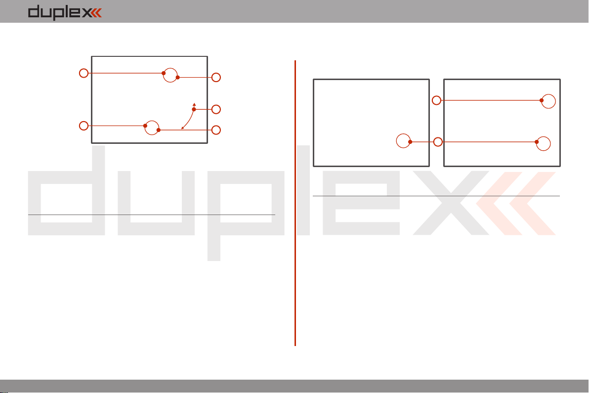
2. Loosen both machine screws securing the control stick
assembly.
2
2
3. Adjust (rotate) to desired position.
4. Securely tighten both machine screws securing the control stick
assembly.
5. Reconnect transmitter battery pack and reinstall radio back
cover and cover screws.
4
3
4
4.3.3. Control Stick Tension Adjustment
The stick gimbal tension is fully adjustable for each axis. This allows
you to fully customize your radio‘s control feel. Simply adjust each
gimbal‘s spring to your desired tension.
1. Switch-off the transmitter and remove the 10 screws that secure
the radio back cover. Next, remove the radio back cover.
Be sure to disconnect the transmitter battery pack
connector.
2. Use indicated machine adjustment screws to change the
desired spring tension.
By turning the screw anticlockwise, you will loosen spring
tension. As a result the moving resistance of the control stick will
decrease. By turning the screw clockwise, you will tighten
spring tension. As a result the moving resistance of the control
stick will increase.
2
2
3. Reconnect transmitter battery pack and reinstall radio back
cover and cover screws.
4.3.4. Ratchet Tension Adjustment
Do you prefer smooth throttle feel or ratchet throttle feel? You can
adjust the DC-16 transmitter either way you like allowing you to fully
customize your radio‘s handling. Each tension is set by a different
machine screw.
1. Switch-off the transmitter and remove the 10 screws that secure
the radio back cover. Next, remove the radio back cover.
Be sure to disconnect the transmitter battery pack
connector.
2. For ratchet tension adjustment use the machine screw “A”.
Turn slowly (anticlockwise) until you achieve the desired
ratchet tension. For smooth tension adjustment, use the
achine screw “B”. Turn slowly (clockwise) until you achieve
2.2.
Page 10
computer radio control system
the desired smooth tension.
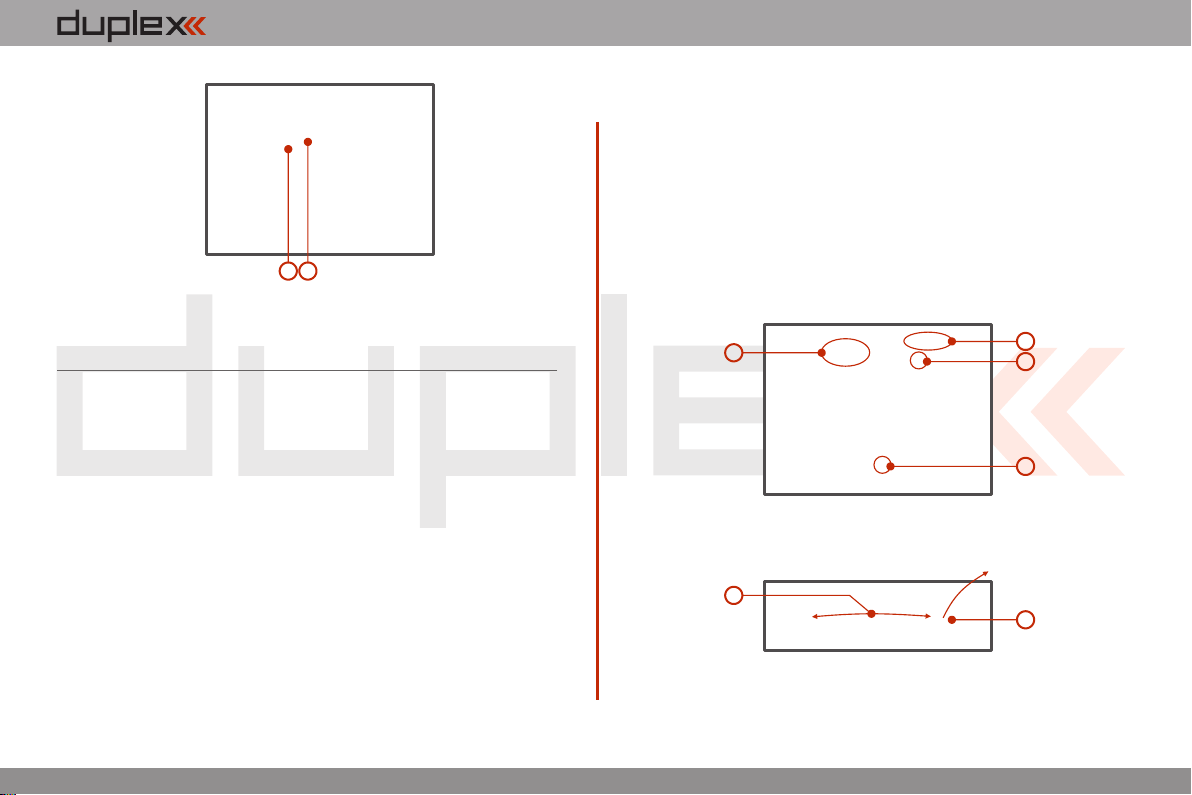
3. Reconnect transmitter battery pack and reinstall radio back
cover and cover screws.
AB
EN
4.3.5. Transmitter Mode Switch
The DC-16 transmitter allows you to switch between Mode 1, 2, 3
and 4 stick configurations with just few simple steps. In order to do
some of these, the stick control assemblies will need to be swapped.
1. Switch-off the transmitter and remove the 10 screws that secure
the radio back cover. Next, remove the radio back cover.
Be sure to disconnect the transmitter battery pack
connector.
2. Disconnect the control stick assembly wires from the Tx board.
(3 wires X, Y, S)
Y
X
3
3. Remove the stick assembly connecting wires from their holders.
It may be necessary to remove the screws securing the RF circuit
board to release the wire group.
6
S
2
4
4
5
4. Remove both machine installation screws for each of the
control stick assemblies.
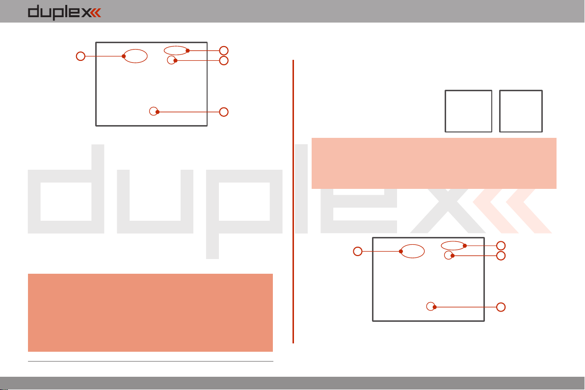
5. Carefully remove both control stick assemblies. Gently pull in
2.2.
Page 11
computer radio control system
EN
Y
X
9
your direction (toward the transmitter back side).
6. Swap both stick unit assemblies and install them back into
correct positions.
7. Reinstall and secure the machine screws for each of the control
stick assemblies.
8. Connect control stick assembly wires to the Tx board connector
(3 wires X, Y, S ). Pay close attention to the wire lengths. Connect
the longest wire as the first one from the outside of the
transmitter (3 connectors X, Y, S).
9. Secure the stick assembly wires into their holders.
10. Reconnect transmitter battery pack and reinstall radio back
cover and cover screws.
Note:
After making a mode switch you must re-calibrate the
transmitter stick assemblies and set-up the correct
mode in the software menu, see section 9.6.1 –
Configuration. The switch between Modes 1 to 3 or
Modes 2 to 4 are done with the software only (NO
manual stick change is necessary).
S
8
7
7
4.3.6. Transmitter Gimbals with Switch or Button
Installation
If you want to operate the DC-16 transmitter using the optional stick
end switch or button functions, you must purchase one or more of
these separately:
• Stick with 2-position switch
• Stick with 3-position switch
• Stick with push-button
Advice:
1. Switch-off the transmitter and remove the 10 screws that secure
the radio back cover. Next, remove the radio back cover.
Be sure to disconnect the transmitter battery pack
connector.
2. Disconnect the control stick assembly wires from the Tx board.
(3 wires X, Y, S)
3. Remove the stick assembly connecting wires from their holders.
For installation of the optional gimbal stick ends with
switches/buttons we recommend that you send your
transmitter to one of the factory authorized service
centers or to your authorized dealer.
Y
X
3
S
2
4
4
2.2.
Page 12
computer radio control system
EN
4. Remove both machine installation screws for each of the
control stick assemblies.
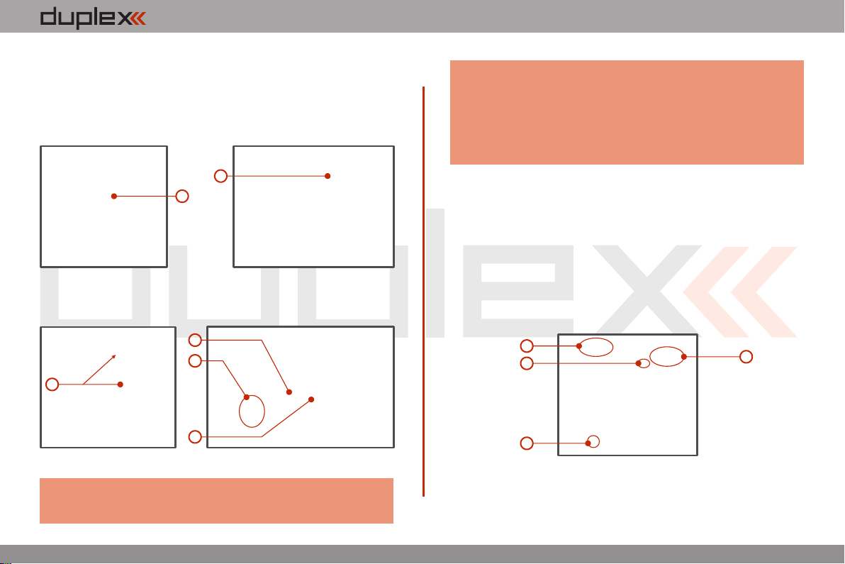
5. Carefully remove both control stick assemblies. Gently pull in
your direction (toward the transmitter back side). This upgrade
will be done outside of the transmitter case.
7
6
6. Unscrew the upper part of the stick assembly (anticlockwise).
7. Insert the connecting wires through the hollow opening of the
transmitter stick.
9
10
8
11
8. Adjust length of the stick to suit your flying style. (See 4.3)
Note:
After installation of the optional stick ends with switch or
button; make sure that while adjusting the stick length
you observe the wires that pass through the stick shaft
and through the gimbal opening in order to prevent
damaging the connecting cables. The safest method is
to de-solder the stick end switch control wires and
remov e them from the gimb al op ening during
adjustment.
9. Pass the switch wires through the same gimbal opening as the
hall sensor cable (through the center of the gimbal assembly).
10. Next insert wire ends through the opening of the printed circuit
board and solder them to the matching soldering points in such
a way that the same color wires lay on the top of each other.
11. Carefully move transmitter sticks to their full outside positions
in order to make sure that you have sufficient wire length and, if
needed, adjust accordingly. The connecting cables for all
moving parts of the unit should have sufficient length in order
not to be exposed to any mechanical damage and any bending
stresses.
12. Install stick unit assembly back to correct position.
13. Install and secure the machine screws for the control stick
assembly.
14
13
13
S
XY
15
2.2.
Page 13

computer radio control system
EN
14. Connect control stick assembly wires to the Tx board connector
(3 wires X, Y, S ). Pay close attention to the wire lengths. Connect
the longest wire as the first one from the outside of the
transmitter (3 connectors X, Y, S).
15. Secure the stick assembly wires into their holders.
16. Reconnect transmitter battery pack and reinstall radio back
cover and cover screws.
Installation and Configuration of Gimbals Switches
After the switch has been installed into the stick assembly you have
to re-configure and enable it in the transmitter software before it will
function properly. This can be done in the transmitter menu „Main
menu->Advanced setup->Sticks/ switches setup“, see section
9.3.2.
4.4 Swappable and Assignable Switches.
One of the most important features of a Jeti transmitter is the switch
function assignment flexibility. The DC-16 transmitter automatically
detects the type of switch and assigns the selected function. The
following switch types are available:
• 2-position short or long switch
• 2-position spring-loaded long switch
• 3-position short or long switch
You may either swap the existing switches around or take advantage
of the optional accessories and create your own custom
configuration.
Factory Switch Configurations for the DC-16 Transmitter
Sa - 2- position spring-loaded long switch
Sb - 3- position short switch
Sc - 2- position short switch
Sd - 2- position long switch
Se - 3- position short switch
Sf - 3- position short switch
Sg - 3- position long switch
Sh - 2- position short switch
Si - 2- position short switch
Sj - 3- position long switch
2.2.
Page 14
computer radio control system
EN
Switch Exchange:
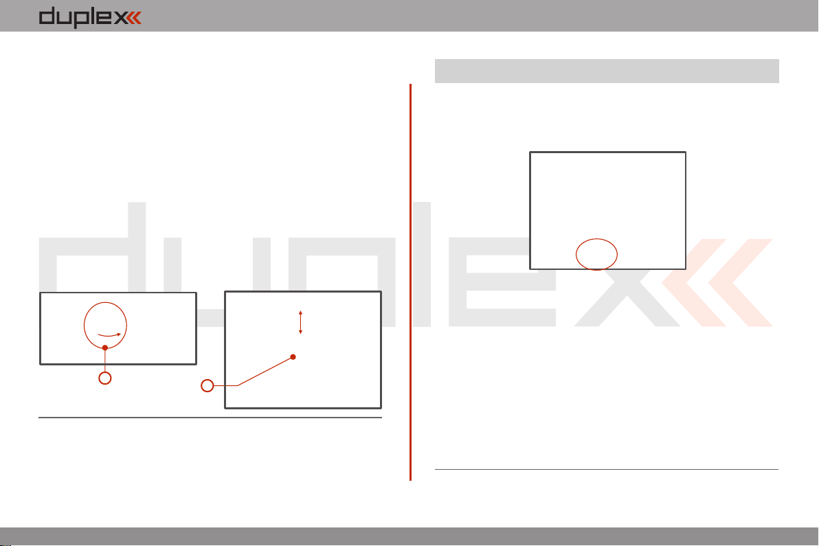
1. Switch-off the transmitter and remove the 10 screws that secure
the radio back cover. Next, remove the radio back cover.
Be sure to disconnect the transmitter battery pack
connector.
2. With the specialized wrench (not included) carefully loosen and
remove the switch installation nut.
3. Carefully hold the switch by its printed circuit board assembly
and slowly pull it out. Use this method to also remove and
exchange all of the other switches. After re-assembling and
turning on your transmitter the software will sound a warning
reminding you that you have executed a change. Always re inspect all assigned functions of the switches before
attempting to fly.
2
3
4.5 Digital Trims.
Transmitter gimbals are used for controlling the basic flight
functions like throttle, roll(aileron), pitch(elevator), and yaw(rudder).
Immediately under the transmitter gimbal sticks you can see four
push-buttons which are the programmable, digital trim buttons.
The digital trims are used for fine trimming of the flying model. When
the transmitter is turned off, the trim values are stored in memory
and are recalled when the system is turned back on.
Every model has its own trim setup. Also all flight modes may be
configured to use different trim configurations. By pressing one of
the buttons, the screen will automatically change to display the
graphic position of that trim. The transmitter trims feature an
acoustic step and centre beep alarm.
In the „Digital trim“ menu it‘s possible to enable a special
function used as automatic trimming. Digital trim steps and trim
range setting is explained in „Main menu->Fine tuning/flight
modes->Digital trim“
2.2.
Page 15
computer radio control system
EN
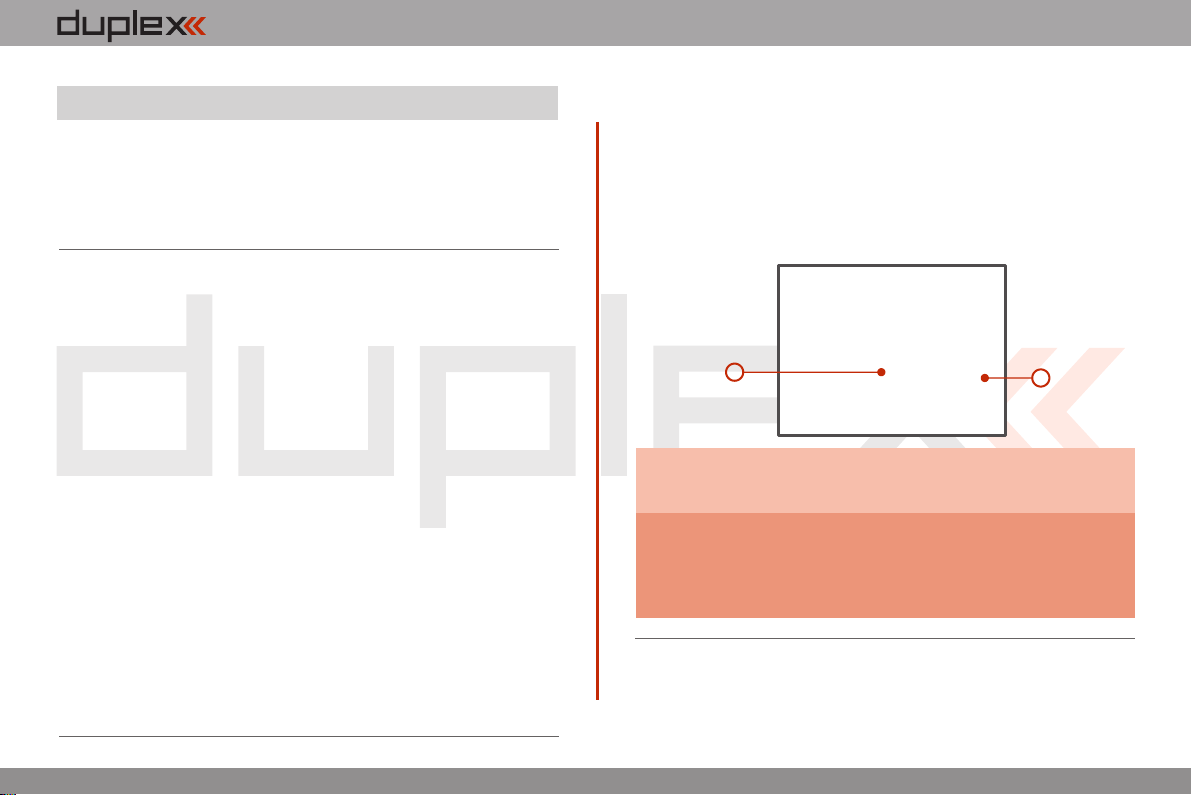
4.6 Transmitter Battery Pack.
The DC-16 transmitter is powered by a Li-Ion type battery pack and
comes equipped with its own built-in advanced battery
management and charging circuit. In switched-on position, the
transmitter LCD display shows the status and condition of the
battery pack. The Li-Ion battery is factory installed.
4.6.1. Charging
The DC-16 transmitter can be charged with the included wall power
supply or through the built-in USB port.
For fast charging use the included wall power supply. Charging time
is around 3 hours. During the charging process the transmitter can
be in switched-on or off position. The charging status is clearly
shown by lit red and green LEDs. If the transmitter is switched on
during the charging process you can see the charging progress
directly on the LCD display.
Transmitter Charging:
1. Plug-in the included power supply to a wall outlet.
2. Plug the main charging connector into the transmitter. If the
green LED goes out, the transmitter is not fully charged. The
red LED indicates the battery charging status.
• Discharged battery – red LED is slow blinking, the green LED
is OFF
Close to full charge – red LED is permanently ON, the green •
LED is OFF
Fully charged battery – the red and green LEDs are ON•
4.6.2. Battery Replacement
Should you decide to replace the transmitter battery, please follow
these steps:
1. Switch-off the transmitter and remove the 10 screws that
secure the radio back cover. Next, remove the radio back cover.
2. Disconnect the transmitter battery connector.
3. Loosen the battery fastening strap and remove the battery.
3
If the transmitter battery has been disconnected for
Note:
longer than 1 minute; the time, and date will be deleted.
Warning:
DC-16 transmitters should only be operated only
with original or manufacturer approved battery
packs. The use of other battery packs will void the
warranty.
2
2.2.
Page 16
computer radio control system
EN
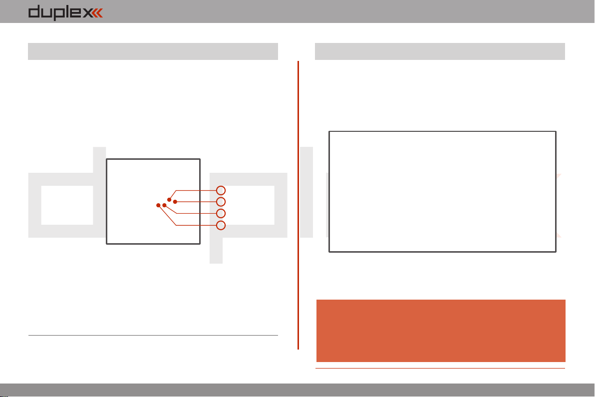
4.7. PPM Output Connector
The PPM output is accessible via connector labeled „B“. This
connector features the non-stabilized battery voltage output in the
range of 3,2V - 4,2V (max. 1A) which can be used as power supply for
the connected HF module as well as for the PPM signal output. The
transmitter output functions are in the form of a standard PPM
signal.
3
4
2
1
1. Reserve pin (do not connect)
2. Positive pin
3. Negative pin
4. PPM signal output (3V logics)
4.8. Handling
The DC-16 transmitter can be comfortably carried by holding it for
the antenna cover/handle as shown on the picture.
Warning:
Before each flying session, and especially with a new
model, it’s important to perform a range check.
If you a re operating a model with a DC-16
transmitter do not shield and avoid contact of the
transmitter antenna with your body.
2.2.
Page 17
computer radio control system
EN
5 RF Transmitter Modules
In order to achieve the highest transmission quality and reliability of
the DC-16 transmitter, we have decided to equip the radio with two
independent DUPLEX 2,4GHz transmitter modules. The transmitter
modules have separate antennas. From the point of transmission
they are fully independent from each other. The RF modules of the
transmitter can operate in following modes:
• „Initial“mode – the primary transmitter RF module is active.
The secondary module can act as redundant unit. If the primary
module does not receive feedback from the receiver, the transmitter
can switch to the secondary transmitter RF module and
communicate with the receiver.
• „Dual“mode – the transmitter RF modules communicate
independently from each other with two different receivers. The
receivers can be interconnected via an intelligent synthesizer, for
instance the JETI Enlink, or the basic control functions can be divided
between two independent receivers. In this mode one part of a
model can be controlled with one receiver using the first transmitter
RF module, the other part of a model with a second receiver and the
second RF module. In an instant you have created a dual, redundant
flying system with two receivers and two RF modules.
• „Trainer“mode – the secondary RF transmitter module is
assigned to communicate with the instructor/student transmitter
only. Communication with the model takes place via instructor’s
transmitter only. If the DC-16 transmitter is in the „Instructor“ mode,
the primary RF module communicates with the model and the
secondary RF module communicates with the student’s transmitter.
In the „Student“ mode the DC-16 transmitter communicates via the
secondary RF module with the instructor’s transmitter. If you operate
two of the DC-16 transmitters; one of them in the „Instructor“ mode
and the other one in the „Student“ mode, the transmitters
communicate between each other via the secondary RF transmitter
module. With this advanced system NO additional equipment is
necessary.
Note:
If you are going to operate the DC-16 transmitter in France, your
transmitter should be setup for French transmitting mode „Main
menu -> System ->Configuration -> French mode -> Yes“
2.2.
Page 18
computer radio control system
EN
6 Transmitter Powering ON/OFF
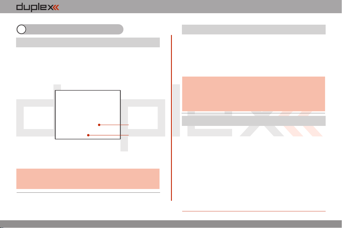
6.1. Transmitter, Powering-ON
Switching-on is achieved by pressing and holding the „Power“
button . The green LED turns ON and the initial screen appears on (1)
the LCD display. At this point transmitter is waiting for final
confirmation – press the F5 (Yes) button . After confirmation, the (2)
main screen is displayed and the transmitter is ready. The power-on
status of the DC-16 transmitter is indicated by the lit green LED.
(2)
(1)
* If you do not confirm powering-on witinin a certain time limit, the
transmitter will turn off automatically. In the DC-16 transmitter setup
you may disable the confirmation by changing in the setup menu
„Main menu->System-> Configuration->Fast switch-on“.
We recommend that you leave the transmitter with the switch-
Advice:
on confirmation enabled, as this function prevents accidental
turning-on and discharging of the transmitter battery.
6.2. Transmitter Turning-OFF
The transmitter is switched-off by pressing the „Power“ main
button. Before complete power-down is achieved you will be asked
for additional confirmation. In case of an emergency, a fast turn-off
can be achieved by simultaneously pressing and holding the
„Power“ and „esc“ buttons. NEVER use this alternative during
normal working conditions.
Advice:
If you want to find out the battery status on a switched-off
transmitter just push the button „Power“ and the initial screen
with the battery status will appear. If you do not confirm
turning-on, the transmitter will shut down automatically.
During the charging process this function is always activated.
6.3. Transmitter Restart
In case of erratic behavior we recommend that you restart the DC-16
to reboot the operation system.
1. Standard switch-OFF and ON with main „Power“ button.
2. If necessary, use the Emergency Switch-OFF by simultaneously
pressing and holding the „Power“ and „esc“ buttons.
3. Disconnect and reconnect the transmitter battery connector.
[ Remove the 10 screws that secure the radio back cover. Next, remove a)
the radio back cover, Disconnect the transmitter battery connector, b)
c) d)Press the „Power“ button to discharge the internal capacitors,
Reconnect the transmitter battery, Reconnect transmitter battery e)
pack and reinstall radio back cover and cover screws, Restart the f)
system. ]
2.2.
Page 19
computer radio control system
EN
7 Initial switching-on
Turn the transmitter on by pressing and holding the „Power“ button
for a couple of seconds and then press the "F5 (Yes)" button to
confirm, see chapter 6.1. The display shows the Main screen and
displays the currently loaded model aircraft.
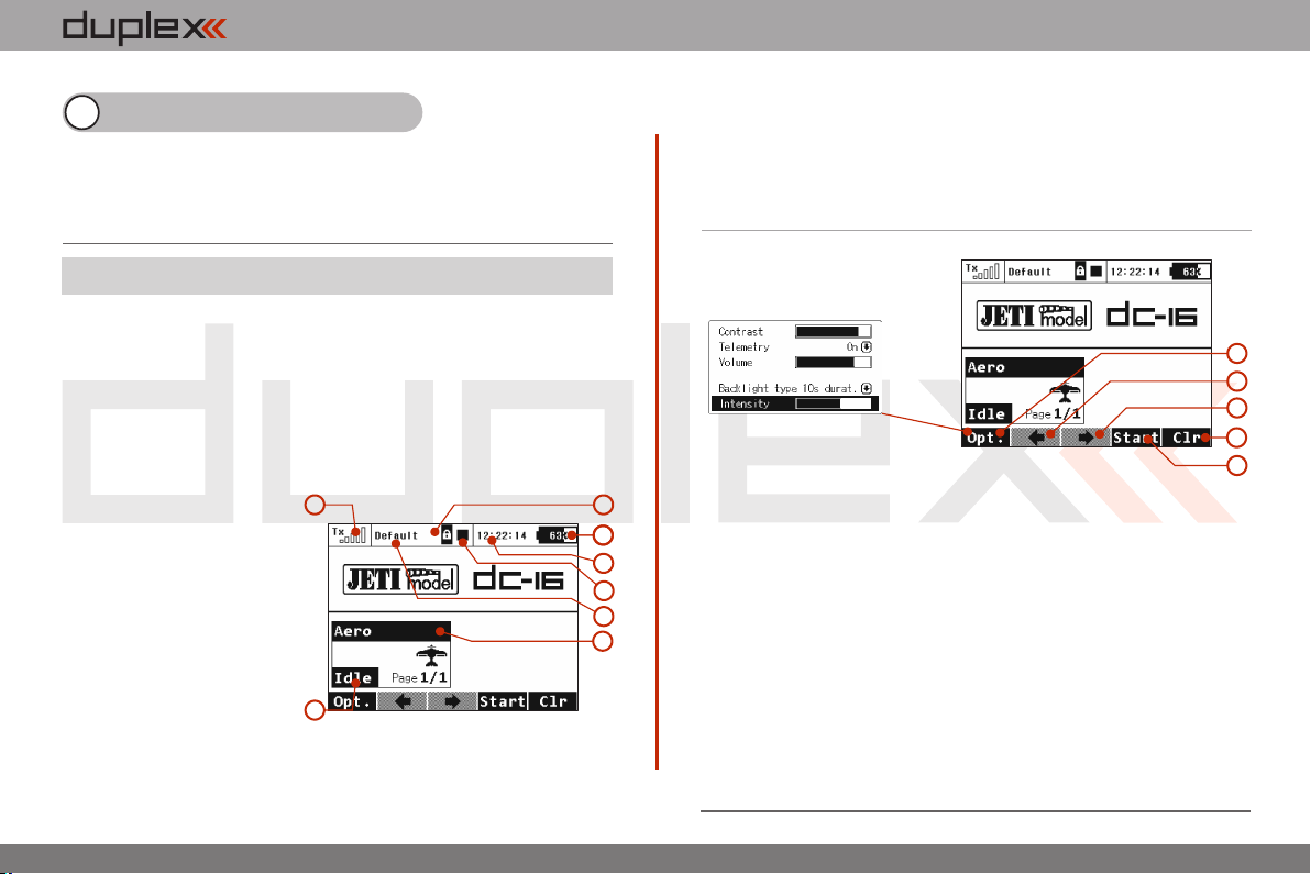
7.1 Main display
The main screen displays basic information about operation of your
transmitter, such as the battery level, time, flight mode, etc. This
screen will also display the user defined information you want to
monitor, for example: stopwatch, telemetry values, etc. The main
screen consists of three main sections: the status bar, the desktop
and the lower bar.
The status bar at the top of the main display displays the following
information:
1. Signal strength
2. Battery status
3. Time
4. Telemetry recording icon
5. Model Name (FIX THE
NUMBER)
6. Name o f ac tu al flig ht
mode
The Desktop is the largest part of the screen. This is where you can
see your telemetry data and where any programmed alarms are
displayed. The Desktop displays your user-defined information
through the use of multiple pages. As you add or remove telemetry
1
8
items or alarms, the number of available pages will automatically
increase or decrease as needed.
In this example, the desktop page displays the following
information:
The lower bar is found at the bottom of the main display.
The lower bar shows:
1. Opt.-fast transmitter set-up: Contrast, Telemetry,
7
2
3
4
6
5
Volume, Duration of Backliting, Backliting Brightness.
2. Left Arrow-move left within the desktop pages.
3. Arrow-move right within the desktop pages.
4. Clr-resets timers
5. Stop/Start-begin and end flight timer, triggering timers or
telemetry recording.
Use the corresponding F1-F5 buttons to select these options
From the main display you may access the main menu by pressing
the „menu“ button. To return from the main menu press either the
„menu“ or „esc“ button.
From the main display, when you push any of the trim buttons or the
3D button the „Trim menu” will be displayed.
7. Throttle Lock (FIX THE NUMBER)
8. Motor cut-off indication, idle
1
2
3
4
5
3.
3.
Page 20
computer radio control system
7.2. Navigation in the Menu
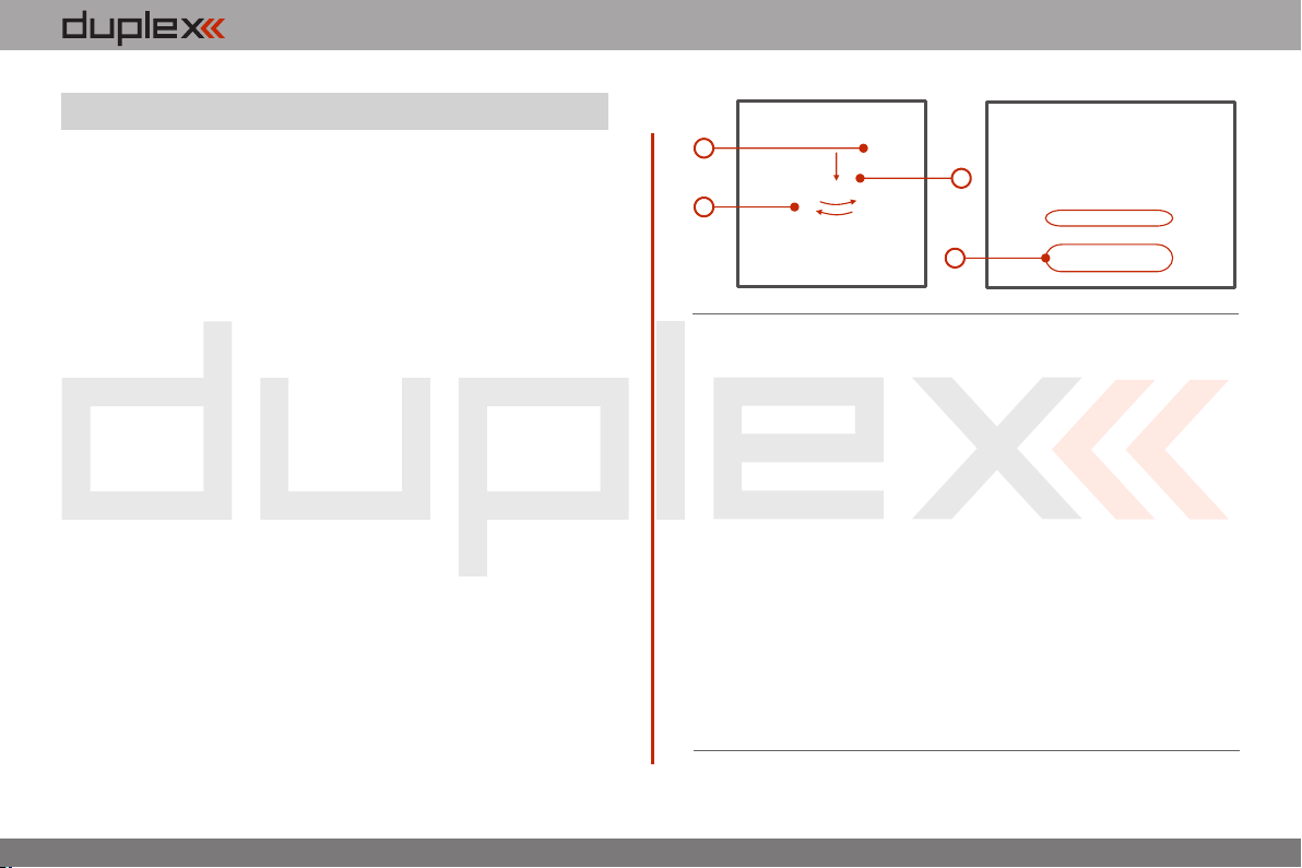
To navigate within the transmitter menus, use the following
buttons:
1. The „menu“ button allows you to switch between the main
display and the transmitter‘s main menu. Also, If you push this
button while turning the 3D Control Selector to edit values, the
values can be changed faster. With the menu button pressed,
10 more values are changed per turn.
2. The „esc“ button allows you to move one level back within the
menu. If you push this button while you are editing a value you
will return one menu level and the edited value will NOT be
stored.
3. 3D Control Selector
3a - by turning the selector anticlockwise you will move up
in the menu. Turning the selector this direction will also
decrease any value you are editing.
- by turning the selector clockwise you will move down in 3b
the menu. Turning the selector this direction will also
increase any value you are editing.
by pressing the selec tor you will confirm your 3c
choice/enter the selected menu.
4. The „F1 - F5“ functions buttons located below the display are
used to select various options based upon the current display.
EN
1
2
7.2.1 Browsing through the Menu
The current selection within the menu (cursor) is designated by
reversed text/shaded graphics. By turning the 3D control selector
left/right you will move through the lines of a menu.
To select an item, first highlight the line and then press the „3D
button“, to select the line. Rotate the the 3D control selector to
highlight your selected item within the line then press the „3D
button“ to select the item. Rotate the 3D control selector either left
or right to change the value of your chosen item. By pressing the
„3D button“ again you will confirm the storage of your selected
value and go back to your previously selected menu item. If you
want to go back to select another line within the previous menu
press the „esc“ button.
Note: For each press of the „esc“ button, you are taken back one
menu level.
3c
3a
3b
3
4
3.3.
Page 21
computer radio control system
EN
7.3 Model Set-up Guide
In this section we will guide you, step by step, through the process of
creating a new model airplane and helicopter. Each step of the guide
will be complete with associated transmitter menu photos. If you
follow the step by step guide you should become familiar with how
to create a model profile. You may even use these concepts and the
„General“ model type to create your own, user-defined model
profile.
7.3.1 Airplane
Let’s create a simple model airplane. Our example will be a motor
glider with ailerons controlled by two servos, an elevator and a
rudder each controlled by one servo.
Servo assignment:
1. Throttle
2. Aileron 1
3. Aileron 2
4. Elevator
5. Rudder
Before you begin creating a model make sure that you have set up
the correct transmitter mode in „Main menu -> System ->
Configuration -> MODE 1-4“. The basic, standardized, assignment of
transmitter inputs to flight controls are based upon this selection.
First it is necessary to first create a model in the transmitter and then
bind the DC-16 transmitter with the receiver which will control the
given model. See chapter 8.4: Receiver->Binding.
Notice:
For safety reasons we recommend first removing the propeller.
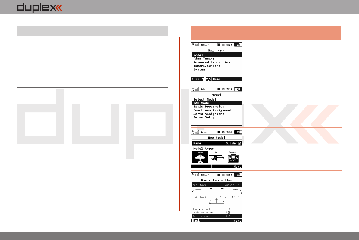
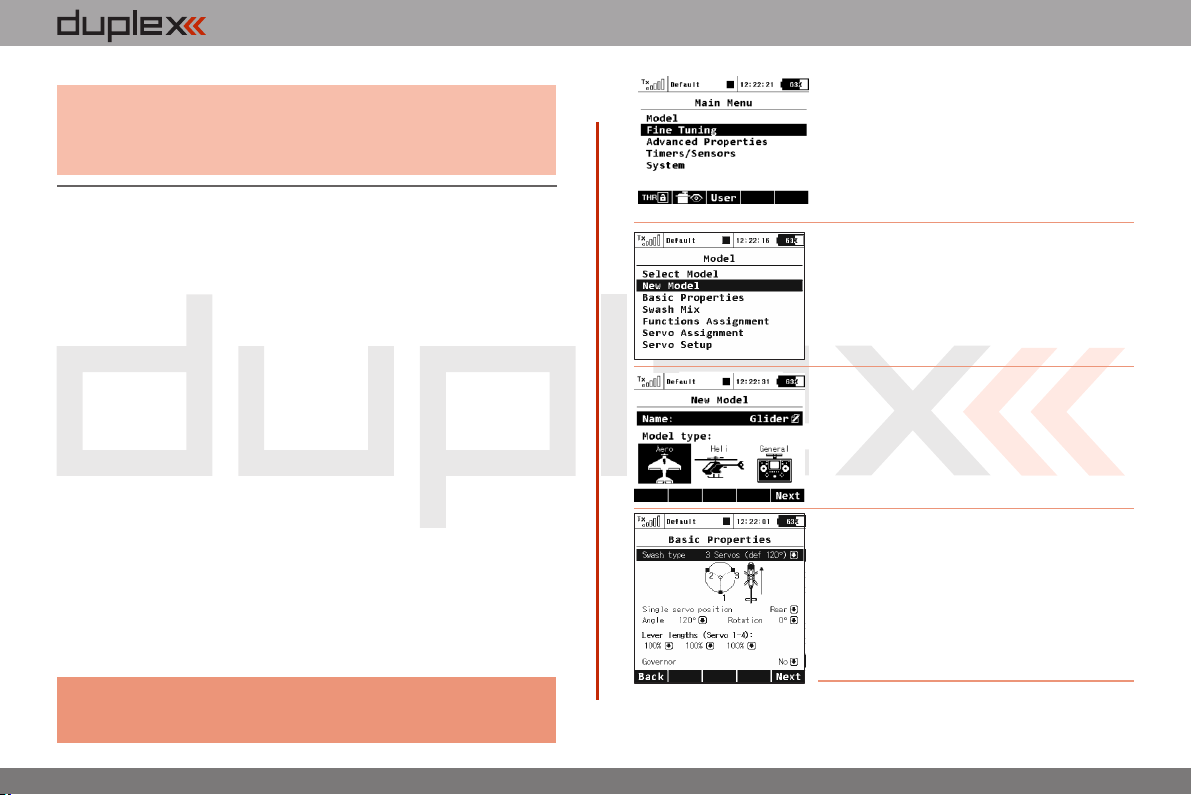
1. Switch-on the transmitter. In the main
display push the key „menu“. Select the
item „Model“ and push the „3D button“.
2. Select the item „New model“ and push
the „3D button“.
3. Enter the name of your model and press
„F5(OK)“ (Note: you must enter a model
name to proceed.) Then select the model
type „AERO“. Confirm by pushing the
„F5(Next)“ button.
4. Select your wing type. Because this
example has 2 aileron servos, select „Wing
type“ 0FLP/2WING. Do not change any
other setup items like tail assembly,
number of motors, number of spoilers or
number of landing gear servos. Continue
by pushing the „F5(Next)“ button.
3.3.
Page 22
computer radio control system
EN
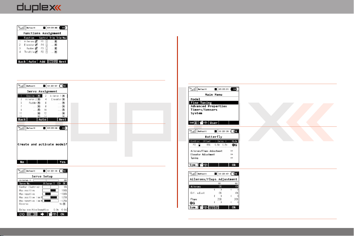
5. This page displays the flight control
functions and their transmitter switch
assignments. Here you can verify that your
flight control functions are correctly assigned
to the transmitter switches/sticks. If they are
not, check and make sure that you have
selected the proper transmitter mode.
Confirm the assignments by pushing the
„F5(Next)“ button.
6. This page displays the assignment of
functions to your receiver outputs (servos).
You may change the assignments by editing
the output assignment for each receiver
channel. Otherways c onfir m with t he
„F5(Next)“ button.
7. The screen will now display a request which
asks if you really want to create and activate
the new model. Confirm with the „F5(Yes)“
button.
8. The Servo Setup menu is where you set the
servo neutral positions, servo output travel
limits, servo reversing, delay etc. You will
come back to this menu after binding the
receiver with your transmitter. Press the
„F5(OK)“ button and you are taken to the main
screen where your new model is displayed in a
desktop page.
Bind transmitter with the receiver, see chapter 8.4 Receiver->Binding.
Once your transmitter has been bound with the receiver and you have
re-applied power to the receiver, the last setup phase is the tuning of
your servo output functions. see chapter 7.3.4 Setup of receiver
outputs.
With this type of wing configuration there is usually a mixer used to also
raise the ailerons as spoilers (spoilerons). Follow the steps below the set
up this mixer. In this example we will use the „right side control
lever(5)“ for the proportional control of the spoilerons.
a). From the main screen, push the „menu“
button. Select „Fine tuning“ and push the
„3D button“.
b). Next, select „Butterfly“ and push the „3D
button”.
c). In the first menu line push the „3D button“
,select „Switch“ and push the „3D button“
again. Next, move the „right side control
lever(5)“. Confirm with the „F5(OK)” button.
The last step in this menu is to set the amount
of travel that your ailerons will move as
spoilerons (or flaperons) and to set any
desired elevator compensation.
3.3.
Page 23
computer radio control system
EN
Note:
When setting up your spoilerons be sure that the ailerons still
have enough travel to control your airplane when the spoilerons
are deployed. In this menu the „(Sym) F1“ button will link or
unlink the spoilerons if you need to set them independantly.
7.3.2 Helicopter
Let’s create a simple model helicopter. In this example, the
helicopter is controlled by a swash plate with three servos at 120°
orientation and the motor has no governor.
Servo assignment for the receiver channels:
1. Throttle
2. Elevator (Swash 1F)
3. Collective (Swash 2L)
4. Aileron (Swash 3R)
5. Rudder (Yaw)
6. Gyro(Gyro sens.)
Before you begin creating a model make sure that you have set-up
the correct transmitter mode in „Main menu -> System ->
Configuration -> MODE 1-4“. The basic, standardized, assignment
of transmitter inputs to flight controls are based upon this selection.
First it is necessary to first create a model in the transmitter and then
bind the DC-16 transmitter with the receiver which will control the
given model. See chapter 8.4: Receiver->Binding.
Notice:
For safety reasons we strongly recommend removing the
main/tail blades or disconnecting the motor when working
with an electric helicopter.
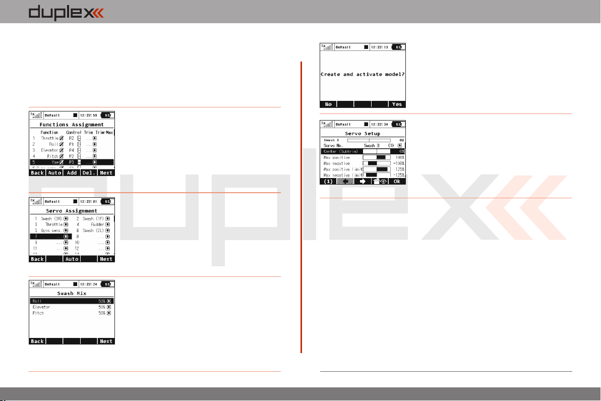
1. Switch-on the transmitter. In the main
display push the key „menu“. Select the
item „Model“ and push the „3D button“.
2. Select the item „New model“ and push
the „3D button“.
3. Enter the name of your model and press
„F5(OK)“ (Note: you must enter a model
name to proceed.) Then select the model
type „Heli“. Confirm by pushing the
„F5(Next)“ button.
4. Select the helicopter swash plate type „3
servos (def 120°)“. Change the second
menu item „Position of front servo“ to
„Rear“ – the swash plate servo orientation
will be turned 180°. Confirm the change by
pressing the „F5(Next)” button.
3.3.
Page 24
computer radio control system
EN
When you create a new helicopter model you are required to define
the swash plate configuration for the model. Please refer to your
helicopter’s instructions and verify that you have the correct swash
plate configuation. If you find that you need to change your swash
plate configuration you can always go to the „Model -> Basic
Properties“ menu to make the change.
5. The„Functions Assignment“ menu lists
the flight functions and their control
switch/stick assignments. If you want to
change any of the switch/stick assignments, select the „Control“ item for your
flight function and then select your desired
switch/stick for that flight function. Press „F5(Next)“ to confirm.
6. The „Servo assignment“ menu displays
the receiver channels and their transmitter
output assignments. If you want to change
any of the output assignments, select the
channel you want to edit and reassign its
output. Otherways press „F5(Next)“ to
confirm.
7. The „Swash Mix“ menu displays the travel
range of each particular helicopter flight
function for the swash plate. The travel
range is displayed as a percentage. You can
use these these travel range adjustments to
prevent linkage binding and to tune the
helicopter to suit your flying style. (Refer to your helicopter’s
instruction manual.) Press the „F5(Next)“ button to confirm.
8. The screen will display a question which
asks if you really want to create and activate
the new model. Press the „F5(Yes)“ button
to confirm.
9. The „Servo Setup“ menu is where you
can set all of your servo neutral positions,
servo output throw limits, servo reversing,
delay etc. You should return to this menu
after you have bound your receiver and
transmitter. See chapter 8.4: Receiver-
>Binding.
10. Once your transmitter has been bound with a receiver and has
been connected to its power supply, the last step consists of tuning
the servo output functions, see chapter 7.3.4: Setup of receiver
outputs.
In the „Fine tuning -> Flight modes“ menu you will setup these
advanced model control functions for your helicopter:
Collective pitch curve, see: Fine tuning -> Flight Modes->Function
Curves
Throttle curve, see: Fine tuning -> Flight Modes->Function Curves
Dual rates, see: Fine tuning -> Flight Modes -> Dual Rate/Expo
Autorotation, see: Fine tuning -> Flight Modes
Gyro/Governor see: Fine tuning -> flight modes -> Gyro/Governor
3.3.
Page 25
computer radio control system
EN
7.3.3 General
The DC-16 transmitter is not only equipped with the assistants for
airplanes or helicopters, but it also has a „General“ assistant which
can be used to create just about any other type of model. If your
model cannot be assigned to the category of an airplane or
helicopter, select the general model. The following setup describes
the creation of a boat model. This process could also be used to
create a profile for any other land/water/air model craft. In this
example, the model is controlled by basic functions like throttle and
rudder as well as by extended functions like a motor sound
generator, lighting system, siren and a smoke generator. The first
three above mentioned functions are controlled proportionally and
the rest are non proportional.
Servo assignment to receiver channels:
1. Motor
2. Rudder
3. Motor Sound Module
4. Lighting System
5. Siren Sound Module
6. Smoke Module
Before creating a model make sure that you have setup the correct
transmitter mode in „Main menu -> System -> Configuration ->
MODE 1-4“. The basic, standardized, assignment of transmitter
inputs to flight controls are based upon this selection.
First it is necessary to first create a model in the transmitter and then
bind the DC-16 transmitter with the receiver which will control the
given model, see chapter 8.4: Receiver->Binding.
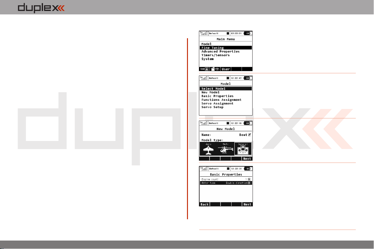
1. Switch-on the transmitter. In the main
display push the key „menu“. Select the
item „Model“ and push the „3D button“.
2. Select the item „New model“ and push
the „3D button“.
3. Enter the name of your model and press
„F5(OK)“ (Note: you must enter a model
name to proceed.) Then select the model
type „General“. Confirm by pushing the
„F5(Next)“ button.
4. The first item in the „Basic Properties“
menu is the number of motors in the
model. In this example, this item will not be
edited and we will proceed to the second
item, which is how the motor needs to be
controlled – i.e. whether the motor turns
only one direction (Single) or both
directions (double). Edit the item „Motor type“ by selecting
„Double direction“. Press the „F5(Next)“ button to confirm.
3.3.
Page 26
computer radio control system
EN
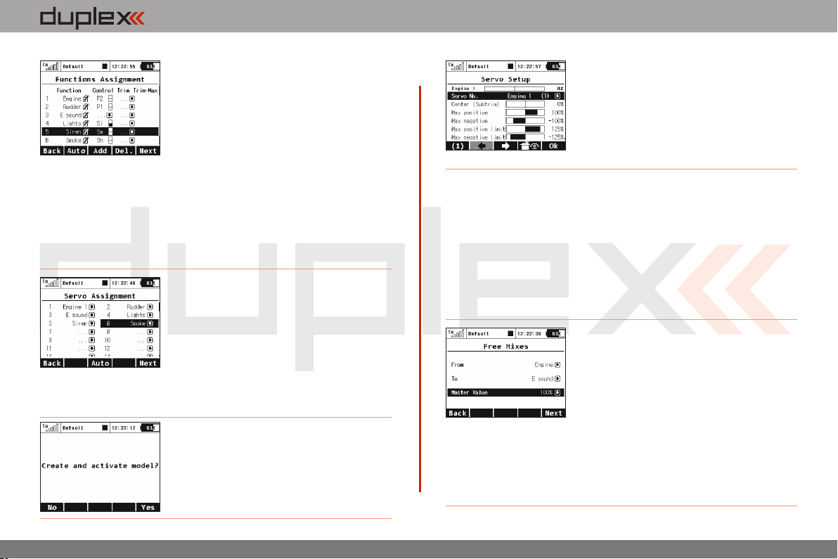
5. In the „Function Assignment“ menu
use the „F3(Add)“ button to create all of
your desired functions. Then you can assign
transmitter control switches/sticks to the
functions by editing each function’s
„Control“ item, see chapter: „S elect
control input“. The only exception is the motor sound module
function, which you cannot simply assign to a control switch/stick,
because it wil be controlled by a mixer. The mixer will allow the
motor sound will be played proportionally to the motor speed. For
the siren function you may take advantage of the switch „Sa“
(spring-loaded switch). After you create of all of your desired
functions press the „F5(Next)“ button to confirm.
6. The „Servo assignment“ menu displays
the receiver channels and their transmitter
output assignments. The channels are
assigned in the order that you created the
functions in the previous menu. If you want
to change any of the output assignments,
select the channel you want to edit and
reassign its output. Otherways press
„F5(Next)“ to confirm
7. The screen will display a question which
asks if you really want to create and activate
the new model. Press the „F5(Yes)“ button
to confirm.
8. The „Servo Setup“ menu is where you
can set all of your servo neutral positions,
servo output throw limits, servo reversing,
delay etc. You should return to this menu
after you have bound your receiver and
transmitter. See the chapter 8.4: Receiver-
>Binding.
Once your transmitter has been bound with a receiver and has been
connected to its power supply, the last step consists of tuning the
servo output functions, see chapter 7.3.4: Setup of receiver
outputs.
To complete this model we just need to configure a free mixer from
the throttle function to the motor sound module. In this example we
will set a switch to enable/disable the mixer so that when the switch
is „on“ the motor sound module is controlled with the throttle
(motor speed). Go to the „Fine tuning -> Free mixers“ menu.
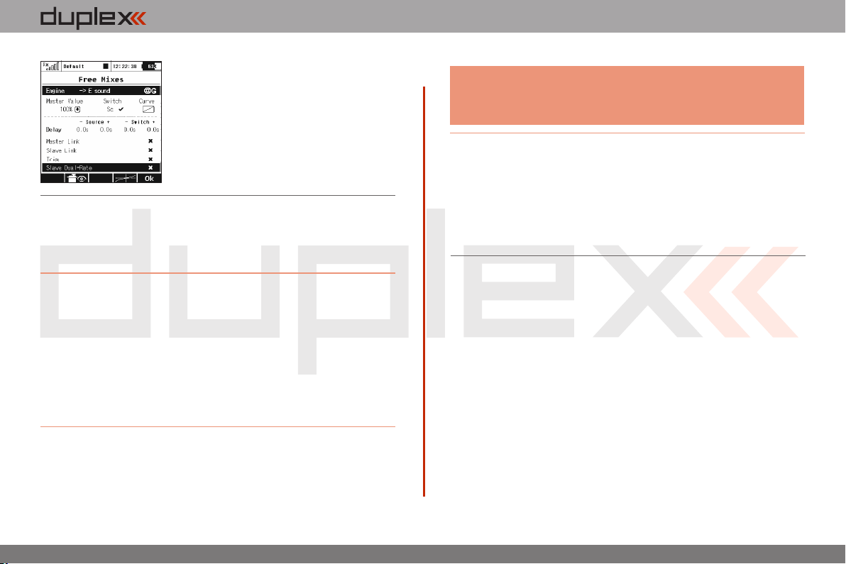
a). Use the „F2(Add)“ button to create a
new mixer. Select „Engine“ in the „From“
item. Then select „Sound M“ (the name of
the sound function) in the „To“ item. The
item „Master Value“ represents the
amount of mixing from the input function
to the output function for this mixer. With
the „F5(Next)“ button you will create the
mixer and the display will change to show
the overview of your programmed free
mixers.
3.3.
Page 27
computer radio control system
EN
b). To assign a switch for the activation and
deactivation of the free mixer press the
„F4(Edit)“ button. Select and edit the
„Switch“ item to assign a switch/stick to
enable/disable the mixer.
7.3.4 Set-up of Receiver Outputs
Go to the „Model->Servo Setup“ menu. Use the „F2“ and „F3“
buttons to brows through the receiver outputs (channels).
You can scrol through the following servo adustment items for each
channel:
„Servo reversing“ – reverses the servo throw direction.
Move the stick for your selected channel and observe the direction
of the servo movement. If the servo moves in the opposite of your
desired direction, change the direction by editing the „Reverse“ item
for that particular servo. Continue with each channel until all of the
servos travel in the required directions.
„Center (Subtrim)“- adjusts the center position of each servo’s
output.
Note:
You should Mechanically adjust all of your servo arms and servo
linkages to be as close to neutral or center as as possible so that
you will need as little subtrim as possible. Using large amounts of
subtrim can limit the overall throw of your servo.
„Max/Min. limit“ – sets the absolute maximum servo output throw
Use these to limit the maximum range of servo throw in order to
keep your servos from exceeding their mechanical limits or to keep
your servos from binding when moving their arms or linkages to
their full travel. You should use the dual rate function to set your
model’s useable control throws.
With your sticks in their neutral positions, scroll through each servo’s
page and use the „Center (Subtrim)“ item to correctly set all of your
servo‘s center or neutral positions.
3.3.
Page 28
computer radio control system
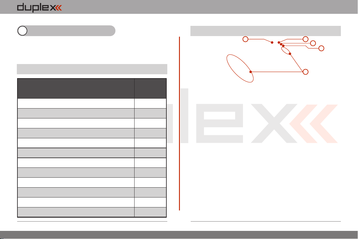
Basic parameter
R9
Dimensions [mm]
51x24x11
Weight [g]
13
Antenna length [mm]
2x200
Numberof output channels
9
Operation temperature [°C]
-10 až +85
Supply voltage [V]
3.2 – 8.4
Average current [mA]
30
Telemetric data transfer in real time
ANO
Programming
JETIBOX
Support of satellite receivers Rsat
ANO
Maximum output power [dBm]
20
Receiver sensitivity [dBm]
-106
EN
8 Receiver
A part and parcel of the DC-16 transmitter is the receiver DUPLEX R9
EX, a nine channel full range receiver with telemetric data transfer.
8.1. Technical Data
8.2. Description
5 4
1. The R9 receiver has 9 channels (numbered 1-9). This receiver
uses the universal or „JR Type“ servo connectors.
2. Bat - receiver and servo power supply input. Whenever
possible, always supply power to your receiver using more than one
of these inputs. You can either supply power through the use of a Ycable or through any unused receiver channel connection. To power
the receiver you may use NiCd packs, the BEC from your ESC or Li-xx
cells used with a voltage regulator, such as the JETIMAX BEC or
similar.
3. SAT - auxillary input/output for PPM signals. This input allows
you to connect an additional JETI DUPLEX Rsat2 satellite receiver.
This allows you to increase the number of receiver antennas in your
system for increased reliabilty in installations with shielded or badly
oriented antennas.
4. EXT - input for telemetry sensors. If you want to connect more
than one telemetry sensor then use the JETI EXPANDER E4. You can
„daisy-chain“ several of the E4 Expanders to support many, many
sensors.
5. A1/A2 - receiver antennas. The antennas should be installed
so that the wires form a 90° angle relative to each other.
3
2
1
3.3.
Page 29
computer radio control system
EN
8.3. Installation
Whenever possible, you should wrap the receiver in foam and place
it as far as possible from sources of interference (servos, electric
motors). Arrange the receiver antennas so that their active ends form
a 90° angle and try to put them as far as possible away from each
other. Take care not to bend them with a radius smaller than 1 cm.
The active part of the antenna should not be placed close to metal
parts. If your model has a carbon fuselage it is very important to
place the active antenna ends outside the fuselage.
8.4. Binding
In order to achieve communication between transmitter and
receiver you must bind them. During this process the transmitter
learns the receiver address and will automatically find it again when
switched back on. Communication begins with this receiver
automatically if the transmitter is not already communicating with
another receiver. The binding process needs only to be done once
for each receiver.
Procedure:
1. Switch off the transmitter and receiver.
2. Plug the „BIND PLUG“ into the EXT receiver input.
3. Connect receiver power supply.
4. Switch on the transmitter. The receiver will bind with the
primary transmitter module.
8.5. Range Test
The range test will verify that the transmitter and receiver are
functioning properly.
Before the first flight of each flying session or if have any doubts
about the transmitter or receiver function you should always check
the range. During the range test the transmitter’s output power is
decreased to 10%.
When performing a range test, both the model and the transmitter
should be at a minimum height of 80 cm (31.5“) above the ground. A
correctly functioning transmitter and receiver in range test mode
should safely control a model to a minimum distance of 50m (164‘).
If not, check your model’s antenna installation first. If the test is still
not successful don´t fly the equipment and contact your retail shop
or one of the Jeti authorized service centers.
8.6. Fail safe
All Duplex 2,4GHz system receivers are equipped with „fail safe“, a
function which reacts to control signal transmission interruptions.
When your receiver for any reason does not receive transmitter
information it changes, after a pre-set time period, to one of the
following modes.
„Repeat“ – This mode holds the last valid control throw signal ( this is
the default mode for all receivers)
„Out off“ – There is no output signal provided by the receiver, i. e.
servos do not keep their positions
„Failsafe“ – receiver outputs change to preset positions
3.3.
Page 30
computer radio control system
Each receiver channel can be configured to one of the modes
described above. We recommend that you setup „fail safe“ positions
for every output which enables your model to stay in a stable
condition. For instance, the elevator and rudder in neutral positions,
electric motor switched-off, gas engine idling, spoilers extended.
Configuration Method of the receiver failsafe function.
1. Bind receiver with transmitter. See chapter: 8.4 Binding. Leave
receiver and transmitter in switched-on condition.
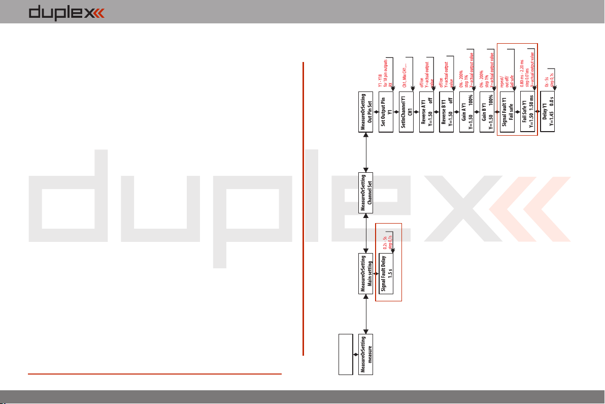
2. In the transmitter, go to the menu „System->Jetibox“ and
proceed according to picture. Use the F1-F4 function buttons to
move within the menu.
3. In the „Set Output Pin“ menu select the receiver output which
you want to configure (use the left/right buttons) and proceed (by
using the down-button).
4. In the „Signak Fault Yn“ menu where n denotes the channel
number which has to be configured, use the right-button to edit the
output function showing a signal failure (set-up „fail safe“). You have
now activated the „fail safe“ function on receiver channel output n.
5. The „fail safe“ is adjusted by pressing the down-button and
changing to the „fail safe“ menu. With the left/right buttons edit the
„fail safe“ value in a range of 0,8ms to 2,2 ms. Adjust all of the
connected receiver outputs by repeating steps 3-5.
The last parameter to be set up is the elapsed time after signal failure
when the „fail safe“ or other actions after signal failure will be
initiated. In the „SignalFault Delay“ menu you can define the length
of time after a signal fault occurrs in which the preset throws are
applied. The values in this menu are changed by pressing the
left/right.buttons.
EN
Receiver Type
Duplex R9 EX
3.3.
Page 31
computer radio control system
EN
9 Main menu
You reach the basic menu from the main display by pressing the
„menu“ key.
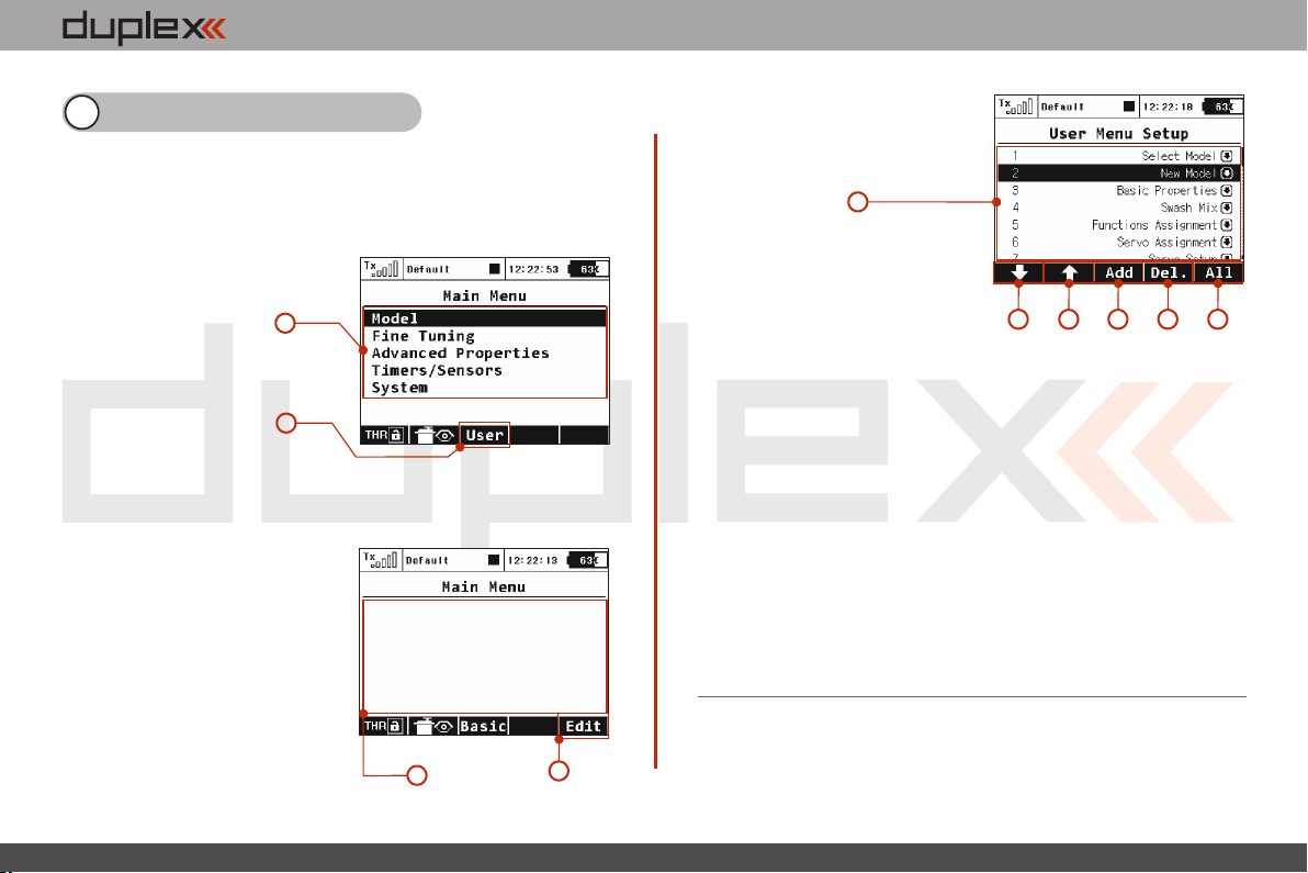
1. The main menu is divided into a basic and a user section. In
the basic menu, the menu items are divided into sub-menus.
• Model
• Fine Tuning
• Advanced Properties
• Timers/sensors
• System
2. You enter into the user sectionof the main menu by pressing
the F3(User) button. In this section you may create a custom, user
defined menu according to your needs.
3. In the ba sic s etu p the
menu contains no items.
4. By pressing the „F5(Edit)“
button you will enter into the User
Menu Setup section.
1
2
5. The numbers on the left side
of the display shows the sequence
of the menu items.
5
7
66
6. With the „F1“ and „F2“ buttons you may change the sequence
of the selected menu items.
7. With the „F3(Add)“ you will create a new item in the user
section of the main menu. By pressing the „3D button“ when the
menu item is selected, you will change to the selection menu of that
item.
8. With the „F4(Delete)“ button you will delete the selected
menu item.
9. With the „F5(All)“ button you will insert all of the possible sub-
menu items into the user menu.
In both sections there are functions like throttle lock and servo
monitor which are accessible by using the „F1(THR)“ and
„F2(Receiver output)“ buttons.
98
3
4
4. 4.
Page 32
computer radio control system
EN
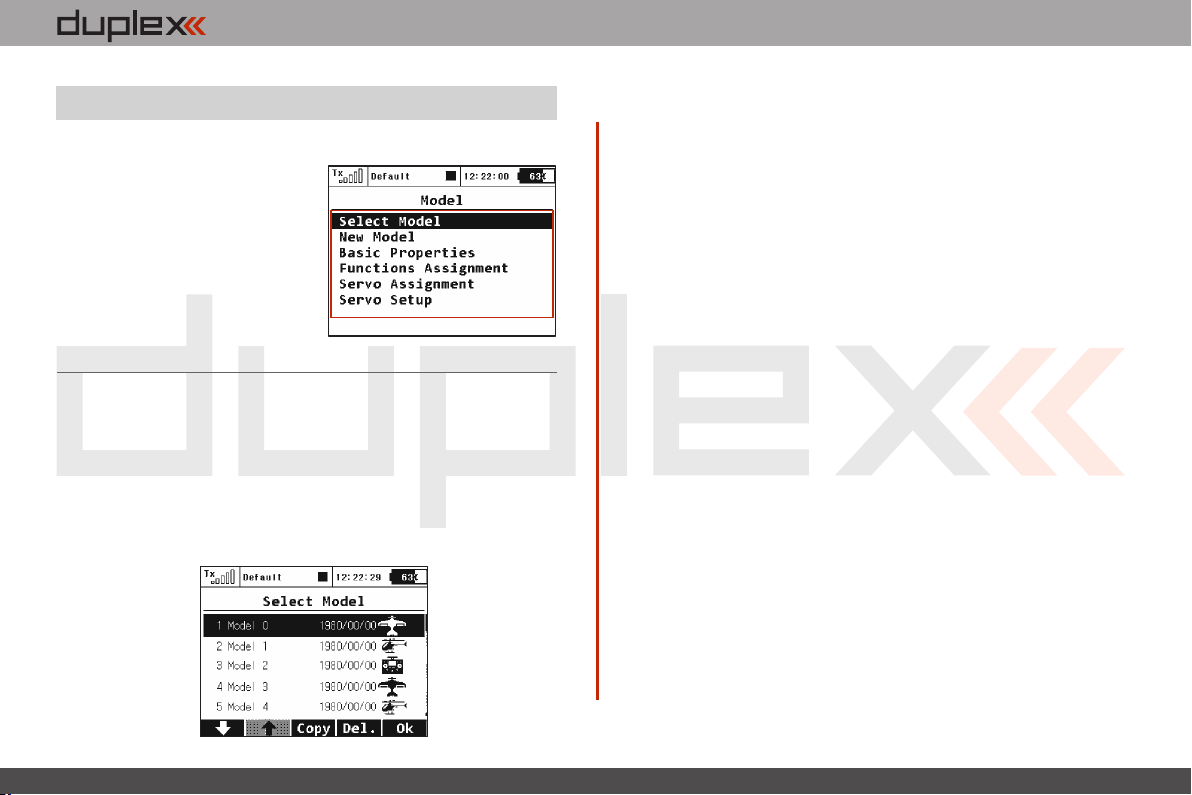
9.1. Model
The „Model“ menu contains basic functions for working with your
model, like:
• Select Model
• New Model
• Basic Properties
• Functions Assignments
• Servo Assignment
• Servo Setup
9.1.1 Model Selection
The menu displays a list of your models stored in the memory with
their names, setup dates and model types. The currently selected
model is marked by a check mark. In the menu you may select a
model and manage all of your models. You can copying models,
delete models (except for the currently selected model) and change
the storage sequence of your models.
1. Model selection
In the list of models, select the required model and confirm it by
pressing the „3D button“ or „F1(Ok)“ button. You will be prompted
to confirm loading of the selected model.
The DC-16 transmitter offers a „Model checking“ function, which
compares the series number of the receiver in the model profile with
the series number of the receiver with which it is starting to
communicate. If the two series numbers do not match, the
transmitter displays a warning that a different receiver has been
detected for the model. In this situation, you the user, will decide
whether to:
• Confirm the change – this assigns the new receiver to the
model.
• Reject the change – the transmitter will not communicate with
the newly detected receiver and model will not be switched on.
Select another model from the transmitter register.•
The information about receiver discrepancies will also be displayed
after the creation of a new model and binding or establishing
communication with the receiver.
Through the use of this function, if you choose, the new receiver will
be assigned to the given model for future checks.
2. Copying a model
The complete setup information of a model can be copied and used
to create a new model with the same programming. Select the
model from the model list that you want to copy and then create the
copy by pressing the „F3(Copy)“ button. You will need to edit the
name of your copied model before it can be saved. Once you edit the
4. 4.
Page 33
computer radio control system
EN
Note:
If you would like to make set-up changes in an existing
model, you should first make a copy of the original
setup. This will help you if you would like to return to the
original model setup.
name, press the „F5(Ok)“ button to continue. Your model copy will
appear at the end of your model list.
3. Deleting a Model
A model can be removed from the memory. In the model list select
the model you want to delete and press the „F5(Delete)“ button. For
safety reasons it is impossible to delete the currently selected model.
4. Choice of model sequence
The sequence of models can the changed by using the „F1()“ button
to move the selected model one position downwards or by using the
„F2()“ button to move the model one position upwards. The
transmitter allows storing of many models in the memory.
Note:
Try to arrange your most frequently used models at
the beginning of the model list in order to avoid having
to browse the whole list when selecting a model.
9.1.2 New Model
Selecting this menu item starts the new model creation assistant.
The assistant begins creating a new model profile as soon as you
select, „New model“. Howerver, the new model will only be created
after the confirmation in the last assistant menu, „Servo
Assignment“. Until you make the final confirmation the new model
is NOT created or stored in the memory.
The setup possibilities of the DC-16 transmitter are very extensive.
For simplicity, some of the possible adjustments are accessible only
for certain combinations of wing and tail arrangements,
aerodynamic brakes, landing gears and number of motors or
engines.
Notice:
For safety, start creating a model with the receiver in the model
switched-off. Be careful when handling electric models or servo
binding, where an improper linkage connection may cause
damage when power is applied. When handling electric models
it is safer to remove the propeller or disconnect the motor during
model creation and tuning.
1
2
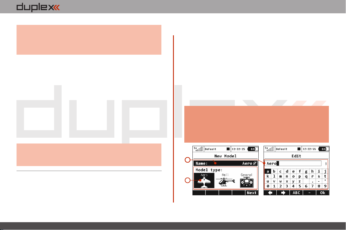
1. Model name
Use the „3D Control Selector“ to select the model name menu. You
4. 4.
Page 34
computer radio control system
Type
Description
0FLAP.|1AIL
Only one aileron servo
0FLAP.|2AIL
Two aileron servos
1FLAP.|2AIL
One flap servo, two aileron servos
2FLAP.|2AIL
Two flap servos, two aileron servos
2FLAP.|4AIL
Two flap servos, four aileron servos
4FLAP.|2AIL
Four flap servos, two aileron servos
4FLAP.|4AIL
Four flap servos, four aileron servos
EN
will enter the model name that you want the transmitter to use when
the model is stored in the transmitter‘s memory. The maximum
available space for a model name is 12 characters, including spaces.
When you select the „Name“ item the screen will change into the
„Edit“ menu, where you can use the „3D button“ to enter a name
for your model. Use the „F1()“ and „F2()“buttons to move the
cursor, if needed, within the name box.
Use the „F3(ABC)“ button to change between lower case letters and
capital letters.
Use the „F4()“ button to delete the character at the current cursor
position.
When you are finished editing your model’s name use the „F5(OK)“
button to confirm the name and return to the „New model“ menu.
The model name can be changed even after the model is stored by
going to: „Main menu->Model->Basic configuration“ and
selecting the model name.
2. Model type
The model type selection makes the setup of your model more
efficient by populating the menus with many of the popular options
for each type of model. The possible choices are: Aero, Heli and
General. Once your model is stored it is not possible to change that
model’s type.
Once your model’s name is entered and the type is selected, press
the „F5(Next)“ button to go to the next menu assistant step: „Basic
Properties“. The software will only allow this step if both the model
name and type have been set up.
9.1.3 Basic configuration- AIRPLANE
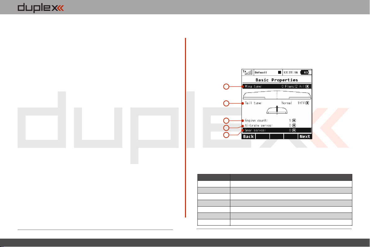
In this menu you will setup the wing configuration, tail type,
number of motor/engines, number of spoilers and number of
landing gear servos. Your model’s flight control functions are
generated according to your configuration choices in this menu and
the necessary fixed mixers become accessible.
1
2
3
4
5
1. Wing Type
The following wing type options are available:
4. 4.
Page 35
computer radio control system
Type
Description
Standard 1H1V
Standard tail assembly with one horizontal control
(elevator) and one vertical control (rudder)
V-tail 2H
Traditional V-tail
Ailvator 2H1V
Tail assembly with two elevator servos and one
rudder servo
Standard 2H2V
Tail assembly with two elevator servos and two
rudder servos
None – Elevon/Delta
The model is controlled by the combined control of
the wing surfaces
None
Model without a tail assembly
EN
2. Tail Assembly
The following tail option are available:
3. Number of Engines/Motors in the model
You can select the number of engines/motors in the model. You can
select up to 4 engines/motors. You can then assign the control of
each throttle to a different receiver channel if needed.
4. Number of Spoiler Servos in the model
You can select up to 2 spoilers servos. You can then assign the control
of each spoiler to a different receiver channel if needed.
5. Number of Landing Gear Servos in the model
You can select up to 4 landing gear servos. You can then assign the
control of each landing gear servo to a different receiver channel if
needed.
Press the „F5(Next)“ button proceed to the next step of the menu
assistant: „Functions Assignment“.
9.1.4 Basic Configuration - HELICOPTER
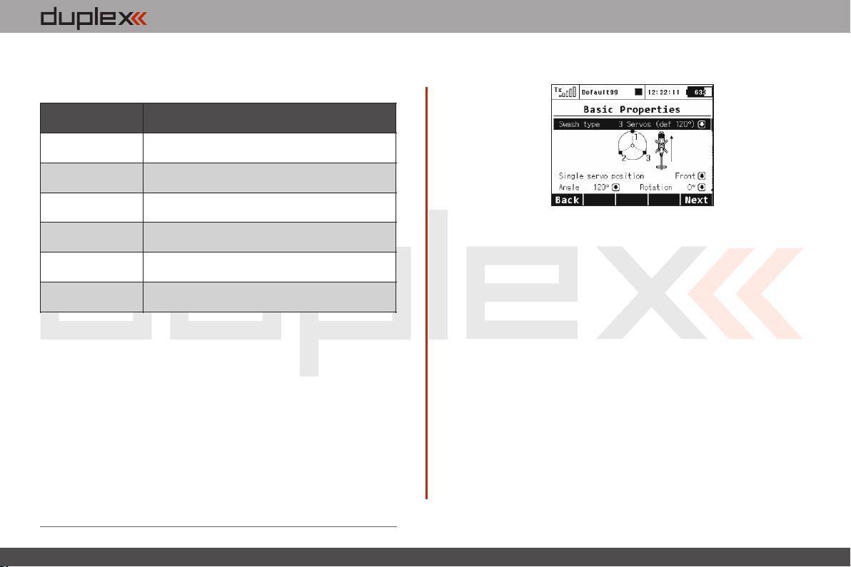
Swash Plate Type
Enter the type of swash plate your helicopter is using. Refer to your
helicopter’s manual if necessary.
• „3 servos (default 120°)“ – the swash plate controls the
elevator, aileron and collective pitch functions by coodinating three
servos. In the swash plate configuration, the servo control points can
be shifted closer to or farther away from each other around the main
shaft axis in 1° increments to help eliminate any unwanted
swashplate movement. You will also use this setting if your heli
requires a swash plate configuration of 3 servos (140°) or 3 servos
(90°).
Within this menu you can also change the effective swash plate
servo „lever lengths“ to compensate for any nonlinear servo arm
travel.
· „ 4 servos (90°) - the swash plate controls the elevator, roll
and collective pitch functions by coodinating four servos in 90°
orientation. You can make the same changes to this type as with the
swash plate described above.
4. 4.
Page 36
computer radio control system
EN
• „Mechanical“ - this swash plate type uses a single servo for
each flight function. This is the swash plate type to select if you are
using a flybarless controller.
Reverse swash plate orientation by 180°
The „Front servo position“ item is accessible only for the swash
plate type „3 servos (default 120°)“. If your helicopter requires, it is
possible with a single button to turn the swash plate configuration in
the setup by 180°.
Swash plate angle
The „Angle“ item is only accessible in the „3 servos (default 120°)“
swash plate type. The angle formed by swash plate points 1 - 2 and 1
– 3 can be configured by the user in 1° increments. This allows you to
fine tune your swash plate configuration as needed.
Rotation
The „Rotation“ Item is only accessible in the „3 servos (default
120°)“ and „4 servos (default 90°)“ swash plate types. This item
allows you to rotate the entire swash plate by a defined angle. This
allows you to add fine tune your swash plate as required by some
scale models.
Servo arm lengths (servo 1 – 4)
This item allows you move your swash plate control points either
closer to or farther away from the axis of rotation. This allows you to
compensate for any nonlinear servo movements.
Governor
In some helicopter setups a governor function is used for motor
control – this allows the motor to run at a constant speed
independantly from any collective pitch. If your model helicopter
setup includes a governor which can be controlled through the
receiver then switch on this function. once you enable this function,
the governor configuration becomes accessible in the „Fine
tuning/Gyro/Governor menu.
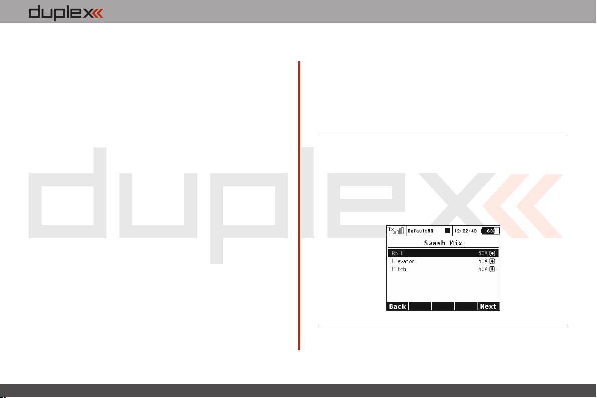
9.1.5 Swash mix
Here is where you set up the swashplate CCMP (=Cyclic/collective
pitch mixing) throws for Aileron, Elevator and Pitch. You can fine
tune each of these functions by changing their percentages. If
needed, you can reverse the throws by setting a negative
percentage.
4. 4.
Page 37
computer radio control system
9.1.6 Basic Configuration-GENERAL
EN
1
2
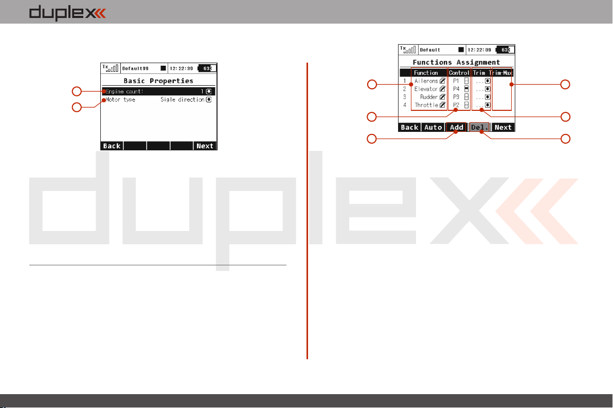
1. Number of Motors in the Model
This is where you select the number of motors in your model. It is
possible to select 0-4 motors. The number of transmitter control
outputs used to control the motors are automatically increased or
decreased according to number of motors that you select.
2. Motor Type
Do the motors in your model only turn in one direction or are they
able to rotate in both directions?
9.1.7 Assignment of functions
Based on your selected configuration a list of all flight functions will
be created with basic transmitter channel assignments.
The menu allows you to rename flight functions, assign a flight
function to any arbitratry transmitter stick, switch, knob or slider and
also allows you to setup additional flight function trims.
You can allow the software to automatically assign your flight
functions by pressing the „F2(Auto)“ button and then press the
„F5(Yes)“ button.
1
2
5 6
1. Flight function Renaming
By editing each „Function“ item you can rename a flight function
from its original name to any name that you choose.
2. Assignment of a Control Element to a Flight Function
By editing each „Control“ item you can assign any arbitrary stick,
switch, knob or slider to a given flight function. The proportional
channels 1 – 8 are marked P1–P8. The markings Sa-Sj designate
switches with the same designation as on the transmitter front
panel.
When you select one of these items you will enter the menu: „Select
control input“, see chapter 9.7. The assignments can easily be
verified by the graphic found beside the control element description
in the „Control “ section, which shows the actual setup of the
assigned control element.
3. Choice of an Additional Trim
The transmitter allows you to also create a trim function for any
arbitrary flight function. By editing one of the „Trim“ items you can
assign an arbitrary control element (stick, switch, knob or slider) to
control the trim of the selected flight function. When you select one
4
3
4. 4.
Page 38
computer radio control system
EN
of these items you will enter the menu: „Select control input“, see
chapter 9.7. The assignments can easily be verified by the graphic
found beside the control element description in the „Trim “ section,
which shows the actual setup of the assigned control element.
The trim functions for the gimbal sticks P1-P4 are automatically
assigned to the quad push-buttons located below the gimbals.
It is not necessary to assign them manually.
4. Range of Additional Trim
If you set up a trim function, you can use the „Trim-Max“ to set the
maximum trim influence on the given flight function. The default
value is 50%. If you set the value to 0% the trim control element will
not have any effect on the flight function at all. If you set a value of
100%, the trim control element will control the flight function to its
full travel.
5. Adding a Function
With the „F3(New)“ button you can create (add) your own flight
function.
6. Deleting a Function
With the „F4(Delete)“ button you may delete the selected flight
function.
Make sure that you have assigned all of your flight functions to the
correct transmitter control elements (stick, switch, knob or slider)
and make sure that the trims are assigned and functioning as you
wish. By pressing the „F5(Next)“ button you will enter the next
assistant step, the „Servo assignment “ menu.
Note:
The initial assignment is carried out in accordance with your
selected transmitter mode. If the initial assignment is incorrect
check the transmitter mode setup in the „Main menu->System>Configuration- >MODE 1-4 menu.
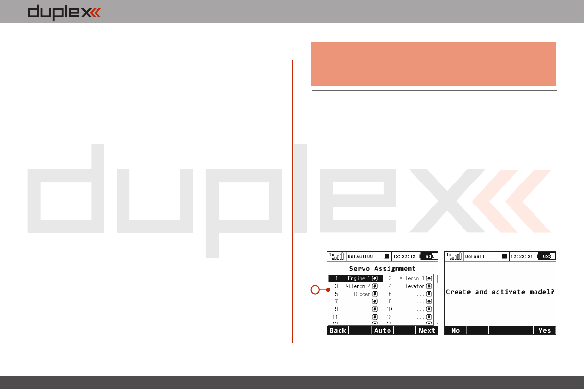
9.1. 8 Servo Assignment
This menu shows the assignment of transmitter output functions to
the receiver channels. This assignment can be changed as you wish.
The order number at the beginning of the column shows the
channel number and the assigned transmitter output function is
next to it. In this menu you can rearrange your output functions as
needed, i. e. any transmitter function can be assigned to any of the
receiver channels. The only restriction is the number of channels
which the transmitter can control (16 channels). The transmitter can
automatically set up your servo configuration based on your
previous model setup. If you want the transmitter to automatically
assign the servos in the same order as the last model that you set up,
press the „F3(Auto)“ button and then press the „F5(Yes)“ button.
a)
1
4. 4.
Page 39
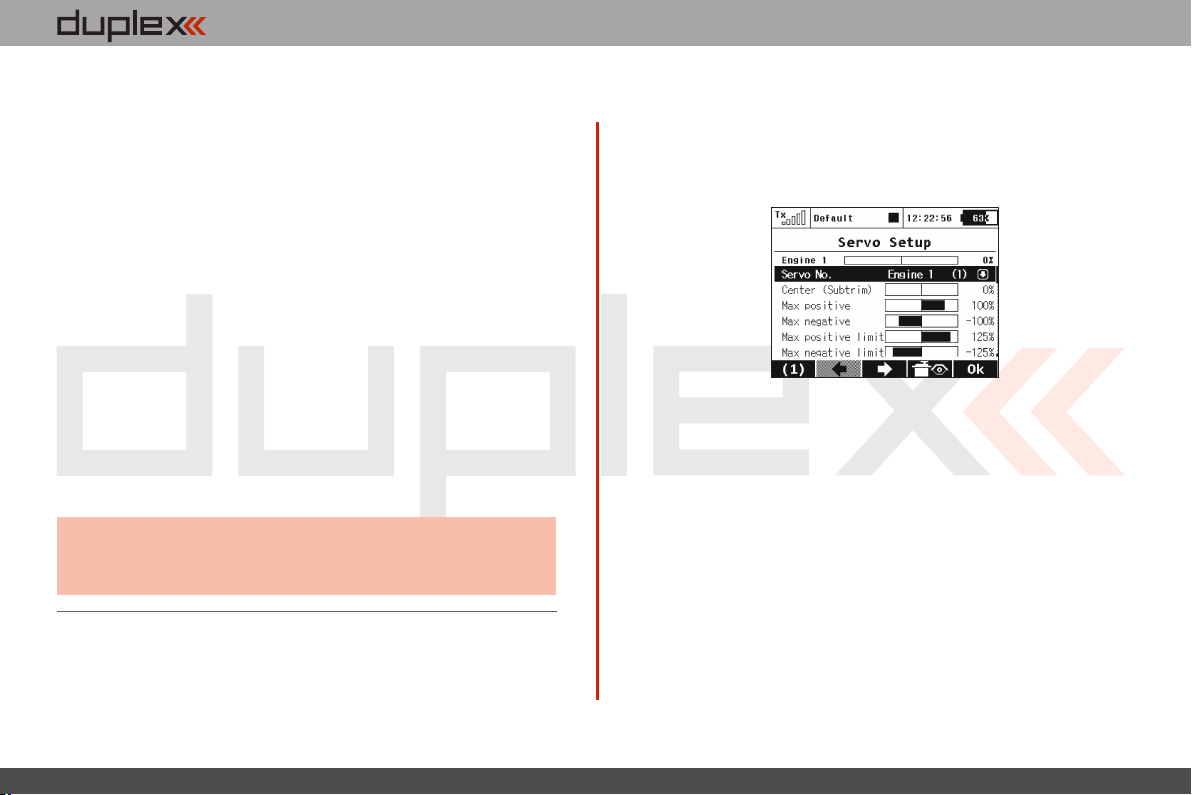
computer radio control system
EN
1. Assignment of Transmitter Output Functions to Receiver
Channels
Select the required receiver channel and press the „3D button“.
Now you can choose which function you want assigned to the
selected receiver channel.
With the „F5(Next)“ button you will enter the next step of the
assistant which creates and stores the model into transmitter
memory.
a) The assistant asks you to confirm the creation of the model by
displaying the question „Create and select a model?“. If you answer
by pressing the „F1(No)“ button, the model will not be saved and
you will return to the assistant to continue with further
configuration of your model.
If you press the „F5(Yes)“ button, the model will be stored in the
memory and at the same time will be activated. After that, you are
automatically taken to the „Servo Setup“ menu. Your stored model
can, of course, at any time be configured by selecting the „Main
menu->Model“> „Servo Setup“ menu.
Advice:
Once your model is created and activated you should
bind your receiver with the transmitter and then
proceed with „Servo Setup“.
9.1.9 Servo Setup
This menu is for the additional tuning of output functions of the
transmitter->receiver channels->servos. The assignment of a
transmitter output function to a receiver channel is shown in the
upper part of the menu (first item below the menu description).
1. Display of a Receiver Channel Throw
In the upper part of the menu the actual throw of the selected
channel is displayed using a live graphic. If you make a change to
your setup in this menu, you will immediately see how the output
will be influenced by the change.
2. Selection of Receiver Channel
In the first position F1 in the lower bar you see the actual selected
channel. With the F2() or F3()buttons or by editing the item „Servo
#“ you will select the receiver channel which you intend to
configure.
3. Center (Subtrim)
With this item you can adjust the servo neutral position of the
selected receiver channel.
4. 4.
Page 40
computer radio control system
Advice:
When building a model try to mechanically adjust the
neutral positions as perfectly as possible. If you are
going to use a high „Center (Subtrim)“ value in order to
set-up a servo neutral, the resulting servo throw will be
restricted.
4. Max Positive/Max Negative Throw
This item sets the useable end points of the transmitter output
function, i.e. how far the transmitter control element can move each
surface. This functon is used to set your maximum control throws for
flight and to limit any potential binding of a linkage or surface. This
limit can be exceeded by the use of mixes or combined functions.
Note:
The size of the maximum throw can influence trim
settings, dual rate throws and other proportional
setups.
5. Max Positive/Max Negative Limit
These restrict the absolute throw of the receiver channel output.
This limit can never be exceeded by any combination of functions or
mixes.
EN
6. Servo Reversing
Use this item to reverse the direction of a servo’s travel.
7. Delay of positive/negative
This item allows you to delay the servo channel‘s travel time
between both end points. This can be defined for the positive and for
the negative value (each travel direction). For instance, the opening
of a landing gear can be slower, than when it retracts.
Advice:
This function is great for timing retract gear servos.
Advice:
You can adjust the throw limit to prevent a surface or
linkage from hitting a mechanical stop or to prevent the
servo from over-driving its mechanical throw range.
This allows you to prevent mechanical servo damage.
4. 4.
Page 41
computer radio control system
EN
9.2. Fine Tuning
9.2. Fine Tuning
- Extended program functions for fine tuning your models
• Flight Modes
• Digital Trims
• Flight Mode Trims
• Dual Rate/Expo
• Function Curves
• Aileron Differential (This menu is only accessible in the wing configuration
0FLAP│2AIL and higher)
• Free Mixers
• V-Tail (This menu is only accessible in the „V-tail“ tail configuration.)
• Butterfly (This menu is only accessible in wing configuration 2FLAP│2AIL and
higher)
• Ailevator (This menu is only accessible in the „Ailevator“ tail configuration)
• Delta/Elevon ( This menu is only accessible in wing configuration „None-
Elevon/Delta“)
• Gyro/Governor (Helicopters only)
• Throttle Limiter(Helicopters only)
9.2.1 Flight Modes
The purpose of programming Flight Modes is to provide the ability
to activate a group of settings that will optimize your flight control of
your model. Flight Modes can just as easily represent settings for
Take Off, Soaring, Landing and much more. They can be used in any
particular situation where different settings of basic flight
parameters is desirable. The DC-16 gives you the advantage of a
wide variety of programing options.
Up to 10 different flight modes are available for every single model.
Each one of these flight modes can be named differently for instant
recognition. Only one of the flight modes can be active at any given
time. With a little practice you will discover that creating your flight
modes in logical order can prevent confusion in a critical situation.
Flight mode control can be assigned to any of the switches, sticks, or
knobs of the transmitter.
Flight Mode Configuration
• Some of the configuration settings come in two options. G-
global (globe symbol) and S-Separate. Switching from G to S, system
let you set up each flight mode individually.
Warning:
When you switch from Global to Separate settings; all
values will be copied directly to existing flight modes.
• If the flight mode configuration is set to S, each flight mode’s
values can be set independently from the other flight modes. When
you switch to different flight modes the pre-set position of an output
(a control surface, for example) can be changed to optimize the
control system of your model.
• Also, if the flight mode configuration is set to S, different
variables for each function can be assigned to each flight mode. The
assigned control switch can control multiple values within each
flight mode.
• After creating a flight mode, this will become system wide
settings for all future models.
4. 4.
Page 42
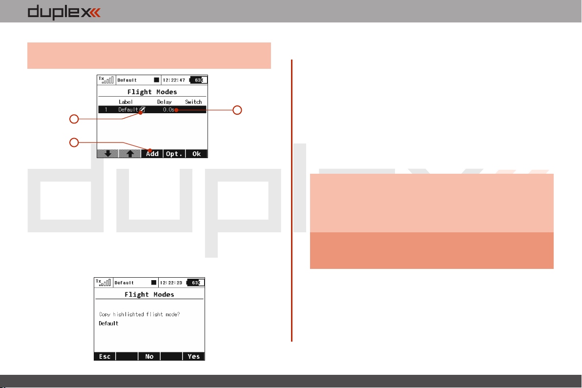
computer radio control system
EN
Advice:
If no flight mode is required, do not change the pre-set
configuration.
2
1
Adding Flight Modes1.
Pressing the “F3 (Add)” button creates a new flight mode. Simply
highlight existing mode and press “F3 (New)” button. A copy
confirmation menu appears on the screen, use the function keys to
continue.
Press the “F5 (Yes)” button to create copy of the existing flight
mode.
Press the“F3 (No)” button to create a new flight mode.
Press the“F1 (Esc)” button to be taken to main flight mode menu
screen.
3
Naming Flight Modes 2.
We recommend naming flight modes according to their function, for
example: Take Off, Soaring, Autorotation….
Flight mode names/labels can be easily edited at any time.
3. Flight Mode Delays
The time delay function can help smooth the transition from one
flight control state to another. Sudden changes in the positions of
your control surfaces can negatively affect performance or even
create a critical situation. The Time delay can help you avoid this
situation.
Advice:
If the desired result is not already tested or fully known
(maiden flight), always make sure that you have set
enough time delay for all of the changes to be
implemented and that you have plenty of time to
properly respond.
Warning:
4. Flight Mode Activation
A flight mode ca n b e a ctivated by any control de vice
(Switch/Knob/Stick). When you select a switch and by editing its
desired assignment you can activate and pick the position at which
this Switch/Knob/Stick or Logical Switch will turn flight mode ON or
OFF (see chapter 9.7). You can use the visual indicator in the switch
Throttle hold is not affected by the time delay. This
function will always be performed instantly.
4. 4.
Page 43
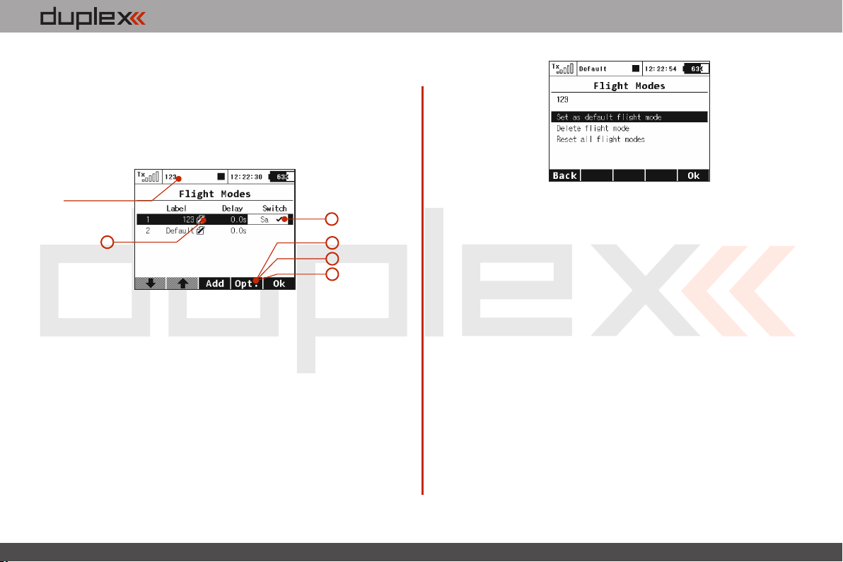
computer radio control system
column to help you determinate the ON or OFF switch position for
each flight mode.
• Check Mark – ON Position
• X Mark – OFF Position
When the flight mode is activated the flight mode name can be seen
the top of the desktop screen.
Name of the
current flight mode.
4
5
Flight Mode Activation Priorities5.
If you have created multiple flight modes that can match a given
flight condition but that vary in their specific details (Landing in
strong or light wind). You can create the order in which those modes
can be turned on. The Numeric order will determine your priorities.
A lower number equals a higher mode priority. The initial flight
mode has always the lowest priority.
6
7
8
EN
6. Flight Mode Default and Reset
Any of the created flight modes can be pre-set as a future default.
Simply highlight your choice and press the “F4 (Opt.)” button to see
confirmation menu. Pick the, “Set as a Default Flight Mode” option
and the flight mode is now set as your new default.
7. Deleting a Flight Mode
To delete a flight mode:
Highlight the desired flight mode and press the “F4 (Opt.)” a)
button to see the options menu.
Scroll and select the “Delete flight mode” option and press the b)
“F5 (OK)” button to make the final confirmation.
The initial flight mode is set as a default and can not be deleted.
8. Flight Mode Reset
All of the flight modes can be reset to basic settings at the same time.
Simply highlight any flight mode and press the “F4 (Opt.)” button
then use the “Reset all flight modes” option to reset all flight modes
to their basic settings. All previous changes will be deleted and the
flight modes will be reset to the G (Global) setting.
4. 4.
Page 44
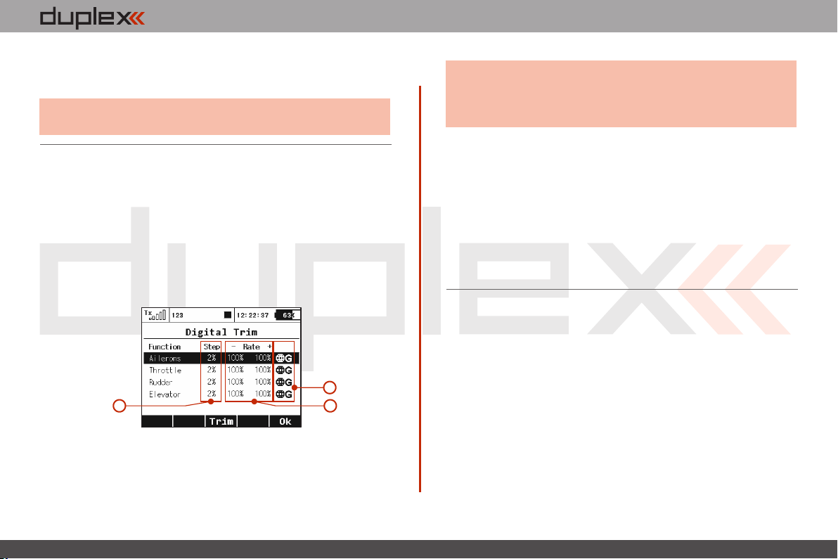
computer radio control system
EN
This is useful when you are setting up a new model from a copied
model and you want different flight modes.
Advice:
After you make a configuration change or perform a
reset, always check all flight modes.
9.2.2 Digital trim
Fully programmable digital trims are located right under transmitter
gimbals as a set of four directional buttons. All adjustments and step
changes are made in the “Digital Trim” menu. You can assign
different trim ranges and trim steps to every trim control function.
The “F3 (Trim)” button switches your desktop display to the main
trim screen where you can instantly observe your setup changes.
3
1
1. Digital Trim Programmable Steps
Trim step changes are made in the “Step” menu column, a larger
percentage number equals more movement with each press of the
trim button.
2
Advice:
For a maiden flight we recommend using larger trim
steps. After familiarizing yourself with your model’s
behavior you can switch to smaller steps for finer
trimming.
2. Trim Range
Trim range changes are made in the“Rate” menu columns which
show the trim’s percentage of possible travel. Both negative and
positive travel can be adjusted individually.
3. Global or Separate Trim Setting
The trim configuration for all main functions can be set collectively
for all flight modes by keeping the “G (globe symbol)” setting or they
can be set in each flight mode individually by selecting the “SSeparate” setting.
9.2.3 Flight Mode Trims
This menu allows you to set the function output position (if needed)
for each flight mode individually. For example: if your elevator
needs to be raised in one of your flight modes but not the others.
Each function output can be set either globally or separately.
1. Servo Position
A transmitter output channel can be assigned to more than one
receiver output channel if needed. Adjusting the values in the
individual columns marked “S1-S4” will change the position of the
servo (surface) for each output function. The servo position is
displayed as a percentage of the total servo travel.
Pressing the “F3 (Clr)” button resets the highlighted line’s travel
values to 0%.
4. 4.
Page 45
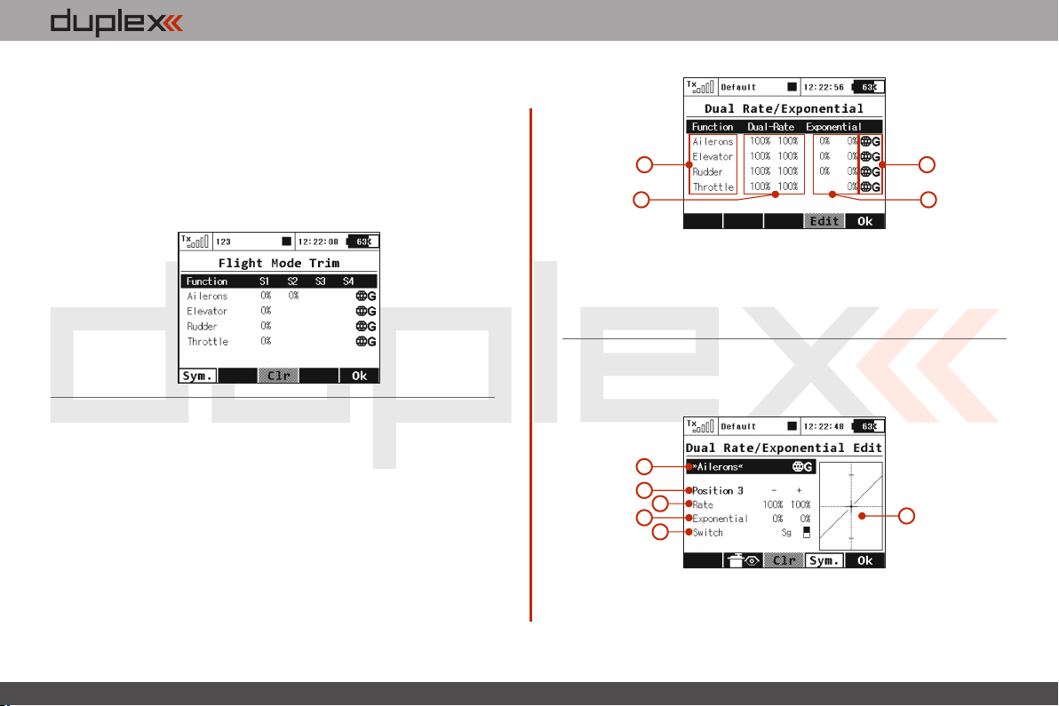
computer radio control system
Pressing the “F1 (Sym.)” turns ON/OFF the lock which allows each
output to be adjusted either together (symmetrically), or
independantly.
2. Trim Travel Global or Separate Setting
The servo trim position for each function output can be set either
collectively for all flight modes by selecting the “G-(globe symbol)”
or individually for each separate flight mode by selecting “S-
Separate”.
9.2.4 Dual Rate/Exponential
This menu allows you to set up dual or triple rates for any of your
created output functions. Any of the channels can be set with
dual/triple rates and custom exponential settings. Exponential
settings can significantly increase your control precision by making
your stick movements (around center point) yield less control
movement. At the same time, the end points of the control surface
throw can be set to its extremes.
EN
a
b
Channel namea)
Dual/Triple rate travel settingb)
Exponential settingc)
Global or separate flight mode settingd)
By highlighting one of the channels and either pressing the “F4
(Edit)” button or by pressing the “3D Control” button you will
access the individual control‘s settings page.
a
b
c
d
e
Channel name and global/separate settinga)
Current switch positionb)
d
c
f
4. 4.
Page 46
computer radio control system
EN
Percentage of travelc)
Exponential rate settingd)
Assignable switch optione)
Graphic interfacef)
1. Expo Global or Separate Setting
Expo configuration for all channels can be set collectively for all
flight modes by selecting the “G-Global (globe)” symbol or you can
allow individual expo settings in each separate flight mode by
sellecting the “S-Separate” symbol.
2. Expo/Dual Rates Switch Assignment
By selecting “Switch Option” you will access the“Select Input (e)
Control” screen where you can select the control element that you
wish to control the dual rate and/or expo for the selected function.
For simple dual rates; a 2-position switch is sufficient. For more
complex triple-rates; any 3-position switch or one of the fully
proportional channels can be selected. After your selected switch
has been assigned. While the “Select Input Control” screen is still
visable you can change the switch travel by using “F2 (Prop.)”
button to select the proportional setting. The correct function can
be verified in the “Dual Rate Edit” screen by activating the switch
and observing the position number change to “Position 1-2” for a
two position switch or, if 3-position switch is used, to “Position 1-23”. For a 3-position switch you will also need to use the „F1 (Centr)“
button before all three positions will be correctly displayed.
Expo/Dual Rates Travel Setting 3.
Every switch position can define a different function and (b)
exponential value. Any change made to the settings can be directly
observed on graphic interface .(f)
Dual/Triple rate setting is defined by percentage of the travel . A (c)
higher number increases travel, a lower number decreases travel.
Expo rate is defined by percentage of the function curve Zero (d).
rate represents linear function. As expo rate increases linear travel
changes to exponential “curve” travel.
Exponential and Dual rate settings combined with flight modes
create virtually unlimited customizability.
Advice:
For smooth, precise flight we highly recommend setting
up exponential and dual rates.
4. 4.
Page 47
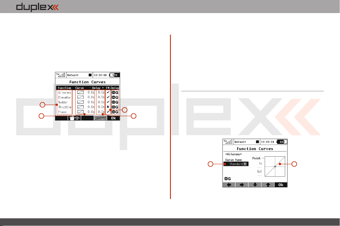
computer radio control system
EN
9.2.5 Programmable Function Curves
Function curves define the relationship between the actual position
of your stick/switch/knob and the position of the servo. This screen
displays the menu of all assigned functions , graphic interfaces (a)
(b) (c), and programmable time delays . All adjustments can be
visually inspected right away in the servo monitor page by pressing
the “F2 (Servo)” button.
a
b
a) Function name.
Graphic interfaces.b)
Time delay.c)
Global or Separate setting.d)
e) Flight Mode Delay Enable
Flight Mode Delay Enable
In the menu Fine Tuning->Function Curves, it is possible to
activate/deactivate a delay for a specific function while switching
between flight modes. Specifically, in the picture, it is the 5th column
(FM. Delay) that allows this. The activation of a delay also might be
flight-mode specific (i.e.: in first flight mode the delay is activated
e
c
and in the second mode it is disabled). There are some specific
conditions where setting this option for one function has an effect in
another function.
• If V-Tail is selected, the option influences both rudder and
elevator.
• If Delta wing is selected, the option influences both elevator
and aileron.
• If electronic heli swash mix is selected, the option influences all
functions of the swash plate (roll, pitch, and elevator).
1. Programming Function Curves
The Function Curves programming screen can be accessed by
highlighting “Curve” window and pressing “3D Control” button or
directly accessed by simply pressing “F4” button. Either way, you will
be taken to the highlighted function’s curve option screen.
a
a) Function curve type.
b) Graphic interface.
b
4. 4.
Page 48
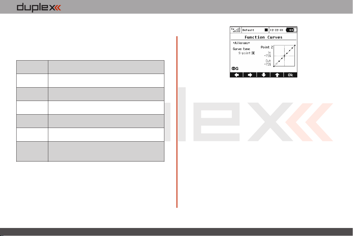
computer radio control system
Standard
Linear values, set In/Out point
Constant
Constant value, set point
3-Point, x>0,
x<0, |x|
3-Point curve, set value for 3 points
5-Point
5-Point curve, set value for 5 points
7-Point
7-Point curve, set value for 7 points
9-Point
9-Point curve, set value for 9 points
+Pos, - neg,
+-Symmetrical
4-Point end to end curve, set value for 4 points
The function curve can selected from the existing list or from
custom, previously modified options.
Available Options:
1. Function Curve Setting
You can select the function curve which best fits your application.
You can choose one of the pre-programmed 3-9 point ones or select
any of custom symmetrical curves.
You can edit a function curve from inside the graphic interface by
moving the displayed control points.
EN
All of the points can be moved in both horizontal and vertical
directions. Using the “3D Control” or the “F3” and “F4” buttons you
can move the curve points in a vertical direction and in a horizontal
direction by using the “F1” and “F2” buttons.
By pressing the “3D Control” button you can switch between the
individual curve points. Pressing the “Esc” function will return you to
the previous control point. On the left side of the graphic interface
you will see the percentage representation of your selected control
point’s position. “In” and “Out” percentage numbers represent
actual input and output position of a given control point.
2. Function Curve Delay
The time delay function can help smooth the transition from one
state to another. The function of the “Delay” is to slow down the
movement of a control surface in relationship to the position of the
stick. Example: a negative number “-” slows movement of the
rudder from moving right to left, a positive “+” number slows rudder
movement from left to right.
4. 4.
Page 49
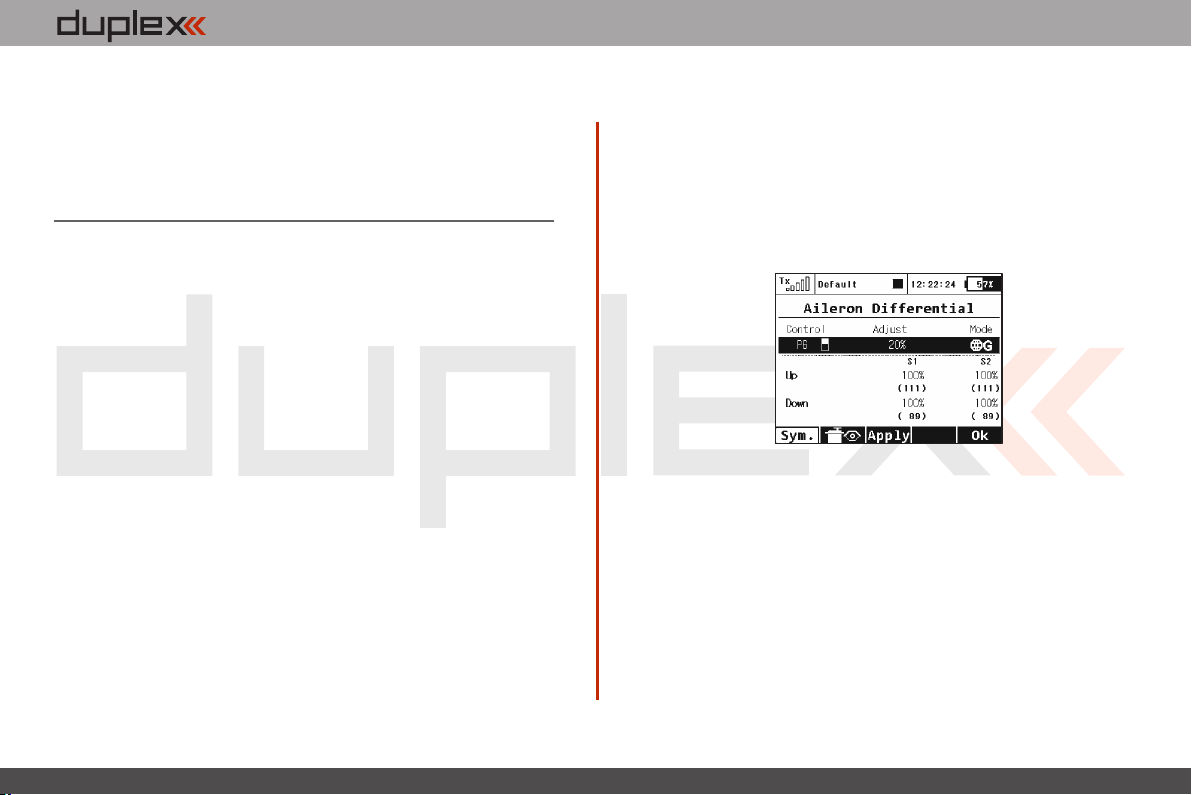
computer radio control system
EN
3. Global or Separate Function Curve Setting
The function curve configuration for all channels can be set
collectively for all flight modes by selecting the “G-Global (globe)”
symbol or you can set individual function curve settings in each
separate flight mode by sellecting the “S-Separate” symbol.
9.2.6 Aileron Differential
The aileron differential function reduces the downward travel of the
aileron(s) to help eleminate any adverse yaw tendencies in rolling
maneuvers. Semi-Symmetrical airfoils with an aileron in the down
position induce higher drag than when the aileron is in the up
position. Therefore, the aileron travel up and down has to be set
differently. The number of aileron servos displayed depends upon
the selected wing type of your airplane; the maximum number is
four “S1-S4”.
1. Aileron Differential Global or Separate Setting
The aileron differential for all channels can be set collectively for all
flight modes by selecting the “G-Global (globe)” symbol or you can
allow individual aileron differential settings in each separate flight
mode by sellecting the “S-Separate” symbol.
2. Aileron Differential Setting
All of the ailerons can have different travel ranges. The different
adjustments are displayed in columns marked „S1-S4”. The number
of servos in use is equal to the number of displayed setup columns.
The travel range for each servo can be set. Scroll and highlight either
the “Up” or “Down” menu line with “3D Control” button. Press the
„3D Control“ button to access and edit the settings for each servo. If
4. 4.
Page 50
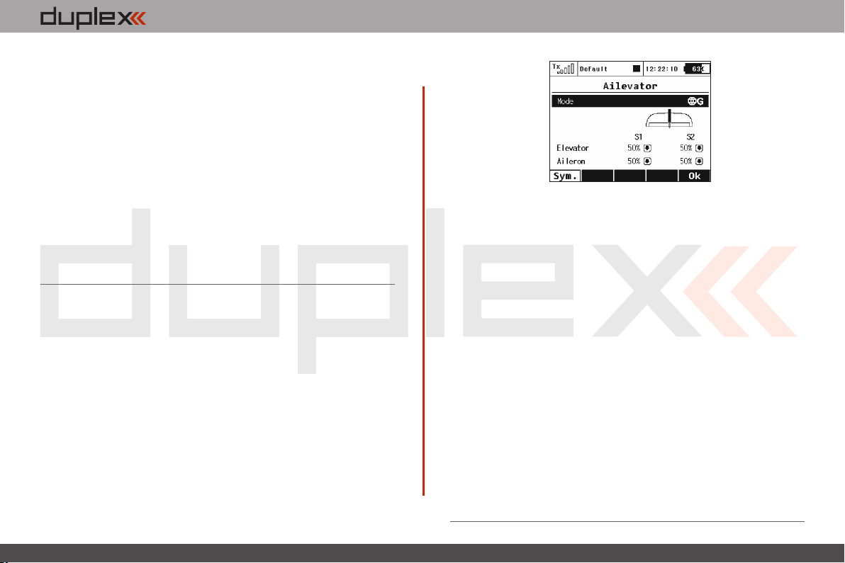
computer radio control system
the servos need to be adjusted independantly, use the “F1 (Sym.)”
button to unlock the servo travel for adjusting the individual values
in the selected menu line.
3. Tuning of Aileron Differential
You can now assign a proportional control and the adjustment rate.
When moving the control, the differential rates are updated
accordingly: up-rate is increased and the down-rate is decreased
depending on the adjustment rate and position of the control. In the
picture the real differential rates are enclosed in parenthesis.
The „F(3) Apply” button clears the adjustment rate and stores the
real differential values into the editable fields so that the control no
longer has any influence.
9.2.7 Ailevator Function
The ailevator function uses two servos for the elevator channel. Both
sides can be programmed to be controlled independently. With
ailevator function both servos can be mixed together with ailerons
and work in sync for better roll control. The Ailevator mix has to be
activated by choosing the “Ailevator2H1V” tail setting. Unless you
have previously chosen a different percentage for one of the tail
mixes, the initial settings for “Ailevator” function are 50% of the
elevator and aileron travels.
EN
1. Ailevator Global or Separate Setting
The Ailevator configuration for both channels can be set collectively
for all flight modes by selecting the “G (globe)” symbol or you can
set individual Ailevator settings in each separate flight mode by
sellecting the “S-Separate” symbol.
2. Ailevator Setting
Ailevator configuration has four different adjustable parameters.
The lines marked “Elevator” and “Aileron” contain two columns
“S1” and “S2” which represent the elevator and aileron surface
throws as a percentage. Scroll and highlight the lines marked as
“Elevator” or “Aileron” with the “3D Control” button and press the
“3D Control” button to access the individual setting of each servo. If
the servos need to be adjusted independantly, use the “F1 (Sym.)”
button to unlock the servo travel for adjusting the individual values
in the selected menu line.
4. 4.
Page 51
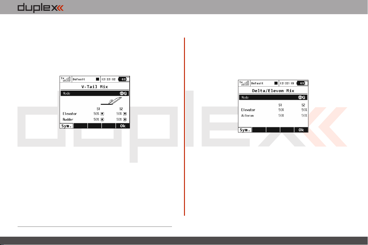
computer radio control system
EN
9.2.8 V-Tail Mix
If your model is equipped with a V-Tail, The two basic tail functions
(rudder and elevator) are mixed to control the tail of the airplane.
The V-Tail mix has to be activated by choosing the “V-Tail 2H” tail
setting. Unless you have previously chosen a different percentage
for one of the tail mixes, the initial settings for “V-Tail” function are
50% of the rudder and elevator travels.
1. V-Tail Global or Separate Setting
The V-Tail configuration for both channels can be set collectively for all
flight modes by selecting the “G (globe)” symbol or you can set
individual V-Tail settings in each separate flight mode by sellecting the
“S-Separate” symbol.
2. V-Tail Setting
The V-Tail configuration has four different adjustable parameters. The
lines marked “Elevator” and “Rudder” contain two columns “S1” and
“S2” which represent the elevator and aileron surface throws as a
percentage. Scroll and highlight the lines marked as “Elevator” or
“Rudder” with the “3D Control” button and press the “3D Control”
button to access the individual setting of each servo. If the servos need
to be adjusted independantly, use the “F1 (Sym.)” button to unlock the
servo travel for adjusting the individual values in the selected menu line.
9.2.9 Delta/Elevon Mix
The Delta/Elevon Mix uses two servos for the control of both the
elevator and aileron functions. This mix is most commonly used for
Delta type aircraft. The elevon mix has to be activated by choosing
the “None – Elevon/Delta” tail setting. Unless you have previously
chosen a different percentage for one of the tail mixes, the default
settings for the “Delta/Elevon” function are 50% of the aileron and
elevator travels.
1. Delta/Elevon Global or Separate Setting
The Delta/Elevon configuration for both channels can be set
collectively for all flight modes by selecting the “G (globe)” symbol
or you can set individual Delta/Elevon settings in each separate
flight mode by sellecting the “S-Separate” symbol.
2. Delta/Elevon Setting
Delta /Elevon confi guration has four different adjustable
parameters. The lines marked “Elevator” and “Aileron” contain two
columns “S1” and “S2” which represent the elevator and aileron
surface throws as a percentage. Scroll and highlight the lines
marked as “Elevator” or “Aileron” with the “3D Control” button and
press the “3D Control” button to access the individual setting of
4. 4.
Page 52
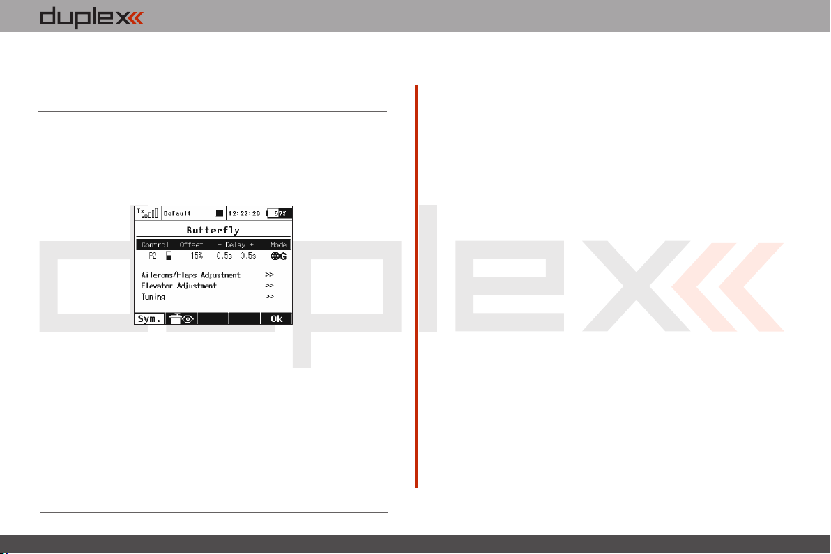
computer radio control system
EN
each servo. If the servos need to be adjusted independantly, use the
“F1 (Sym.)” button to unlock the servo travel for adjusting the
individual values in the selected menu line.
9.2.10 Butterfly Mix (Crow Mix)
The basic configuration of the butterfly mix (also known as crow) is
created by using ailerons, flaps, and elevator flying surfaces. The
Butterfly/Crow mix is helpful for maintaining speed during fast
descends and creating controlled drag for spot landings.
1. Butterfly/Crow Activation
The Butterfly mix can be activated by any control element
(Switch/Knob/Stick). By selecting the switch and by editing the
desired assignment you can activate and select the position at which
this Switch/Knob/Stick or Logical Switch will turn the Butterfly mix
ON or OFF. This menu line includes a visual graphic to show the ON
or OFF position of your selected switch.
2. Butterfly/Crow Delay
The time delay function can help smooth the transition from one
state to another. Function of the “Delay” is to slow down the
movement of the control surfaces during the change. Increasing the
number on the positive side “+” slows the deployment while
increasing the number on the negative side “-” slows return of the
surfaces to their original positions.
3. Butterfly/Crow Global or Separate Setting
The Butterfly/Crow mix configuration settings can be set collectively
for all flight modes by selecting the “G-(globe)” symbol or you can
allow individual aileron differential settings in each separate flight
mode by sellecting the “S-Separate” symbol.
4. Butterfly/Offset
Due to the request of many sailplane pilots this function was
updated. Now expanded to four screens, there are several added
options in this menu.
a. You can set an offset to the butterfly control so that there will be
a specified dead zone at the beginning of the control stick’s travel.
4. 4.
Page 53
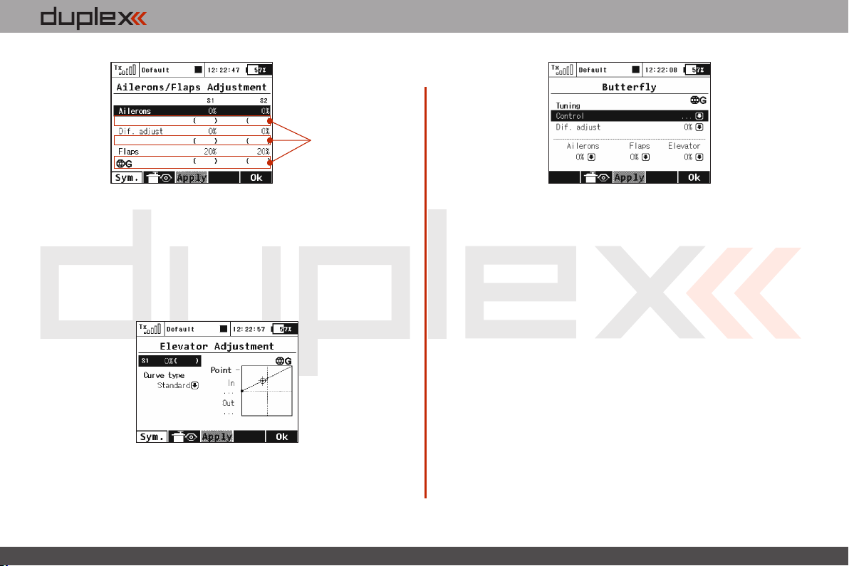
computer radio control system
Actual values of
airbra ke rates.
T h e v a l u e s
shown depend
on adjustments
m a d e i n
Butterfly Tuning
m e n u (see
below).
b. Ailerons/Flaps Adjustment
In the Ailerons/Flaps Adjustment menu you can set all the travel
needed for butterfly braking (for the flaps and ailerons). Also, you
can set a parameter called Diff. adjust which influences the aileron
differential. Positive values increase the upper travel of the aileron
servos, negative values increase the lower travel of the aileron
servos.
EN
d. Butterfly Tuning menu
Screen of the Butterfly menu allows you to fine tune all braking
travels through one proportional control (stick, knob or switch). The
values you set in this screen are added/subtracted to the
appropriate butterfly travels. The way these values influence servo
deflections depends on the position of the butterfly's control stick
and the position of the butterfly's Tuning control.
The „F(3)Apply” button operates similarly as in the Aileron
Differential menu. If you press this button, the values set in the
„Butterfly Tuning” menu are copied into the appropriate travels in
the „Butterfly Ailerons/Flaps/Elevator Adjustment” menu. After
that, all values in the Butterfly Tuning menu are initially set to zero (so
that the tuning control no longer has an effect).
c. Elevator compensation
The butterfly mixing is always from zero to the full stick position so
the curve is a little bit modified to control the whole travel range. You
can choose between a standard curve, constant and X-point curve
types.
4. 4.
Page 54
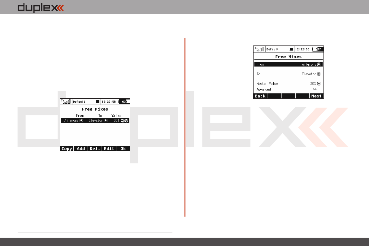
computer radio control system
EN
9.2.11 Free Mixes
The Free (programmable) mixes are used to make a second or „slave“
channel react as a result of the original channel’s input or by moving
any Switch, Knob or Stick. Any of the channels can be (Freely) mixed
with any other function, assignment or logical switch. Up to 20 free
mixes can be programmed for any given model. The primary
channel (“Master/From”) specifies the control or input function,
while the channel that reacts to the Master is called the “Slave/To”
channel. The “Master Value” represents the percentage of „slave“
channel travel output performed when the „Master“ channel
function is used.
1. Copying a Free Mix
Highlight an existing free mix and use the “F1 (Copy)” button to
create a copy of the existing mix.
2. Creating a Free Mix
Use the “F2 (Add)” button to create a new free mix. The Primary
channel called “Master/From” specifies the input function, while
the channel that reacts to the Master is called the “Slave/To”
channel. The last variable on the screen is the “Master Value” which
represents the percentage of the slave channel’s mix/travel. After
your model‘s basic configuration is finished, use the “F5 (Next)”
button to exit the free mix screen. If you need to make any changes
simply highlight the desired free mix and press the “F4 (Edit)”
button to reach the advanced settings menu for that free mix.
a). Free Mix Setting
The free mix configuration settings can be set collectively for all
flight modes by selecting the “G-(globe)” symbol or you can allow
individual free mix settings in each separate flight mode by
sellecting the “S-Separate” symbol.
b) Free Mix Activation
A free mix can be activated by any Switch/Knob/Stick. By selecting
“Switch” and by editing the desired assignment you can activate
and choose the position at which this Switch/Knob/Stick or Logical
Switch will turn the mix ON or OFF or even control its throw
proportionally. This menu line includes a visual graphic to show the
ON or OFF position of your selected switch. If you do not select any
switch then the mix is always ON.
c) Free Mix Curve Programming
This programming screen can be accessed by highlighting the
“Curve” item and by either using the “3D Control” button or by
pressing the “F4 (Curve)” button. By accessing the “Mixer Curve”
function screen you can select the mix curve which best fits your
application.
4. 4.
Page 55
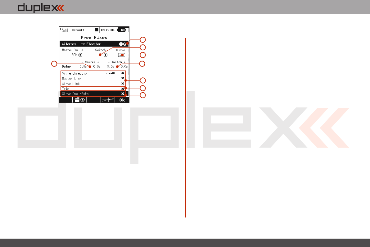
computer radio control system
a
b
c
d
d) Free Mix Deployment Delay
The time delay function can help smooth the transition from one
state to another. Values adjusted in the “Source” item will slow
down full mix deployment when the mix is ON (switched ON or
always ON) and the master channel master channel changes its
value. In this item, when you add a delay to only one side (- or +), the
mix deployment will be slow in one direction only (-100% to 100%)
or (100% to -100%). When you add a delay to both the negative (-)
and the positive (+) sides then your mix will be slowed in both throw
directions.
e) Free Mix Activation/Deactivation Delay
The „Switch“ values can only used when you have assigned a switch
to turn the mix ON and OFF. This delay operates independently from
the „Source“ values. The positive side of a delay is applied if the mix
is activated using Activation Switch. The negative side is used if the
mix is deactivated and both slow down any fast reactions while
turning the mix ON and OFF.
e
h
i
j
EN
f) Free Mix Multiple Servo Settings
If the mix uses more than one output function as the slave then the
“Output Mix” menu will appear. This menu allows you to edit the
settings for the individual slave servos (S1-S4).
g) Free Mix Directional Positive/Negative Movements
Once the free mix function is created you can edit the advanced
settings menu so that the mix will either add to or reduce a slave
function‘s movement. To do this, you can set the mix value as a
positive percentage or a negative percentage.
h) Using Another Free Mix to control a Free Mix
A free mix can be controlled by just a control input function (Master)
or it can also be controlled by another free mix’s control function
(Slave). Here is how to create a free mix who’s input is controlled by
an existing free mixer output:
• To allow a free mix to control another free mix you must enable
the “Slave Link” option. This allows the free mix to act as input for
other free mixes. Use the “3D button” to highlight and select this
option. You will see a check mark if the option is enabled and an X if it
is disabled. You will also use the (+) or (-) to determine the mix
direction.
• To allow a free mix to be controlled by another mix you must
enable the “Master Link” option. This allows the free mix to accept
the input from other free mixes. Use the “3D button” to highlight
and select this option. You will see a check mark if the option is
enabled and an X if it is disabled. You will also use the (+) or (-) to
determine the mix direction.
4. 4.
Page 56
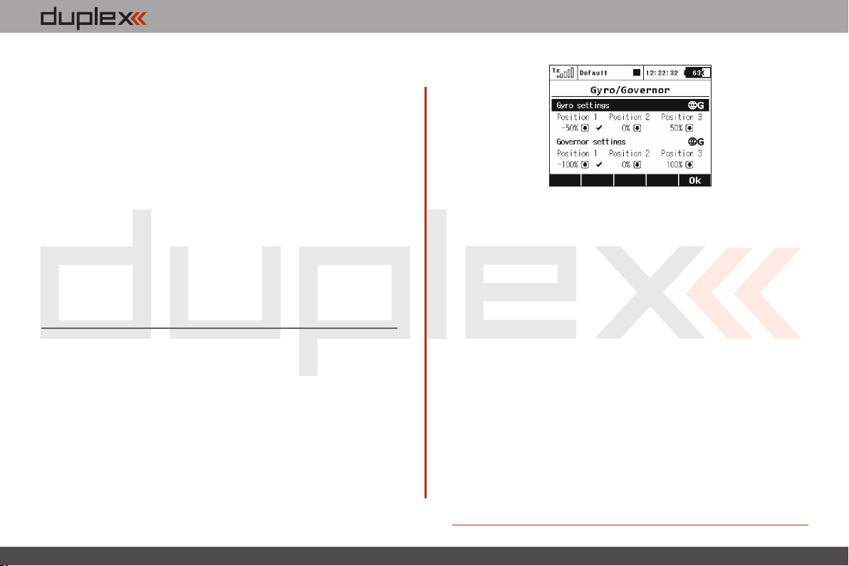
computer radio control system
i) Free Mix Trim Settings
This item allows you to enable or disable whether trim functions will
influence the free mix or not.
j) Free Mix Control by Dual Rates
With this item you can activate or deactivate the “Slave Dual-Rate”
function for the free mix. This settings allows the slave output to be
affected by dual rate inputs. All adjustments can be visually
inspected right away in the servo monitor page by pressing the “F2
(Servo)” button. Pressing the “F5 (Ok)” button returns you back to
free mix screen.
3. Deleting a Free Mix
Press the “F3 (Del)” button to delete the highlighted free mix.
4. Configuration & Setting
A free mix programming screen can be accessed by highlighting the
selected mix and then pressing the “F4 (Edit)” button.
9.2.12 Governor/Gyro
Typically, a gyro is used to stablize a model helicopter along its
vertical axis (rudder). One channel is reserved so that you may adjust
the gyro sensitivity (gain) from the transmitter. Also, a separate
channel can be reserved for the control of a throttle governor. The
governor can be enabled when you create the model or later from
the „Model >Basic Properties“ menu. This menu allows you to
adjust the settings for both of these output channels. The
Governor/Gyro settings can be set collectively for all flight modes by
selecting the “G-(globe)” symbol or you can allow individual
Governor/Gyro settings in each separate flight mode by sellecting
the “S-Separate” symbol.
EN
1. Gyro Settings
By default, the gyro sensitivity is assigned to the three position „Si“
switch. This allows you to have three different settings (Position 1,
Position 2, Position 3) for the gyro sensitivity. You can always assign
this function to a different transmitter control element (knob, slider,
switch) in the „Model, >Function Assignment“ menu. The Gyro
settings can be set collectively for all flight modes by selecting the
“G-(globe)” symbol or you can allow individual Gyro settings in
each separate flight mode by sellecting the “S-Separate” symbol.
2. Governor Settings
If you have the governor function enabled, by default, the governor
sensitivity is assigned to the three position „Sg“ switch. This allows
you to have three different settings (Position 1, Position 2, Position 3)
for the governor sensitivity. You can always assign this function to a
different transmitter control element (knob, slider, switch) in the
„Model, >Function Assignment“ menu. The governor settings can
be set collectively for all flight modes by selecting the “G-(globe)”
symbol or you can allow individual governor settings in each
separate flight mode by sellecting the “S-Separate” symbol.
4. 4.
Page 57
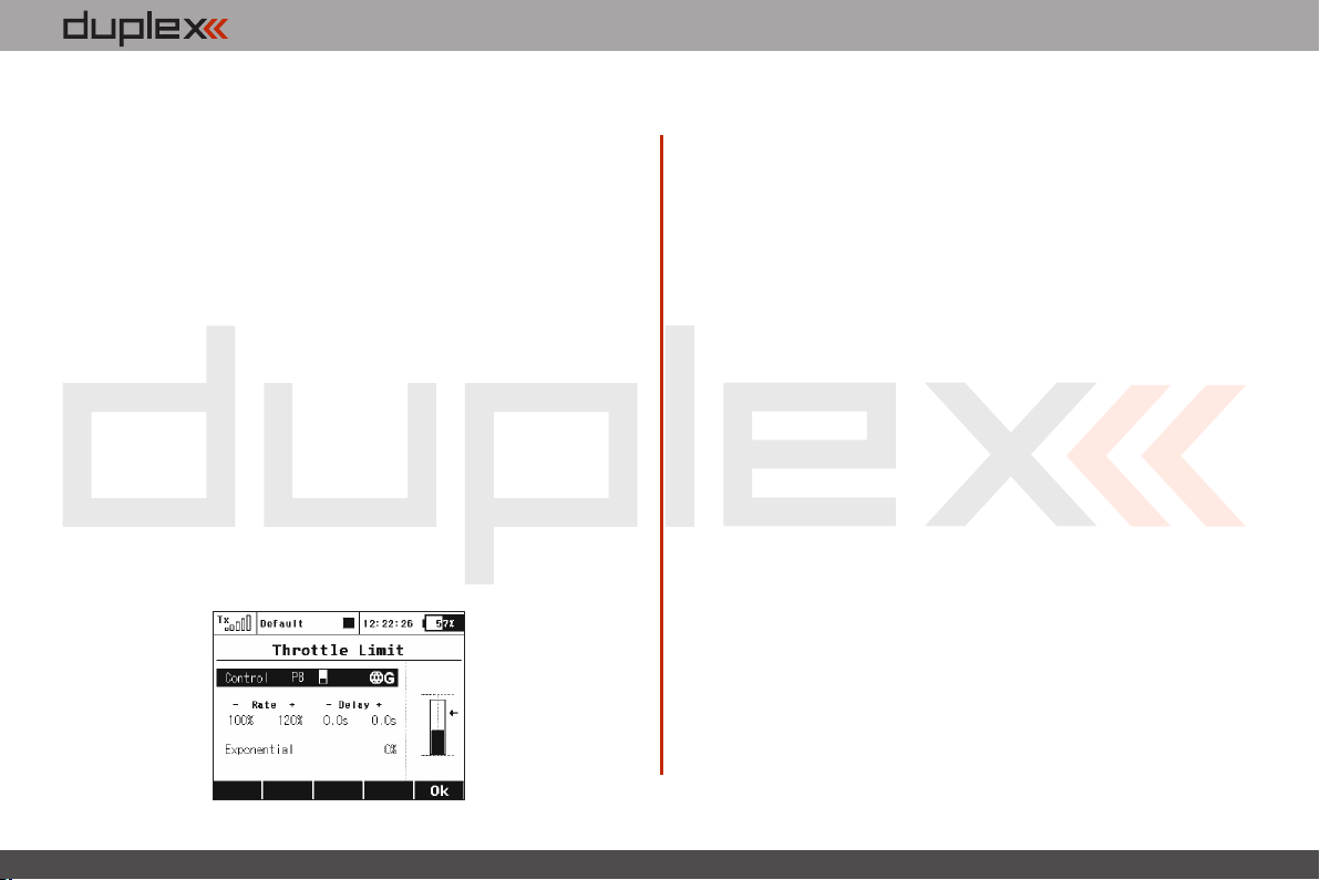
computer radio control system
EN
9.2.13 Throttle Limiter
If you have several flight modes and all of them have specific throttle
curves, the Throttle Limiter might help you to get the motor's RPM
safely from the lowest to the maximum RPM that is controlled by
your throttle curve.
You are free to choose any control device (proportional or a switch)
that will operate as a speed limiter. It doesn't allow the throttle to go
any higher than the position that this control shows. The limiter
operates within a specified range (negative and positive rate, “- Rate
+”). Using the “-” rate you can set the lowest motor RPM you want to
use. This is the point where the limiter begins its operation. The “+”
rate represents the maximum possible output of your throttle
channel. If your application needs full throttle, you should set the
“+” rate to a value higher than 100% so that the full throttle output is
not limited.
It is possible to set some delay for this control (if it is assigned to a
switch) so that the motor goes smoothly from low to high RPM (and
vice versa). Finally, the Exponential parameter enables you to finetune the output at lower RPM and the whole acceleration curve.
The throttle limiter also influences mixes where the throttle acts as
the source. The trim function is not influenced by the throttle limiter.
If a control device is not assigned, the throttle limiter function is
disabled.
4. 4.
Page 58
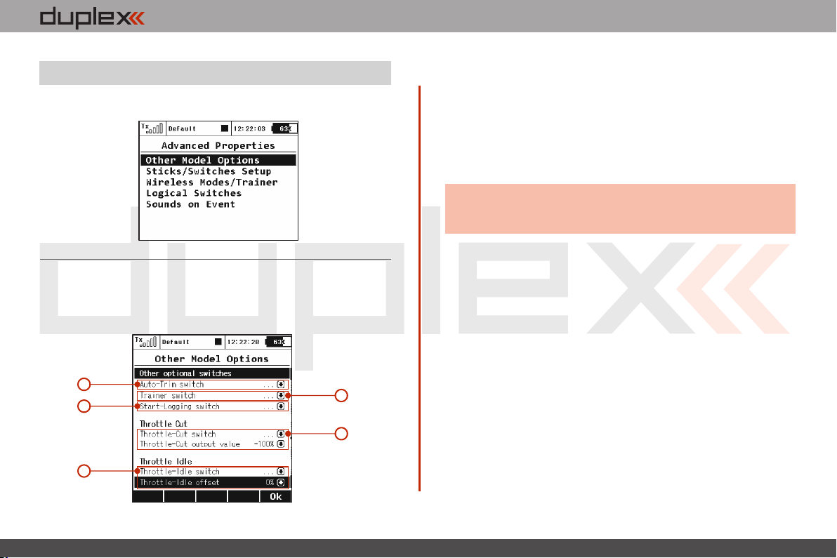
computer radio control system
EN
9.3. Advanced Properties
Advanced programming menu for DC/DS-16.
9.3.1 Other Model Options
This menu contains additional, special features of the DC/DS-16
transmitters.
1
3
5
2
4
1. Auto-Trim Function
Auto-Trim function can be activated using any assigned switch,
knob or stick. Once this function has been activated you can trim
your model using transmitter gimbals. The direction and speed of
the trim adjustment is determined by stick movement. Larger stick
movements equal a faster trim response. When the Auto-Trim
function is active, the transmitter gimbals do not change their
standard response. The transmitter is still in normal operation mode.
Advice:
It is advised to use the automatic trim function only for
the maiden flight, after proper trimming is done we
recommend disabling this function.
2. Trainer Function
The Trainer function can be set so that it may be activated using any
assigned switch, knob or stick.
3. Telemetry Recording
The Telemetry recording function can be set so that it may be
activated using any assigned switch, knob or stick. The data stream is
recorded on the internal SD memory card. All data can be found in
the “Log” directory of the transmitter software after connecting the
Tx to the PC via a USB port. Active data recording is indicated on the
upper edge of the main desktop screen by a blinking circle. A solid
square graphic indicates that recording is stopped.
4. Throttle Cut Setting
This safety feature is mainly for models using glow or gasoline
engines as their main source of power. Electric models can also
highly benefit from this safety feature. The Throttle Cut function can
be activated using any assigned switch, knob or stick. By editing the
“Output Value” item, the throttle output will move to the user
4. 4.
Page 59
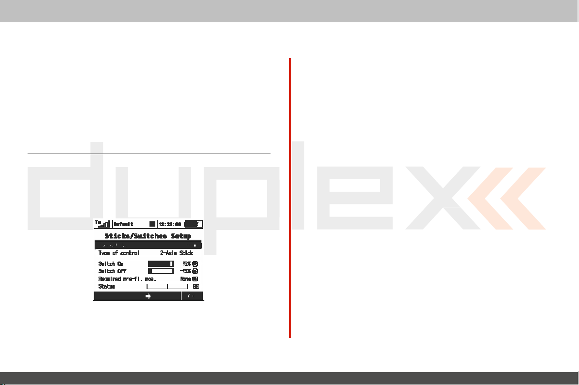
computer
radio
defined (completely
is activated.
5.
This
prevent your engine from shutting-off when you moving
stick to its low position. The
editing the “Idle Offset”
activated,
offset value as a
affected by the idle offset
Throttle Idle S
feature is used to set the idle position for your throttle and will
the minimum throttle setting
9.3.2 Sticks / Switches Setup
This
menu contains System Stick/Switch settings and c
V
arious
functions can be activated by any Switch, Stick or Knob
position. Switch setting enables you to set the points when your
desired
function/timer/telemetry
off
) throttle position once the assigned
etting
minimum throttle setting is defined by
value. When this function has
(idle
point)
percentage. Standard throttle function is
setting.
can be turned ON or
1
3
1. Switch & Stick Type
The first menu line item lists the c
item lists the type of control element. Using the “F2” and “F3”
function
button you can
buttons
you can scr
exit
the menu scr
ontrol’s number and the
oll
through
channels, with the
een.
control
is
defined by
onfiguration.
OFF.
2
4
“F5
swit
ch
throttle
been
the
not
sec
ond
(Ok)”
system
2. Switch
Any
proportional function can be set as a system switch.
item enables you to assign the travel
function ca n be turn ON or
“Switch-ON” –
switch a function ON.
“Switch-OFF” – The point when the control element positon will
switch a function
By
default, the system setting for all
inputs is set to function the same as a 3-position
a) A function above this point is considered to be “Switch
b)
“S
witch ON”
c)
If
the switch setting
OFF”
2-position
3. Required Preflight
For
any functions assigned to the
initial
K
nobs
being
transmitter screen will display the function that is not in pre
programmed, correct preflight
4. Function Status
Position and status of the control is displayed in the status
the right side of this menu you can see status of the switch
ON/OFF P
A
function in this range (middle) can be considered to be
or “Switch OFF”
A
Function below this point is considered to be“Switch
the proportional
switch.
position can be prog
or
Sticks
activated,
oints
percentage
OFF.
The point when the control element positon will
OFF.
proportional channels and for
is
set at same level for “Switch
channel/func
P
osition
rammed.
are not in required preflight position while model is
system will refuse to switch to this
Display
tion output will
Switch, Knob
If
the
position.
at which a
switch.
ON”
or
Stick; any preflight
pre-programed Swit
EN
This
menu
desir
all
ON”
either
OFF”
and “Switch
be the same as a
ches
model. The
bar.
On
func
tion
ed
,
-
4.
4.
Page 60

computer
as an“x”or
check
mark.
1) Setting
If
you have installed the optional stick with a
right
switch
Example
stick, scr
“Sk”
or
oll
thru the Control No.
“Sl”
if
the
button switch is installed in your right
Menu
P
ick
one of the “T
•
“2-Position Switch”
•
“3-Position Switch”
•
“Button”
ype
of Control”
switch
options:
For any functions assigned to the chosen switch, knob or
preflight
initial
position can be prog
rammed.
radio
button
line
and
pick
control
in your left
the
func
stick.
stick; any
system
or
tion
9.3.3 Wireless
Modes/Trainer
The transmitter RF modules can
detailed explanation. (see: section 5) The
programmed
programming
module
mode.
mode, this setting
For safety
switched to
the
transmitter.
to the memory of individual models
a selec ted model you will need to configure the
settings. The
If
the particular model has been
r
easons, the
“Initial”
only exception for the system is the “T
will
not change if the Tx is
“Trainer”
RF
operate in one of three
wireless
programmed
turned ON or
RF
mode
will
mode when a different model is selected
modes. For a
RF
(receivers).
OFF.
be automatically
DS/DC-16
training for
the instructor and
communication between
instructor decides when to give control of the model to the
and when it’s time to step in. The instructor’s
module
communicates
if
only the primary
transmitter.
Other brands of transmitters can be used by the
Duplex
communication
radio systems are excellent tools for
a
student is
communicates
set to “Student”
EX
2.4GHz
not different than
student
the transmitters is done
with model and the secondary
with
student’s transmitter. The
mode, disables its secondary
RF
module to
radio system by using a special wireless “Trainer”
module by Jeti.
instructor
flying his
have their own Jeti
primary transmitter
Student’s transmitter,
RF
communicate
student
pilots. Basic
own
model.
transmitt
wirelessly. The
RF
module and
with
instructor’s
with a
EN
setting is
While
RF
rainer
”
in Trainer
be
in
Both
ers, all
student
RF
module
uses
Jeti
4.
4.
Page 61
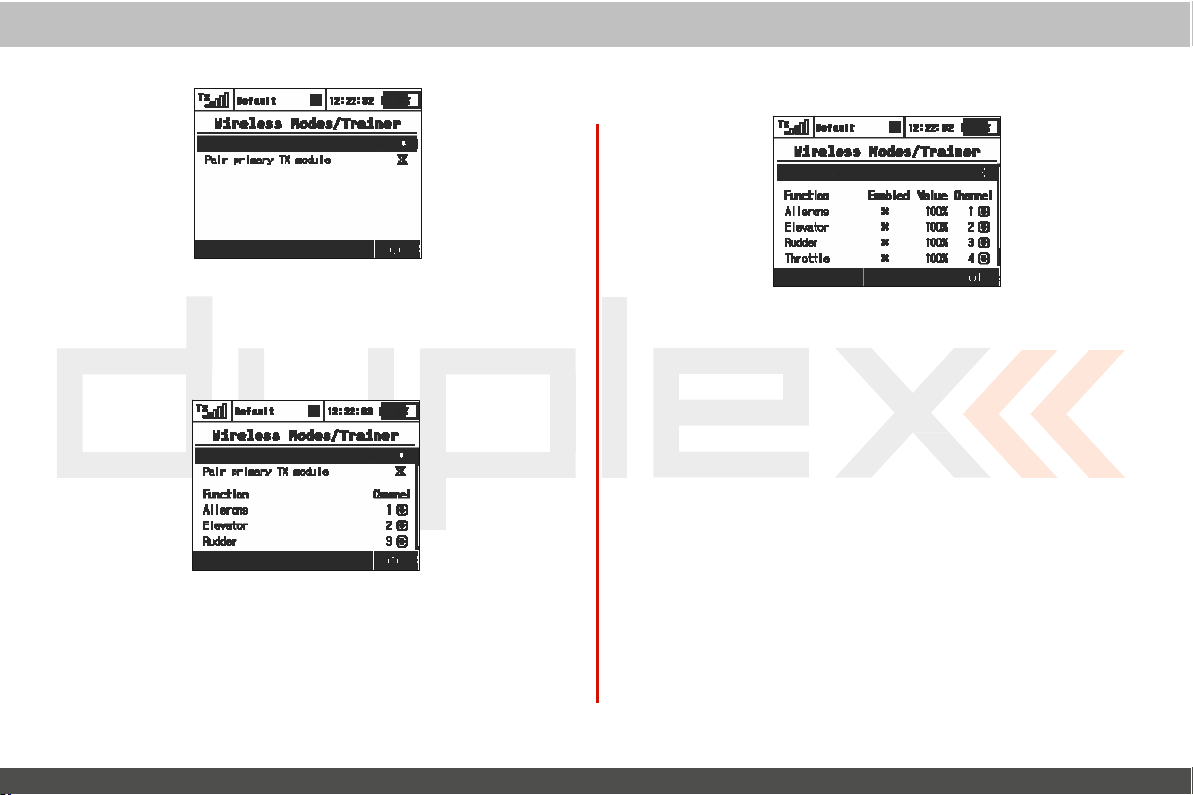
computer
“Default”Wireless
a. Selec
b.
tion
Primary RF module bind control menu
Mode
“Student”Wireless
Mode
If
student’s
or any other advanced features are disabled in the
transmitter.
a) Mode Selec
b) Binding initialization of the
c) Channel function
transmitter if set to
tion.
module or special wireless
assig
nment.
“Student”mode;
I
nstructor transmitter‘s primary RF
“Tr
ainer” module by Jeti.
radio
line
any
dual-rates, mix
control
student’s
system
es
“Instruc
tor” Wireless
Mode
EN
a) Mode Selec
b) Assigned trainer function switch, when the switch
control of the model is transferred to the
c) Binding initialization of the
RF
module with
d) Channel function assignment. Some or
be controlled by
I
nstructor/Student
e)
the amount of control for the student.
assigned a 60% control value to a particular
student
override
f
) Assignment for the input channel from the student’s
transmitter to the Control function of the instructor’s
transmitter.
tion.
I
nstructor transmitter‘s
student’s transmitter.
student.
only assigned a 40%
student’s
control authority
input and correct the
values.
value. The
model’s
is
activated,
student.
sec
ondary
all
of the functions
This
setting limits
If
the instructor is
channel,
instructor can easily
flight.
can
and
4.
4.
Page 62
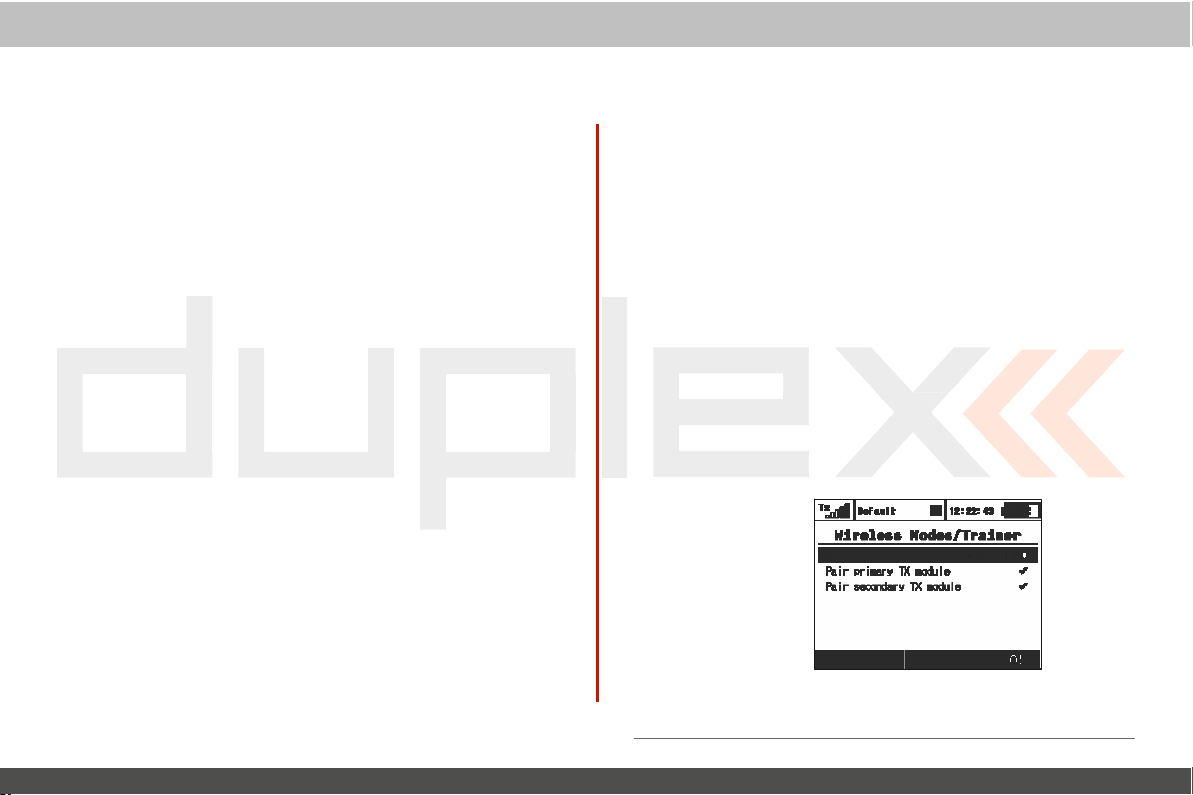
computer
Trainer
Mode with Two
1. Make sure that the
aircraft in the “Default” wireless mode and that all flying
surfaces are functioning
2. Change the
and authorize the secondary
student’s transmitter.
3. Switch
Trainer
Other brands of transmitters can be used by the
Duplex
communication
1. Make sure that the
2. Change the
3. Connect the wireless trainer module to the
4.
ON
to “Student” and allow the
operly.
pr
controlled by the
make the necessary changes in the
aircraft in the “Default” wireless mode and that all flying
surfaces are functioning properly.
and authorize the secondary
student’s transmitter.
Jack”
the instructor
(see the module
V
erify
the
Verify
Mode for Jeti DS/DC-16
EX
2.4GHz
(see
that
all
student’s transmitter. If
Jeti DS/DC-16 R
instructor’s
pr
operly.
instructor’s
the
student’s transmitter,
radio system by using a special wireless “T
module by Jeti.
instructor’s
Tx
manual) then prepare the module for binding to
Tx
of the
transmitter wireless mode to“T
that all of the
student’s transmitter. If
instructor’s
transmitter wireless mode to“T
by inserting the bind plug into the
guide)
air
craft’s surfaces are correctly contro lled by
radio
adios
transmitter is bound to
TX
module to bind with
change its wireless
instructor’s
air
craft’s surfaces are c
student’s transmitter.
as the
Instruc
transmitter is bound to
TX
module to bind with
they are not correct, make
control
transmitter to
they are not c
tor R
adio
student
student Tx “Trainer
eacher
orrectly
orrect,
with a
rainer
eacher
“Ext”
the
the
mode
bind
Jeti
the
the
por
the
system
”
”
”
t
in
the
necessary changes
Trainer
R
1. Make sure that the
4.
Double
Mode for Jeti
adio
is Different – Requires Special Tr
air
craft’s transceiver in the “Def
flying
surfaces are functioning properly.
2. Connect the wireless trainer module to the instructor
“Trainer Jack” (see
binding to the
“Ext”
port (see the module
3. Switch
ON
to “Student” and allow the
pr
operly.
Verify
that all of the
by the
necessary changes in the
Path
student
the
student’s transmitter,
student’s transmitter. If
Wireless
student’s transmitter.
DS/DC-16
Mode
as Student Radio
ainer Module
instructor’s
Tx
manual) then prepare the module for
Tx
air
craft’s surfaces are correctly c
transmitter is bound to
ault” wir eless mode and that all
by inserting the bind plug into
guide)
change its wireless
instructor’s
they are not correct, make
student’s transmitter.
transmitter to
and
EN
Instruc
mode
ontr
a) Mode Selec
b)
Primary RF module bind control menu
c) Secondary
tion.
RF
module bind control menu
line
line
tor
the
T
the
bind
olled
the
x
Page 63

4.
Page 64
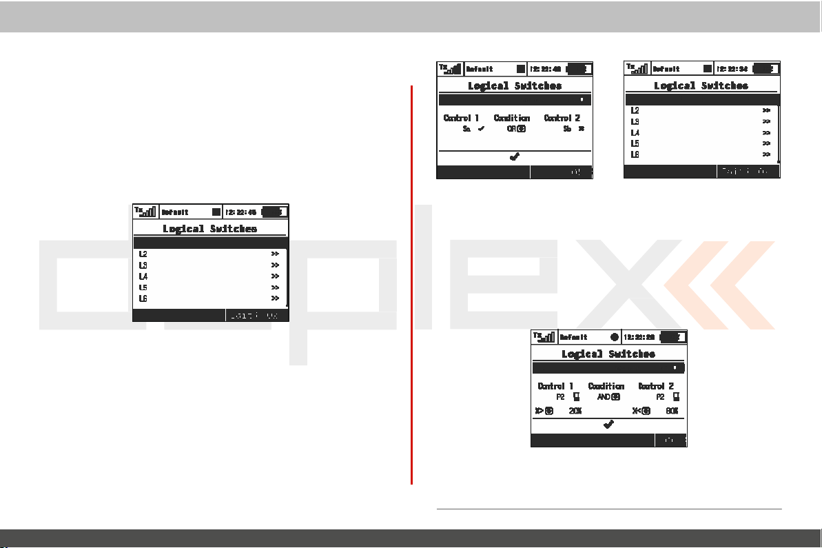
computer
radio
9.3.4
L
ogical S
If you want to have single or multiple transmitter functions which are
controlled based upon the condition of other control c
then setting up a
defined by a logical expression. The
logical function and the relationship of the other conditions
must exist for the logical function to be
that your logical switch can either work like a 2-positon
(
ON/OFF)
or
witches
log
like
a proportional 3-position switch (ON/Center/OFF).
ical
switch is the way to go. Each log
logical expression contains
activated. The end result is
1. Crea
Up to 16
the
switch setup
enabled value to
inputs and conditions on the menu screen. First set the c
inputs #1 and #2 by assigning functions to
After that, select your desired logic
the
displayed by either a check mark or an
current conditon
ting a L
independent
numbered
bottom
of the screen the result of your logical expression is
ogical S
witch
logical switches can be created. Select one of
lines and press the „3D button“ to access the
menu.
To
enable the switch highlight and change
“Yes”
.
Once activated you can see the c
swit
ches, sticks or knobs
state.
statement
(OR, YES,
„X“, depending
control
onditions
ical
switch is
Multi).
upon
which
swit
log
the
ontr
ontr
On
the
system
a
ch
ic
ol
ol
.
EN
2. Logical
Logical
proportional
„F2(Prop)“
allow the use of proportional controls an additional condition
will
appear. In
value of the channel as well as by the value from which the
will
be in
to calculate the
Example: This
example,
ON
position.
switch
Switch Proportion Calcula
rules can also be created when your logical switch
channels.
button
this menu the conditions can be set by
its full ON/OFF
figure shows the use of proportional processing by a
if
the P2
stick is
If
the
the
OFF
P2 stick is
position.
is in
To
enable proportional evaluation press
when you select your input c
position. Those
log
ical r
esult.
moved between
moved from
All 16 logical
20%
0%
switches can be c
and
80% of its travel
to
20% or
tion
ontr
conditions
the
from
80%
to
onfigured this way if
ols. When you
percentage
will
then be
logical
switch. In this
logical
switch is in
100%
then the logical
needed.
uses
the
menu
swit
used
ch
the
4.
4.
Page 65
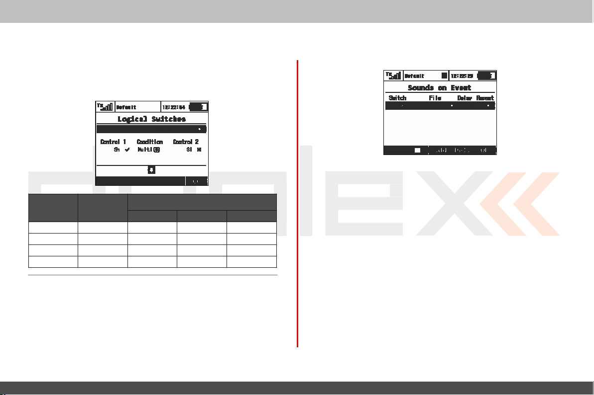
3. Emulating a 3-Position Switch
You can use the logic function
as a 3-position switch. The “Multi”
output
from two 2-position switches to create a logic switch
three
output conditions.
computer
“Multi”
radio
to allow the logic switch to act
logic function can combine
Switch 1 Switch 2
The result of the
ND
A
9.3.5 Sounds on Ev
You can assign an audio file to be played based on any
condition.
can be assigned to any switch,
any other special function. Since you can also upload music
the DC/DS-16, you can fully customize how your
communicates
This
ent
(Sound
means than any music
with you.
If
multiple sound files are triggered at
Assignments)
file
stick, knob, logical switch, alarm
control
operator
OR
M
stored in the
with
ulti
transmitt
transmitt
files
transmitt
the
system
the
er
er
or
the
er
same time they will play at the same time and their sounds will
overlay each
1. Sound Switch
Select the
to use to trigger the sound
2. Selec t the Sound File
Select the
assigned to the switch. The
Directory/A
own
3. Sound Playback
The playback of any
editing
4. Sound
This
been
time is
other.
Assignment
“Switch”
“File”
udio.
files.
the
“Delay”
menu item allows you to repeatedly play any sound after it
activated. This
short.
menu item and assign the switch that you
pla
yback.
menu item and select the sound file that you
available audio files are stored
This
is
menu it
Repeat
important
Delay
sound, after activation, can be delayed by
em.
can be useful
to
remember
if
your selected
if you upload your
EN
sound’s pla
want
want
has
ying
in
4.
4.
Page 66
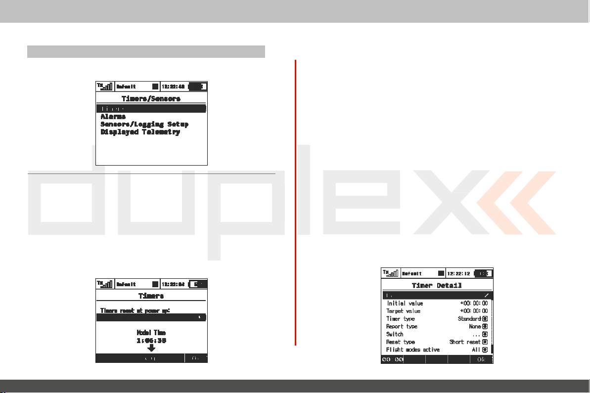
9.4. T
-
Set up of Timers
9.4.1
The
timers.
lap
want. You
it
are stored in each
of
computer
imers/S
T
imers
DC/DS-16
This
times, total flight time or just about anything else you c
is
displayed in its own box on the desktop screen. The
all
of the timers you have created.
ensors
and T elemetry Sensors
allows you to simultaneously use up to 10
is useful to separately track motor run
can also name each of the
model’s setup. The „Timers“
radio
timers. Once you create a
control
times,
timer
menu displays a list
different
individual
ould
timer
values
system
1. Model Time/Reset T
By
pressing F1()
after turning on the
timers with specified Shor t Reset option are
possible to have all timers cleared or
specific. The
pressing
Button
It is possible to show the model time on the main scr
„
2.
From the
„F2(Add)“
3. Deleting
Use the
4.
Use either the
„ Timer Detail“
the timer
F(4)
F(3)
Timers/Sensors->Displayed Telemetry”.
Creating a
„F3(Del
Editing T
button
model time runs incrementally during flight
Start
clears the model
new Timer
„Main Menu
button to create a new
a T
.)“ button to delete the selected
imer S
„F3(Edit)“
menu. Then
settings.
imers
at Power Up
you can choose which timers
TX
or after selecting the
button on main screen or after starting any t imer).
time.
> Timers/Sensors >
timer.
imer
ettings
button
or the „3D button“ to enter
use the
„3D
model.
cleared. In addition, it is
none.
This
Timers“
timer.
button“ to select and
EN
will
be reset
By
default, all
option is
menu, press
model
(after
een
the
the
edit
Page 67

computer
radio
control
system
EN
4.
4.
Page 68

computer
radio
1.
Editing a
a). Timer Name
When you add
displayed in that
Initial T
b).
This is
a negative or positve value for
c). Target T
is where you can set the target value for the
Here
set as a positive value or a negative
value will
smaller than the
value is larger than the
d). Timer type
T
here are three possible timer types:
•
Standard – The
is
triggered and the timer pauses when the switch
timer’s
„F4(Stop)“
•
Laps - The
Once the timer is
elapsed time is stored in memory and the timer resets to your
initial
displayed each time the switch is
button
through the stored lap
•
Free-Running – The
New Timer
or change the timer
timer’s
box on the main
imer V
alue
where you can set the starting value for the
imer V
alue
determine
value is not reset when the timer is
button to stop the
value. The
to stop t he
the
initial
value the timer
initial
timer starts or resumes when the chosen
timer starts when the chosen switch is
started, each time the switch is
l ap number changes and the c urrent lap time is
timer. Then,
times.
timer starts counting when the
name, the name
this starting
value. The initial
timer‘s
direction.
will
value the timer
timer.
triggered.
you can use the
desktop.
point.
count down.
will
control
is
aut
omatically
timer. You
timer.
If
the ta rget value is
count up.
is
paused. Use
Use the „F4(Stop)“
„3D
can
set
This
can
value and
turned
triggered, the
button“ to scroll
tar
If
the
tar
swit
off. The
triggered.
chosen
chosen
get
get
the
system
be
ch
switch is
st
opped
Use the
e). Report
You can use this item to select the type of audio alarm for the
Some of the choices will create an audible warning which
just before the target value is reached.
f
). Switch
T
his
See chapter
g). Reset
The
If
you select „Short reset“ the timer is reset by a shor t press of
„F5(
If
you select „Long reset“ the timer is reset by a long press of
„F5(
h). Flight modes
This
timer is active.
triggered.
using the„F4(Stop)“
„F5(
item is used to assign the switch or
type
„F5(
Clr)“ button is used to reset the
Clr)“ butt
Clr)“ butt
item allows you to select which flight mode(s) for which
Once
started, this type of timer can only
butt
on.
Clr)“ button from the desktop to reset the
type
button to start the
9.7:
„Select input control“.
on.
on.
ac
tive
timers.
EN
be
timers.
timer
sounds
timer.
the
the
the
While you are in the „ Timer Detail“ menu the timer initial value is
displayed in the
first
function
key
position (bottom, left).
.
Page 69

computer
radio
control
system
EN
4.
4.
Page 70
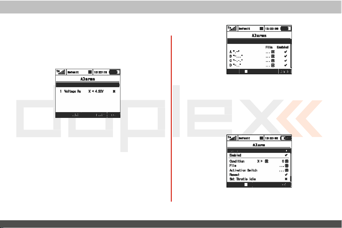
computer
radio
9.4.2 Alarms
If
you use the Jeti telemetry system, in this menu you can set your
alarm thresholds and choose which sound is played in the
condition. The
Duplex EX
transmitter support both
alarms.
first generation
F
irst Generation Alarms
First
generation
Morse Code.
you must select „Enable Morse Code Alarms“ using the „3D
button“. When this option
the first column shows the Morse Code alphabet. The sec
column shows the .wav sound
the „3D Button“ to change the .wav
third column shows whether the selected .wav
enabled.
as
needed.
saved for
Duplex
(non-EX)
If
you are using first
Use
the
„3D
button“ to enable or disable the alarm
This
configuration must be set for each model and is
each model
independantly.
sensors
generation
is
selected, a table
files
associated with each
file
generate
Duplex sensors
appears. In
association as
file
control
alarm
Duplex
their alarms
needed. The
for each letter is
this
letter.
and
as
then
table
ond
Use
sound
system
,
EX
Alarms
Duplex
EX
sensors
generate their alarms directly to the
The
corresponding
Duplex
transmitter. It may take several minutes for
communicate
„Main Men
For
must be c
EX
u >Timers/Sensors >Sensors/Logging Setup“.
this operation, both the transmitter and
onnected
Duplex
EX
sensor must first be
receiver and the receiver must be bound to
the
sensors. The list
and powered.
of
connected
1. Crea
Use the
item, select the sensor whose alarm
ting
an Alarm
„F2(Add)“
button
to add an alarm. Then,
limit
EN
transmitter.
connected
the transmitter to initially
sensors
is
found in:
all
receivers and
in the „Sensor“
you want to
set.
sensors
to a
the
Page 71

4.
4.
Page 72
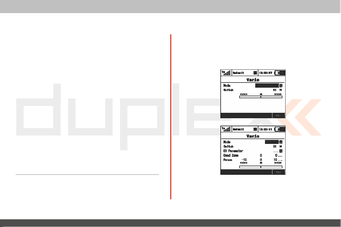
computer
radio
2. Enable an Alarm
Us
ing the „3D
alarm and display the alarm
3. Parameter Values
„Condition“ defines the condition which must be met in order
trigger the alarm. The
4. File
This
item allows you to select the audio
alarm occurs. Press
stop playing the selected audio
Repeat
5.
If
the alarm condition occurrence is longer than the selected
file,
you can use this item to repeat the audio
displayed then the audio
the audio
6. Set
With
this item
alarm condition occurrs.
7. Activation Switch
If
the switch is
to the switch
button“, select „Enabled“ and press to enable
„F1“
file will
play
Throttle Idle
activated,
assig
status.
paramet
value „X“ will vary with the sensor being
to play the selec ted audio
file will
only once.
you
ned, the alarm is enabled or disabled according
file.
repeat.
model’s
ers.
file
throttle
that is played when
file. If
If
an
„x“
will
go to idle when
control
used.
file.
Press
„F2“ t
audio
a check mark is
is displayed
the
t
the
then
the
o
o
system
9.4.3 Vario
L
ocated in:
acoustic
alarm.
model. It
sound. The
rate.
The second mode of the Vario
acoustic signalling varies directly
numerical values sent by the
switch that enables the acoustic
„Men
u->T
imers/S
ensors/Vario”. T
sig
nalling. The first
This is
mainly useful
is possible to assign a switch that enables or disables
slider at the
one
if a non-EX
bottom
is
controlled directly by the
shows the actual value of
is
sensor. It
sig
nal.
EN
here are t wo types of
MVARIO is
dedicated
depending
is also possible to assign
installed inside
climb/sink
to
EX
sensors. The
on the actual
sensor's
the
the
a
4.
4.
Page 73
computer
radio
Other
parameters
•
EX Parameter.
parameter
R
ate
is predefined by default
are free to choose one of the other sensors and their
example: an RPM
•
Dead Zone (negative and positive).
around the centre of the range with no acoustic
relative to the c
•
R
ange
the full range of the sensor which will be indicated by the Vario
system.
displayed in this menu are:
Here you can selec t your sensor and
which
will
act as a source for the Vario
(if
the
probe to indicate high rev
enter.
(minimum, center and maximum). Here you can
MVARIO EX
is
olutions).
This
system. The
detected)
field sets an area
sig
The actual value of the sensor and its
indicated at the
Negative dead
Minimum Maximum
P
bottom of the scr
ermanent sound
zone
C
entre of range
Silence Beeping...
appropriate Vario output are
een.
Posi tive de ad
control
Climb
but you
parameters
nal. Values ar
define
zone
system
its
(for
e
9.4.4 Voice
This
powerful function makes it easier for
know their actual telemetry values often but they don't want to (or
cannot) look at the display because it may be
danger
ous.
Output
all
modellers who need to
EN
inconvenient or
Voice output for a timer
The
first
menu row represents
The actual status of a single timer can be expressed by a
v
oice. If
you select the desired timer and a switch, every time
switch is
If
with checkbox appears
allows you to
current lap which
lap which has ended rec
Voice output for telemetry
T
values. The first
of seconds elapsed is displayed over the
assign a switch to enable or disable the
Every
reported
timeout is reached.
The second voice queue specifies which variables are
once,
and a
activated,
the timer type equals
determine
here are t wo
time this switch is
after a single press of a switch. You
list
independent
queue repeats its message every x seconds
by voice and then the c
of variables that are reported
settings for
the actual time is stated
“Laps” type, another menu row
below. In this row,
whether you want to hear the time of
is
already
running, or hear the time of the previous
ently.
queues
activated,
ountdown starts a new round until
the voice
dedicated
F(1)
repeating
the
can select a Trigger swit
when the switch is
output
synthesiz
aloud.
“Report previous
to
output telemetr
button). You
of the c
appropriate
variables are
reported only
activated.
of a
timer
equipped
(number
can
also
ountdo
ed
the
lap
y
wn.
a
ch
.
”
a
4.
4.
Page 74
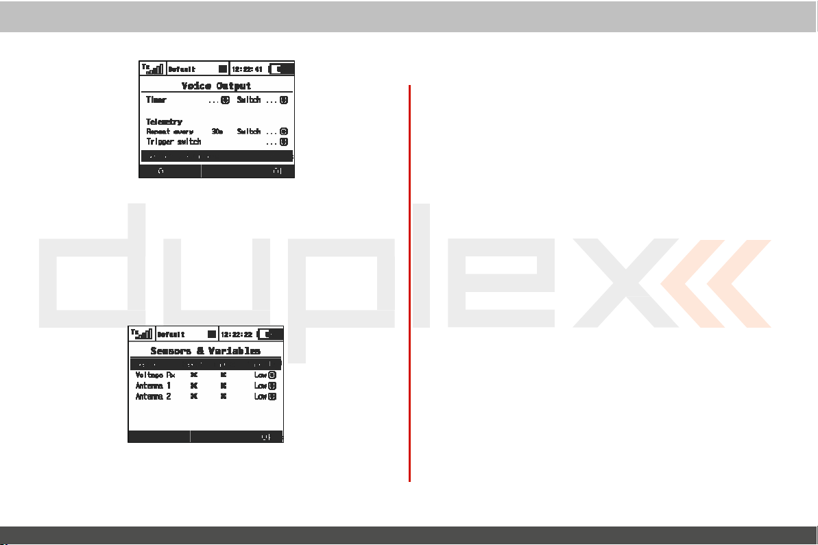
computer
radio
By
selecting the pushing the “Sensors
3D rotary button, you are able to choose which variables will
expressed by a sy nthesized voice. The first column
name of the sensor or
way to add a variable to the Repeat queue or to remove a
from the Repeat
variable is added into the Trigger queue, so that every time
T
rigger
switch is
expressed by synthesized voice.
variable. The
queue. By selecting the Trigger
activated,
the items in the Trigger
& V
ariables” option using
Repeat option provides an
option, the
You may change the
order of the
Medium and
Low priority.
priority of any
reported items. Possible choices for priority are: Low,
High. The or
der, top to bottom,
variable. This will
is
from High priority to
control
represents
variable
specified
queue are
also change
the
be
the
easy
the
the
system
EN
4.
4.
Page 75
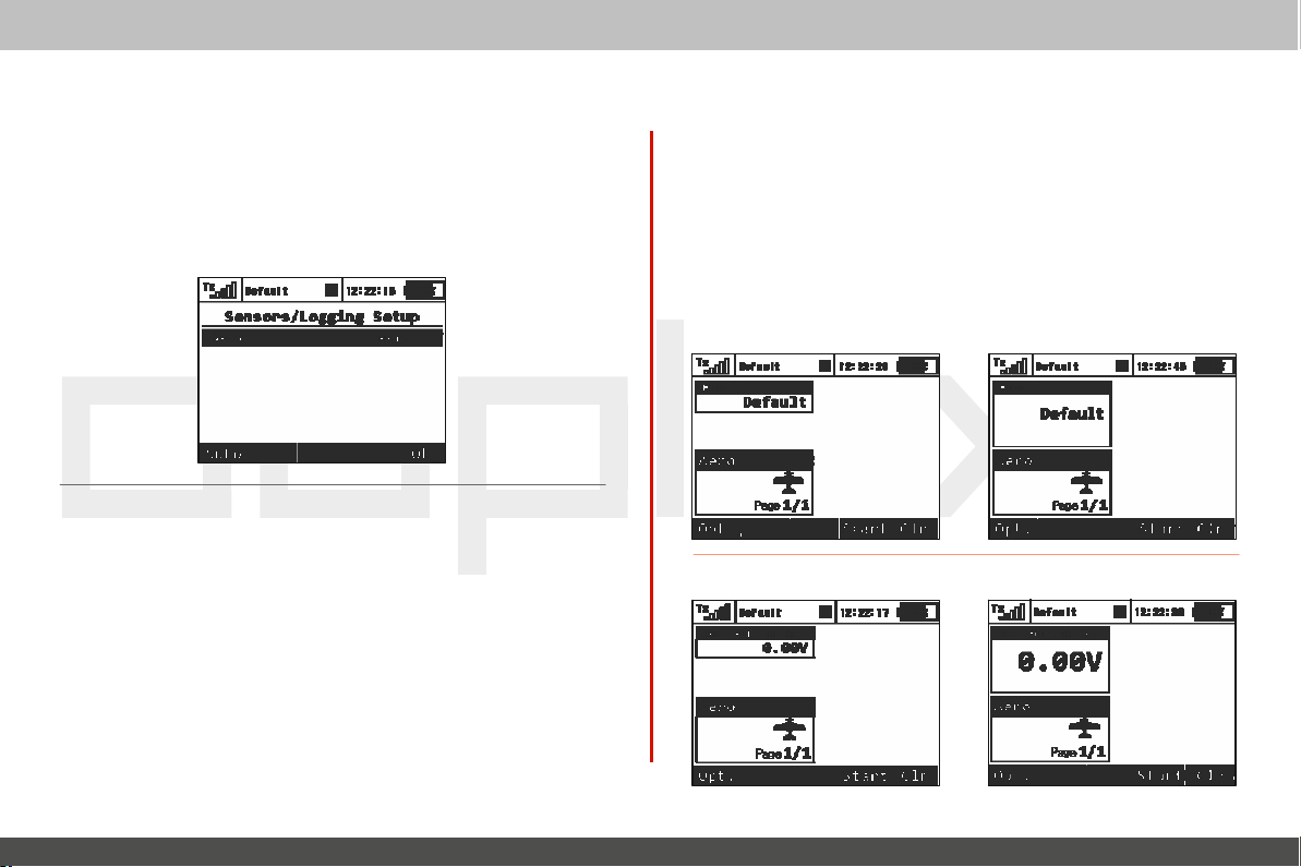
computer
9.4.5
S
ensors/L
This
menu lists all of the Duplex
are
operating in
EX
receiver it may take several minutes for the sensor to
recognized by the transmitter and added to the list.
In this menu you can edit the telemetry
ogging S
your
model. When you connect a sensor to a
etup
radio
control
EX
sensors and their values
parameters of
each
which
Duplex
sensor.
system
be
EN
9.4.6 Displayed Telemetry
This
menu
lists all
of the user information blocks which are
on the
desktop.
rename and resize the user information blocks displayed on
desktop.
You
can use this menu to manually
displayed
add,
delete,
User Block Overview:
"F
light
mode" - Name of the
„Voltage
Rx“ - Receiver Voltage
current
flight
mode
the
Page 76

computer
radio
control
system
EN
4.
4.
Page 77
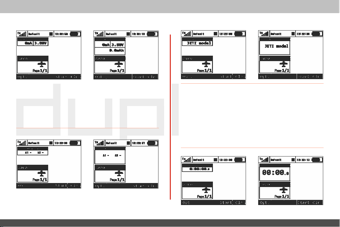
computer
radio
control
system
EN
„User
„Tx
Battery“ - T
ransmitter
Battery
Status
•
Charge/Discharge current
•
Actual Tx battery voltage
•
Consumed capacity of
transmitter is in use and decreases when the battery is
Tx
battery
rate
This
value increases when
the
charging.
Name“ - User
„Jetibox“ -
JETIBOX
name.
emulation scr
een
"Antenna" - Inf
ormation
about the signal
strength
of each
antenna
„Timer“ - T
imer
Page 78

computer
radio
control
system
EN
4.
4.
Page 79
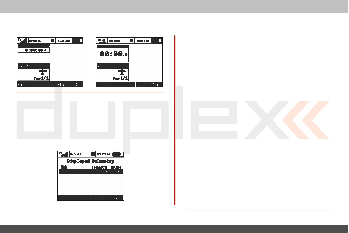
computer
radio
„Telemetry“ -
Displays
inf
ormation.
selected,
connected
telemetry
The user blocks can be either standard or double
blocks obviously use up more of the
them isplay more data while others display the same data in
larger font.
Custom blocks can be linked to flight
can set up different groups of blocks for each flight mode creating
completely different desktop
another.
appearance
desktop.
modes.
In
This
from one flight mode to
control
sensor
size.
Double
siz
return, some of
means that you
system
ed
a
a
1.
Creating a
In the “Displayed Telemetry”
add a blank user block to the list.
first item of the new
cr
eate. Next, in the second line item, select whether you want
new block to be double
2. Change the
Using the „3D button“ highlight your selected user block in the list.
Use the
down the list.
3. Deleting a User
Use the
list.
4. How
The right end of the first line in the „Displayed Telemetry“
displays a symbol to indicate
all flight modes or just the current flight
symbal)“ is displayed then the all of the listed user blocks are
displayed in all of the flight
change flight
(Separate symbol)“ symbol
blocks are only displayed in the current flight
when you change your flight
change. When using
each flight
highlighting the
new user
U
„F1“
and
„F4(Del)“
the User
modes, your desktop display
mode. You
first line
block
block’s
line to the ty pe of block you want to
size (yes)
ser
Block order
„F2“
buttons
Block
button
to delete the selected user block from
Blocks are
is
separates
can change from Global to Separate by
and pressing the
menu, press the
Using
or not (no).
to move your selected block up
Displayed
if
the list of user blocks
modes.
displayed then the current
modes, the desktop display will
you must create a user block list for
“F3(Add)”
the
“3D
button” change
mode.
This
means that when you
will
not
mode.
„3D button“.
is
displayed for
If
the
„G (Global
change.
list
This
means
EN
button to
the
the
or
the
menu
If
the „S
of
user
that
also
Page 80

computer
radio
control
system
EN
4.
4.
Page 81
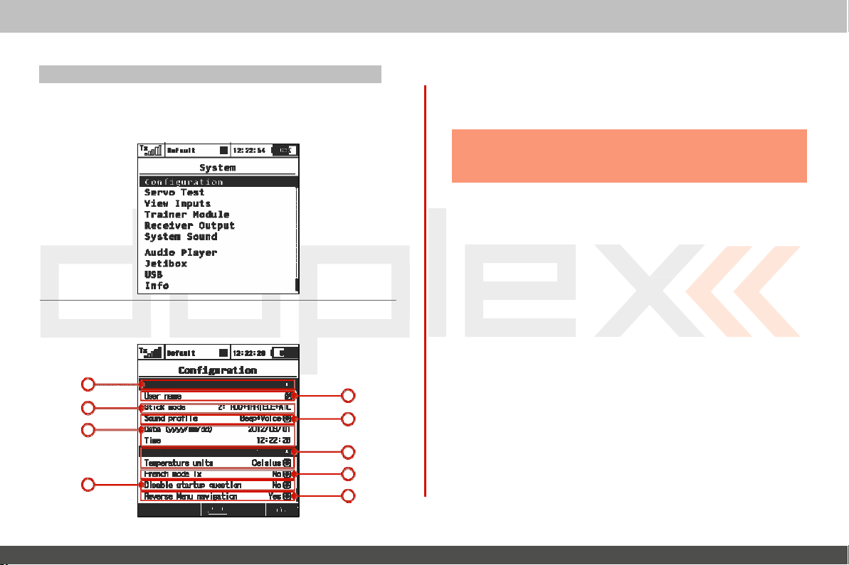
9.5. System
- Use this menu to configure the system functions of your
transmitter.
change when you switch
All
computer
radio
of the settings in this menu are global and do
between models.
C
9.5.1
Basic
onfigura
transmitter
tion
settings
1
3
5
8
control
2
4
6
7
10
system
not
1. Language Setting
Use this menu to select the
All
of the
transmitter’s text and sounds will changed based
your
selec
tion.
Warning: After changing the
turn the
take
2. User Name
Enter the user name that you want to appear in the User
desktop.
3. Stick
The transmitter supports Modes 1-4.
can either use the „3D button“ to highlight and select the line item
or simply press the
menu. Use the
Mode
then press the
only be effective
their existing
4. Sound
This
item allows you to select the sound profile for your
This
determines
with you. You
voice (sound
5. Date and
Here is wher e you set the current date and
automatically observe the time change for Daylight Saving Time.
The time and date information is used when creating new
and for t
effect.
Mode
„F5(Ok)“
stick modes.
Profile
can select between; quiet (mute), beep
file)
T
elemetry.
transmitter’s language
transmitter’s
transmitter
„F3“
„F1-F4“
for new
how your transmitter will audibly c
or voice (sound
ime
off and back on for the change
To
change the stick mode you
button. Either
buttons
button
models.
file) only.
to make your selection
to confirm. The
All
of your stored models
setting.
language you need
will
take you into the Stick
mode change will
time. The DC/DS-16
EN
block on
will r
transmitter.
ommunicat
only,
beep
models
upon
to
to
the
and
etain
e
and
will
Page 82

computer
radio
control
system
EN
4.
4.
Page 83
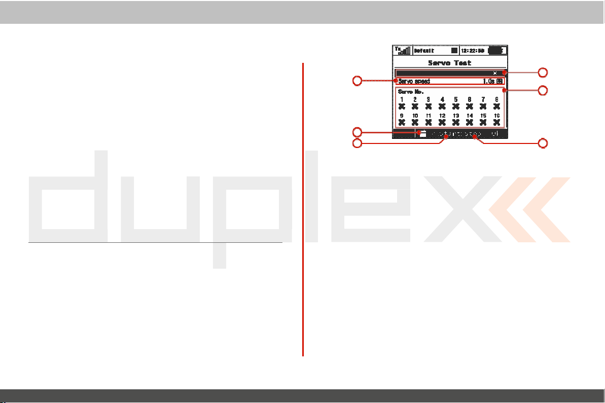
computer
radio
6. Distance
This
menu item allows you to select the distance units for your
telemetry
your selected units for display.
7. Tempera
T
his
menu item allow you to select whether your
displayed
8. Fr
Activate this menu item if your
9. Disable Star tup
This
menu item disables the
(see Chapter 6)
10. Reverse
This
menu item allows you to reverse the direction that the „3D
control“
units
display. All
ture
units
in
Farenheit or Celcius.
ench Tx
Mode
Menu na
scrolls
through the
telemetry data is automatically converted to
DC/DS-16 is
Question
viga
question/confirmation
tion
menus.
being used in France.
9.5.2 Servo & Range T
T
his
menu allows you to perform a range test and servo tests.
During the servo test it is possible to send the test
channels which are active in the current model
speed item allows you to adjust the travel time for the servos
the servo test. During the test, the servos
programmed
included in the test.
maximum
est
will
throws. You can select which servos
control
temperature
during
star
output
to
all
setup. The servo
only be driven to
data is
tup
of
the
during
their
will
be
system
.
1
5
3
EN
6
2
4
1. Servo
This
servo test.
The time shown is the time that it
one travel extreme to the
Note:
2. Servo
Use the “3D Control”
mark) or not included (X) in
3. Starting the Servo
Press the
outputs.
Once
menu.
You must stop the servo test before you can change any of the test
settings
speed
menu item allows you to adjust the servo travel speed for
will
take for
the servo to move from
other.
A
servo
will
only move to it’s
Number
“F3
started, the servo test
(speed,
to select which servos
T
(Start)” button
output channel).
est
programmed
the servo test.
to start the test for your selec ted
will
continue to run even
maximum
will
be included
if
throw.
(check
servo
you exit
the
the
4.
4.
Page 84
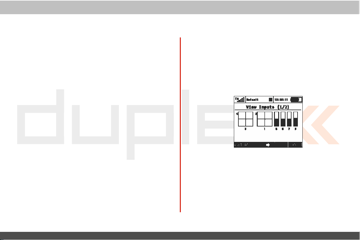
computer
radio
4. Stopping the Servo Test
„F4
„F2
(Stop)“
(Servo
Press the
5. Display Receiver
Press the
to your selected receiver
6. Range T
This
menu line allows you to set the transmitter
test
mode.
See the receiver instructions for how to set the receiver to its
test
mode.
button to stop the servo test.
Monitor)“ button to see the
est
Outputs
channel.
outputs
output
control
being
to its
sent
range
range
system
9.5.3 View
This
menu allows you to view input from the transmitter
switches and knobs as
menu also contains a wizard to guide you through calibrating your
transmitters proportional c
It is
recommended
•
You change from modes 1-2 to modes 3-4
•
The proportional controllers do not move to the extremes of
graphic
Inputs
display
detected
to calibrate your proportional controls
by the transmitter
ontr
ols.
EN
sticks
software. T
when:
his
the
1. Calibration
Press the
perform the calibration. Press the „F5
Follow
slowly to their maximums a few times and return them to
centered
calibration. You will
„F1 (Calib)“
the onscreen directions:
of Proportional Controls
button. You will
Move
positions. Press the „F1
be taken back to the „View
be asked
all
of the proportional c
(Calib)“
if
you
(Yes)“
button
button
Inputs (1/2)“ scr
really
want to
to confirm.
ontr
ols
their
again to finish
een.
,
4.
4.
Page 85
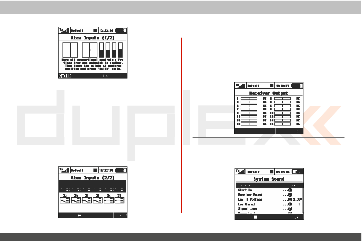
computer
radio
2. Proportional
The „Display Inputs (1/2)“ screen displays the currently
position of each proportional c
Input Display
ontrol.
3. Switch Status
Press the
This
transmitter’s
the displayed
reserved for the switches that can be
transmitter
„F3“ button to show the „View
screen shows the type and currently
sticks.
Display
swit
ches. Use the
swit
ches. The
Inputs (2/2)“ scr
„3D
control“ to select an edit any of
„Sk“ and „Sl“ switch positions are
mounted
control
een.
detected
position of
into the ends of your
detect
system
ed
the
9.5.4 Receiver Output (Servo Monitor)
T
his
menu displays the receiver
the
transmitter.
programmed
output
as a
„Pin-Out
output
channel numbers may not be accurate.
Duplex receiver
be accurate.
You
can press the „F3“
receiver
percentage.
Setting“ of your Duplex receiver then the displayed rec
still
has its default channel settings then this
output
channels being
output
function names and their
If
you have modified the „Channel Set“ or
9.5.5 System Sound
T
his
menu allows you to assign any available sound
ev
ents.
generated by
button
to see your
If, however, your
file
to the syst
EN
curr
ent
eiv
list
will
em
er
Page 86

4.
4.
Page 87
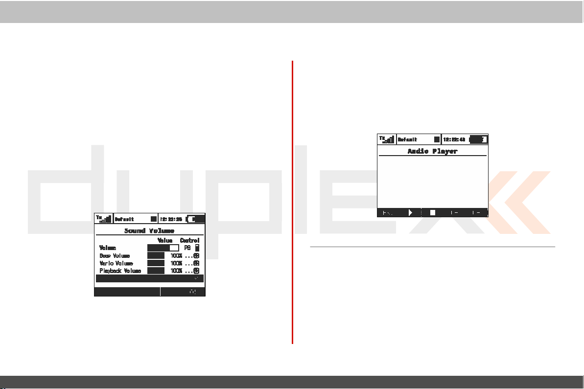
computer
radio
9.5.6. Sound
Here you may select volumes for each part of the audio syst
individually. You
(stick or knob) for
volume for the
to this
value.
•
Beep V
•
V
ario V
•
Playback Volume
Player
and Sound on Ev
•
Stop Playback Swit ch – after activating the assigned switch (in
the picture
doesn’t
V
olume
are also free to assign any proportional c
adjustment. The
transmitter.
olume
– controls volume of
olume
– intensity of vario tone
– volume of played
ent).
Sj), all
currently played
influence any further
first row
Other volumes are then derived relativ
beeping
sig
nalising.
WAV
pla
WAV files
yback.
are being stopped. This
control
ontr
represents a mast
and
trimming.
files
(Alarms,
Audio
system
em
ol
er
e
9.5.7 Audio
This
menu lists all of the data stored on your
memory.
The available audio
control“ to access and scr
function keys provide playback control: „F1
(Stop)“,„F4 (Vol -)“
Player
files
are stored in the Audio folder. Use the „3D
oll
and
through the
„F5
(V ol+)“.
Audio
A
udio files
are
supported in *.wav format.
transmitter’s
folder c
(Esc)“,
„F2
EN
ont
ents. The
(Play)“,
internal
„F3
4.
4.
Page 88
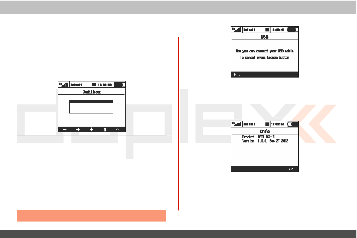
computer
radio
9.5.8
JETIBOX
For maximum compatibi lity with 1st
DC/DS-16 is
emulation shows its information in the legacy two-line
format.
to view or change the individual
wirelessly access a bound rec
telemetry sensors c
Use
generation
equipped
the function keys to navigate the Jetibox menu in order
with a Jetibox emulation function. This
paramet
eiver’s menu and/or any c
onnected
to the rec
eiver.
9.5.9 USB
This
menu allows you to establish
DC/DS-16
cable.
and a PC once you have
How to connect your
M
anually
1.
2. When propted, connect your transmitter and the
cable.
Note: Leaving
DC/DS-16
enter the menu:
the menu disables the connec
communication between your
connected
to a PC:
„Menu,
>System, >USB“
control
Jeti
DUPLEX,
displa
ers. You
can use
onnected
the two with a USB
PC
with a USB
tion.
system
the
y
also
9.5.10
This
product
„F5 (
Info
menu displays information about your DC/DS-16 such as:
name, firmware version, available
Ok)“ button to
exit
this
menu.
memory, etc.
EN
Press
the
4.
4.
Page 89
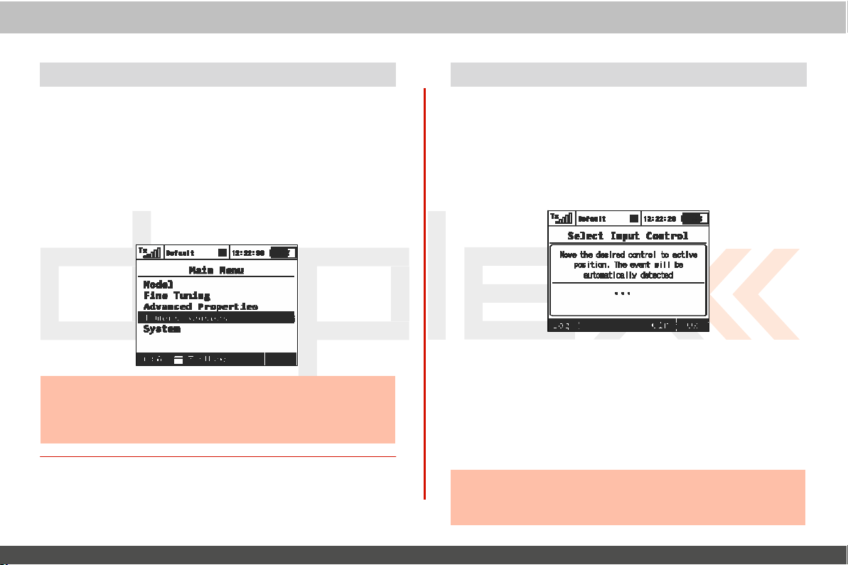
computer
radio
Throttle L
9.6
Throttle
lock is an
DC/DS-16
the throttle channel
can not accidentally star t your
the throttle lock go to the „Main Menu“ and then press the „F1
(lock/unlock)“ button.
to indicate the lock/unlocked condition.
throttle is locked you
the top bar of the
transmitter. T
ock
important
output
will
desktop.
safety feature
his
feature
You
see a padlock icon appear in the center of
effectively
in the closed or off position so that you
model’s motor. To
will
see the small padlock icon
incorportated
disengages
activat
Additionally,
Hint:
Use the throttle lock whenever you are handling a
whose power system is ac tive to eliminate the chance
accidentally
starting the
activating
motor.
the throttle and unexpectedl
control
in your
or „locks“
e/deac
change
when
model
tivat
the
system
e
of
y
9.7 Select Input control
This
menu allows you to select your desired input control
(switch, knob,
will
appear any time you edit an input control device seletion. In this
menu you can also assign/edit how a control device
can set the contol device to have two types of proportional
or just a simple ON/OFF function. From this menu you can
reverse the control
1. Switch
When the menu
to
select/edit
move the
function. When you move the chosen control device it will
recogized and assigned to your function. The
and current status is
use the function
Hint:
Think abo ut what
control to work and move the stick, switch or knob
position before you enter the
stick
or logical switch) for a given function.
device’s functional
Assignment
appears, you can either press the
a logical switch for your function or you can simply
stick,
switch or knob that you want to use to control
displayed. Once the control is activated you
butt
ons
direction.
to configure the control
position/direction
assignment menu.
control device
device.
that you want
EN
This
func
tions. You
„F1 (Log)“
devic
menu
output
butt
name
into
e
also
on
the
be
can
the
4.
4.
Page 90
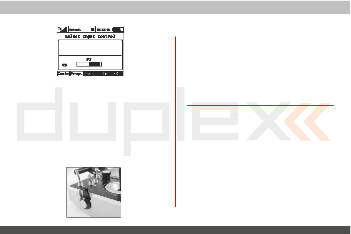
2. Proportional Settings
Press the „F2 (Prop)“
have either proportional or
setting
will
not be available for all
For
example, you have selected a 3-positon switch for
If you
select:
•
Non-proportional – The
•
Proportional – The
3. Reversing
Press the
direction.
„F3 (Rev)“
computer
button
to make the selected device c
non-proportional
control
brake can have
brake can have up to three
button
to change the control device
radio
control input. This
devices.
only
two
control
your
positions
positions
activation
ontr
airbrakes
system
ol
.
This
will not reverse the
simply reverse the direction of the control
swit
ch,k
nob)
4. Removing the Switch
Press the „F4
device from your function.
device if you wish or press the „F5
func
tion’s
Once you are happy with your control device seletion
configuration, press the „F5
confirm.
(Clr)“
menu without assigning any control
output
direction of your function. It
Assignment
button
to clear (remove) the selected c
You can then select another c
(Ok)“
button
(Ok)“
button
or the „3D control“ to
device.
EN
device. (stick
to return to your
will
ontr
ontr
,
ol
ol
and
4.
4.
Page 91
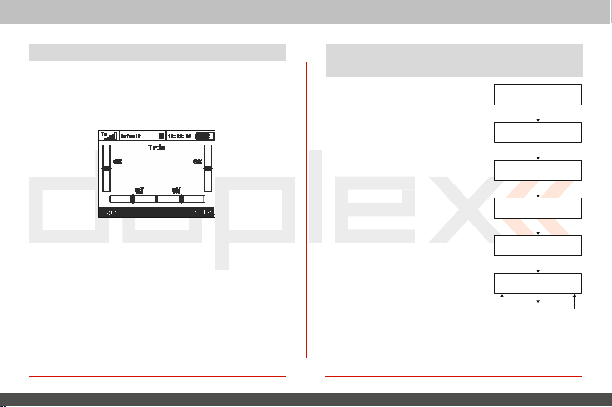
computer
radio
9.8
Trim
Menu
This
menu displays the cu rrent trim
menu from the desktop by either pushing the „3D control“ or by
simply pushing one of the trim
the „F1 (Back)“
activate the Automatic Trim feature.
When the Automatic
based upon your flight stick
defection, the faster the trim value is set in that direction.
the auto-trim process you
settings. You
butt
ons. In
button
to exit or push the „F5 (Auto)“
Trim
is
activated,
still
have normal control of your
the trim is automatically
positions. The
this
menu, you can press
farther the stick
control
can access
button to
During
model.
this
set
system
9.9 How Tr
are Processed
This
chart displays how the
output
what point the various configuratio
choices affect the
When you move a control device (t
block), the
according to its
curve „Menu, >Fine Tuning, >Function
C
u r v e s “. A t t h e s a m e t i m e a n y
programmed
F o l l o w i
exponential is applied and then any
rate limits are also
applies any mixes and/or prog
flight modes to the
any servo setup configuration items
point, subtrim, reversing, etc.) are
implemented
mode trims are applied to the
output function.
ansmitter Output Func
transmitt
functions are processed and
output function.
output
n g t h i s
function will mov
programmed
delay is also applied
, a n y p r o g r a m m e
applied. The
output
and then any trims or
func
dual
next step
rammed
function. Now
(end
flight
channel’s
er
at
n
op
e
tion
d
tions
Control
Flight Function Curves
.
,
T
Dual Rate
rims
–
Dual Rate
Mixes
Servo Setup
Channels
EN
Devic
e
Exponential
– Throw
F
light
Mode
T
rims
4.
4.
Page 92
computer
radio
10 Tr
ansmitter to
The Jeti Duplex line of transmitter s
The Transmitt
which is used to connect your transmitter to a
system is fully compatible with M icrosoft Windows
versions of Windows OS. After
transmitter will be identified by the PC as another memory
While
charged
it is
connected
via
ers
also come with a standard
the
USB port.
PC Connec
to a
PC
tion
is
equipped
connection
your
transmitter‘s battery is also
and confirmation your
10.1 Memory & System Files
After
your transmitter has been
standard external hard
displayed on the
or adding files to any open file
here have a direct effect on your
F
ile Directory
Audio –
Config – software c
Lang – language c
Log – telemetry data,
Manual – instruction
Model –
Update – directory used for
PC
screen. Pay close
sounds,
programming files
music, and acoustic
onfiguration
onfiguration
manual
connected
drive. Y
our transmitter’s file directory is
directory, any changes
transmitter‘s internal
all files
use date stamp year/month/day
of individual
software
to a
attention
warnings
models
updates
with a mini
USB
to mini
PC. The
PC
it
will
to moving,
data
control
USB
USB
Jeti
XP
and
behave like
deleting
performed
por
cable
Duplex
higher
drive.
being
system
t.
10.2 Update
The Jeti Duplex line of transmitters fully supports future
updates.
manufac
How to update your tr
1. Connect your transmitter to a PC
2.
3. On the PC screen, open the file directory and copy the
4. After the successful data
With any new firmware
settings
highly
c
released with the firmware
We
turer‘s web sites frequently for
Confirm
software
from the
time that you turn your transmitter ON, the software will
updated
will
recommend
onfigurations, and model
firmware
recommend
the c
onnec
update
PC USB
.
be lost. For safety, after performing a new
that you check the
the most current
ansmitter’s
to
that you check all
firmware:
tion
the
“Update”
transfer,
port and turn
update
no model setups or c
mixes.
A list of new features is
update.
via USB port
file.
disconnect your
OFF
distributor’s and/or
the
transmitter. The
func
tions,
EN
softwar
update.
transmiter
onfiguration
update, we
assig
nments
always
10.3 S
At this
file can be assigned to any function, switch, flight
alarm, or music routine. Your
imagination.
ounds, Alarms & Acoustic Updates
time, the Jeti firmware supports *.wav sound
applications are limited only by your
All
sounds must be copied to the “A
files. Any
mode, telemetr
udio”
file.
new
nex
be
sound
e
t
,
y
5.
5.
Page 93
computer
radio
10.4 System Backup
Data backup is as easy as the standard backup you can perform
your
PC. You
saved data
and model
backed up
can save all your data onto a
will,
of c
ourse, reflect your last transmitter c
settings. The
files
back to the
data recovery is as easy as copying your
transmitter.
PC
hard drive or
10.5
PC Joy
DC/DS-16
for your
Y
our operating
Inter
face
stick
transmitter can be very simply used as a
PC.
Connect your transmitter to a PC with the
system
will
identify the transmitter as an
Device)
gaming
device.
10.6 Telemetry Data Logging
All telemetry data is stored on the internal SD card in the “Log”
directory
The
configuration. Flight logs can be viewed on the PC using the
“F
file. Telemetry data
data files use date stamps with the “year/month/day”
light M
onitor”
software.
files
are
easily
identifiable as
control
onfiguration
joystick
USB
HID (Human
CD. The
inter
fac
cable
.log files
Jeti
system
on
e
.
.
11 Battery Safety Handling
11.1 Tr
1. The I
source using only by the included
adapters
supplied with a different type of
EU: SY
UK: SY
US: SYS1428-2412-W2
Do not use any battery other than the
Power Ion 3200
2. Always verify the correct polarity while c
transmitter battery
lead is
3. Never test a battery pack by shorting the wire
allow the battery to overheat at any
4. Never leave your transmitter
being
5. Never charge an
en
6. During cold months always check the
rely
7.
flight. Do not
8. Do not allow radio battery pack to come in contac t with
flame, other heat source or moisture at any
ansmitter
nstalled
work with local utility
S1428-2412-
S1428-2412-
DC
negative“-“ polarity.
char
ged.
vir
onment
warmer than 158 F (70C).
on your
radio’s
Always
check your transmitter and receiver batteries prior
rely
Battery Pack
battery pack must be charged from an
char
W2E
W3U
battery
pack.
pack. The
low battery warning syst
on your
red lead is positive
overheated
radio’s
low battery warning syst
Rules
wall
battery
ser
vices,
ger.
time.
unattended
char
each country might
manufacturer
at any time while it is
battery pack, or in an
battery‘s capacity,
em.
time.
EN
AC voltage
ger. The included
approved
onnecting a
“+”
and the
leads. Do
em.
black
do
each
open
be
not
not
5.
5.
Page 94
11.2 General Safety
1. Any repair, installation, or
performed with caution and commons
will
require some basic mechanical skills.
2.
For
any of the
cover;
you
MUST
att
empting
3.
Any extreme
electronics. A sudden change in
c
ondensation
4. Do not use radio during poor weather c
condensation
your
turn it
5. Av
6.
modifications. Changes or modifications not expressly approved by
the party responsible for compliance
operate the
7.
operated
mechanical
8. Always avoid
harmful
9. Keep
might
any work.
It
is
imperative to store your radio in a controlled envir
which can
can cause corrosion and could
radio. If
you suspect that moisture has
OFF, remove the back cover and let dry it out.
oid
use in dusty envir
The
manufacturer
equipment.
This
is a
sophisticated
with caution and common
damage.
electromagnetic interfer
all
moving parts clean and free of dust or fine debris
damage
the mechanical parts of the
computer
Rules
upgrades
disconnect the transmitter battery pack
temperatures
operating
which require removing the radio
can cause
temperature
permanently damage
onments.
is not responsible for any
hobby product and not a toy. It must
close to devices that might
ences.
radio
upgrade
will
must
sense. These
damage
or humidity can create
your
radio.
onditions.
permanently disable
entered
void the
sense, always avoid any
radio.
your
user’s
control
be
to the
Any
transmitter;
unauthoriz
authority to
back
befor
onment.
sensitiv
water
ed
be
cause
that
system
e
e
or
10. Do not point the transmitter
model or a human
be shielded and provide poor c
11. Never
card for
other type.
Avoid
12.
sensitive internal SD
13.
Always
11.3 F
light Safety Check
body. The
r
epair, re
extreme
card.
perform a ground range check prior to your
radiation
onnec
-install, or exchange the internal memory SD
temperatures
antenna
tion
as they can cause
directly towards your
pattern
from the
to your
model.
EN
antenna
damage
initial
will
to
the
flight.
1. Always verify the correct position of the
g
imbals, prior turning
first,
then rec
is designed so that the model memory stores the unique serial
number of the receiver that has already been assigned to
When the transmitter establishes
and the serial number does not match the number stored in
current
then be able to accept the chan ge or reject the
the
change, the transmitter stores the new receiver number into
model’s
transmitter
allowed to select another
2. Perform a ground range check before each
3. Check the battery voltage on both the transmitter and
receiver battery
4. Check all channel
eiver.
model’s setup, the transmitter displays a
setup and begins
will
ON
your
transmitter. T
Jeti transmitters use "Model Check
communication
not
communicate
packs.
transmitting.
model.
assig
nments, trim,
If
with the receiver and you
swit
ches, and
urn
on the
ing." This
with the rec
warning. You
change. If
you reject the
day’s
flying session.
mixes,
and the c
transmitt
safety
model
you acc
change,
will
orrect
the
eiv
the
will
ept
the
the
be
the
er
er
.
5.
5.
Page 95
direction of mov
5. Set
11.4 A
pplica
computer
radio
control
tion
system
motor/engine kill
ement for your
switch and test the power
flight sur
faces.
This
product may be used for model airplane or surface (boat,
than control of the models for
hobby,
sport and recr
eational
11.5
FCC
informa
This
equipment
T
hese
limits are designed to provide
generates, uses, and can radiate radio frequency energy
may
cause
installation.
the
equipment
•
Reorient or relocate the receiving
•
I
ncr
ease
•
Connect the
•
Consult the dealer or an
TWO CONDITIONS.(1) THIS DEVICE MAY NOT CAUSE HARMFUL INTERFERENCE, AND (2) THIS DEVICE MUST
ACCEPT ANY INTERFERENCE RECEIVED, INCLUDING INTERFERENCE THAT MAY CAUSE UNDESIRED OPERATION.
Warning: Changes or modifications to this device not expressly approved by Esprit Model/Jeti USA could void the user’s
authority to operate the equipment.
THIS DEVICE COMPLIES WITH PART 15 OF THE FCC RULES. OPERATION IS SUBJECT TO THE FOLLOWING
has been tested and found to comply with the limits for
harmful interference to radio c
If
this
off and on, the user is
the separation
equipment
tion
reasonable protection against
ommunications. However, there
equipment
does cause harmful interference to radio
encouraged
ant
enna.
between
experienced
the
equipment
into an outlet on a circuit different from
radio/TV technician for help.”
and rec
to try to correct
5.
and,
eiver.
car, robot) use
purposes.
a
harmful interference in a residential installation.
if
not
installed and used in accordance with the
the
that to which the receiver is c
only. It
is not
intended
Class B
digital
device, pursuant
is
no
guarantee
or
television reception, which can be
interference by one or more of the following
that interference
onnected
for use in any other
to Part 15 of the FCC Rules.
instruc
will
not occur in a particular
determined
measur
.
This
equipment
tions,
application
by turning
es:
train.
EN
5.
Page 96

“This
c
any other
equipment
ontact with the body of the user under normal
antenna
computer
complies with
or
transmitter.”
radio
FCC
radiation exposure limits
operating conditions.
control
Under Industry Canada regulations, this radio transmitter may
approved for the transmitter by Industry Canada.
and
its
gain should be so chosen that the equivalent isotropically
successful communication.
To reduce potential radio interference to other
C
et
de brou
onf
ormément
d'un
à la
réglementation
gain maximal (ou inférieur) approuvé pour
illage radioélectrique
à l'intention des autres
d'Industrie Canada, le présent émetteur
l'émetteur
utilisat
eurs, il faut choisir
puissance isotrope rayonnée
l'intensité nécessaire à l'établissement
satisfaisante.
équivalente
(p.i.r.e.)
ne dépasse
d'une communicatio
This
device complies with Industry Canada license-exempt RSS
standard(s). Operation
this device may not cause
accept any
undesired
operation
interfer
is
subject to the following t wo conditions: (1)
interfer
ence,
and (2) this device
ence,
including interference that may
of the
device.
5.
system
set
forth fo r an
This
transmitter must not be co-located or
only
operate
radiat
ed
power (e.i.r.p.) is not more than that necessary for
par Industrie Canada. Dans le but de réduire les risques
pas
n
must
cause
uncontrolled
using an
radio peut fonctionner avec une
le
antenna
type
d'antenne
environment.
of a type a nd maxi mum (or lesser)
et son gain de sorte que la
This
users, the
antenne
equipment
operating in
antenna
d'un type
is in
direct
conjunction with
gain
type
EN
5.
Page 97
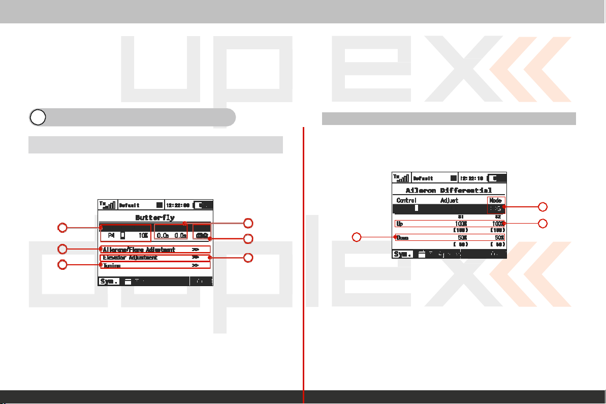
Le
présent appareil est conforme aux CNR d'Industrie Canada
applicables aux appareils radio exempts de
est autorisée aux deux conditions suivantes : (1) l'appareil ne
pas produire de brouillage, et (2) l'utilisateur de l'appareil
accepter tout brouillage
est susceptible d'en c
computer
radioélectrique
ompr
omettre le fonctionnement.
radio
lic
ence. L'exploitation
subi, même si le brouillage
12 Model Menu – Airplane/S
ailplane
12.1 Butterfly
Butterfly/Crow mixing is available with wing configurations of
ailerons servos or
You can find the
a
d
f
Mix (Cr ow
more.
Butterfly
Mix)
menu in “Fine T
uning,
>Butterfly”.
a. Switch
b.
c.
d.
e.
f.
Programming can be set according to specific wing and tail type
5.
assig
Delay of
F
light
mode setting c
Aileron
F
lap
travel
Elevator
nment for butterfly
deployment
travel
setting
setting
travel
setting
or retraction
onfiguration
mix func
func
tion
tion
control
b
c
e
system
doit
doit
2
12.2 A
Aileron
servos or
You can find the
Differential”.
ileron
Diff
erential is
more.
c
Differen
Aileron Differential
tial
available with wing configurations of 2 ailer
menu in
“Fine Tuning, >Aileron
EN
a
b
a. Flight
b.
c.
mode setting c
Aileron„Up“
Aileron„Down“
travel
setting
travel
onfiguration
setting
The aileron differential function reduces the downward travel of
aileron(s) to help eleminate any adverse yaw
maneuv
position induce higher drag than when the aileron is in the
position.
ers. Semi-Symmetrical airfoils with an aileron in the down
tendencies
in rolling
ons
the
up
5.
Page 98

c
onfigurations. For example if your model has “Wing
Ailerons” and standard tail configuration.
be setup to raise the ailerons
(c
ompensation).
computer
(spoilers)
radio
The
and also to raise the
Butterfly
control
function
Type: 2
can
elevator
system
EN
5.
5.
Page 99
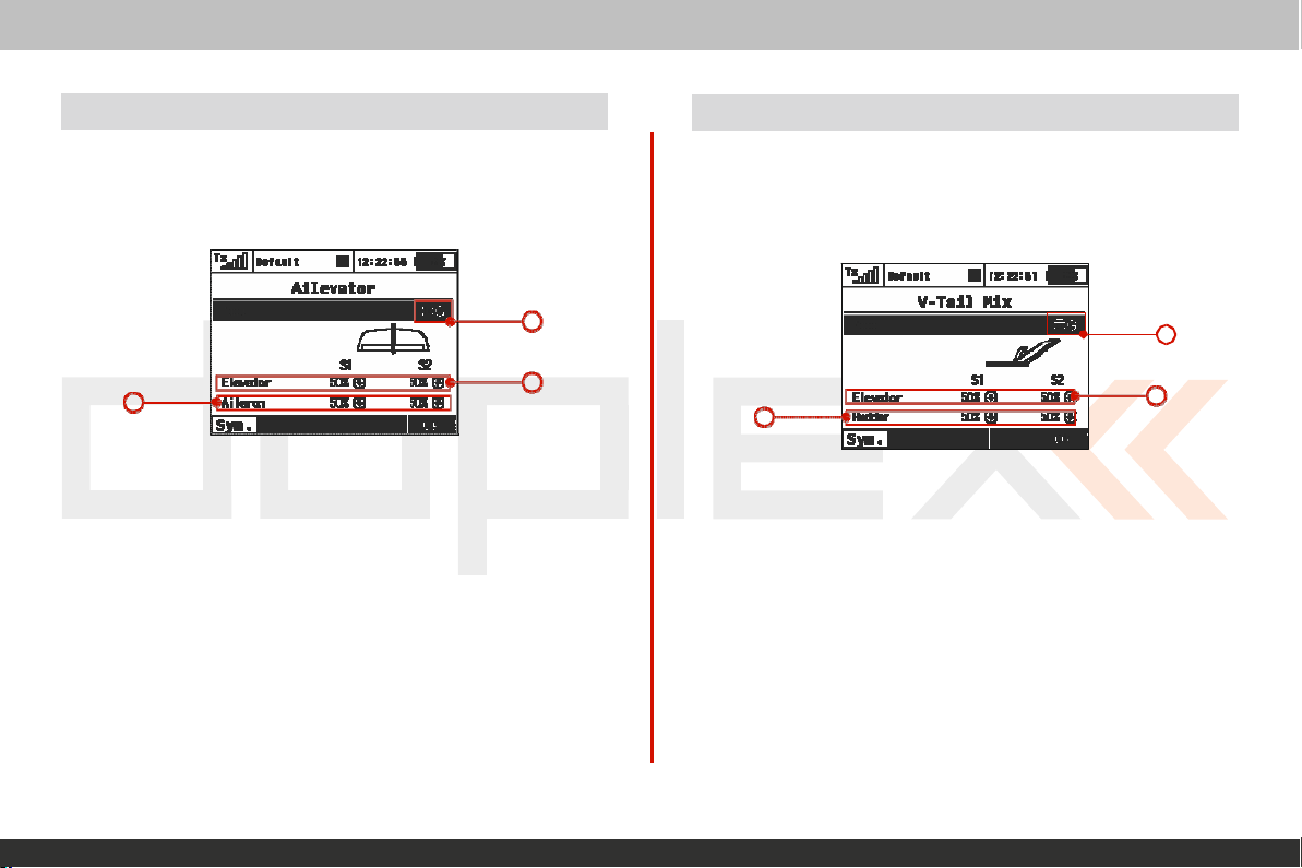
computer
radio
A
12.3
The ailevator function uses two servos
sides can be prog
If
you have this selected as your
Ailevator
ilevator
menu in “Fine T
rammed
to be controlled
uning, >Ailevator”.
for
the elevator
independently.
model’s
tail type, you can find
c
a. Flight
b.
c.
Y
our model’s r
To
disable the mix, set your
both elevator surfaces to move only when the elevator stick is
moved.
mode setting c
Elevator
Aileron
travel
setting
travel
setting
oll
sensitivity is
onfiguration
sig
„Aileron“
nificantly greater with this mix.
throw to zero. This will
control
channel.
a
b
Both
the
cause
system
12.4
V-Tail
The
V-Tail
elevator function and the rudder function. See chapter
If
you have this selected as your
T
ail
menu in “Fine T
Mix
mix function uses two tail servos to control both
model’s
tail type, you can find the V-
uning” -> “V- Tail”
c
a. Flight
b.
c. Rudder travel
mode setting c
Elevator
travel
setting
setting
onfiguration
9.2.8
EN
the
a
b
5.
5.
Page 100
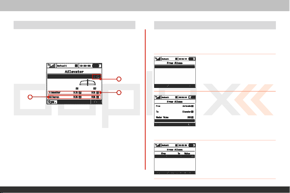
computer
radio
control
system
EN
12.5 Delta/Elevon Mix
The Delta/Elevon
elevator and aileron
Delta type aircraft.
If
you have this selected as your
Delta/Elevon menu
a. Flight
b.
c.
c
mode setting c
Elevator
Aileron
travel
travel
Mix
uses two servos for the control of both
func
tions.
This
mix is most commonly used for
model’s
tail type, you can find
in „F
ine T
setting
setting
uning, >Delta/Elevon“.
onfiguration
12.6 Spoilers to Elevator Mix
the
the
a
b
For models
compensate
spoilers are
this c
ompensation.
equipped
for any pitching
deployed. You
with
1. From inside the
mixes“
to create a new mix.
2. In
“Spoiler” input function as the
function and in the „To“ line select
“Elevator” for your slave function. The
“Master Value”
of elevator travel as it relates to the
travel. Press
3.
To
and press the
the selected
spoilers, the elevator is often used to
tendancies generated
can use one of the free mixers to set
„Fine
menu, press the
the „From“ menu
“F5
(Next)”to save the mix.
edit the mix simply highlight the mix
“F4 (Edit)”
mix’s
„F2 (Add)“
represents
advanced
when
Tuning>Free
line,
select
the
percentage
button
menu.
butt
mast
spoiler
to go
the
up
the
the
int
on
er
o
5.
5.
 Loading...