

Page 1

Certification Exhibit
FCC ID: ONTJETIR900US
IC: 10491A-JETIR900US
FCC Rule Part: 15.247
ISED Canada’s Radio Standards Specification: RSS-247
TÜV SÜD Project Number: 72128518
Manufacturer: Esprit Model Inc.
Model: JETIR900US
3998 FAU Blvd., Suite 310, Boca Raton, FL 33431, Phone: 561-961-5585
Manual
Page 2

computer radio control system
®
User Manual ... 01User Manual ... 01User Manual ... 01
Bedienungsanleitung ... 27Bedienungsanleitung ... 27Bedienungsanleitung ... 27
EN
DE
Receivers REXReceivers REX
FW 1.00FW 1.00
Receivers REX
FW 1.00
Empfänger REXEmpfänger REX
FW 1.00FW 1.00
Empfänger REX
FW 1.00
COMPLEX RADIO CONTROL SYSTEM
Page 3

computer radio control system
1. Introduction ......................................................................................... 03
2. Technical data ...................................................................................... 04
3. Installation ........................................................................................... 05
3.1 Voltage Supply ........................................................................... 05
3.2 Operation ..................................................................................... 05
3.3 Binding .......................................................................................... 06
4. Real Time Telemetry ........................................................................... 08
4.1 EX Telemetry ................................................................................. 08
4.2 - 1st Generation ........................................................................... 08
5. Receiver setup ..................................................................................... 09
5.1 Receiver Setup via the JETIBOX ................................................ 09
5.1.1 Direct connection between a JETIBOX and the
receiver ............................................................................... 09
EN
ENGLISH
1
Page 4

computer radio control system
5.1.2 Wireless connection between a JETIBOX with
transmitter or DC/DS transmitter and the receiver ..... 09
5.2. Receiver set-up via the DC/DS transmitter ............................ 10
6. Receiver Menu ......................................................................................... 11
6.1 Overview of receiver data items ............................................ 11
6.2 Measure ....................................................................................... 11
6.3 Main setting ................................................................................. 12
6.4 Out pin set .................................................................................... 15
6.5 Auto set ......................................................................................... 18
7. Receiver update ...................................................................................... 19
8. Examples of Rx setup ........................................................................... 20
EN
2
Page 5

computer radio control system
JETI Duplex receivers are designated for use with the DC/DS
transmitters or the JETI transmitter modules in the 2.4 GHz
frequency band.
The system is continuously improved. Thanks to online updates the
improvements are easily accessible to users from any part of the
world. From the very beginning bidirectional transmission has
been a distinctive feature of the Duplex system, this not only
handles telemetry data, but it also helps to ensure secure primarily
transmission safety between the transmitter and receiver.
The Duplex EX telemetry system uses an open protocol. This gives
the advantage of compatibility with a large number of telemetry
sensors from both JETI model and third party producers. For the
display of telemetry data you can use purposely designed
equipment like the JETIBOX profi and DC/DS transmitters or
you can display the data on PCs.
Although our development of the Duplex system seems to be very
fast, we make the extra effort to keep backward compatibility with
REX Receivers
1 Introduction
ENGLISH
FW. ver. 1.00
EN
3
Page 6
computer radio control system
earlier Duplex versions. By design, users are not forced to
continually buy new equipment to take advantage of the latest
improvements.
The JETI model company portfolio contains a diverse offering of
electronic modelling equipment like voltage regulators, motor
speed controllers, telemetry data display equipment, telemetry
sensors and, last but not least, DC/DS transmitters. The JETI
model product manfacturing policy is to constantly produce the
highest quality product possible.
EN
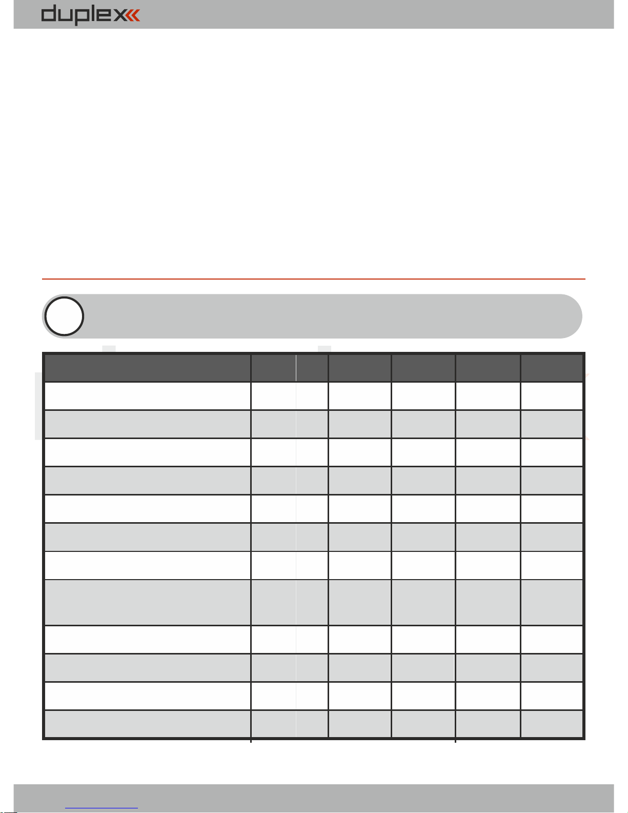
2 Technical data
Basic Data
REX3
REX7 REX10
REX12*
Dimensions [mm]
38x25x11
42x28x11
51x28x11
51x28x11
1
Weight [g]
11 13
16
24
Antenna length [mm]
2x100
2x200
2x200 2x400
# of channel outputs
3
7
10 12
Temperature range [°C]
-10 to +85
-10 to +85 -10 to +85
-10 to +85
Supply voltage [V]
3.5 – 8.4 3.5 – 8.4 3.5 – 8.4 3.5 – 8.4
Average current [mA]
75
75 75 75
Real time transmission
of telemetry data
Yes Yes
Yes Yes
Programming
JETIBOX JETIBOX JETIBOX
JETIBOX
Support satellite receiver Rsat
Yes Yes Yes Yes
Power output [dBm]
15 15
15
15
Receiver sensitivity [dBm]
-106
-106
-106 -106
* xternal ower onnector E P C
4
REX3 900MHz
38x25x11
11
2x100
3
-10 to +85
3.5 – 8.4
75
Yes
JETIBOX
Yes
16
-106
*Warning: The Rex 3 900MHz Receiver can not be
used as primary receiver. It is designed as a backup only!
Page 7

computer radio control system
3.1 Voltage supply
When designing the on-board wiring for your project, always pay
attention to the voltage input range of your receivers and servos.
You can connect supply voltage to the Duplex receivers as
follows:
- directly from the batteries
- via a BEC voltage regulator (either contained in speed
controllers or self contained)
The supply may be connected to the Duplex receivers via:
- the throttle channel (when applying speed controllers with BEC)
- a free receiver output.
- a Y-cable to any arbitrary receiver output
- the MPX connector for receivers with the EPC label which are
equipped with a power supply connector
3.2 Operation
We recommend that you switch on the transmitter first and then
subsequently the receiver. The transmitter confirms the switchingon of the receiver with an acoustic signal. When switching off the
system we recommend that you switch off the receiver first and
then subsequently proceed with switching-off the transmitter.
3 Installation
EN
5
Page 8

computer radio control system
3.3 Binding
When using a new receiver or transmitter it is necessary to carry out
the binding process between them. Transmission between the
receiver and transmitter occurs in fully digital manner, therefore it is
necessary to identify and share the addresses of each device
communicating on the mutual 2.4GHz frequency band.
Procedure:
1. Insert the BIND PLUG (included in the receiver packing) into the
receiver socket labeled Ext.
2. Switch on the receiver – (connect a proper voltage supply to the
receiver). Binding of the receiver may now be performed within 60
seconds. After the 60 seconds elapse the receiver returns to setup
mode and the binding process must be repeated by starting again
from step 1.
3. Switch on the transmitter - the transmitter emits an acoustic
signal announcing the detection of a new receiver.
Binding may be carried out with the aid of the JETIBOX instead of
using the BIND PLUG.
The procedure is as follows:
1. Connect the JETIBOX with the connecting cable to the Ext.
receiver output .
2. Switch on the receiver - (connect a proper voltage supply to the
receiver).
3. The receiver menu appears on the JETIBOX display. Select the
„Pairing“ menu item (push the right arrow button once from the
main receiver display) and then push the upward button. You now
have a period of 60 seconds to bind the receiver. After the 60
EN
6
Page 9

computer radio control system
seconds elapse the receiver returns to setup mode and the binding
process must be repeated by starting again from step 3.
If the binding process between receiver and transmitter was
unsuccessful, try again.
You may bind an arbitrary number of receivers to one transmitter.
The receiver, however, can only be bound to one transmitter, i. e. the
receiver is only bound to the most recently bound transmitter.
As long as the BIND PLUG is inserted into Ext. input, the receiver is
always in „Normal“ mode, regardless your actual receiver setup.
After BIND PLUG is removed, the receiver returns to your selected
setup mode.
EN
7
Page 10

computer radio control system
Every receiver is able to transmit the actual voltage supplied to the
on-board system (i. e. receiver voltage) without the need to connect
any additional external sensors. If you want to take advantage of
extended telemetry, connect a telemetry sensor to the Ext. input of
the receiver. If you want to operate several telemetry sensors
simultaneously with one receiver, you must use one or more of the
Expander EX devices, which , when connected to the Ext. receiver
input, gives you multiple inputs for telemetry sensors.
There are two ways to use JETI telemetry. The EX telemetry is
available to owners of the JETI DC/DS transmitters or the
JETIBOX profi. The 1st Generation Telemetry can be used by
owners of the TU, TG, TF etc. transmitter modules.
4.1 EX Telemetry
This telemetry data is displayed according to user selections in the
DC/DS transmitters and the JETIBOX profi. You will find more
details in actual instruction manuals of the given Duplex EX
equipment.
4.2 - 1st Generation
Connect the JETIBOX to the transmitter module. Switch on the
transmitter and connect the receiver voltage supply (see chapter
„Voltage supply“). The Tx heading appears in the JETIBOX display
and by pressing the push-button R (right button) twice, select the
Mx menu. By pressing the push-button D (down) you will enter the
telemetry sensor or expander menu. You may leave the telemetry
sensor menu by pressing the push-button U(up) slightly longer.
4 Real time telemetry
EN
8
Page 11

computer radio control system
5.1 Receiver setup via the JETIBOX
There are two receiver setup modes. The first is receiver setup via
the JETIBOX, JETIBOX profi or JETIBOX emulation in the DC/DS
transmitters, the second one is direct setup of the receiver with a
DC/DS transmitter.
5.1.1 Direct connection between a JETIBOX and the
receiver
Insert one end of the connection cable (included with the JETIBOX)
into the socket labeled Impuls + - (see the right side of the JETIBOX)
and the other end into the receiver socket labelled Ext. Connect a
voltage supply to the receiver (see Voltage supply) or to the supply
socket of the JETIBOX. There is no need to supply voltage when
using the JETIBOX profi.
5.1.2 Wireless connection between a JETIBOX with
transmitter or DC/DS transmitter and the receiver
In this case, connect the JETIBOX with the transmitter (if you are
using a DC/DS transmitter, then select the JETIBOX emulation).
Switch on the transmitter and then connect the receiver voltage
supply. The Tx heading appears on the display along with right and
down arrows. In order to enter the receiver, press the R button
(right), the Rx heading appears on the display and by subsequently
pressing the D button (down) you enter the receiver menu, which
will be displayed just the same as the direct connection mode (see
5 Receiver setup
EN
9
Page 12

computer radio control system
paragraph 5.1.1). Wireless connection is only possible when a
receiver is in“Normal“ mode (MeasureOrSetting->Main Setting -
>Rx mode: Normal).
The JETIBOX can be disconnected only after you disconnect the
receiver voltage supply. You may monitor the on-board state of
your receiver during your model‘s operation. Pay particular
attention, of course, to your setup work. If it is possible, we do not
recommend changing setup parameters during model
operation. Set-up work should only be done if there is no danger
of damaging the model or injuring people. For safety reasons
prevent motor activation or remove the propeller!
5.2 Receiver set-up via the DC/DS transmitter
Please see information concerning receiver set-up via transmitters
in the DC/DS transmitter instruction manual. You can find the
DC/DS instructions on the manufacturer‘s website.
EN
10
Page 13

computer radio control system
6 Receiver menu
6.1 Overview of receiver data items
The introductory display shows the receiver type. By pushing the R
key (arrow down) more detailed data of receiver and transmitter
can be displayed.
Pairing - by pushing the U key (arrow up) pairing of the receiver
with the transmitter will be executed. Pairing of the receiver should
only be carried out when JETIBOX is directly connected to the
receiver.
RX/TX- RX item shows the unique production number of the
receiver. The TX item shows the unique production number of the
transmitter, to which the receiver has eventually been paired.
Rx Diag- A1 or A2 item shows which antenna the receiver is using at
present. Kx item informs about the number of transferred channels
(this number depends on the transmitter abilities).
By means of the D key (arrow down) you arrive at the line of basic
mode selections, where you may select read out of measured
values (Measure) or setup of the receiver (Main setting, Out Pin
Set, Auto Set).
6.2 Measure
Measure - enables read out of measured data of the maximum,
minimum, and actual receiver voltage.
Volt Min / Act / Max - the receiver is checking the supply voltage
EN
11
Page 14

computer radio control system
and indicates the limit values and extremes which occurred during
operation; at the same time it also shows the actual receiver
voltage. Without switching on the paired transmitter the values
MAX and MIN will not change, only the value of the actual voltage
ACT will be updated. In order to delete MAX and MIN values, keys L
(arrow left) and R (arrow right) must be pressed simultaneously.
RX Signal Level - strength of radio signal from Tx to Rx.
6.3 Main Setting
Fail Safe - switches the Fail Safe function on and off. If the Fail Safe
function is disabled, there are no signals generated on receiver
outputs in case of signal loss. If the Fail Safe function is activated,
the receiver outputs are generated according to your individual
channel setup selections in case of signal loss („out off“, „hold“,“ fail
safe“).
Signal Fault Delay - the time interval from when the receiver
detects signal loss to when the fail safe control throws are initiated.
After the expiration of this time, the receiver outputs will transfer to
your selected individual channel outputs.
Volt ACT/ALARM - the first item displays the actual receiver supply
voltage, the second value represents the setup threshold level for
alarm purposes. During operation, as soon as the actual voltage
becomes lower than the threshold level, the transmitter emits an
acoustical warning tone.
(This setup is for transmitter modules only. For the DC/DS transmitters,
this alarm is set in the transmitter.)
EN
12
Page 15

computer radio control system
Output Period - output signal period setup (initial setup for the
Autosynchronizing mode with the transmitter). This parameter is
fundamentally influencing servo behaviour. With lower output
period values the reactions (response) of analog servos become
faster, but current consumption increases. With a too low setup
value some servos may even start chattering.
PPM-UDI Mode - data conversion mode can be:
Direct
ź output PPM signal contains data directly from the transmitter,
without conversions and channel mapping
ź conversions and possible channel mapping are applied to
output servo impulses only
ź different channels might be assigned to the PPM signal and
servo output pins
Computed
ź conversions and prospective mappings are applied to output
servo impulses and also to PPM signal
ź servo impulses and PPM signal contain the same information
OutputChannelCnt - setup of generated number of receiver
outputs in PPM. If the receiver receives less channels than selected
in setup, the remaining channels (in Computed mode) will be
replaced by a throw specified by the Fail Safe value for individual
channels. Otherwise, the number of output pulses will be reduced
to the setup number.
EN
13
Page 16

computer radio control system
Rx mode - the working mode of the receiver. Possible choices:
Normal
ź bidirectional communication between receiver and
transmitter
ź select this setup for the model‘s main receiver
ź use the same setup if you use only one receiver in your model
(in case you are using only one Duplex receiver for remote
control)
Clone
ź unidirectional communication
ź if you use several Duplex receivers in the model, for instance in
connection with one transmitter module, then you should
operate one of the receivers in „Normal“ mode and the others
in „clone“ mode
ź the receiver operating in „Normal“ mode is considered to be
the main receiver. One of the transmitter modules is able to
control only one receiver in „Normal“ mode
ź if you want to operate several receivers with only one
transmitter module, you should operate them in „clone“
mode
If you switch the receiver to „clone“ mode, further wireless setup
communication becomes impossible because the receiver is now
communicating only unidirectionally. In order to change the mode
or setup, you have to connect the JETIBOX to the receiver and make
the desired change or switch the receiver back to„Normal“ mode:
1. Insert BIND PLUG into the receiver socket labeled Ext.
2. Switch on receiver
3. Switch on transmitter
4. Execute the desired setup changes, see „Receiver setup“
EN
14
Page 17

computer radio control system
6.4 Out pin set
Setup of the physical receiver outputs.
Set Output pin - selection of output, which goes for the following
setup. The menu item shows, as a decimal number, the throw of the
selected output. Receiver output 1 is labeled as Y1.
Pin Config - receiver pin config can be:
Servo
ź standard impulse output for servos
(-100% = 1ms, 0%= 1,5ms / +100% = 2ms )
Digital
ź the output pin is in a stable LOW condition (log. 0) if the
position of this channel is negative, otherwise this pin is in
HIGH condition (log.1)
ź ensure that pin is used only as logical output, don't draw the
current above 1mA
Input
ź here the pin is configured as an input and its condition
(disconnected/connected to the ground) is sent to the
transmitter as other telemetry data from the sensors
ź it is allowed to keep the pin disconnected or connected to the
common ground of the receiver
ź it is not allowed to connect to a different voltage. The pin
works exclusively in PullUp mode so all you need to test the
function is to connect the signal pin to the ground.
PPM pos.- standard form of PPM signal generation with
positive logic at PPM outputs. The bus idle state is log. 0.
EN
15
Page 18

computer radio control system
PPM neg.- standard form of PPM signal generation with
negative logic at PPM outputs. The bus idle state is log.1.
PPM input - for the given input there a PPM signal is expected
from the connected receiver
JETIBOX EX - telemetry sensor connection or data stream for
JETIBOX
EX Bus/EX Bus HS - digital communication, when transmits
throw and telemetry information with configuration
possibilities of equipment connected to this bus, for instance by
a DC/DS transmitter. This configuration type is used, for
instance, when receivers are connected for example to Central
Box.
Serial UDI12/16 - serial data output suitable for connection of
devices with unidirectional UDI interface (e.g. Vbar).
PPM error code- in case of PPM input mode, an acoustic signal can
be set up to announce that this connected signal is missing. By
loading a character from the Morse alphabet you may set up tones
that will acoustically announce the absence of a PPM signal at the
given receiver output. This acoustical signal is generated by the
transmitter module. In the factory default setup the acoustical
signal is switched off.
SetInChannel - assignment of an actual output (labelled as Yx) or
input channel (labelled as Chx)
EN
16
Page 19

computer radio control system
Output Trim - neutral throw setup for receiver output
Gain A - amplification of the output throw in the negative half-plain
A (from -150 to 0%)
Gain B - amplification of the output throw in the positive half-plain
B (from 0% to 150%)
Signal Fault - setup of the receiver behaviour in case of signal loss,
„hold“- holds the most recent control throw, „out off“ – output
switch-off (no signal generated), „failSafe“ – moves to preset throws
for the individual outputs
FS position - FailSafe output position in case of signal loss
FS speed - sets how quickly the throws move to the FailSafe
positions in case of signal loss
Output Group - setup of given output into a selected group of
output pulses, which will be simultaneously generated by the
receiver.
EN
17
Page 20
computer radio control system
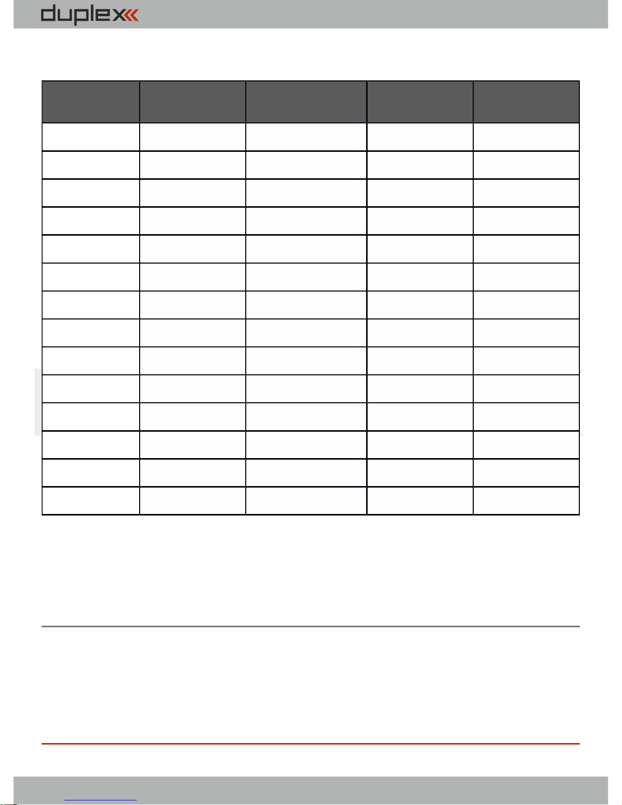
REX 6
REX 7
REX 10
REX 12
Pin1
Y1
Y1
Y1
Y1
Pin2
Y2
Y2
Y2
Y2
Pin3
Y3
Y3
Y3
Y3
Pin4
Y4
Y4
Y4
Y4
Pin5
Y5/E1
Y5
Y5
Y5
Pin6
Y6/E2
Y6/E1
Y6
Y6
Pin7
Ext.
Y7/E2
Y7
Y7
Pin8
Ext.
Y8/E2
Y8/E2
Pin9
Y9
Y9
Pin10
Y10
Y10
Pin11
Bat.
Y11
Pin12
Bat.
Y12
Pin13
E1
E1
Pin14
Ext.
Ext.
Assignment table of receiver outputs:
• - Output types:
Y - servo output, dig. out, dig. input
E1,2 - JETIBOX-EX, PPM out, PPM input, EX-Bus, UDI
Ext. - JETIBOX-EX
6.5 Auto set
Loads a default receiver configuration from preset modes.
Factory default - to reset receiver to the factory settings press and
hold keys L and R simultaneously.
18
Page 21
computer radio control system
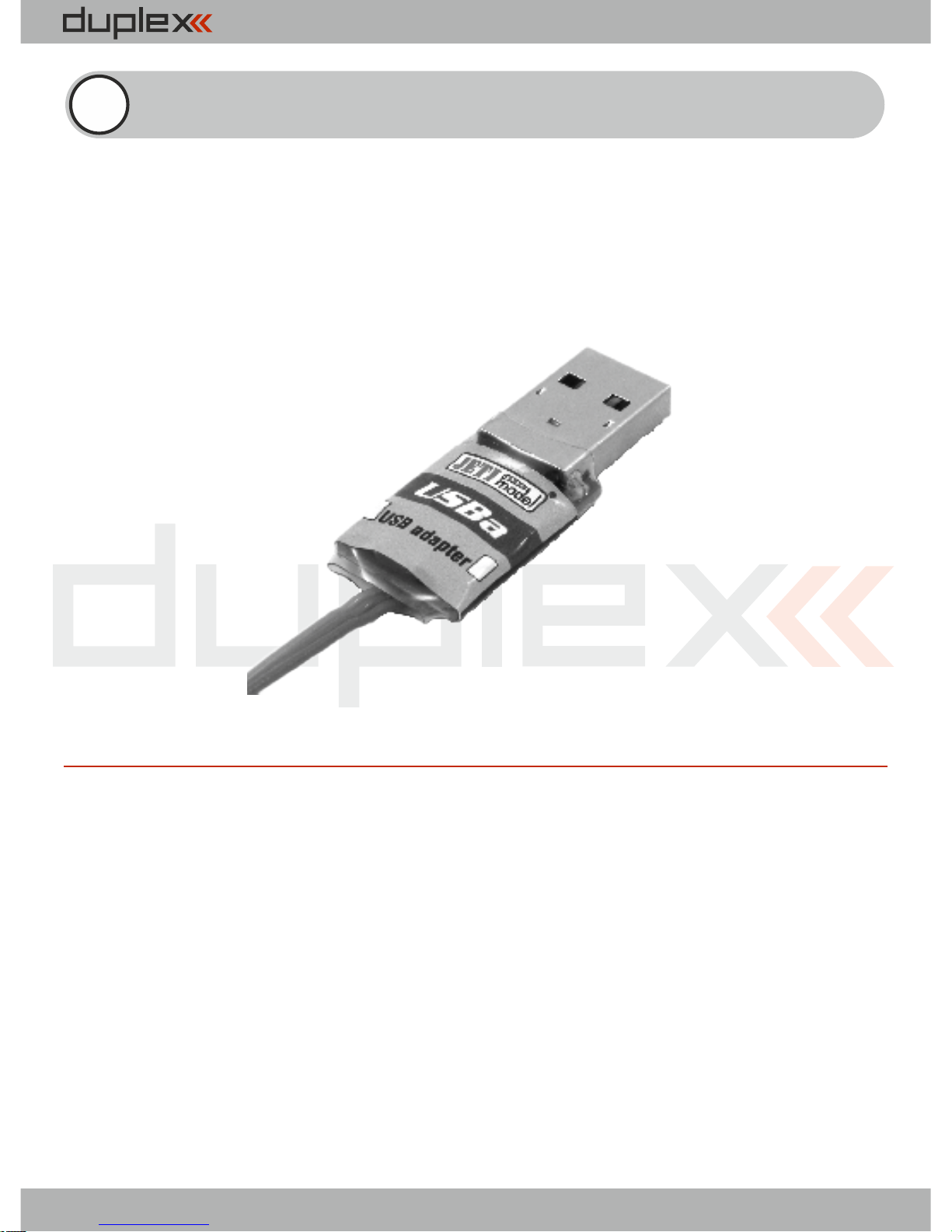
Duplex REX receivers can be updated via PC with the aid of the JETI
USB adapter. You may find a detailed description of the receiver
update process in the USB adapter instruction manual.
7 Receiver update
USB adapter
EN
19
Page 22
computer radio control system
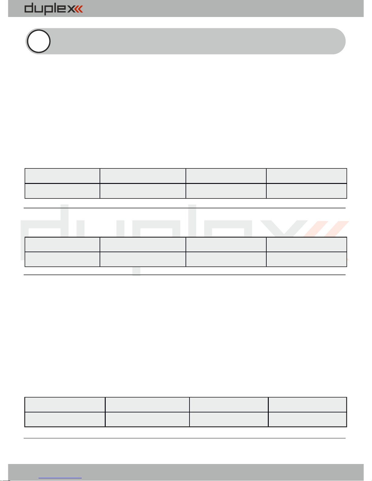
Classic setup of a single receiver
(for any analogue/digital servos)
- servo impulses are generated on servo outputs
- each output can be assigned to one of the groups from A to H
- servo outputs assigned to one group are generated at the same
time
- between two consecutive servo groups there is a delay of 2.5ms
8 Examples of Rx setup
FailSafe
SignalFaultDealy
OutputPeriod
Rx mode
Enabled
1.5s
17 ms
Normal
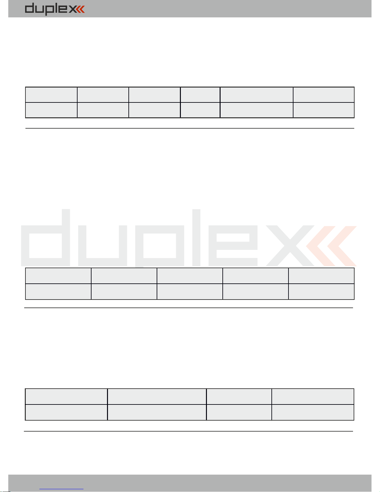
Classic setup of a single receiver (for digital servos)
FailSafe
SignalFaultDealy
OutputPeriod
Rx mode
Enabled
1.5s
Auto
Normal
The second receiver as a backup (clone mode)
- monitors existing connection between the transmitter and the
receiver in "Normal" mode
- does not support telemetry (or an indication of the signal
strength)
- works in receiving direction only, it never transmits
- any number of receivers in Clone mode can be operated
simultaneously
FailSafe
SignalFaultDealy
OutputPeriod
Rx mode
Disabled
1.5s
17 ms (or Auto)
Clone
20
Page 23
computer radio control system
Receiver with the PPM output
- possibility to select PPM pos./neg.
- PPM output can be selected on E1 or E2 output
FailSafe
OutputPeriod
E1 or E2
Rx mode
OutputChannelCnt
PPM Mode
Enabled
20 ms
PPM pos.
Normal
8
Direct
Receiver with the PPM output in the function of
backup receiver
- PPM output can be selected on E1 or E2 output
- no output repetition or fail safe is carried out. Every time the
receiver gets the data packet, output impulses and PPM burst
are generated once maximally
- if the data from the transmitter is not available for the receiver, all
the outputs are in Out-Off mode
FailSafe
OutputPeriod
E1 or E2
Rx mode
PPM Mode
Disabled
Auto
PPM pos.
Normal
Direct
Receiver with the EX Bus output
- suitable especially for connection to JETI model devices (such as
Central Box)
- EX Bus can be selected on E1 or E2 output
FailSafe
OutputPeriod
E1 or E2
Rx mode
Enabled
17 ms (or Auto)
EX Bus
Normal
21
Page 24
computer radio control system
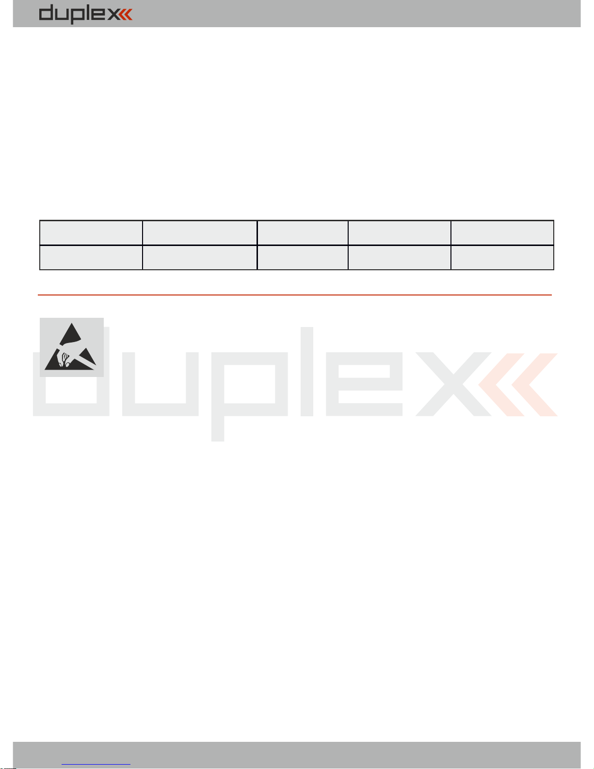
Receiver with the UDI output
- suitable for connection of devices with unidirectional UDI
interface (e.g. VBar)
- UDI output can be selected on E1 or E2 output
- the servo impulses are generated on other servo outputs, it is
possible to connect telemetry sensors to the Ext. connector as
usual
FailSafe
OutputPeriod
E1 or E2
Rx mode
UDI Mode
Enabled
17 ms (or Auto)
UDI12
Normal
Direct
We wish you sucessful flying with the products of:
JETI model s.r.o. Příbor, www.jetimodel.com
For receivers we grant a warranty of 24 months from the day of
purchase under the assumption that they have been operated
in conformity with these instructions at recommended
voltages and that they were not damaged mechanically.
Warranty and post warranty service is provided by the
manufacturer.
ELECTROSTATIC SENSITIVE DEVICE
OBSERVE HANDLING PRECAUTIONS
22
Page 25
computer radio control system
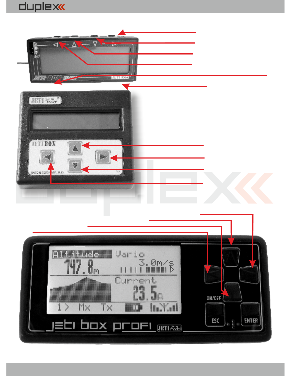
Button right
Button down
Button up
Button backlight
Button for switching input Ext./Tx
Button left
Button UP U
Button RIGHT R
Button DOWN D
Button LEFT L
Button UP
Button RIGHT
Button DOWN
Button LEFT
JETIBOX mini
JETIBOX
JETIBOX profi
EN
23
Page 26

computer radio control system
EN
24
Page 27

computer radio control system
EN
25
• Reorient or relocate the receiving antenna.
• Increase the separation between the equipment and receiver.
• Connect the equipment into an outlet on a circuit different from that to which the receiver is
connected.
• Consult the dealer or an experienced radio/TV technician for help.
FCC /IC Information
This equipment has been tested and found to comply with the limits for a Class B digital device,
pursuant to Part 15 of the FCC Rules. These limits are designed to provide reasonable
protection against harmful interference in a residential installation. This equipment
generates, uses, and can radiate radio frequency energy and, if not installed and used in accordance
with the instructions, may cause harmful interference to radio communications. However, there
is no guarantee that interference will not occur in a particular installation. If this
equipment does cause harmful interference to radio or television reception, which can
be determined by turning the equipment off and on, the user is encouraged to try to correct the
interference by one or more of the following measures:
Page 28

computer radio control system
EN
26
THIS DEVICE COMPLIES WITH PART 15 OF THE FCC RULES. OPERATION IS SUBJECT TO THE
FOLLOWING TWO CONDITIONS (1) THIS DEVICE MAY NOT CAUSE HARMFUL INTERFERENCE, AND
(2) THIS
DEVICE MUST ACCEPT ANY INTERFERENCE RECEIVED, INCLUDING INTERFERENCE THAT MAY
CAUSE UNDESIRED OPERATION
Warning: Changes or modifications to this device not expressly approved by Esprit
Model/JETI USA could void the user’s authority to operate the equipment. “This
equipment complies with radiation exposure limits set forth for an uncontrolled environment. This
equipment should be installed and operated with minimum distance 20 cm between the
radiator and your body. This transmitter must not be co-located or operating in conjunction
with any other antenna or transmitter.”
Under Industry Canada regulations, this radio transmitter may only operate using an antenna of a type
and maximum (or lesser) gain approved for the transmitter by Industry Canada. To
reduce potential radio interference to other users, the
antenna type and its gain should be so
chosen that the equivalent isotropically radiated power (e.i.r.p.) is not more than that necessary for
successful communication.
Conformément à la réglementation d'Industrie Canada, le présent émetteur radio peut
fonctionner avec une antenne d'un type et d'un gain maximal (ou inférieur) approuvé pour
Dans le but de réduire les risques de brouillage
autres utilisateurs, il faut choisir le type d'antenne et son gain de
rayonnée équivalente (p.i.r.e.) ne dépasse pas l'intensité
l'émetteur par Industrie Canada.
radioélectrique à l'intention des
sorte que la puissance isotrope
nécessaire à l'établissement d'une communication satisfaisante.
This device complies with the Industry Canada license-exempt RSS standard(s). Operation
is subject to the following two conditions: (1) this device may not cause interference, and (2)
this device must accept any interference, including interference that may cause
undesired operation of the device.
Le présent appareil est conforme aux cnr d'Industrie Canada applicables aux appareils radio
exempts de licence. L'exploitation est autorisée aux deux conditions suivantes
:
(1) l'appareil ne doit pas produire de brouillage, et (2) l'utilisateur de l'appareil doit accepter tout
brouillage radioélectrique subi, même si le brouillage est susceptible d'en
compromettre le fonctionnement.
Cet équipement est conforme aux limites d'exposition aux radiations dans un environnement non
contrôlé. Cet équipement doit être installé et utilisé à distance minimum de 20 cm* entre le radiateur et
votre corps. Cet émetteur ne doit pas être co-localisées ou opérant en conjonction avec tout
autre antenne ou transmetteur.
Page 29

computer radio control system
1. Einleitung ......................................................................................... 27
2. Technische Daten ............................................................................... 29
3. Übersicht ............................................................................................... 30
3.1 Spannungsversorgung ............................................................ 30
3.2 Betrieb ........................................................................................... 30
3.3 Bindevorgang .............................................................................. 31
4. Echtzeittelemetrie ........................................................................... 32
4.1 EX Telemetrie ............................................................................... 33
4.2 Telemetrie der 1.Generation .................................................... 33
5. Empfängersetup ................................................................................ 34
5.1 Empfängereinstellungen über die JETIBOX .......................... 34
5.1.1 Direktverbindung zwischen der JETIBOX und dem
Empfänger .......................................................................... 34
DE
DEUTSCH
27
Page 30

computer radio control system
5.1.2 Drahtlose Verbindung zwischen einer JETIBOX am
Sender oder einem DC/DS-Sender und dem
Empfänger............................................................................ 34
5.2. Empfängereinstellung mit DC/DS-Sender ............................ 35
6. Empfängermenü .................................................................................... 36
6.1 Übersicht der Empfänger
Programmiermöglichkeiten .................................................... 36
6.2 Messen/Anzeigen (Measure) .................................................... 36
6.3 Main Setting ................................................................................. 37
6.4 Out Pin Set .................................................................................... 40
6.5 Auto Set ........................................................................................ 44
7. Empfängerupdate ................................................................................ 44
8. Empfänger-Setup Beispiele .............................................................. 45
DE
28
Page 31

computer radio control system
REX Empfänger
1 Einleitung
DEUTSCH
FW. ver. 1.00
DE
JETI Duplex Empfänger werden in Kombination mit den
JETI DS/DC-Sendern oder den JETI Sendemodulen
verwendet und im 2,4GHz Band betrieben.
Während der Weiterentwicklung des Systems wurden auch
die Rückmeldungen der Anwender berücksichtigt, die
Aktualisierungen können mittels online verfügbarer
Updates weltweit und selbständig durchgeführt werden.
Bereits vom Anfang an war die bidirektionale Übertragung
ein integraler Bestandteil des Duplex-Systems, diese wird
nicht nur zur Übertragung der Telemetriedaten sondern
a u c h z u r E r h ö h u n g d e r e i g e n t l i c h e n
Übertragungssicherheit zwischen Sender und Empfänger
verwendet.
2
9
Page 32

computer radio control system
DE
Das Duplex EX Telemetriesystem verwendet ein offenes
Protokoll, wodurch die Kompatibilität zwischen einer
gro ß en Ausw a hl von J E T I - S enso r en und auch
Fremdprodukten gewährleistet ist. Die Anzeige der
Telemetriedaten kann direkt auf den DS/DC-Sendern oder
auf speziellem Zubehör wie der JETIBOX profi erfolgen. Die
Anzeige der Telemetriedaten kann direkt auf den DS/DCSendern oder auf speziellem Zubehör wie der JETIBOX profi
oder auf PC mit USB Adapter erfolgen.
Trotz der raschen Weiterentwicklung des Duplex-Systems
haben wir uns besonders um die Abwärtskompatibilität mit
früheren Versionen bemüht. Durch dieses Systemdesign ist
k ein A nwender gez w u n g e n , p e r m a n e n t n e u e
Komponenten zu k aufen um von den aktuellen
Systemerweiterungen zu profitieren.
Das Gesamtangebot von JETI model s.r.o. beinhaltet eine
breite Palette an elektronischem Zubehör wie
Spannungsregler, Drehzalsteller, Zubehör zur
Telemetriedatenanzeige, Telemetriesensoren und nicht
z u l e t z t d i e D C / D S - S e n d e r l i n i e n . D i e
Produktionsphilosophie von JETI model s.r.o ist es, die
höchstmögliche Produktqualität durchgehend zu
gewährleisten.
30
Page 33
computer radio control system
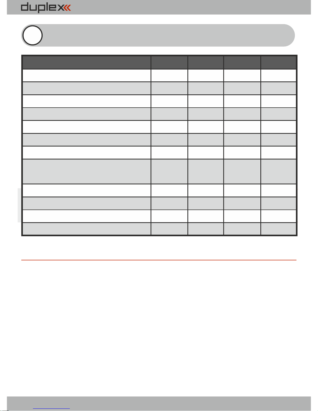
2 Technische Daten
Bezeichnung
REX6
REX7
REX10
REX12*
Abmessungen[mm]
38x25x11
42x28x11
51x28x11
51x28x11
Gewicht [g]
111316
24
Antennenlänge [mm]
2x100
2x200
2x200
2x400
Anzahl der Ausgangskanäle
6
71012
Betriebstemperatur [°C]
-10 bis +85
-10 bis+85
-10 bis +85
-10 bis +85
Versorgungsspannung [V]
3.5 – 8.4
3.5 – 8.4
3.5 – 8.4
3.5 – 8.4
Mittlerer Stromverbrauch [mA]
75
757575
Übertragung von Telemetriedaten in
Realzeit
Ja
JaJaJa
Programmierung
JETIBOX
JETIBOX
JETIBOX
JETIBOX
Anschlußmöglichkeit für Satellit RSat
Ja
Ja
Ja
Ja
Maximale Ausgangsleistung [dBm]
151515
15
Empfindlichkeit des Empfängers [dBm]
-106
-106
-106
-106
* xternal ower onnector E P C
31
Page 34

computer radio control system
3.1 Spannungsversorgung
Beachten Sie beim Design der Bordverkabelung Ihrer Projekte den
zulässigen Spannungsbereich der verwendeten Empfänger und
Servos.
Sie können Ihre Duplex Empfänger wie folgt versorgen:
- direkt aus den Akkus (zulässigen Spannungsbereich beachten)
- über eine geregelte Spannungsversorgung mittels BEC des
Drehzahlstellers bzw. eigenständige BEC-Komponenten (zB.
JETI MaxBEC, SBEC,...)
Der Anschluss der Spannungsversorgung an den Duplex
Empfänger erfolgt an:
- den Gaskanal (bei Drehzahlstellern mit BEC)
- einen freien Empfängerausgang.
- mittels Y-Kabel an einem beliebigem Empfängerausgang
- den MPX-Stecker bei „EPC“ wenn die Versorgung durch eine
externe Stromversorgung (Akku, BEC) und nicht durch das
Regler-BEC erfolgt
3.2 Betrieb
Wir empfehlen, zuerst den Sender und danach den Empfänger
einzuschalten. Der Sender bestätigt die Inbetriebnahme des
E m p f ä n g e r s m i t e i n e m a k u s t i s c h e m S i g n a l . A l s
Ausschaltreihenfolge empfehlen wir zuerst den Empfänger und
danach den Sender auszuschalten.
3 Übersicht
DE
32
Page 35

computer radio control system
3.3 Bindevorgang
Bei Verwendung eines neuen Senders oder Empfängers muss
zu erst d er Bin de vorga ng d urch ge fü hr t we rden. Di e
Datenübertragung zwischen Sender und Empfänger erfolgt
digital, daher ist es notwendig, die jeweils eindeutigen Adressen zu
identifizieren und zwischen den 2,4 Ghz Komponenten
auszutauschen.
Ablauf:
1. Stecken Sie den Bindestecker (Bestandteil des Lieferumfanges) in
den Empänger auf den Steckplatz „Ext.“
2. Schalten Sie den Empfänger ein bzw. verbinden Sie diesen mit
einer geeigneten Spannungsquelle. Der Bindevorgang erfolgt
innerhalb von 60 Sekunden. Schlägt der Bindevorgang fehl kehrt
der Empfänger nach 60 Sekunden in den Einstellmodus zurück
und der Vorgang muss wiederholt werden.
3. Schalten Sie den Sender ein – der Sender bestätigt die
Verbindung mit dem neuen Empfänger akustisch.
Der Bindevorgang kann auch ohne Bindestecker mit Hilfe der
JETIBOX durchgeführt werden:
Ablauf:
1. Verbinden Sie die JETIBOX mit dem Ausgang „Ext.“ des
Empfängers - das erforderliche Patchkabel ist im Lieferumfang
der JETIBOX enthalten
2. Schalten Sie den Empfänger ein bzw. verbinden Sie diesen mit
einer geeigneten Spannungsquelle.
3. Das Empfängermenü wird an der JETIBOX angezeigt. Wählen Sie
den Menüpunkt „Pairing“ (aus dem Hauptmenü einmal Taste
DE
33
Page 36
computer radio control system
„rechts“ und dann „aufwärts“ drücken). Danach kann innerhalb
von 60 Sekunden der Empfänger gebunden werden. Schlägt der
Bindevorgang fehl kehrt der Empfänger nach 60 Sekunden in den
Einstellmodus zurück und der Vorgang muss wiederholt werden.
An jeden Sender/Sendemodul kann eine beliebige Anzahl von
Empfänger gebunden werden. Ein Empfänger kann zu einem
Zeitpunkt an genau einen Sender gebunden werden, d.h. die
aktuelle Bindung besteht jeweils zum letzten Sender, an den er
gebunden wurde.
So lange sich der Bindestecker am im Steckplatz „Ext.“ befindet
arbeitet der Empfänger, unabhängig von seiner ursprünglichen
Einstellung, in der Betriebsart „Normal“. Nach dem Entfernen des
Bindesteckers kehrt der Empfänger wieder in seine eingestellte
Betriebsart (Normal/Clone) zurück.
DE
J ede r E m p fän g e r k a n n die a k tue l l e S pan n u ng d e r
Bordstromversorgung (Empfängerspannung) übertragen, ohne
dass weitere Sensoren angeschlossen werden müssen. Um von
weiteren Telemetriewerten zu profitieren müssen Sie den
gewünschten Sensor mit dem Eingang „Ext.“ am Empfänger
verbinden. Wollen Sie mehrere Sensoren gleichzeitig an einem
Empfänger verwenden müssen Sie ein Expander EX Modul
verwenden. Wenn dieses an „Ext „ angeschlossen wird erhalten Sie
zusätzliche Steckplätze für die Sensoren.
4 Echtzeittelemetrie
34
Page 37

computer radio control system
DE
Es gibt grundsätzlich zwei Möglichkeiten zur Verwendung der JETITelemetrie: Die erweiterte EX-Telemetrie kann in Verbindung mit
den JETI DC/DS-Sendern oder der JETIBOX profi verwendet, die
Telemtrie der ersten Generation kann zusammen mit den TU-, TG-,
TF-, … Sendemodulen verwendet werden.
4.1 EX Telemetrie
D i e Te l e m e t r i e d a t e n w e r d e n e n t s p r e c h e n d d e n
Anwendereinstellungen am DC/DS-Sender und der JETIBOX profi
angezeigt. Detailinformationen entnehmen Sie den Anleitungen
der jeweiligen Duplex EX Komponenten.
4.2 Telemetrie der 1.Generation
Verbinden Sie die Jetibox mit dem Sendemodul. Schalten Sie den
S end e r e i n u nd d a nac h d e n E mpä n g er ( → K a p ite l
Spannungsversorgung). Die Überschrift „Tx“ erscheint am JETIBOX
Display, zweimal Tastendruck „rechts“ wechselt in das Mx-Menü.
Durch Drücken der „Abwärts-“ Taste D wird das Telemetriesensoroder Expandermenü aufgerufen. Durch längeres Drücken der
„Aufwärts“ Taste U verlassen Sie dieses Menü.
35
Page 38

computer radio control system
5.1 Empfängereinstellungen über die JETIBOX
Es gibt zwei Empfänger Einstell-Modi. Der Erste ist das EmpfängerSetup mittels der JETIBOX, JETIBOX Profi oder JETIBOX Emulation
des DC/DS Senders, oder der zweite Einstellmode ist eine direkte
Einstellung des Empfängers aus dem Menü des DC/DS Senders
(Geräteübersicht).
5.1.1 Direktverbindung zwischen der JETIBOX und dem
Empfänger
Das Verbindungskabel wird in den mit Impuls + - beschrifteten
Eingang der Jetibox und am Empfänger in „Ext.“ gesteckt.
Versorgen Sie den Empfänger mit Spannung (-> Kapitel
S p a n n u n g s v e r s o r g u n g ) o d e r s c h l i e s s e n s i e d i e
Spannungsversorgung (am beschrifteten Eingang + -) direkt an der
JETIBOX an. Bei Verwendung der JETIBOX profi ist keine weitere
Spannungsversorgung erforderlich.
5.1.2 Drahtlose Verbindung zwischen einer JETIBOX am
Sende r o d er einem D C/D S - S ender u nd dem
Empfänger.
In diesem Fall verbinden Sie die JETIBOX mit dem Sender. (Bei
Verwendung eines DC/DS-16 wählen Sie die JETIBOX-Emulation).
Schalten Sie den Sender und danach den Empfänger ein. Das TXMenü erscheint in der Anzeige der JETIBOX/JETIBOX-Emulation) in
Verbindung mit den und - Pfeilen. Um in das „Abwärts“ „Rechts“
5 Empfängersetup
DE
3
6
Page 39

computer radio control system
Empfängermenü zu gelangen drücken Sie die Taste das „Rechts“,
RX-Menü erscheint und durch mehrmaliges Drücken der Taste
„Abwärts“ gelangen Sie in das Empfängermenü (im Punkt A
beschrieben). Die drahtlose Verbindung ist nur möglich wenn der
E m p f ä n g e r i m M o d u s „ N o r m a l “ b e t r i e b e n w i r d
(MeasureOrSetting->Main Setting ->Rx mode: Normal).
Nach dem Entfernen der Empfängerstromversorgung kann die
JETIBOX abgesteckt werden. Sie können den Betriebszustand
des Empfängers auch während dem Betrieb beobachten und
kontrollieren. Nehmen Sie Änderungen der Einstellungen nur mit
besonderer Sorgfalt vor. Obwohl es möglich ist, empfehlen wir
während des (Flug-)Betriebes keine Änderungen der
Einstellungen durchzuführen. Einstellungen dürfen nur
vorgenommen werden wenn dadurch keinerlei Gefahren für
Personen- oder Sachschäden bestehen. Aus Sicherheitsgründen
verhindern Sie ein unvorhergesehenes Anlaufen des Motors oder
nehmen Sie die Luftschraube ab!
5.2 Empfängereinstellung mit DC/DS-Sender
Bitte entnehmen Sie die entsprechenden Informationen der
DC/DS-16 Anleitung – bei Bedarf finden Sie diese auf der
Homepage des Herstellers.
DE
3
7
Page 40

computer radio control system
6 Empfängermenü
6.1 Übersicht der Empfänger
Programmiermöglichkeiten
Das einleitende Display zeigt den Typ des Empfängers. Durch Druck
auf die Taste D (Pfeil unten) werden detailliertere Daten des
Empfängers angezeigt. Das Pairing zum Sender kann durch Druck
einmal Taste R (rechts) und durch längeres Halten der Taste U (Pfeil
nach oben) ausgeführt werden. Dieses Binding sollte nur
durchgeführt werden, wenn die JETIBOX direkt mit dem
Empfänger verbunden ist (nicht drahtlos vom Sender aus!). Ein
weiterer Druck auf die Taste R (rechts) zeigt die Seriennummer des
Empfängers und des gebundenen Senders/Sendemoduls. Wird
dann die Tast R (rechts) nochmals betätigt, zeigt das Display die
Firmwarversion des Empfängers und nach einer weiteren
Betätigung der Taste R (rechts) die Antennenempfangsstärke (A1
und A2) und die übertragene Kanalzahl des Senders.
Mittels der Taste D (Pfeil nach unten) gelangen Sie zu einer
Auswahl der Programmiermöglichkeiten. Hier können zwischen
Auslesen der gespeicherten und aktuellen Messwerte (Measure)
oder Setup des Empfängers, mit den Haupteinstellungen (Main
Setting), Einstellungen der Ausgangssteckplätze (Out Pin Set) und
der Rücksetzmöglichkeit (Auto Set), auswählen.
6.2 Messen/Anzeigen (Measure)
Umin/Uact/Umax: Anzeige der minimalen/aktuellen/maximalen
im Betrieb aufgetretenen Versorgungsspannung des Empfängers
DE
38
Page 41

computer radio control system
Ohne Einschalten des gebundenen Senders sind die Werte MAX
und MIN nicht zu ändern, nur den Wert der tatsächlichen aktuellen
Spannung wird automatisch aktualisiert. Um die MIN/MAX Werte
zu löschen, drücken Sie bitte die Tasten L und R (links + rechts)
gleichzeitig bis die Werte gelöscht sind.
RX Signal Level - Signalstärke von Tx zu Rx.
6.3 Main Setting
Fail Safe - aktiviert und deaktiviert die FailSafe-Funktion. Wird
Failsafe deaktiviert, werden im Fall des Signalverlustes keine
Ausgangssignale am Empfänger generiert. Ist die FailSafe-Funktion
aktiviert, generiert der Empfänger Ausgangssignale entsprechend
Ihrer gewählten Einstellungen bei Signalverlust. („out off“, „hold“,“
fail safe“)
Signal Fault Delay - legt die Zeitspanne zwischen Signalverlust
und Aktivierung der FailSafe-Einstellungen fest. Nachdem diese
Zeitspanne abgelaufen ist werden die Ausgangssignale des
Empfängers entsprechend Ihrer individuellen Kanaleinstellungen
ausgegeben.
Volt ACT/ALARM: der erste Wert beschreibt die aktuelle
Empfängerspannung, der zweite Wert die Einstellung, bei welcher
S pan n u ng d er A lar m a u sge g e ben w i rd. We n n d ie
Empfänge rspan nung im Betrie b die se Alar mschwelle
unterschreitet wird durch den Sender ein akustisches Signal als
Warnton ausgegeben.
(Diese Einstellung hat nur bei der Verwendung von DuplexSendermodulen Auswirkungen. Bei den DC/DS-Sendern erfolgt diese
Einstellung direkt über die Sendersoftware.)
DE
3
9
Page 42

computer radio control system
Output Period - beschreibt den Takt der Ausgabe der Signale am
E m p f ä n g e r a u s g a n g ( I n i t i a l s e t u p f ü r d e n
Autosynchronisierungsmodus mit dem Sender). Diese Einstellung
hat grundlegende Auswirkungen auf das Betriebsverhalten des
Ser vo s. Durc h eine k ürzere O ut pu t Pe ri od wird d as
Ansprechverhalten von Analogservos beschleunig, allerdings der
Stromverbrauch erhöht. Manche Servos neigen bei zu geringen
Werten zum Zittern.
P PM- UD I-Mo dus - di e Da te n kö nn en folg en de rmaße n
ausgegeben werden:
- Direct
- digitaler Ausgang für verschiedene Stabilisierungssysteme
(Universal Digital Interface)
- Ausgabe des PPM Signals direkt vom Sender ohne weitere
Verarbeitung durch den Empfänger (kein e Failsafe -,
Wegeeinstellungen usw)
- mögliche Kanal/Steckplatzzuordnungen werden direkt
ausgegeben
- die verschiedene Kanäle können auf das PPM-Signal und die
Servoausgangssteckplätze zugeordnet werden
- Computed
- digitaler Ausgang für verschiedene Stabilisierungssysteme
(Universal Digital Interface)
- Ausgabe des PPM Signals inkl. weiterer Verarbeitung durch den
Empfänger (Failsafe-, Wegeeinstellungen usw.)
- die verschiedene Kanäle können auf das PPM-Signal und die
Servoausgangssteckplätze zugeordnet werden
- die Servoimpulse und das PPM Signal enthalten die gleichen
Informationen
DE
40
Page 43

computer radio control system
OutputChannelCnt - Anzahl der generierten Empfängerkanäle.
Wird der Empfänger auf weniger Kanäle als in ausgewählten
Sender-Setup programmiert, werden die restlichen Kanäle auf
einen bestimmten Wert (Fail-Safe- Wert) gesetzt.
Rx mode - der Betriebsmodus des Empfängers. Mögliche
Einstellungen:
Normal - bidirektionale Kommunikation zwischen Sender und
Em pf änger. Wählen Sie di es e E in stellun g fü r de n
Hauptempfänger des Modells. Verwenden Sie diese Einstellung
auch falls Sie in Ihrem Modell lediglich einen DuplexEmpfänger für die Steuerung verwenden.
Clone - Unidirektionale Kommunikation. Falls Sie mehrere
Duplex-Empfänger in Ihrem Modell verwenden, z.B. in
Verbindung mit einem Sendemodul muss ein Empfänger im
„Normal“-Modus und alle anderen im „Clone“-Modus arbeiten.
Der Empfänger im „Normal“-Modus ist als Hauptempfänger
vorzusehen. Jedes Sendemodul kann genau einen Empfänger
im „Normal“-Modus ansprechen, alle weiteren, gleichzeitig in
Betrieb befindlichen Empfänger, sind in den „Clone“-Modus zu
versetzen.
Wenn Sie den Empfänger in den „Clone“ -Modus versetzen ist
keine weitere drahtlose Kommunikation mehr möglich, da der
Empfänger nur noch unidirektional kommuniziert („zuhört“). Um
diesen Modus aufzurufen oder die Einstellungen zu ändern
müssen Sie die JETIBOX mit dem Empfänger verbinden – oder den
Empfänger in den Normalmodus zurücksetzen.
DE
41
Page 44

computer radio control system
1. Bindestecker in den Anschluß „EXT“ stecken
2. Empfänger einschalten
3. Sender einschalten
4. Änderungen durchführen (siehe Kapitel
„Empfängereinstellungen“)
6.4 Out Pin Set
Einstellung der physikalischen Empfängerausgänge
Set Output pin - Auswahl des Empfängerausgangs für den die
nachfolgend getroffenen Einstellungen wirksam sind. Dieses Menü
zeigt in dezimaler Form die Steuerzeit („Servoausschlag“) des
gewählten Ausgangs. Empfängerausgang 1 wird als „Y1“ angezeigt
Pin Config - alternative Funktionen der Servosteckplätze:
(Änderungen werden nach dem Verlassen des Menüs gültig)
Servo
ź Standardservosimpulse
(-100% = 1ms, 0%=1,5ms / +100% = 2ms )
Digitalausgang
ź der Signalstift dieses Steckplatzes ist logisch “0”, wenn der
Geber für diesen Kanal negative Werte ausgibt (unter 0% Weg)
ź bei positiven Werten auf diesem Kanal (über 0% Weg) wird auf
diesem Signalstift logisch “1” ausgegeben
Digitaleingang
ź Verwendung des Signalstiftes des Empfängersteckplatzes als
Eingang für einfache Rückmeldungen über die Telemetrie
DE
42
Page 45

computer radio control system
ohne die Verwendung von Telemetriesensoren. Wenn Sie zum
Beispiel einen Endschalter an einem Einziehfahrwerk
befestigen, können Sie Rückmeldungen über dessen Zustand
während des Fluges auswerten (unter Sensoren /
Aufzeichnung > Senderstatus).
ź dieser Stift wird beschaltet mit der Masse (Minus der
Empfängerstromversorgung) für log.0 oder offen gelassen für
log.1. Für einen Test einfach nur die Masseverbindung
herstellen.
ź diesen Signalstift nicht mit einer Spannung beschalten!
PPM pos. - Ausgabe eines Standard PPM-Signals mit positiver
Logik ( siehe Tabelle der Empfänger Ausgangszuweisungen).
Der PPM-Ruhezustand ist logisch "0".
PPM neg.- Ausgabe eines Standard PPM-Signals mit negativer
Logik ( siehe Tabelle der Empfänger Ausgangszuweisungen).
Der PPM Ruhezustand ist logisch "1".
PPM Eingang - hier kann das PPM Signal eines weiteren
Empfänger angelegt werden (z.B. von einem RSAT2) um die
Empfangsleistung bei schwierigen Verhältnissen zu verbessern.
JETIBOX EX - Standardeinstellung (außer beim Rsat2
E m p f ä n g e r ) , S e r v o i m p u l s e w e r d e n v o n d e n
Empfängerausgängen erzeugt und der JETIBOX Anschluß ist
auf dem Ext. Steckplatz verfügbar.
EX Bus/EX Bus HS - das digitale Bus System von JETI mit
bidirektionaler Datenübertragung (Steuersignale, Telemetrie
und Konfigurationsmöglichkeiten) über nur ein Kabel. Dieses
DE
4
3
Page 46

computer radio control system
wird z.B. bei der JETI Central Box zum Anschluss der Empfänger
verwendet.
Serial UDI12/16 - serielle und unidirektionale Datenausgabe der
Setuersignale über ein Kabel (z.B. zu verschiedenen FBL Systemen
oder Copterflugsteuerungen).
PPM error code- Für den Fall des „PPM-Input“ Modus kann eine
akustische Signalisierung für den Fall definiert werden, dass dieses
Eingangssignal nicht (mehr) vorhanden ist. Die Alarmierung kann
durch die Auswahls eines Zeichens aus dem Morsealphabet
definiert werden, die akustische Ausgabe dieses Zeichens/Alarmes
erfolgt durch den Sender. In der Werkseinstellung ist dieser
akustische Alarm deaktiviert.
SetInChannel - Zuordnung des gewählten Empfängerausgans (als
Yx gekennzeichnet) zu einem Eingangs-(„Sender-/Geber-“) kanal
(als Chx gekennzeichnet).
Output Trim - Einstellung der Steuerzeit für die Neutralstellung des
Empfängerausgangs.
Gain A - Verstärkung der Steuerkurve im negativen (Steuer-)
Halbweg A (von -150 to 0%)
Gain B - Verstärkung der Steuerkurve im postivem (Steuer-)
Halbweg B (von 0% to 150%)
Signal Fault - Einstellung des Verhaltens des Empfängerausgangs bei
Signalverlust, „hold“ behält die letzte als korrekt übertragen erkannte
DE
4
4
Page 47
computer radio control system
Servostellung bei, „out off“ – am Ausgang werden keine Steuersignale
ausgegeben, „FailSafe“ – bewegt die Ruderfunktion auf den im
Menüpunkt „FS position“ individuell eingestellten Wert.
FS position - Festlegung der Steuerzeit am Empfängerausgang
(„Servostellung“) die im Fall von Signalverlust bei Eintreten von
„FailSafe“ am Empfängerausgang ausgegeben wird
FS speed - legt die Geschwindigkeit fest, mit der die FailSafePosition im Fall von Signalverlust bei Eintreten von „FailSafe“ am
Empfängerausgang ausgegeben wird.
Output Group - Zuordnung der Empfängerausgänge zu einer
Gruppe, deren (Ansteuer-)Impulse gleichzeit vom Empfänger
generiert und ausgegeben werden.
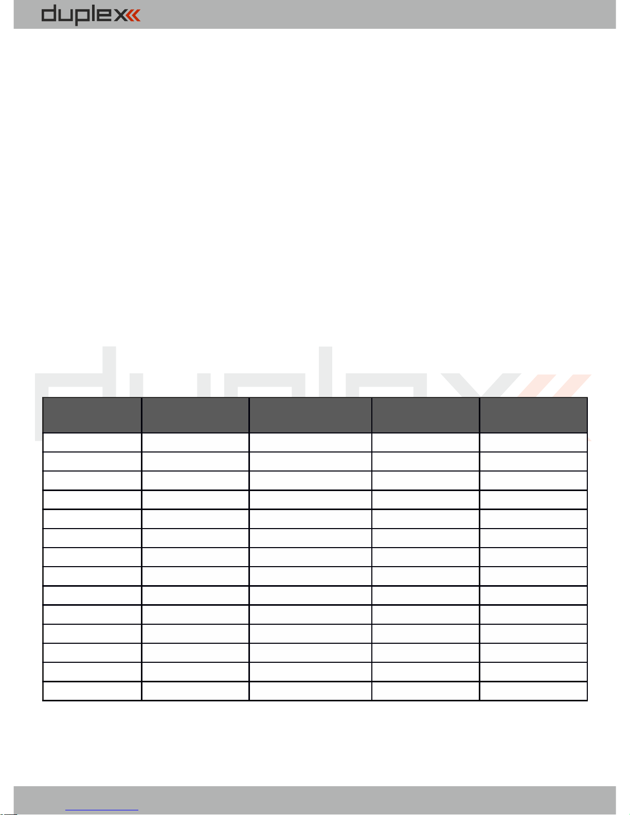
Zuordnungstabelle der Empfängerausgänge:
REX 6
REX 7
REX 10
REX 12
Pin1Y1Y1
Y1
Y1
Pin2Y2Y2
Y2
Y2
Pin3
Y3
Y3
Y3
Y3
Pin4Y4Y4
Y4
Y4
Pin5
Y5/E1
Y5
Y5
Y5
Pin6
Y6/E2
Y6/E1
Y6
Y6
Pin7
Ext.
Y7/E2
Y7
Y7
Pin8
Ext.
Y8/E2
Y8/E2
Pin9Y9 Y9
Pin10
Y10
Y10
Pin11
Bat.
Y11
Pin12
Bat.
Y12
Pin13
E1
E1
Pin14
Ext.
Ext.
Typen von Ausgängen: Y - servo output, dig. out, dig. input
E1,2 - JETIBOX-EX, PPM out, PPM input, EX-Bus, UDI
Ext. - JETIBOX-EX
45
Page 48
computer radio control system
6.5 Auto Set
Aktiviert eine vorgegebene Standardkonfigurationen des
Empfängers
Factory default - setzt den Empfänger auf Werkseinstellungen
zurück
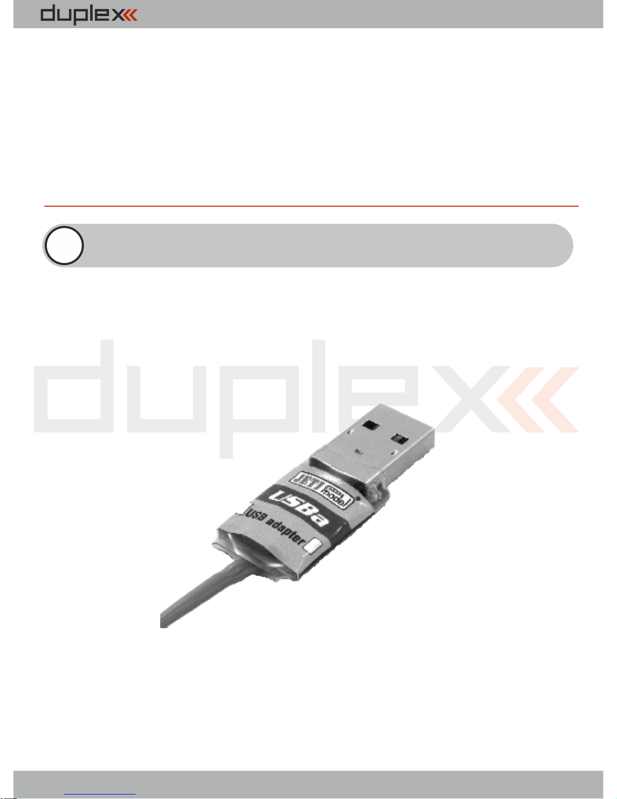
Die Duplex REX Empfänger können über den PC unter
Verwendung des JETI USB Adapters aktualisiert werden. Eine
detaillierte Beschreibung des Updateablaufs finden Sie in der
Anleitung des USB Adapters
7 Empfängerupdate
USB adapter
DE
4
6
Page 49
computer radio control system
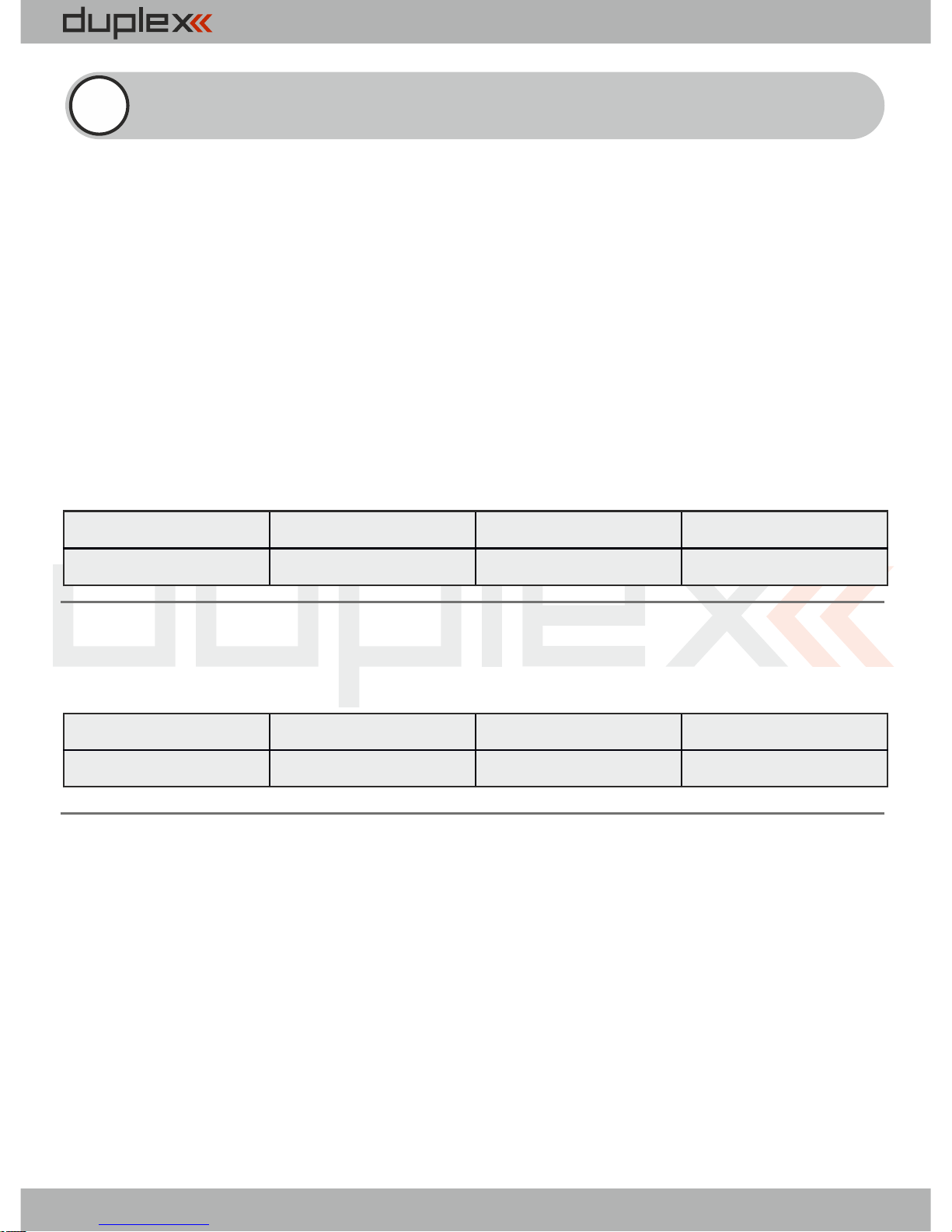
Das klassische Setup für einen Empfänger (für alle
analoge oder digitale Servos)
- Servoimpulse werden im Empfänger generiert
- jedes Servo kann einer bestimmten Gruppe zugeordnet werden
(A bis H)
- Servosignale innerhalb einer Gruppe werden gleichzeitig
generiert
- zwischen zwei aufeinanderfolgenden Servogruppen (A bis H)
ergibt sich eine Verzögerung von 2.5ms.
8 Empfänger-Setup Beispiele
Klassisches Setup für einen Empfänger (für digitale
Servos)
Zweiter Empfänger als Backup (clone Modus)
- Empfänger “liest” die an den “normal Empfänger” gesendeten
Signale mit > nur Empfang
- Betrieb immer nur in Verbindung mit einem normal
gebundenen Empfänger (im Modus Normal)
- sinnvoll z.B. als Backup-Empfänger oder zur Erweiterung der
Kanäle durch zweiten Empfänger
- keine Telemetrieübertragung (auch Anzeige der Signalstärke
nicht verfügbar)
FailSafe
SignalFaultDelay
OutputPeriod
Rx mode
Enabled
1,5s
17ms
Normal
FailSafe
SignalFaultDelay
OutputPeriod
Rx mode
Enabled
1,5s
Auto
Normal
47
Page 50
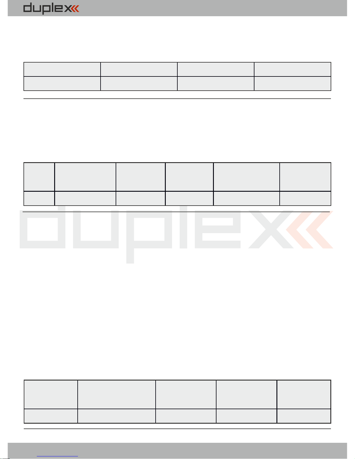
computer radio control system
Empfänger mit Ausgabe des PPM Signals
- PPM positiv oder negativ kann ausgewählt werden
- das PPM Signal kann am Steckplatz E1 oder E2 ausgegeben
werden
- eine beliebige Anzahl von Empfängern im Clone-Modus können
gleichzeitig betrieben werden
FailSafe
SIgnalFaultDelay
OutputPeriod
Rx mode
Disabled
1,5s
17 ms (or Auto)
Clone
FailSafe
OtputPeriod
E1 orE2
Rx mode
OuputChannelCnt
PPM Mode
Enabled
20ms
PPM pos.
Normal
8
Direct
Empfänger mit Ausgabe des PPM Signals als BackupEmpfänger
- das PPM Signal kann am Steckplatz E1 oder E2 ausgegeben
werden
- direkte Ausgabe des PPM Signals ohne Failsafe Einstellungen
oder Hold Funktionen
- jedes empfangene Datenpaket vom Sender wird direkt und
ohne weitere Bearbeitung an den Hauptempfänger
ausgegeben
- wird kein Signal vom Sender empfangen wird auch kein Signal
ausgegeben (Off-Mode)
FailSafe
OuputPeriod
E1 or E2
Rx mode
PPM Mode
Disabled
Auto
PPM pos.
Normal
Direct
48
Page 51
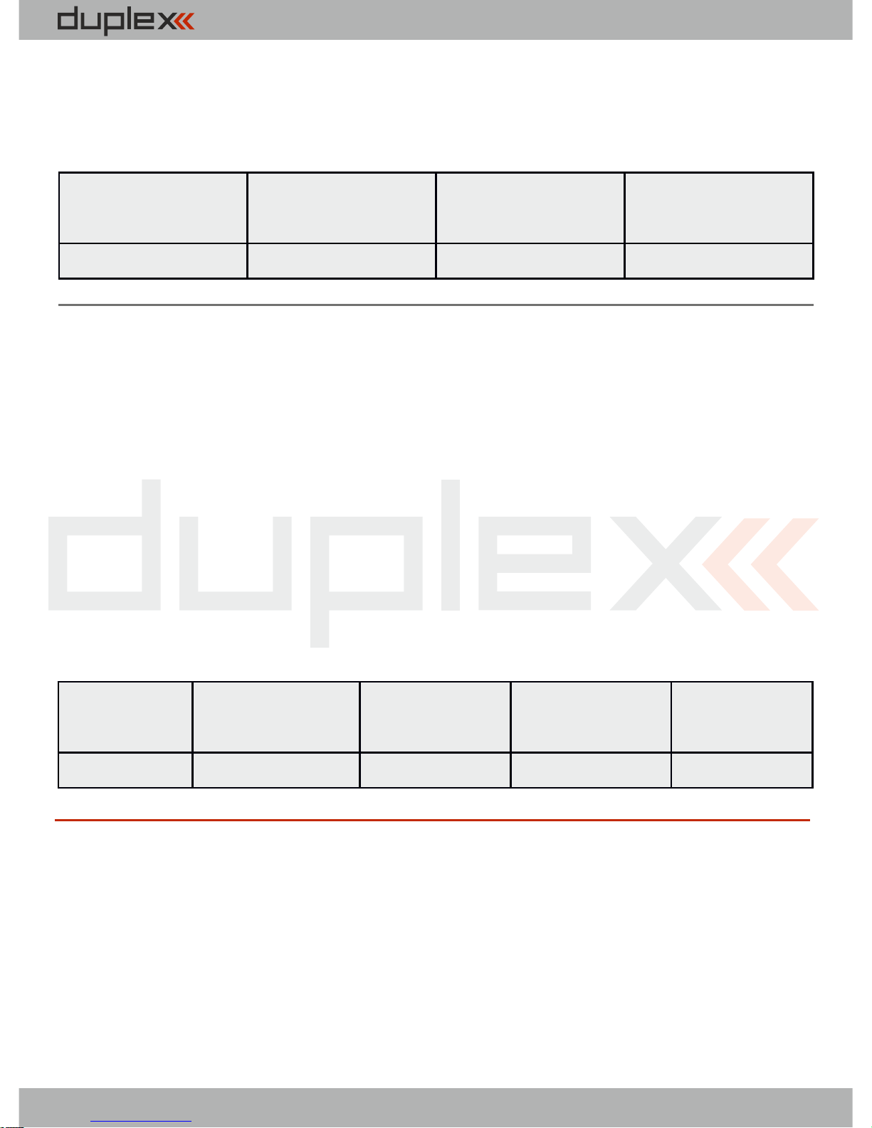
computer radio control system
Empfänger mit EX Bus Verbindung
- z.B. bei der JETI Central Box zum Anschluss der Empfänger
- EX Bus kann am Steckplatz E1 oder E2 ausgegeben werden
FailSafe
OutputPeriod
E1 orE2
Rx mode
Enabled
17 ms (or Auto)
EX Bus
Normal
Empfänger mit Ausgabe des UDI Signals
- für die Ansteuerung verschiedener FBL Systeme oder
Copterflugsteuerungen.
- das UDI Signal kann am Steckplatz E1 oder E2 ausgegeben
werden
- an den Servosteckplätzen wird weiterhin das Servosignal
ausgegeben
- Telemetriesensoren können dann am EXT. Steckplatz
angesteckt werden
FailSafe
OutputPeriod
E1 or E2
Rx mode
UDI Mode
Enabled
17 ms (or Auto)
UDI12
Normal
Direct
49
Page 52
computer radio control system
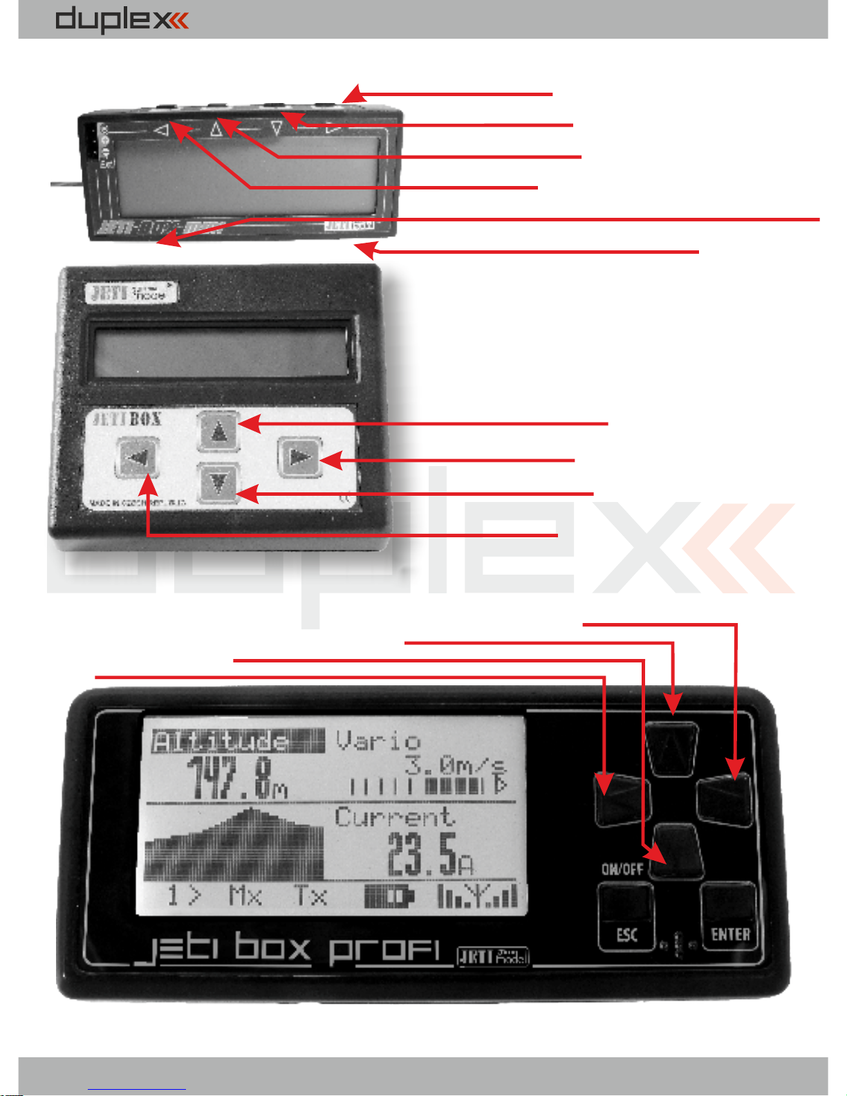
Taste rechts
Taste abwärts
Taste Aufwärts
Taste für den umschaltbaren Eingang
Taste links
Taste Aufwärts U
Taste rechts R
Taste abwärts D
Taste links L
Taste aufwärts
Taste rechts
Taste upwärts
Taste links
JETIBOX mini
JETIBOX
JETIBOX profi
DE
Taste Displaybeleuchtung
50
Page 53

computer radio control system
Wir wünschen Ihnen viel Spaß bei Betreiben unserer Produkte:
JETI model s.r.o. Príbor, www.jetimodel.com
Für unsere Empfänger gewähren wir eine Garantie von 24
Monaten ab dem Tag des Kaufes in der Annahme, dass diese
Empfänger in Übereinstimmung mit der in dieser Anleitung
empfohlenen Spannung betrieben wurden und nicht
mechanisch beschädigt sind.
Garantie und nach Garantie-Service nur durch den Hersteller
und seinen Servicestellen.
EMPFINDLICHE BAUELEMENTE, VOR
ELEKTROSTISCHE AUFLADUNGEN SCHÜTZEN
DE
51
Page 54

computer radio control system
DE
52
Page 55

computer radio control system
JETI model s.r.o.
Lomená 1530, 742 58 Příbor
Czech Republic - EU
www.jetimodel.com
www.jetimodel.de
Duplex-System EX:
• Transmitter modules
• Receivers
• Telemetric sensors
• Compatible accessories
• Display units
Duplex-System EX:
• Sendermodule
• Empfänger
• Telemetrische Sensoren
• Kompatibles Zubehör
• Abbildungseinheiten
 Loading...