


OWNER'S MANUAL
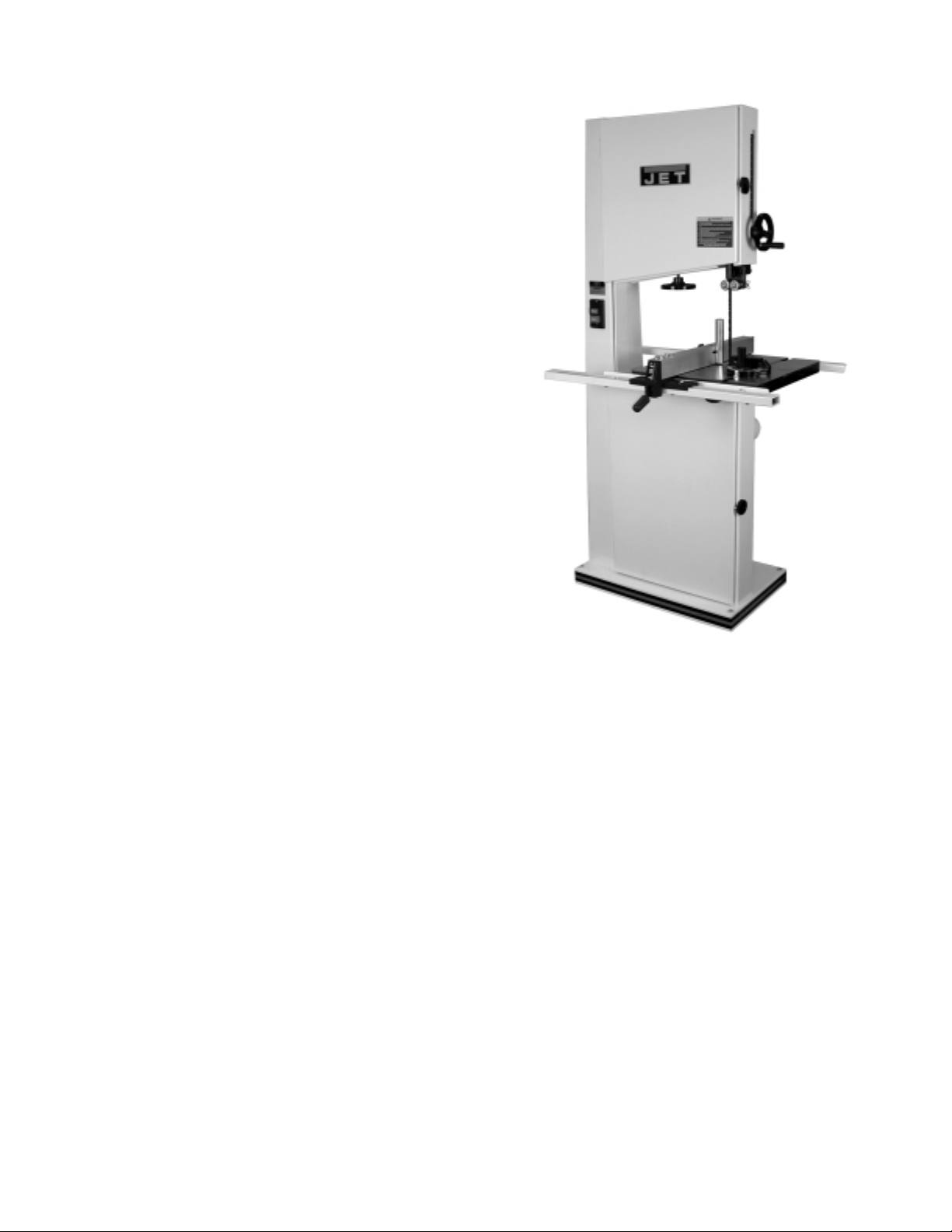
JWBS-18 Woodworking Bandsaw
JET EQUIPMENT & TOOLS, INC. P.O. BOX 1349 Phone: 253-351-6000
A WMH Company Auburn, WA 98071-1349 Fax: 1-800-274-6840
www.jettools.com e-mail jet@jettools.com M-708750B 12/01

This manual has been prepared for the owner and operators of a JET JWBS-18 Woodworking Bandsaw.
Its purpose, aside from machine operation, is to promote safety through the use of accepted correct
operating and maintenance procedures. Completely read the safety and maintenance instructions before
operating or servicing the machine. To obtain maximum life and efficiency from your Bandsaw, and to
aid in using the machine safely, read this manual thoroughly and follow instructions carefully.
Warranty & Service
The JET Group warrants every product it sells. If one of our tools needs service or repair, one of our
Authorized Repair Stations located throughout the United States can give you quick service.
In most cases, any one of these JET Group Repair Stations can authorize warranty repair, assist you in
obtaining parts, or perform routine maintenance and major repair on your JET, Performax or Powermatic
tools.
For the name of an Authorized Repair Station in your area, please call 1-800-274-6848.
More Information
Remember, the JET Group is consistently adding new products to the line. For complete, up-to-date
product information, check with your local JET Group distributor.
JET Group Warranty
The JET Group (including Performax and Powermatic brands) makes every effort to assure that its
products meet high quality and durability standards and warrants to the original retail
consumer/purchaser of our products that each product be free from defects in materials and
workmanship as follow: 1 YEAR LIMITED WARRANTY ON ALL PRODUCTS UNLESS SPECIFIED
OTHERWISE. This Warranty does not apply to defects due directly or indirectly to misuse, abuse,
negligence or accidents, normal wear-and-tear, repair or alterations outside our facilities, or to a lack of
maintenance.
THE JET GROUP LIMITS ALL IMPLIED WARRANTIES TO THE PERIOD SPECIFIED ABOVE, FROM
THE DATE THE PRODUCT WAS PURCHASED AT RETAIL. EXCEPT AS STATED HEREIN, ANY
IMPLIED WARRANTIES OR MERCHANTIBILITY AND FITNESS ARE EXCLUDED. SOME STATES
DO NOT ALLOW LIMITATIONS ON HOW LONG THE IMPLIED WARRANTY LASTS, SO THE ABOVE
LIMITATION MAY NOT APPLY TO YOU. THE JET GROUP SHALL IN NO EVENT BE LIABLE FOR
DEATH, INJURIES TO PERSONS OR PROPERTY, OR FOR INCIDENTAL, CONTINGENT, SPECIAL,
OR CONSEQUENTIAL DAMAGES ARISING FROM THE USE OF OUR PRODUCTS. SOME STATES
DO NOT ALLOW THE EXLUSION OR LIMITATION OF INCIDENTAL OR CONSEQUENTIAL
DAMAGES, SO THE ABOVE LIMITATION OR EXCLUSION MAY NOT APPLY TO YOU.
To take advantage of this warranty, the product or part must be returned for examination, postage
prepaid, to an Authorized Repair Station designated by our office. Proof of purchase date and an
explanation of the complaint must accompany the merchandise. If our inspection discloses a defect, we
will either repair or replace the product, or refund the purchase price if we cannot readily and quickly
provide a repair or replacement, if you are willing to accept a refund. We will return repaired product or
replacement at JET’S expense, but if it is determined there is no defect, or that the defect resulted from
causes not within the scope of JET’S warranty, then the user must bear the cost of storing and returning
the product. This warranty gives you specific legal rights; you may also have other rights which vary
from state to state.
The JET Group sells through distributors only. Members of the JET Group reserve the right to effect at
any time, without prior notice, those alterations to parts, fittings, and accessory equipment which they
may deem necessary for any reason whatsoever.
2

WARNING
1. Read and understand the entire instruction manual before attempting assembly or operation.
2. This bandsaw is designed and intended for use by properly trained and experienced
personnel only. If you are not familiar with the proper and safe operation of a bandsaw, do
not use until proper training and knowledge have been obtained.
3. Always wear approved safety glasses/face shields while using this machine.
4. Make certain the machine is properly grounded.
5. Before operating the machine, remove tie, rings, watches, other jewelry, and roll up sleeves above
the elbow. Remove all loose clothing and confine long hair. Do not wear gloves.
6. Keep the floor around the machine clean and free of scrap material, oil and grease.
7. Keep the machine guards in place at all times when the machine is in use. If removed for
maintenance purposes, use extreme caution and replace the guards immediately.
8. Do not over reach. Maintain a balanced stance at all times so that you do not fall or lean against
blades or other moving parts.
9. Make all machine adjustments or maintenance with the machine unplugged from the power source.
10. Use the right tool. Don’t force a tool or attachment to do a job which it was not designed for.
11. Replace warning labels if they become obscured or removed.
12. Make certain the bandsaw power switch is in the off position before connecting the machine to the
power supply.
13. Give your work undivided attention. Looking around, carrying on a conversation, and “horse-play”
are careless acts that can result in serious injury.
14. Keep visitors a safe distance from the work area.
15. Use recommended accessories; improper accessories may be hazardous.
16. Adjust and position upper and lower blade guides before starting to cut. Upper blade guide should be
adjusted to approximately 1/8” above the material to be cut.
17. Adjust blade tension and tracking before starting to cut.
18. Always keep hands and fingers away from the blade when the machine is running.
19. Stop the machine and wait for the blade to stop moving before removing scrap material from the
table.
20. Use suitable support if stock does not have a flat surface.
21. Hold material firmly against the table.
22. Saw teeth must point down toward the table.
23. Some dust created by power sanding, sawing, grinding, drilling and otherconstruction activities
contains chemicals known to cause cancer, birth defects or other reproductive harm. Some
examples of these chemicals are:
• Lead from lead based paint
• crystallinesilica from bricks and cement andother masonryproducts, and
• arsenic and chromium from chemically-treated lumber.
24. Your risk from those exposures varies, depending on how often you do this type of work. To reduce
your exposure to these chemicals: work in a well ventilated area, and work with approved safety
equipment, such as those dust masks that are specifically designed to filter out microscopic particles.
25. Do not operate tool while under the influence of drugs, alcohol or any medication.
26. Failure to comply with all of these warnings may cause serious injury.
3
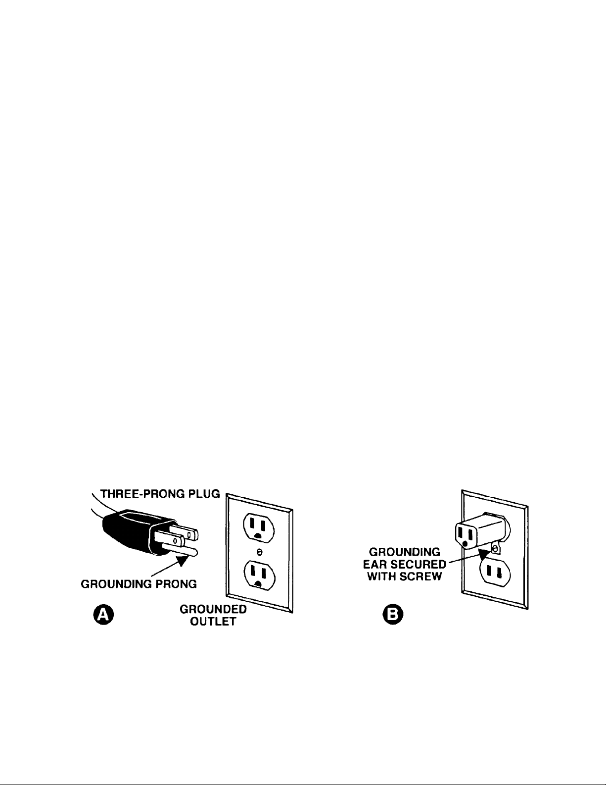
Grounding Instructions
Caution: This tool must be grounded while in use to protect the operator from electric shock.
In the event of a malfunction or breakdown, grounding provides a path of least resistance for electric
current to reduce the risk of electric shock. This tool is equipped with an electric cord having an
equipment-grounding conductor and a grounding plug. The plug must be plugged into a matching outlet
that is properly installed and grounded in accordance with all local codes and ordinances.
Do not modify the plug provided. If it will not fit the outlet, have the proper outlet installed by a qualified
electrician.
Improper connection of the equipment-grounding conductor can result in a risk of electric shock. The
conductor, with insulation having an outer surface that is green with or without yellow stripes, is the
equipment-grounding conductor. If repair or replacement of the electric cord or plug is necessary, do not
connect the equipment-grounding conductor to a live terminal.
Check with a qualified electrician or service personnel if the grounding instructions are not completely
understood, or if in doubt as to whether the tool is properly grounded. Use only three wire extension
cords that have three-prong grounding plugs and three-pole receptacles that accept the tool’s plug.
Repair or replace a damaged or worn cord immediately.
115 Volt Operation
As received from the factory, your bandsaw is ready to run at 115 volt operation. This bandsaw, when
wired for 115 volts, is intended for use on a circuit that has an outlet and a plug that looks the one
illustratedinFigure A. A temporary adapter, which looks like the adapter as illustratedin Figure B, may
be used to connect this plug to a two-pole receptacle, as shown in Figure B if a properly grounded outlet
is not available. The temporary adapter should only be used until a properly grounded outlet can be
installed by a qualified electrician. This adapter is not applicable in Canada. The green colored rigid
ear, lug, or tab, extending from the adapter, must be connected to a permanent ground such as a
properly grounded outlet box, as shown in Figure B.
4
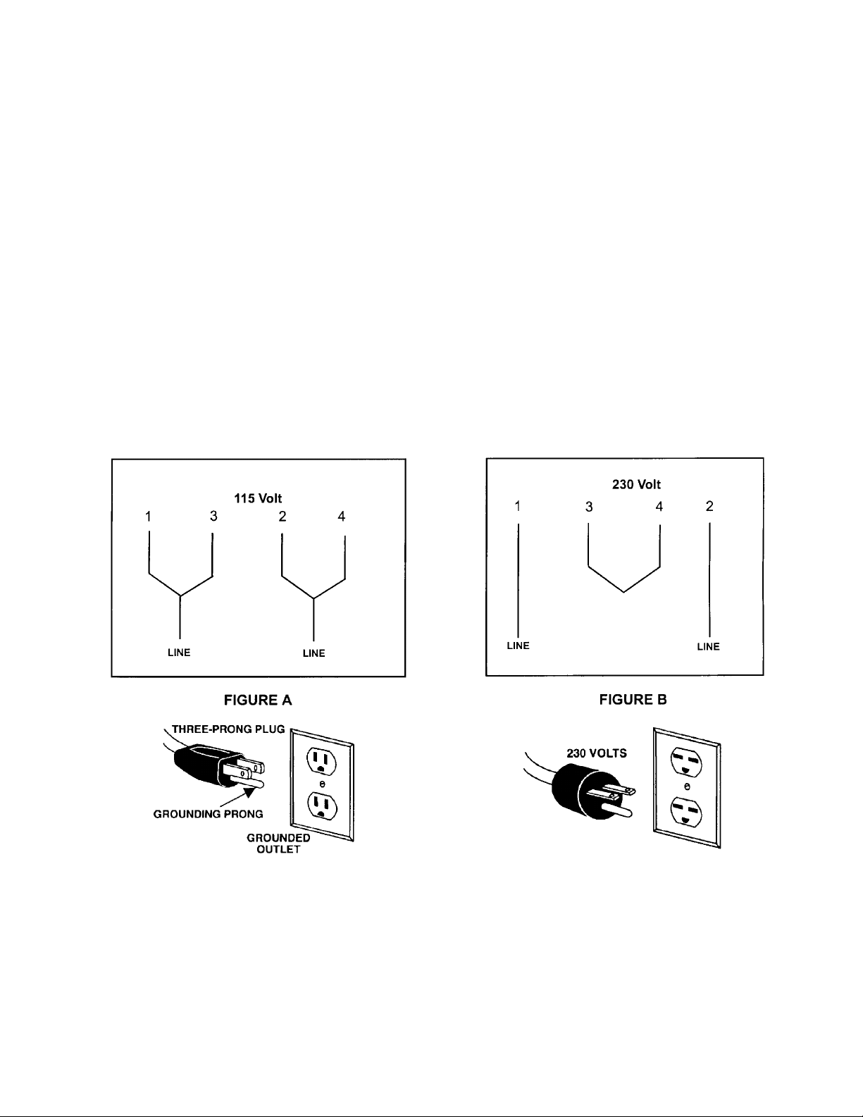
230 Volt Operation
If 230V, single phase operation is desired, the following instructions must be followed:
1. Disconnect the machine from the power source.
2. This bandsaw is supplied with four motor leads that are connected for 115V operation, as shown in
Figure A. Reconnect these four motor leads for 230V operation, as shown in Figure B.
3. The 115V attachment plug supplied with the bandsaw must be replaced with a UL/CSA listed plug
suitable for 230V operation. Contact your local Authorized JET Service Center or qualified electrician
for proper procedures to install the plug. The bandsaw must comply with all local and national codes
after the 230V plug is installed.
4. The bandsaw with a 230V plug should only be connected to an outlet having the same configuration.
No adapter is available or should be used with the 230V plug.
Important: In all cases (115 or 230 volts), make certain the receptacle in question is properly
grounded. If you are not sure, have a registered electrician check the receptacle.
5

Table of Contents
Warranty .................................................................................................................................................2
Warnings ....................................................................................................................... ..........................3
Grounding Instructions.............................................................................................................................4
115 Volt Operation...................................................................................................................................4
230 Volt Operation...................................................................................................................................5
Specifications..........................................................................................................................................6
Contents of Shipping Container ...............................................................................................................7
Unpacking and Setup...............................................................................................................................7
Tools Included for Assembly....................................................................................................................7
Tools Required for Assembly and Adjustments........................................................................................7
Upper Bearing Guide Adjustment.............................................................................................................8
Lower Bearing Guide Adjustment.............................................................................................................9
Mounting the Table..................................................................................................................................9
Adjusting 90 Degree Table Stop............................................................................................................10
Rail Assembly........................................................................................................................................10
Fence Assembly and Adjustment ..................................................................................................... ......11
Resaw Guide.........................................................................................................................................12
Miter Gauge...........................................................................................................................................12
Tilting the Table.....................................................................................................................................12
Height Scale Adjustment .......................................................................................................................12
Changing Blades ...................................................................................................................................13
Adjusting Blade Tension........................................................................................................................14
Adjusting Blade Tracking.......................................................................................................................14
Replacing Belt.......................................................................................................................................15
Adjusting Belt Tension...........................................................................................................................15
Electrical Connections ...........................................................................................................................16
Maintenance..........................................................................................................................................16
Troubleshooting.....................................................................................................................................17
Part’sBreakdowns and Part’sList.....................................................................................................18-26
Wiring Diagram .....................................................................................................................................27
Specifications: JWBS-18
Stock Number..............................................................................................................................708750B
Cutting Capacity (height) ................................................................................................................10-1/4”
Cutting Capacity (width)..................................................................................................................18-3/8”
Maximum Rip Left of Blade w/Fence..............................................................................................16-1/2”
Maximum Rip Right of Blade w/Fence..............................................................................................7-5/8”
Blade Length ...................................................................................................................................... 133”
Blade Speed........................................................................................................................... 3000 SFPM
Minimum Blade Width.........................................................................................................................1/8”
Maximum Blade Width.....................................................................................................................1-1/2”
Table Size...................................................................................................................................19” x 19”
Table Tilt...............................................................................................................................45°Rto10°L
Table Height from Floor ..................................................................................................................37-1/2”
Wheel Diameter .............................................................................................................................18-5/8”
Dust Chute Diameter..............................................................................................................................4”
Overall Dimensions................................................................................................ 71" H x 39" W x 31" D
Motor...................................................................................................................................1-1/2 HP, 1Ph
......................................................................................................................... 115/230V, prewired 115V
Net Weight (approx.) .....................................................................................................................346 lbs.
Shipping Weight (approx.).............................................................................................................407 lbs.
The specifications in this manual are given as general information and are not binding. JET Equipment
and Tools reserves the right to effect, at any time and without prior notice, changes or alterations to
parts, fittings, and accessory equipment deemed necessary for any reason whatsoever.
6
Contents of Shipping Container
1. Bandsaw
1. Table
1. Fence and Rail Assembly
1. Resaw Guide and Knob
1. Miter Gauge
1. Owner’s Manual
1. Warranty Card
1. Accessory Package Contains:
Hardware Bag
2. Knobs
1. Hex Wrench
1. Handle
1. 10/12mm Wrench
Fence Hardware Bag
4. Hex Cap Screws
4. Flat Washers
4. Lock WasherS
Rail Hardware Bag
9. Hex Cap Screws
9. Flat Washers
9. Lock Washers
Unpacking and Setup
1. Remove the crate and packing material
from the bandsaw except for the transport
skid on the bottom.
2. Move the saw to its permanent working
location. The site should be dry, well lit, and
have enough room to handle long stock and
the service and/or adjustment of the
machine from any side.
3. Move the bandsaw off the skid.
4. Clean all rust protected surfaces with a mild
solvent or diesel fuel and a soft cloth. Do
not use lacquer thinner, paint thinner, or
gasoline. These will damage painted
surfaces.
Tools Included for Assembly
1. 10/12mm Open End Wrench
1. Hex Wrench
Tools Required for Assembly &
Adjustments
2. 14mm Open End Wrench
1. Cross Point Screw Driver
1. Combination Square
7
Assembly and Setup
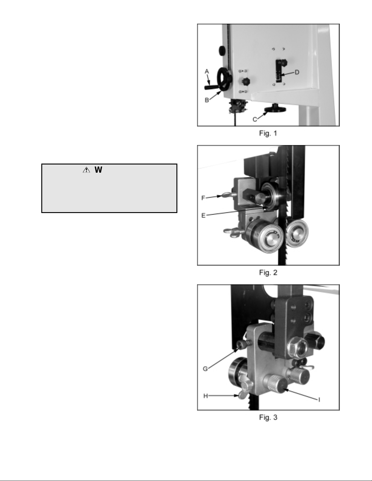
1. Attach the handle (A, Fig. 1) to the
handwheel (B, Fig. 1).
2. Turn blade tension hand wheel (C, Fig. 1)
counter-clockwise to tension blade and
clockwise to loosen the tension. A gauge on
the upper wheel slide bracket (D, Fig. 1)
indicates the approximate tension according
to the width of the blade. The JWBS-18
comes with a 3/4” blade so the tension
should be set at 3/4”.
Note: It is easier to adjust the bearing guides
before mounting the table.
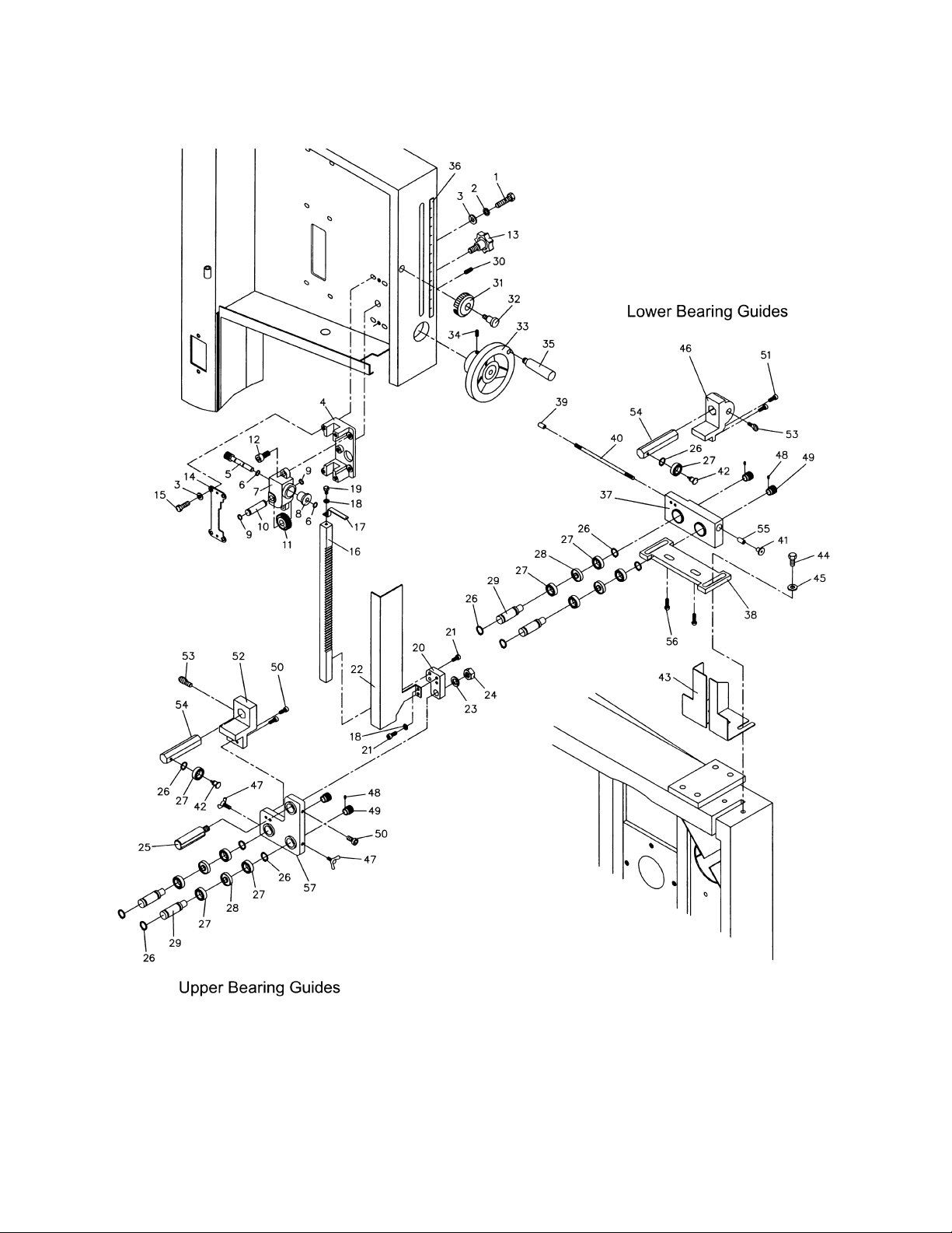
Upper Bearing Guide Adjustment
WARNING
Disconnect machine from the power source,
unplug before making any adjustments!
Blade teeth are sharp! Use care when
working near the saw blade.
Failure to comply may cause serious injury!
1. Blade tension must be properly adjusted
prior to bearing guide setup, see “Adjusting
Blade Tension” page 14.
2. Adjust the back-up bearing (E, Fig. 2) so
that it is 0.003” away from the back of the
blade, about the thickness of a piece of
paper. To make this adjustment loosen
thumb screw (F, Fig. 2) and slide the
bearing and bearing post into position.
Tighten thumb screw.
3. Loosen the socket head cap screw (G, Fig.
3) and slide the bearing assembly until the
bearing guides rest just behind the gullet of
the blade teeth. You may need to readjust
the back-up bearing.
4. Loosen the wing nut (H, Fig. 3) and turn the
adjusting screw (I, Fig. 3) clockwise or
counter-clockwise until the bearing is 0.003”
away from the side of the blade, about the
thickness of a piece of paper. Tighten wing
nut.
5. Adjust the opposite side bearing.
6. Check to make sure the adjustments have
not changed and the bearing guides do not
pinch the blade.
8
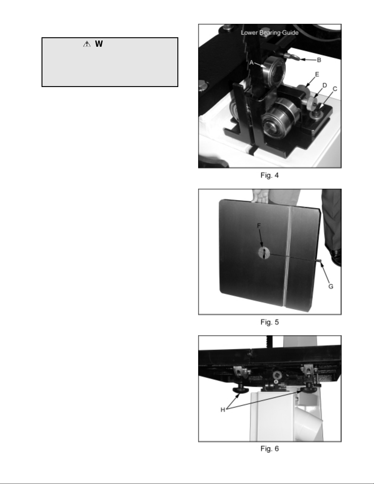
Lower Bearing Guide Adjustment
WARNING
Disconnect machine from the power source,
unplug before making any adjustments!
Blade teeth are sharp! Use care when
working near the saw blade.
Failure to comply may cause serious injury!
1. Blade tension must be properly adjusted
prior to bearing guide setup, see “Adjusting
Blade Tension” page 14.
2. Adjust the back-up bearing (A, Fig. 4) so
that it is 0.003” away from the back of the
blade, about the thickness of a piece of
paper. To make this adjustment loosen
thumb screw (B, Fig. 4) and slide the
bearing, and bearing post into position.
Tighten thumb screw.
3. Loosen the two socket head cap screws (C,
Fig. 4) and slide the bearing assembly until
the bearing guides rest just behind the gullet
of the blade teeth. You may need to
readjust the back-up bearing. Tighten
socket head cap screws.
4. Loosen the thumb screw (D, Fig. 4) and turn
adjusting screw (E, Fig. 4) clockwise or
counter-clockwise until the bearing is 0.003”
away from the side of the blade, about the
thickness of a piece of paper.
5. Adjust the opposite side bearing.
6. Tighten thumb screw (D, Fig. 4). Check to
make sure the adjustments have not
changed and the bearing guides do not
pinch the blade.
Mounting the Table
1. With help from another person mount the
table. Remove the table insert (F, Fig. 5)
and table pin (G, Fig. 5).
2. Slide saw blade through slot in table where
the table pin was located. Rotate the table
90 degrees so that the miter slot is parallel
to the blade, and to the right of the blade
when facing the bandsaw.
3. Line up the trunnions so that the bolts feed
through the trunnion support bracket.
Secure the table with two lock knobs (H, Fig.
6). Reinstall the table insert and table pin.
9

Adjusting90DegreeTableStop
1. Blade tension must be properly adjusted
prior to adjusting 90 degree stop, see
“Adjusting Blade Tension” page 14.
2. Loosen lock knobs (A, Fig. 7) and tilt table
until it rests against table stop bolt (B, Fig.
7). Tighten knobs.
3. Use a square (E, Fig. 8) placed on the table
and against the blade to see if the table is
90 degrees to the blade.
4. If an adjustment is necessary, loosen the
lock knobs. Tilt the table until it is square to
the blade, and tighten the lock knobs.
5. Loosen lock nut (C, Fig. 7) and turn table
stop bolt (B, Fig. 7) until it contacts the
table. Tighten the nut (C, Fig. 7) to hold
table stop in place. When tightening the nut
hold the table stop bolt in place with a
wrench to prevent movement.
6. If necessary, adjust pointer (D, Fig. 7) to
zero.
Rail Assembly
1. Attach the front rail (F, Fig. 9) to the cast
iron table with two 1/4” x 5/8” hex cap bolts,
two 1/4” lock washers, and two 1/4” flat
washers. Bolts should be in approximately
the center of the slot. Hand tighten only at
this time.
2. Attach the rear rail (G, Fig. 9) to the table
with two 1/4” x 5/8” hex cap bolts, two 1/4”
lock washers, and two 1/4” flat washers.
Bolts should be in approximately the center
of the slot. Hand tighten only at this time.
3. Push the front, and rear rails up as far as
they will go.
4. Tighten the four hex cap bolts holding the
front, and rear rails to the table. Do not
over tighten the bolts.
5. Attach the guide tube (H, Fig. 9) to the front
rail with five 1/4” x 5/8” hex cap bolts, five
1/4” lock washers, and five 1/4” flat washers.
Bolts should be in approximately the center
of the slot.
10

Fence Assembly and Adjustment
1. Attach the fence (A, Fig. 10) to the fence
body (B, Fig. 10) with four 5/16” x 3/4” hex
cap bolts, four 5/16” lock washers, and four
5/16” flat washers.
2. Thread a hex nut (D, Fig. 11) onto the pad’s
threaded stud (E, Fig. 11) and insert through
the fence and rear hook (F, Fig. 11).
Secure in place using a hex nut, lock washer
and flat washer (G, Fig. 11).
Note: The hook should be adjusted so that it
overlaps the rear rail by approximately 1/8”.
3. Place fence assembly onto the guide tube.
The rear hook should engage the rear rail.
4. Check the clearance between the table and
the fence. The gap should be the same at
the front of the table as it is at the rear. If
the gap width is different, adjust the foot at
the rear of the fence until the gap width is
the same, Figure 12.
Note: You can also adjust the front rail, or rear
rail up, or down to achieve the proper clearance.
5. With a square verify the fence face is
perpendicular to the table top. If it is not the
front rail will need to be adjusted parallel to
the table top. This can be accomplished by
measuring from the top of the table to the
top of the front rail. The measurement
should be the same at both ends of the
table.
6. Move the fence assembly so that it aligns
parallel to the blade, and lock the fence by
pushing the lock handle down, Figure 10.
7. Loosen the four hex cap bolts that hold the
fence, to the fence body, and align the fence
to the blade. Tighten the four hex cap bolts.
8. Check to see that the pointer (C, Fig. 10) is
aligned with the zero marking on the guide
rail. If adjustment is necessary loosen the
screw that holds the pointer in place and line
up to the zero mark. Tighten the screw.
Note: If you cannot get the pointer lined up with
the zero mark you can slide the guide tube and
front rail left, or right to achieve the proper
setting.
11

Resaw Guide
For resawing attach the post (A, Fig. 13) to
fence with the lock knob (B, Fig. 13). There is a
slotted hole in the fence that will accommodate
the resaw kit. Position the post so that it is
centered with the front edge of the blade. The
resaw guide will give you a taller, single point
contact surface during resawing.
Miter Gauge
1. Place the miter gauge in the table slot.
2. With a square verify the miter gauge face is
square to the blade.
3. If the miter gauge is not square to the blade
loosen the lock knob (C, Fig. 13) and adjust
to the proper setting. Tighten the lock knob.
4. If the pointer is not at 90 degrees, loosen
the screw (D, Fig. 13) holding the pointer
and move the pointer to 90 degrees.
Tilting the Table
1. Disconnect the machine from the power
source, unplug.
2. Loosen the lock knobs (E, Fig. 14).
3. Tilt table up to 45 degrees to the right, or up
to 10 degrees to the left.
4. Tighten the lock knobs.
Note: Table stop bolt (F, Fig. 14) must be
removedtotilttabletotheleft.
Height Scale Adjustment
1. Disconnect the machine from the power
source, unplug.
2. The upper bearing guide should be set
about 1/8” above the material to be cut.
3. Measure from the table top to the bottom of
the bearing guides, Figure 15.
4. Set the indicator to this measurement on the
height scale. Grasp the end of the indicator
(G, Fig. 15) between your finger, and thumb.
Move the indicator into position.
12
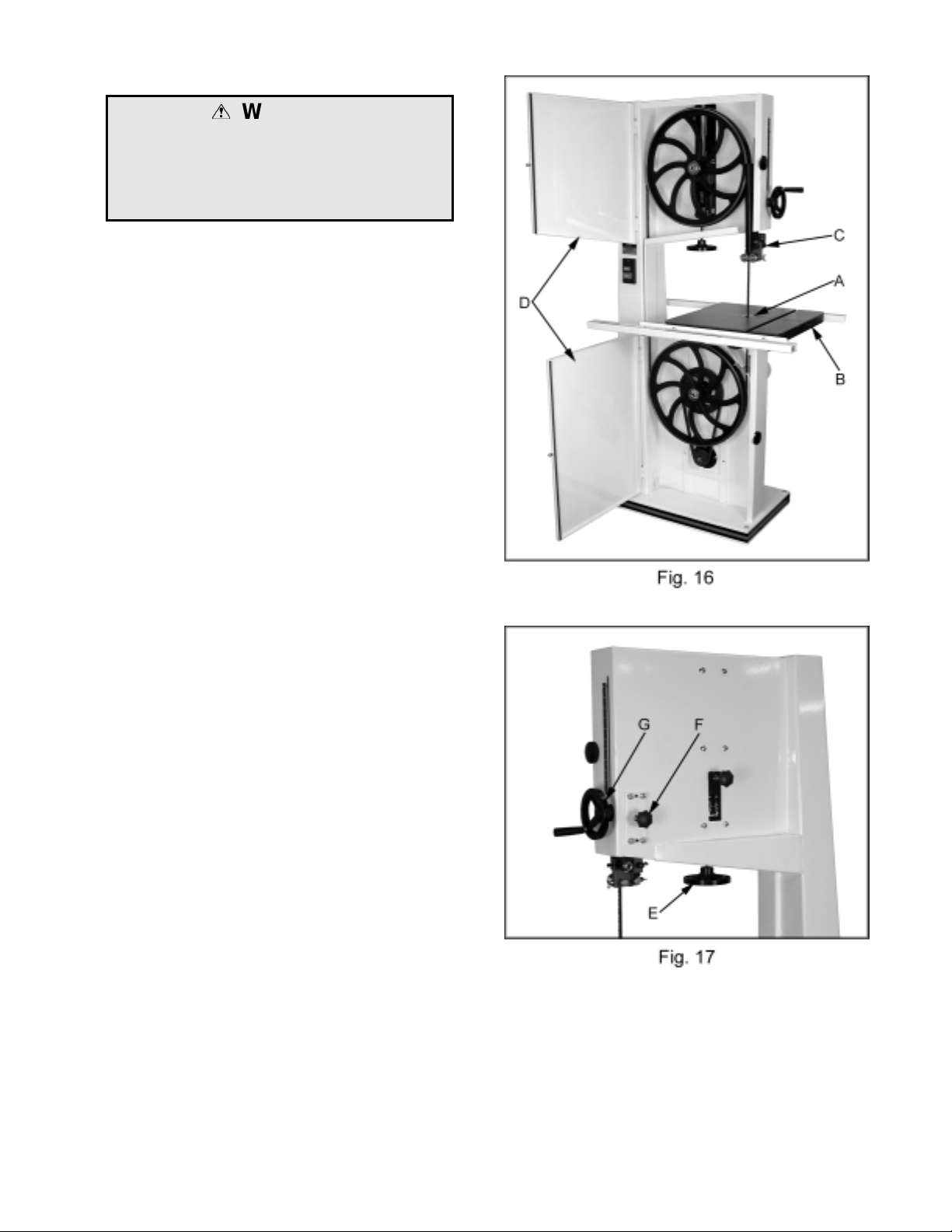
Changing Blades
WARNING
Disconnect machine from the power source,
unplug!
Blade teeth are sharp! Use care when
handling the saw blade.
Failure to comply may cause serious injury!
1. Disconnect the machine from the power
source.
2. Remove the table insert (A, Fig. 16), and
table pin (B, Fig. 16).
3. Lower the upper blade guide assembly
about half way by loosening the lock knob
(F, Fig. 17) and turning the hand wheel (G,
Fig. 17).
4. Loosen socket head cap screw (C, Fig. 16)
and slide the bearing assembly back as far
as it will go.
5. Open both wheel covers (D, Fig. 16).
6. Loosen blade tension by turning blade
tension hand wheel (E, Fig. 17) clockwise
until it stops.
Note: You may want to wear leather work
gloves while removing and handling the blade.
7. Carefully remove blade from upper and
lower wheels. Remove the blade from
between upper, and lower bearing guides.
Turn blade and direct through slot in table.
8. Make sure blade teeth point down toward
table and guide the new blade through table
slot. Place blade in upper, and lower
bearing guides.
9. Place blade in the middle of the upper and
lower wheels.
10. Tension and track blade before operating
saw. Find instructions for tensioning and
tracking the blade on the next page under
"Adjusting Blade Tension" and "Adjusting
Blade Tracking".
11. Replace table insert and table pin.
13

Adjusting Blade Tension
1. Disconnect machine from the power
source, unplug.
2. Turn blade tension hand wheel (A, Fig. 18)
counter-clockwise to tension blade, and
clockwise to loosen the tension. A gauge on
the upper wheel slide bracket (B, Fig. 18)
indicates the approximate tension according
to the width of the blade. The JWBS-18
comes with a 3/4” blade so the tension
should be set at 3/4” when using this blade.
• As you become familiar with the saw, you
may find it necessary to change the blade
tension from the initial setting. Changes in
blade width, and the type of material being
cut will have an effect on blade tension.
• Keep in mind that too little, or too much
blade tension can cause blade breakage
and/or poor cutting performance.
5. Continue with adjustments until the blade is
tracking properly.
6. Tighten the wing nut (C, Fig. 18).
Adjusting Blade Tracking
WARNING
Disconnect machine from the power source!
Never adjust blade tracking with the
machine running!
Failure to comply may cause serious injury!
Note: Blade tracking has been adjusted at the
factory. If, how ever, it is determined that blade
tracking needs adjustment:
1. Blade must be properly tensioned before
adjusting blade tracking. Make sure upper
and, lower bearing guides do not interfere
with the blade while adjusting the tracking.
2. Open the upper wheel door. Rotate the
wheel forward, and observe the position of
the blade on the wheel. The blade should
rest in approximately the center of the
wheel.
3. If adjustment is necessary, loosen the wing
nut (C, Fig. 18) at the top rear of the saw.
4. Adjust tracking by turning the knob (D, Fig.
18) in 1/4 turn increments. Rotate the wheel
forward, and observe the position of the
blade on the wheel. Rotating knob (D, Fig.
18) counter-clockwise should move the
blade towards the front of the wheel.
Rotating the knob clockwise should move
the blade towards the back of the wheel.
14

Replacing V-Belt
1. Disconnect the machine from the power
source.
2. Release blade tension by turning blade
tension hand wheel clockwise.
3. Release belt tension by loosening the two
hex cap bolts (A, Fig. 19 the pivot bolt is not
shown in the photo). Raise the motor and
place a block of wood under the motor to
take the tension off the belt.
4. Open the lower wheel door and remove hex
nut, and washer (B, Fig. 20).
5. Remove the wheel (C, Fig. 21). If the lower
wheel does not come off easily you may
need to use a pulley puller to remove the
lower wheel.
6. Remove the old belt (D, Fig. 21) and
replace the belt.
7. Reinstall the lower wheel and tighten the
hex nut.
8. Remove the wood block, or support from
below the motor and adjust the belt tension.
See “Adjusting the Belt Tension.”
9. Set the blade tension. See “Adjusting Blade
Tension” on the previous page.
10. Check the blade tracking. See “Adjusting
Blade Tracking” on the previous page.
Adjusting Belt T ension
The belt comes adjusted from the factory. If
adjustment is needed:
1. Disconnect the machine from the power
source.
2. Set the belt tension by lightly pressing down
on the motor and tightening the hex cap
screw (A, Fig. 19 the pivot bolt is not shown
in the photo).
Note: The weight of the motor should put
enough tension on the belt. You just want to
push down lightly to take up any slack.
15

Electrical Connections
WARNING!
All electrical connections must be done by a
qualified electrician!
Failure to comply may result in loss of
property and/or serious injury!
• JWBS-18 is rated at 1-1/2 HP, 1Ph,
115V/230V, prewired 115V.
The bandsaw comes with a 115V plug (A, Fig.
22). If you switch to 230V a plug needs to be
purchased for the bandsaw that matches the
230V outlet you intend to use.
Confirm power at the site is the same as the
saw before making any electrical connections.
Review the wiring diagram on page 27.
Review “Grounding Instructions” on page 4,
“115 Volt Operation” also on page 4 and 230
Volt Operation on page 5.
Maintenance
Keep bearing guides clean and free of build up.
Do not let saw dust build up in the upper and
lower wheel housings. Vacuum out frequently.
Connect the bandsaw to a JET dust collection
system.
Clean and grease the raising/lowering rack for
the upper bearing guides if it becomes difficult
to raise, or lower.
Clean, and oil the tensioning mechanism if it
becomes difficult to adjust.
Vacuum out the motor fan cover.
16

Troubleshooting
Trouble Possible Cause Solution
Saw stops or will not start
Does not make accurate 45°°°° or
90°°°° cuts
Blade wanders during cut
1. Saw unplugged
2. Fuse blown or circuit breaker
tripped
3. Cord damaged
1. Stop not adjusted correctly
2. Angle pointer not set
accurately
3. Miter gauge out of
adjustment
1. Fence not aligned with blade
2. Warped wood
3. Excessive feed rate
4. Incorrect blade for cut
5. Blade tension not set
properly
1. Check plug connections
2. Replace fuse or reset circuit
breaker
3. Replace cord
1. Check blade with square and
adjust stop
2. Check blade with square and
adjust pointer
3. Adjust miter gauge
1. Check and adjust fence
2. Select another piece of wood
3. Reduce feed rate
4. Change blade to correct type
5. Set blade tension according
to blade size
Saw makes unsatisfactory
cuts
Blade does not come up to
speed
Saw vibrates excessively
6. Guide bearings not set
properly
1. Dull blade
2. Blade mounted wrong
3. Gum or pitch on blade
4. Incorrect blade for cut
5. Gum or pitch on table
1. Extension cord too light or to
long
2. Low shop voltage
1. Base on uneven floor
2. Bad V-belt
3. Motor mount is loose
4. Loose hardware
6. Review guide bearing
adjustment on pages 8 & 9
1. Replace blade
2. Teeth should point down
3. Remove blade and clean
4. Change blade to correct type
5. Clean table
1. Replace with adequate size
and length cord
2. Contact your local electric
company
1. Reposition on flat, level
surface
2. Replace V-belt
3. Tighten motor mount
hardware
4. Tighten hardware
17

Upper Wheel Assembly
18

Upper Wheel Assembly
Index Part
No. No. Description Size Qty.
1.......... JWBS18-101W................ White Saw Body............................................ ...................................1
2.......... TS-0152011 ..................... Carriage Bolt................................................. 5/16-18 x 1”................6
3.......... JWBS18-103....................Upper Wheel Bracket .................................... ...................................2
4.......... TS-0680031 ..................... Flat Washer................................................... 5/16 ............................6
5.......... TS-0720081 ..................... Lock Washer................................................. 5/16............................6
6.......... TS-0561021 ..................... Hex Nut......................................................... 5/16-18.......................6
7.......... 994542............................. Switch........................................................... ...................................1
8.......... JWBS18-108....................Hex Cap Bolt................................................. M8 x 65 ......................1
9.......... TS-0680021 ..................... Flat W asher................................................... 1/4..............................4
10........JWBS18-110.................... Sliding Bracket.............................................. ........................... ........1
11........JWBS18-111.................... BladeTension Indicator................................. ...................................1
12........JWBS18-112.................... Adjustment Bracket....................................... ...................................1
13........JWBS18-113.................... Shaft Bracket................................................. ................................... 1
14........TS-1540061..................... Hex Nut......................................................... M8..............................1
15........JWBS18-115.................... Spring............................................................ ...................................1
16........JWBS18-116.................... Square Nut.................................................... ...................................1
17........JWBS18-117.................... Pointer........................................................... ...................................1
18........JWBS18-118.................... Screw............................................................ M5 x 8 ........................1
19........JWBS18-119.................... Set Block....................................................... ...................................1
20........TS-0267021..................... Set Screw...................................................... 1/4-20 x 1/4 ................1
21........JWBS18-121.................... Bracket.......................................................... ...................................1
22........TS-0050021..................... Hex Cap Bolt................................................. 1/4-20 x 5/8 ................ 4
23........JWBS18-123.................... BladeAdjusting Screw................................... ...................................1
24........JWBS18-124.................... E-Ring........................................................... E-9.............................1
25........JWBS18-125.................... Hand W heel .................................................. ...................................1
26........TS-0267041..................... Socket Set Screw.......................................... 1/4-20x 3/8 ................2
27........TS-0209021..................... Socket Head Cap Screw................................ 3/8-16 x 5/8................1
28........TS-0720091..................... Lock W asher................................................. 3/8..............................1
29........JWBS18-129.................... Upper Wheel Shaft........................................ ...................................1
30........BB-6203ZZ ...................... Ball Bearing................................................... 6203...........................2
31........JWBS18-131.................... Retaining Ring............................................... R40............................2
32........JWBS18-132.................... Upper Wheel ................................................. ...................................1
33........JWBS18-133.................... Tire................................................................ ...................................1
34........JWBS18-134.................... Flat Washer................................................... ...................................1
35........JWBS18-135.................... Hex Nut......................................................... 5/8-18UNF L.H...........1
36........709405............................. Replacement Blade 1-1/4" x 0.035" x 1.3 Hook x 133".........................
............ 709404..............................Replacement Blade 1" x 0.035" x 2 Hook x 133" .................................
............ 709402..............................Replacement Blade 1/2" x 0.025" x 3 Hook x 133"...............................
............ 709400..............................Replacement Blade 1/4 x 0.025" x 6 Skip x 133”.................................
............ 709403............................. Replacement Blade 3/4" x 0.032 x 3 Hook x 133"................................
............ 709401..............................Replacement Blade 3/8" x 0.025" x 4 Skip x 133"................................
37........TS-0590061..................... Wing Nut....................................................... 5/16............................1
38........JWBS18-138.................... Lock Knob..................................................... 5/16............................1
39........JWBS18-139W ................ White Upper Front Door ................................ ...................................1
40........JWBS18-140.................... JET Plaque.................................................... ...................................1
41........JWBS18-141.................... Warning Label............................................... ...................................1
42........JWBS18-142.................... Bolt................................................................ ...................................1
43........TS-0561011..................... Hex Nut......................................................... 1/4-20 .........................1
44........JWBS18-144.................... Screw............................................................ 3/16 x 3/4 ...................2
45........JWBS18-39A................... Door Hinge Pin.............................................. ...................................2
19

Lower Wheel and Motor Assembly
20

Lower Wheel and Motor Assembly
Index Part
No. No. Description Size Qty.
1.......... JWBS18-201N................. BearingBase................................................. ...................................1
2.......... JWBS20-62......................Adjusting Bolt................................................ ...................................4
3.......... TS-0720091 ..................... Lock Washer................................................. 3/8..............................4
4.......... TS-0060081 ..................... Hex Cap Bolt................................................. 3/8 x 1-3/4..................4
5.......... BB-6204ZZ ...................... Ball Bearing................................................... 6204...........................1
6.......... JWBS18-206N................. Spindle.......................................................... ...................................1
7.......... JWBS18-207....................Key................................................................ 7 x 7 x 40 ...................1
8..........JWBS18-208N................. Spindle Pulley ............................................... ...................................1
9.......... VB-B42 ............................ V-Belt............................................................ B-42...........................1
10........JWBS18-210.................... Lower Wheel ................................................. ...................................1
11........JWBS18-133.................... Tire................................................................ ...................................1
12........TS-0680081..................... Flat Washer...................................................5/8..............................1
13........JWBS18-135.................... Hex Nut......................................................... 5/8-18UNF L.H...........1
14........JWBS18-214.................... Hex Nut......................................................... 5/8-18UNF R.H...........1
15........JWBS18-215.................... Bearing Cover............................................... ...................................1
16........JWBS18-216.................... Lock Washer................................................. 3/16............................3
17........JWBS18-217.................... Screw............................................................ 3/16 x 3/8 ...................3
18........JWBS18-218.................... Motor............................................................. ...................................1
............ JWBS18-CAP.................. Capacitor (not shown)........................ ...............................................1
............ JWBS18-CAP1................ Capacitor Cover (not shown)............. ...............................................1
............ JWBS18-FAN.................. Fan (not shown)................................. ...............................................1
............ JWBS18-CS.....................Centrifugal Switch (not shown).......... ...............................................1
............ JWBS18-MFC.................. Motor Fan Cover (not shown)........................ ...................................1
19........JWBS18-219.................... Motor Bracket................................................ ...................................1
20........TS-0081031..................... Hex Cap Bolt................................................. 5/16 x 3/4 ..................4
21........TS-0680031..................... Flat Washer...................................................5/16............................4
22........TS-0060051..................... Hex Cap Bolt................................................. 3/8-16 x 1 ...................2
23........TS-0720091..................... Lock W asher................................................. 3/8..............................2
24........TS-0680041..................... Flat Washer...................................................3/8..............................2
25........JWBS18-225.................... Motor Pulley.................................................. ...................................1
26........TS-0267021..................... Socket Set Screw.......................................... 1/4-20x 3/8 ................2
27........JWBS18-227W ................ Lower Front Door........................................... ...................................1
28........JWBS18-142.................... Bolt................................................................ ...................................1
29........TS-0561011..................... Hex Nut......................................................... 1/4-20 .........................1
30........JWBS20-2 ....................... Lock Knob..................................................... ...................................1
31........JWBS20-3 ....................... Screw............................................................ 1/4 x 3/4.....................1
32........JWBS20-8W.................... White Dust Chute.......................................... ...................................1
33........TS-0680031..................... Flat Washer...................................................5/16............................2
34........TS-0051051..................... Hex Cap Bolt................................................. 5/16-18 x 1 ................. 2
35........JWBS18-235.................... Plate.............................................................. ...................................1
36........JWBS18-236.................... Screw............................................................ 3/16 x 1/2 ...................2
37........JWBS18-237.................... Strain Relief Bushing..................................... ...................................2
38........JWBS18-238.................... Screw............................................................ 3/16 x 1-1/2................2
39........TS-0680011..................... Flat Washer...................................................3/16............................2
40........JWBS18-240.................... Brush............................................................. ...................................1
41........JWBS18-241.................... Lock Washer................................................. 3/16............................2
42........JWBS18-242.................... Hex Nut......................................................... 3/16............................2
43........JWBS18-243.................... Motor Cord.................................................... ...................................1
44........JWBS18-244.................... Power Cord................................................... ...................................1
45........BB-6205ZZ ...................... Ball Bearing................................................... 6205...........................1
46........JWBS18-246.................... I.D. Label....................................................... ...................................1
47........JWBS18-247.................... Motor Label ................................................... ...................................1
48........JWBS18-39A................... Door Hinge Pin.............................................. ...................................2
21
Blade Guides Assembly
22

Blade Guides Assembly
Index Part
No. No. Description Size Qty.
1.......... TS-0051051 ..................... Hex Cap Bolt................................................. 5/16-18 x 1.................4
2.......... TS-0720081 ..................... Lock Washer................................................. 5/16............................4
3.......... TS-0680031 ..................... Flat Washer................................................... 5/16 ............................8
4.......... JWBS18-304....................Guide Bar Bracket......................................... ...................................1
5.......... JWBS18-305....................Worm............................................................ ...................................1
6.......... JWBS18-306....................E-Ring........................................................... E-8.............................2
7.......... JWBS18-307....................Gear Base..................................................... ...................................1
8.......... JWBS18-308....................Bushing......................................................... ...................................1
9.......... JWBS18-309....................C-Ring........................................................... S-12 ...........................2
10........JWBS18-310.................... Shaft ............................................................. ...................................1
11........JWBS18-311.................... Gear.............................................................. ...................................1
12........TS-0208071..................... Hex Socket Cap Screw.................................. 5/16-18 x 1-1/4 ...........2
13........JWBS18-313.................... Lock Knob..................................................... 5/16............................1
14........JWBS18-314.................... Plate.............................................................. ...................................1
15........TS-0051011..................... Hex Cap Bolt................................................. 5/16-18 x 1/2 ..............4
16........JWBS18-316.................... Guide Bar...................................................... ...................................1
17........JWBS18-317.................... Pointer........................................................... ...................................1
18........TS-0720071..................... Lock W asher................................................. 1/4..............................3
19........TS-0050011..................... Hex Cap Bolt................................................. 1/4-20 x 1/2 ................ 1
20........JWBS18-320N................. Guide Bracket............................................... ...................................1
21........TS-0207021..................... Hex Socket Cap Screw.................................. 1/4-20 x 1/2................4
22........JWBS18-322.................... BladeGuard.................................................. ...................................1
23........TS-0720111..................... Lock W asher................................................. 1/2..............................1
24........TS-0561051..................... Hex Nut......................................................... 1/2-13 .........................1
25........JWBS20-110.................... Locking Shaft ................................................ ...................................1
26........JWBS20-326.................... C-Ring........................................................... .................................10
27........BB-6202ZZ ...................... Ball Bearing................................................... 6202.........................10
28........JWBS20-328.................... Spacer........................................................... ...................................4
29........JWBS20-329.................... Shaft ............................................................. ...................................2
30........TS-0270031..................... Set Screw...................................................... 5/16-18 x 3/8 ..............2
31........JWBS20-2 ....................... Lock Knob..................................................... ...................................1
32........JWBS20-3 ....................... Screw............................................................ 1/4 x 3/4.....................1
33........JWBS18-333.................... Hand W heel .................................................. ...................................1
34........TS-0267041..................... Set Screw...................................................... 1/4-20 x 3/8 ................1
35........JWBS20-103A................. Handle........................................................... ...................................1
36........JWBS18-336.................... Cutting Height Scale...................................... ...................................1
37........JWBS20-337.................... Bracket.......................................................... ...................................1
38........JWBS20-338.................... Base.............................................................. ...................................1
39........JWBS20-339.................... Threaded Lock Bushing................................. ...................................1
40........JWBS20-340.................... Bolt................................................................ ...................................1
41........JWBS20-341.................... Lock Knob..................................................... ...................................1
42........JWBS20-342.................... Screw............................................................ ...................................2
43........JWBS18-343.................... Lower Blade Guard........................................ ...................................1
44........TS-0050021..................... Hex Cap Screw .............................................1/4-20 x 5/8 ................ 2
45........TS-0680021..................... Flat Washer...................................................1/4..............................2
46........JWBS20-360.................... Bracket.......................................................... ...................................1
47........JWBS20-324.................... Wing Bolt ...................................................... ...................................2
48........JWBS20-348.................... Set Screw......................................................M4 x 4........................8
49........JWBS20-349.................... Thumb Screw................................................ ...................................4
50........TS-0207031..................... Hex Socket Cap Screw.................................. 1/4-20 x 5/8................3
51........TS-0207021..................... Hex Socket Cap Screw.................................. 1/4-20 x 1/2................2
52........JWBS20-352.................... Bracket.......................................................... ...................................1
53........JWBS20-353.................... Thumb Screw................................................ 1/4 x 1/2.....................2
23

Index Part
No. No. Description Size Qty.
54........JWBS20-354.................... Bearing Support ............................................ ...................................2
55........JWBS20-355.................... Lock Bushing................................................. ...................................1
56........JWBS20-357.................... Hex Socket CapScrew.................................. 3/16 x 3/8 ...................2
57........JWBS20-358.................... Bearing Bracket............................................. ...................................1
24

Table and Fence Assembly
25

Table and Fence Assembly
Index Part
No. No. Description Size Qty.
1.......... JWBS18-401....................Lock Knob..................................................... ...................................1
2.......... TS-0680021 ..................... Flat Washer................................................... 1/4............................11
3.......... JWBS18-403....................Miter Gauge Body ......................................... ...................................1
4.......... 200156............................. Guide Disc..................................................... ................................... 1
5.......... JWBS18-405....................Pan Head Screw............................................M6 x 8........................1
6.......... JWBS18-406....................Pointer........................................................... ...................................1
7.......... JWBS18-407....................Guide Bar...................................................... ........................ ...........1
8.......... JWBS18-408N................. Trunnion Support Bracket.............................. ...................................1
9.......... TS-0051071 ..................... Hex Cap Bolt................................................. 5/16-18 x 1-1/2...........4
10........TS-0720081..................... Lock W asher................................................. 5/16 ............................8
11........TS-0270061..................... Set Screw...................................................... 5/16-18 x 5/8 ..............2
12........TS-0060111..................... Hex Cap Bolt................................................. 3/8-16 x 2-1/2.............1
13........TS-0561031..................... Hex Nut......................................................... 3/8-16 .........................1
14........TS-0720091..................... Lock W asher................................................. 3/8..............................1
15........JWBS18-415.................... Lock Knob..................................................... ...................................2
16........JWBS18-416.................... Trunnion........................................................ ...................................2
17........JWBS18-417.................... Trunnion Clamp Shoe.................................... ...................................2
18........TS-1491081..................... Hex Cap Bolt................................................. M10 x 50....................2
19........TS-1482021..................... Hex Cap Screw .............................................M6 x 12......................6
20........JWBS18-420.................... Scale............................................................. ...................................1
21........JWBS18-421.................... Table............................................................. ...................................1
22........JWBS18-422W ................ Front Rail ...................................................... ...................................1
23........TS-0050021..................... Hex Cap Bolt................................................. 1/4-20 x 5/8 ................ 9
24........TS-0720071..................... Lock W asher................................................. 1/4............................10
25........JWBS18-425.................... Scale............................................................. ...................................1
26........JWBS18-426W ................ Guide Rail..................................................... ...................................1
27........JWBS18-427W ................ Rear Rail....................................................... ...................................1
28........JWBS20-144.................... Table Insert................................................... ...................................1
29........JWBS20-145.................... Roll Pin .........................................................3 x 10.........................1
30........JWBS18-430.................... Fence Body................................................... ...................................1
31........JWBS18-431.................... Knob.............................................................. ...................................1
32........JWBS18-432.................... Lock Handle .................................................. ...................................1
33........JWBS18-433W ................ Lock Plate..................................................... ...................................1
34........JWBS18-434.................... Pad............................................................... ...................................5
35........JWBS18-435.................... Pin................................................................. ...................................1
36........JWBS18-436.................... Pin................................................................. ...................................1
37........JWBS18-437.................... Fence............................................................ ...................................1
38........TS-0081031..................... Hex Cap Bolt................................................. 5/16 x 3/4 ...................4
39........TS-0680031..................... Flat Washer...................................................5/16............................4
40........JWBS18-440.................... Screw............................................................ 3/16 x 1/4 ...................2
41........JWBS18-441.................... Star Washer.................................................. 3/16............................1
42........JWBS18-442.................... Pointer........................................................... ...................................1
43........TS-0561011..................... Hex Nut......................................................... 1/4-20 .........................2
44........JWBS18-444.................... Sliding Pad.................................................... ......................... ..........1
45........JWBS18-445.................... Rear Hook..................................................... ...................................1
46........JWBS18-446.................... Pointer........................................................... ...................................1
47........JWBS18-447.................... Screw............................................................ M5 x 8 ........................1
48........JWBS18-448.................... Table Pin....................................................... ...................................1
49........JWBS18-449.................... Resaw Post................................................... ...................................1
50........JWBS18-450.................... Knob.............................................................. ...................................1
51........JWBS18-451.................... JET Fence Label........................................... ...................................1
............ JWBS18-MGCP............... Miter Gauge Assembly .................................. .....................................
............ JWBS18-FCP.................. Fence Assembly Complete............................ .....................................
............ JWBS18-AP..................... Accessory Package....................................... .....................................
26

Wiring Diagram
27
 Loading...