


OWNER'S MANUAL
JDP-17MF JET Drill Press
WMH TOOL GROUP
Consumer/Light Industrial Products Di vi sion
P.O. BOX 1349
Auburn, W A 98071- 1349
▪
Ph: 1-800-274-6848
E-mail : jet@wmhtoolgr oup.com
www.wmhtoolgroup.com M-354169 11/02
Copyright © WMH T ool Group
Fax: 1-800-274-6840

This m anual has been prepared for the owner and operators of a JDP-17MF Drill Press. Its purpose,
aside from machine operati on, is to promote saf ety through the use of accepted correct operating and
maint enance procedures. Compl etely read t he safety and m aintenance i nstructions before operat ing or
servi cing t he machi ne. T o obtain max imum lif e and eff ici ency from your JET Dr ill Press, and to aid in
using the machine safely , read this m anual thoroughly and foll ow inst r uc tions carefully.
Warranty & Service
The WMH Tool G r oup warrant s every product it sells. If one of our tool s needs service or repair, one of
our Authorized Repair Stat ions located thr oughout the United S tates can give you quick servic e.
In most cases, any one of these WMH Tool G r oup Repair Stations can authorize warrant y r epair, assist
you in obtai ning parts, or perform r outine maintenance and major repair on y our J E T, Performax, Wilt on,
or Powermatic tools.
For the nam e of an Authorized Repair Station in y our area, please call 1-800-274-6848, or visi t
www.wmhtoolgroup.com
More Information
Remember , the WMH Tool Group is consistently adding new products to the line. For c omplete, up-todate product i nform ation, check with your local WM H Tool Group distributor, or visit
www.wmhtoolgroup.com
WMH Tool Group Warranty
The WMH Tool G r oup ( includi ng P er form ax, Wil ton and Powermati c br ands) makes ever y effor t to
assure that its product s meet high qual ity and durability standards and warrants to the original r etail
consumer/purc haser of our products that each product be free from defects in mater ials and
workmanship as follow: 1 YEAR LIMI T E D WARRANTY ON ALL PRODUCTS UNLESS SPECIFIE D
OTHERWISE. This Warranty does not apply to defects due directly or indi r ec tly to misuse, abuse,
negligence or accidents, normal wear-and-tear, repair or alterati ons outsi de our facilities, or to a lack of
maintenance.
THE WMH TO O L GROUP LIMIT S ALL IMPLIED WARRANTIES TO THE PERIOD SPECIFIED ABOVE,
FROM THE DATE THE PRODUCT WAS PURCHASED AT RET A I L. EXCEPT AS STAT ED HEREIN,
ANY IMPLIED WARRANTIES OR MERCHANTI BILITY AND FITNESS ARE EXCLUDED. SOME
STATES DO NOT ALLOW LIMITATIONS ON HOW LONG THE IMPLIED W ARRANTY LASTS, SO
THE ABOVE LIMITATION MAY NOT APPLY TO YOU. T HE WMH TOOL GROUP SHALL IN NO
EVENT BE LIABLE FOR DEATH, INJURIES TO PERSONS OR PROPERTY, OR FOR INCIDENTAL,
CONTINGENT, SPECIAL, OR CONSEQUENTIAL DAMAGES ARISING FROM THE USE OF OUR
PRODUCTS. S OME STATE S DO NOT ALLOW THE E XLUSI ON OR LIMIT A TION OF INCIDENTAL
OR CONSEQUENTIAL DAMAGES, SO THE ABOVE LIMITATION OR EXCLUSION MAY NOT APPLY
TO YOU.
To take advantage of this warranty, the product or part must be returned for examination, postage
prepaid, to an A uthorized Repai r S tation designat ed by our off ice. Proof of purc hase date and an
explanat ion of t he c omplai nt must accompany the mer c handise. If our inspection di scloses a defect, we
will either repair or replace the product, or refund the purchase price if we cannot readily and quickly
provide a repair or r eplacement , if y ou are willing to accept a refund. We will return repaired product or
replacement at WMH Tool Group’s expense, but if it is determined there is no def ect, or that the defect
resulted f rom causes not withi n the scope of WMH Tool Group’s warranty, then the user must bear the
cost of storing and returning the product. T his warranty gives you specif ic legal r ights; you m ay also
have ot her rights which vary f r om state to stat e.
The WMH Tool G r oup sel ls through distributors only. M embers of the WMH Tool Group reserve the
right to eff ec t at any time, without pr ior notic e, those alterat ions to parts, fittings, and accessory
equipment whi c h they may deem necessary for any reason whatsoever.
2

WARNING
Wear eye protection.
Always keep guards in place and in p roper operati ng condition. Do not operate the machine
without the guards for any reason.
Support workpiece adequately at all ti mes during operation; maintain control of work at all times.
This drill press is designed and intended for use by properly trained and experienced personn el
only. If you are not familiar with the proper and safe operation of a drill press, do not use until
proper training and knowledge has been obtained.
• REMOVE ADJUSTING KEYS AND WRENCHES. Form a habi t of checking to see that keys and
adjusting wrenches are removed from the machi ne before turning it on.
• KEEP THE WORK AREA CLEAN. Cluttered areas and benches invite ac c idents.
• DON’T US E IN A DANGEROUS ENVIRONMENT. Don’t use power tools i n damp or wet locat ions,
or expose them to rain. K eep work area wel l light ed.
• KEEP CHILDREN AWAY. Al l v isitors should be kept a safe distance from the work area.
• MAKE THE WORKSHO P KIDPROOF wit h padlocks, master swatches, or by r emoving starter k ey s.
• DON’T FORCE THE M ACHINE. It will do the job better and safer at the rate f or whic h it was
designed.
• USE THE RIGHT TOOL. Don’t force a machine or at tachment to do a job for whi c h it was not
designed.
• USE THE PROPER EXTENSION CORD. Make sure your extension cord is in good condit ion.
When usi ng an extension cord, be sure to use one heavy enough to carry the cur r ent your machine
will draw. An under sized cord will cause a drop in the line v oltage resulting in power loss and
overheating. The table following shows the correct siz e to use depending on the cord l ength and
nameplat e ampere rating. If in doubt, use the next heavier gauge. Remember, the small er the
gauge number, t he heavi er the cord.
Total Length of Cord in Feet
0-25 25-50
AWG
16 14
• WEAR PROPER APPAREL. Do not wear loose clothing, gl oves, neckties, rings, br ac elets, or other
jewelry which may get caught in moving part s. Nonsl ip footwear is recommended. W ear pr otective
hair covering t o c ontain long hair.
• ALWAYS USE SAFETY GLASSES. Also use face or dust masks if t he c utting operation is dusty.
Ever y day eyeglasses only hav e impact r esi stant lenses; they are not safety glasses.
• DON’T OVERREACH. Keep proper footing and bal anc e at all times.
• MAINTAIN T OOLS WITH CARE. Keep tools sharp and clean for best and safest perfor mance.
Follow i nstr uc tions for lubricating and changing accessories.
• ALWAYS DISCONNECT THE MACHINE FRO M THE POWER SOURCE BEFORE SE RV ICING.
• REDUCE THE RISK OF UNINTENTIONAL START ING. Make sure the switc h is in the of f position
before pl ugging in.
3

• USE RECOMMENDED ACCESSORIES. The use of acc essories and attachments not
recommended by JET may cause hazards or risk of injury to persons.
• NEVER STAND ON A MACHINE. Serious injury could occur if the m ac hine is tipped.
• CHECK DAMAGED PARTS. Before further use of the machine, a guard or other part that is
damaged should be carefull y c hec k ed to determine that i t will operate properly and perform its
intended function - c hec k for alignment of moving parts, binding of moving parts, breakage of par ts,
mounti ng, and any other condi tions that may affect its operation. A guar d or other part that is
damaged should be properly repaired or replaced.
• NEVER LEAVE THE MACHINE RUNNING UNATTENDED. TURN POWER OFF. Don’t leave the
machine until it comes to a c omplete stop.
• SOME DUST CREATED by power sanding, sawing, gr inding, drilling and other construct ion activities
contains chemicals known to cause cancer, birth defects or other repr oduc tive harm. S ome
examples of these chemicals are:
• Lead from lead based paint
• crystalline silica from bricks and cement and other masonry products, and
• arsenic and chromium from c hemically-treated lumber .
• Your risk from those exposures vari es, depending on how often you do t his type of work. To reduce
your exposure to these chemicals: work in a well venti lated area, and work with appr oved saf ety
equipment , such as those dust masks that are specifical ly designed to filter out microscopic part icles
• DO NOT oper ate tool whil e under the influence of dr ugs, alcohol or any medicat ion.
• DO NOT drill pieces of material that are too small to be safely supported.
• WHEN drilling a large workpiece, prov ide additional support at t able height.
• ADDITIONAL INFORMATION regarding the safe and proper oper ation of this product is available
from the National Safet y Counc il, 1121 Spr ing Lake Drive, Itasca, IL 60143-3201, in the Accident
Prev ention Manual for Industrial Operat ions and also in the saf ety Data Sheets provided by t he NS C.
Please also refer to the American National Standards I nstitute ANSI 01.1 Safet y Requirement s for
Woodworking Machinery and the U.S. Depart ment of Labor OSHA 1910.213 Regulations.
• SAVE THESE INSTRUCTIONS refer to them often and use them to instruct others.
4
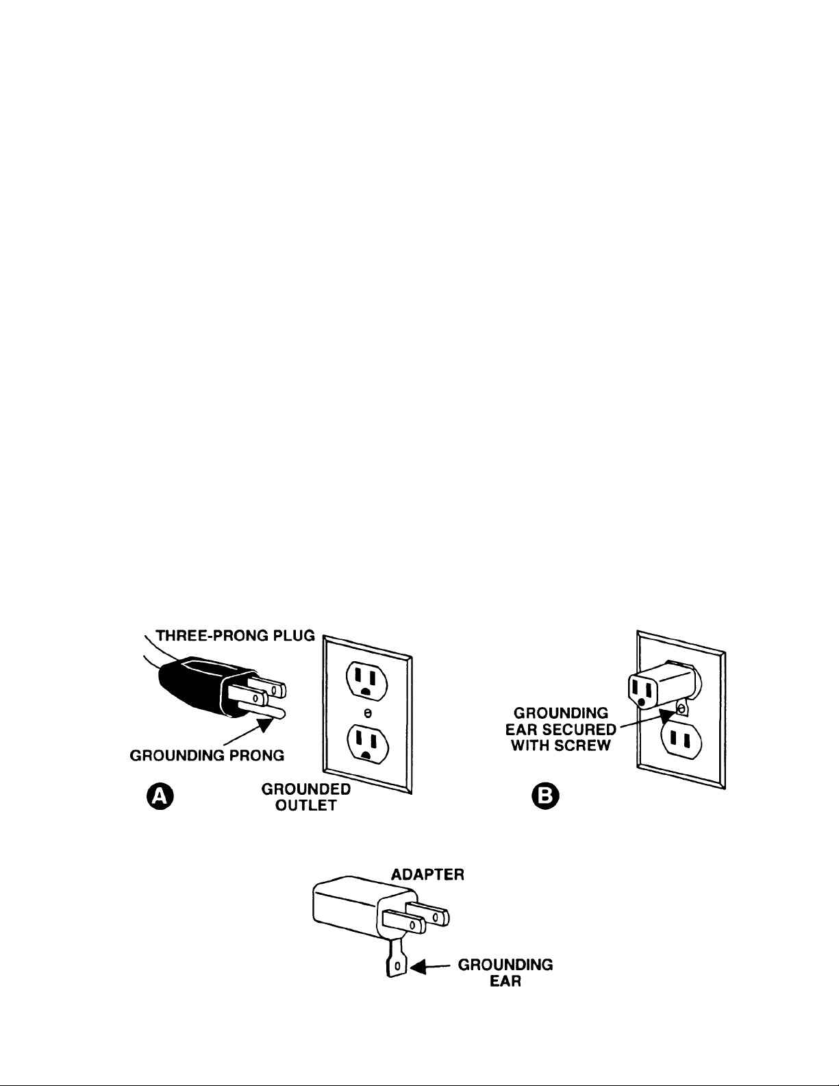
Grounding Instructions
Caution: This tool must be grounded while in use to protect the operator from electric shock.
In the event of a malfunction or br eak down, grounding provides a path of least resistance for electr ic
current to r educ e the risk of electri c shock. This tool is equipped with an elec tric cord having an
equipment -grounding conductor and a gr ounding plug. T he plug must be pl ugged into a mat ching outlet
that is properly installed and grounded in accor danc e with all local codes and ordinanc es.
Do not modi fy the plug provided. If it will not fit the outlet, have the proper outlet installed by a quali fied
electrician.
Improper connection of the equipment-grounding c onduc tor can result in a risk of electri c shock. The
conductor, with insulati on havi ng an outer surface t hat is green with or without yellow stri pes, is the
equipment -grounding conductor . If r epair or replac ement of the electric cord or pl ug is necessary, do not
connect the equi pment-grounding conductor to a live term inal.
Check with a qualifi ed electri c ian or serv ice personnel if the groundi ng instructi ons are not c ompletely
understood, or if in doubt as to whether the tool i s properly grounded. Use only three wire ext ensi on
cords that have three-prong grounding plugs and three-pole receptacl es that accept the t ool’s plug.
Repair or replace a damaged or worn cord immediately.
115 Volt Operation
As received from the factory, your drill press is ready to run at 115 v olt operation. This drill press, when
wired for 115 volt, is int ended for use on a circ uit that has an outlet and a plug that looks li k e the one
illustrated in (A). A temporary adapter, which look s like the adapter as illustrated in (B), may be used to
connect thi s plug to a two-pole recept acle, as shown in (B) if a properly gr ounded outlet i s not avai lable.
The tempor ary adapter should only be used unt il a properl y grounded outlet can be installed by a
qualified elec trici an. This adapter is not applicable in Canada. The green colored rigid ear, lug, or
tab, extending f r om the adapter, must be connected to a permanent gr ound such as a properly grounded
outlet box, as shown in (B).
5
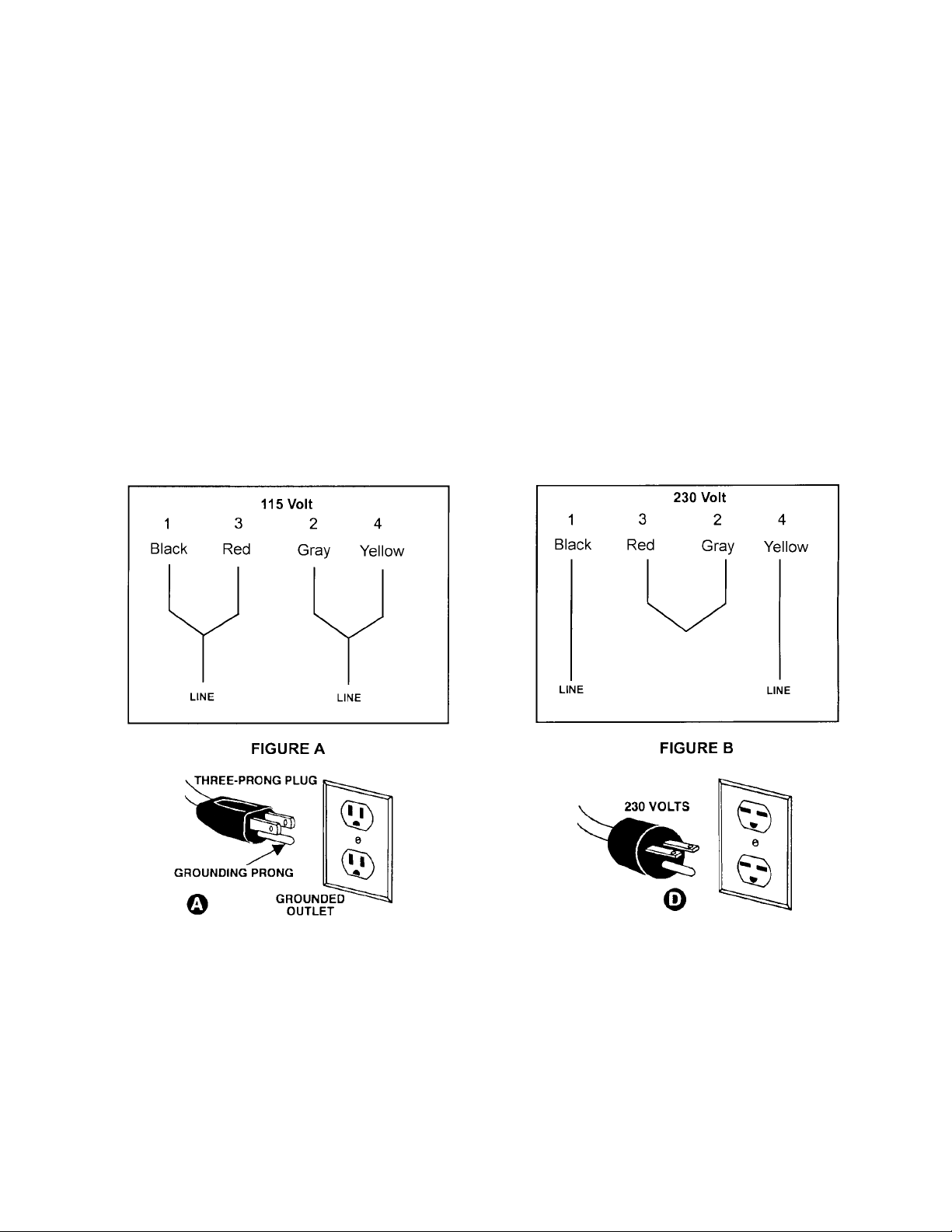
230 Volt Operation
If 230V, single phase operati on is desired, the following instructions must be fol lowed:
1. Disconnect the machine f rom the power source.
2. This JET drill press is supplied with f our motor leads that are connected for 115V operat ion, as
shown in Figure A. Rec onnec t these four motor leads for 230V operati on, as shown in Figure B.
3. The 115V attachment plug (A) , supplied with t he dr ill press, must be replaced with a UL/CSA listed
plug suitable for 230V operation (D). Contact your l oc al Authoriz ed JET Service Cent er or qualif ied
electrician for proper procedures to install t he plug. The drill press must comply with all local and
national c odes after the 230 volt plug is installed.
4. The drill press with a 230 volt plug should only be connected to an out let having the sam e
confi gur ation (D). No adapter is available or should be used with the 230 volt plug.
Important: In all c ases (115 or 230 volt s), make certain the receptac le in question is properly grounded.
If you ar e not sure, hav e a r egistered elect r ician check the receptacl e.
6
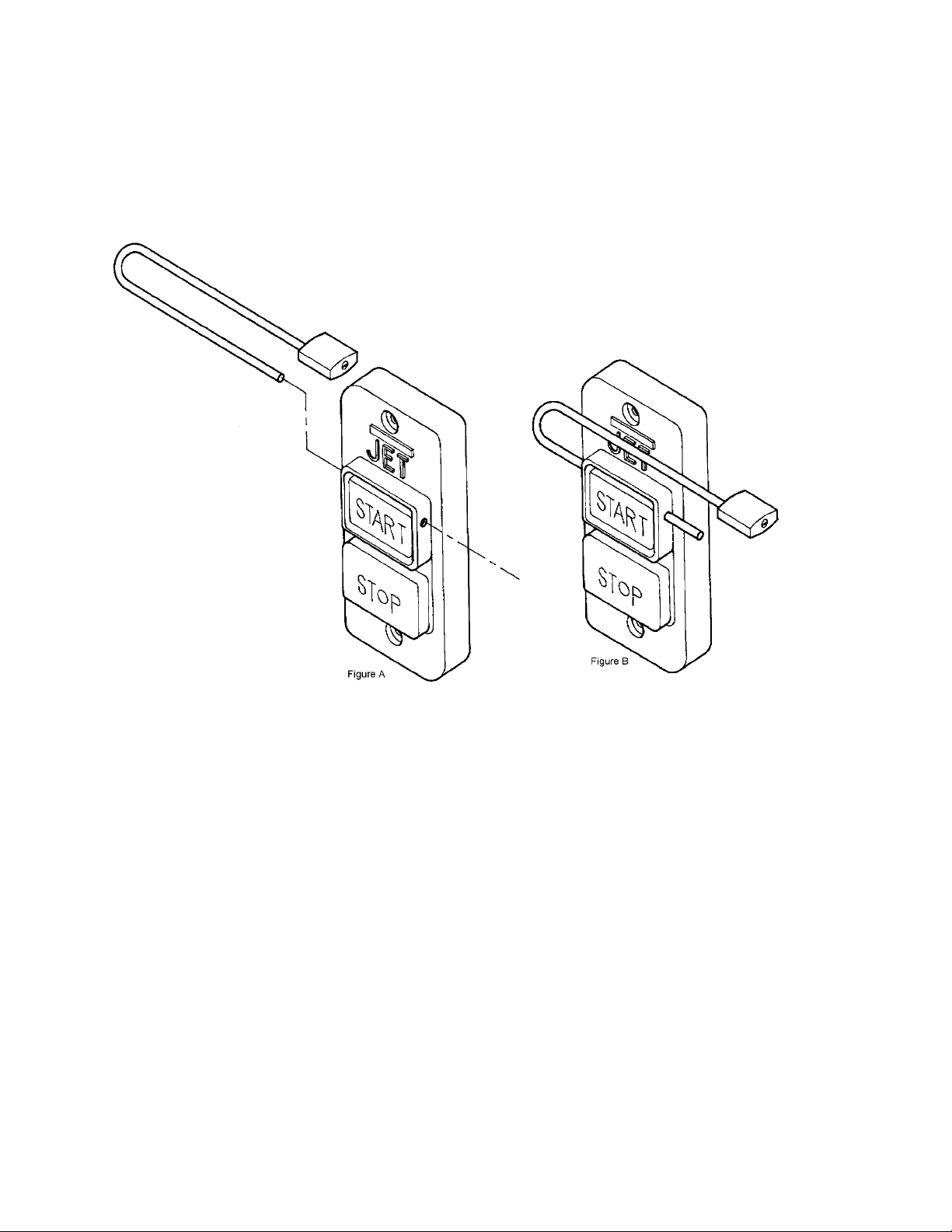
On-Off Switch Padlock
Model No . BP-1, Sto ck No. 709736
To safeguard your machine from unaut hor ized operati on and to avoid accidental starting by y oung
children, the use of a padl oc k is highly rec ommended. J E T model B P - 1 is avai lable from your local
authorized JET distri butor or by calling JET E quipment & Tools at 800-274-6848.
To lock out an on-off switch:
1. Open the padlock. See Fig. A.
2. Insert through holes i n the start button. S ee Fig. B
3. Close the padlock.
4. Place the key in a safe place.
7

Specifications: JDP-17MF
Stock Number................................................................................................................................354169
Swing.............................................................................................................................................16-1/2”
Type..................................................................................................................................................Floor
Drilling Capacity ..................................................................................................................................5/8”
Chuck Size..........................................................................................................................................5/8”
Spindle Travel..................................................................................................................................4-3/8”
Spindle Distance to Base......................................................................................................................49”
Spindle Distance to Table (max.)....................................................................................................29-1/8”
Table Size Di ameter.......................................................................................................................13-3/4”
Table Tilt....................................................................................................................................+ or - 45°
Spindle T aper ....................................................................................................................................MT-2
Column Diameter .............................................................................................................................3-1/8”
Number of Spindle S peeds....................................................................................................................16
Range of Spi ndle Speeds ................................................................................................. 200-3,630 RPM
Overall Height...................................................................................................................................... 66”
Base Size........................................................................................................................12-1/2” x 19-5/8”
Motor......................................................................................................................................3/4HP, 1 Ph
...........................................................................................................................115/230V, prewired 115V
Net Weight (approx.) ...................................................................................................................... 189 lb.
Shipping Wei ght (approx. ) .............................................................................................................. 200 lb.
Table of Contents Page
Warranty .................................................................................................................................................2
Warnings ....................................................................................................................... .......................3-4
Grounding Instructions.............................................................................................................................5
115V Operati on .......................................................................................................................................5
230V Operati on .......................................................................................................................................6
On-Off Switch Padl ock ............................................................................................................................7
Specifications..........................................................................................................................................8
Table of Contents....................................................................................................................................8
Contents of Shipping Container...............................................................................................................9
Tools Supplied for Assembly ...................................................................................................................9
Tools Required for Assembly...................................................................................................................9
Before Assembly .....................................................................................................................................9
Assembly..........................................................................................................................................10-11
Removing the Chuck and A r bor.............................................................................................................11
Adjusting the Depth Stop.......................................................................................................................12
Changing Spindle Speeds......................................................................................................................12
Speed and Pulley Char t.........................................................................................................................13
Return Spring Adjustment ......................................................................................................................14
Table Tilt Adjustm ent.............................................................................................................................14
Basic Operation.....................................................................................................................................15
Lubrication.............................................................................................................................................15
Troubleshooting.....................................................................................................................................16
Part’s Breakdown...................................................................................................................................17
Part’s List..........................................................................................................................................18-20
Wiring Diagram .....................................................................................................................................21
The specifications in this manual are given as general informati on and are not binding. WMH TOOL
GROUP r eserv es the ri ght t o eff ect, at any t i m e and without pri or not ic e, changes or al ter ati ons to part s,
fittings, and accessory equi pment deem ed nec essary for any reason whatsoever.
8

Contents of the Shipping Container
1. Head Assembly
1. Table
1. Column and Brack et Assembly
1. Base
1. Owner’s Manual
1. Warranty Registration Card
1. Chuck and Chuck Key
3. Downfeed Handle
1. Table Bracket Lock Handle
1. Table Bracket Raising Handle
4. M10 x 40 Hex Cap Bolts
1. Arbor
1. Drift Key
Tools Supplied for Assembly
1. 3mm Hex W r enc h
1. 5mm Hex W r enc h
Tools Required for Assembly
1. 17mm Box Wrench or a 6”-8” Adjustable
Wrench
WARNING!
Read and understand all assembly
instructions before attempting assembly!
Failure t o comply may cau se serious in jury!
Before Assembly
1. Remove the contents from the shipping
container.
2. Compare the contents of the shipping
container wit h the list f ound above. Report
any shortages or damage to your JET
distributor.
3. Clean all rust protected surfaces with
kerosene or a light solvent. Do not use
lacquer thinner, paint thinner, or gasoline.
These will damage pl astic components and
painted surf aces.
9

Assembly
1. Place the base (A, Fig. 1) on a l evel floor.
2. With a 17mm wrench attach the column
assembly (B, Fig. 1) to the base (A, Fig. 1)
with four M 10 x 40 hex cap bol ts (C, Fi g. 1).
Tighten firmly.
3. Thread lock handle (D, F ig. 2) i nto the t able
bracket (E, Fig. 2).
4. Loosen the set screw (F, Fig. 3) on the
raising handle (G, Fig. 3) with a 3mm hex
wrench.
5. Slide the handle onto the table bracket
shaft.
6. Turn the handle until the set screw is
opposite the flat section on the shaft, and
tighten t he set scr ew to secure t he handle.
7. Insert the table (H, Fig. 3) into the table
bracket.
8. Tighten the t able lock handle (I, Fig. 3).
10

9. With the aid of a second person, carefully
lif t the head ont o the col umn top. Caution:
The head assembly is heavy! Use care
when lifting onto the column!
10. Rotate head assem bly unti l sides of the bel t
cover are parallel with the sides of the base.
11. Tighten two set screws (A, Fig. 4) with a
5mm wrench until they ar e snug.
12. Install three down feed handles (B, Fig. 4)
into the down f eed hub (C, Fig. 4) .
13. Raise table to approximately seven inches
below spindle assem bly, and lock t he table
in place.
14. P lace a piece of scrap wood on the table.
15. T horoughly cl ean spindle, arbor, and chuck.
Important: These three pieces must be
free of any rust protection, or lubricant. If
they are not cl ean, the arbor and chuck will
fail to seat in t he spi ndle.
16. P lace arbor int o the chuck.
17. Twist the chuc k to retract the chuck j aws if
they are exposed.
18. Place arbor and chuck assembly into the
spindle.
19. Turn t he ar bor and chuck assembl y unti l the
tang on the arbor engages the slot at the
end of the spindle.
20. Lower the down feed handle so that the
chuck m eets the scrap wood. Pressure on
the down feed handle once t he chuc k m eets
the scrap wood seats the arbor and chuck
into the spindle, See Figure. 5.
Removing the Chuck and Arbor
1. Unplug machine from the power source.
2. Raise the table unt il it is about seven inchs
below the chuck.
3. Place a piece of scrap wood on the table,
and lower quill using the down feed handle.
4. Rotate spindle to align the key hole in the
spindle with the key hole in the quill.
5. Insert the drift key (D, Fig. 6) into the
aligned slot s and tap l i ghtl y. The chuc k and
arbor assembly should fall from the spindle.
11

Adjusting the Depth Stop
To drill m ultiple holes at the same preset depth,
use the depth stop:
1. Use a penci l to mark the depth the bit will
drill into the workpiece (A, Fig. 7).
2. With the drill bit in the chuck, lower down
feed handle t o advance bit to y our m ark, see
Figure 7.
3. With y our ot her hand, advance the lock nuts
(B, Fig. 7) on the depth stop rod until they
are snug to the seat (C, F ig. 7).
4. The drill bit will now advance to this point.
5. To release, advance the nuts counter-
clockwise to t he top of the dept h stop.
Changing Spindle Speeds
A spindle speed and bel t arrangem ent chart are
found on the i nside of the belt cov er (D, F ig. 8) .
Refer to this chart whenever changing speeds.
To change spindle speeds:
1. Unplug the machine from the power
source.
2. Loosen two bar knobs (E, Fig. 8) found on
each side of t he head assem bly.
3. Rotate the tension adjuster (F, Fig. 8) to
bring t he motor base as close to the head as
possible.
4. Change the belts location according the
speed chart and the speed you desire.
5. Rotate the tension adjuster (F. Fig. 8) to
tension the belts.
6. Ti ghten two bar knobs (E, Fig. 8). Belt s are
properly tensioned when finger and thumb
pressure midway between the two pulleys
causes approximately ½” deflection.
12

Speed & Pulley Chart
13

Return Spring Adjustment
The retur n spring is adjusted at t he factory and
should not need further adjustment. If
adjustment is deemed necessary:
1. Unplug the machine from the power
source.
2. Loosen two jam nuts (A, Fig. 9). Do not
remove.
3. Firmly hold the c oil spring cover (B , Fig. 9).
4. Pull out the cover and rotate until the pin (C,
Fig. 9) on the return spring plate engages
the next not ch i n t he coi l spri ng cover. Turn
the cov er cl oc kwise to decrease tensi on and
counter-clockwise to increase tensi on.
5. Tighten two jam nuts (A, Fig. 9). Do not
over-tighten. Nuts should not contact the
housing when tight. T he j am nuts should be
tightened against eachother.
Work Light
Install a light bulb, no larger than 60 watts into
the socket accessed from beneath the head.
The light bulb is control led by the rocker switch
(D, Fig. 9).
Table Tilt Adjustment
CAUTION!
Remove the ali gnment pin first an d then
loosen t he hex cap bo lt. Failure to comp ly
may cause the tab le assembly to sep arat e
from the column and fall.
To tilt the table:
1. Turn nut (D, Fig. 11) clockwise to pull out
the alignment pin ( E , Fig. 11) .
2. Loosen hex cap bol t ( F, Fi g. 11) , and t il t the
table to t he desired angle.
3. Tighten the hex cap bolt ( F, Fig. 11).
4. The alignment pin only works at 90° and
must be reinserted when the table is
returned to 90°.
14

Basic Operation
• Always use a bac k-up piece of scrap wood
to cover the table. This protects both the
table and the drill bit.
• Place m aterial to be drilled i n such as way
as to com e int o contact with the lef t side of
the column. This prevents the material from
spinning.
WARNING!
If the work piece is n ot large enough to
come into contact wi t h the column, use a
clamp or drill press vise that is securely
fastened to the table!
Failure t o comply may cau se serious in jury!
• Feed the bit into the material with only
enough force to allow the drill bit to work.
Feeding too slowly may cause burning of
the workpiece. Feeding too quickly may
cause the motor to stop and/ or the drill bit to
break.
• Generall y speaking, t he smaller the drill bit,
the greater the RPM required. Wood
requires higher speeds than m etal. Metal is
usually drilled at sl ower speeds.
• In dusty environments, frequently blow out
any dust that accumulates insi de the motor.
Lubrication
Periodic ally lubricat e the gear and the rack, t he
table elevation mechanism, the splines
(grooves) in the spindle, and the teeth of the
quill with a #2 tube grease.
15

Trouble Probable Cause Remedy
Drill press will not start.
Drill press does not come up
to speed.
Drill Press vibrates
excessively.
Noisy Operat ion.
Workpiece Burn s.
Drill bit wanders.
Wood splinters on the
underside.
Drill bit binds in workpiece.
Excessive drill bit runout, or
wobble.
Quill returns too slow, or too
fast.
Chuck, or arbor do not stay in
place.
Troubleshooting
1. Drill press unplugged from
wall, or motor.
2. Fuse blown, or circuit
breaker tripped.
3. Cord damaged.
4. Starting capacitor bad.
1. Extension cor d too light or
too long.
2. Low current.
1. Stand on uneven surface.
2. Bad belt(s).
1. Incorrect belt tension.
2. Dry spindle.
3. Loose spindle pulley.
4. Loose motor pulley.
1. Incorrect Speed.
2. Chips not clearing from hole
or bit.
3. Dull drill bit.
4. Feeding too slow.
1. Bit sharpened incor r ec tly.
2. Bent drill bit.
3. Bit, or chuck not instal led
properly.
1. No backing board used.
1. Workpiece pinching the bit.
2. Excessive feed rat e.
3. Chuck jaws not tight.
4. Improper belt tension.
1. Bent drill bit.
2. Worn spindle bearings.
3. Bit, or chuck not properly
installed.
1. Spring has im pr oper tension.
1. Dirt, grease, etc on arbor,
chuck, or spindle.
1. Check all plug connections.
2. Replace fuse, or reset circui t
breaker.
3. Replace cord.
4. Replace starti ng c apac itor.
1. Replace with adequate siz e
and length cord.
2. Contact a quali fied
electrician.
1. Adjust stand so that it rests
evenly on the f loor.
2. Replace belts.
1. Adjust belt tension. See
“Changing Spi ndle Speeds”,
page 12.
2. Lubricate spindle. See
“Lubricat ion” page 15.
3. Check tightness of r etaining
nut on pulley , and tighten if
necessary.
4. Tighten set screws in pulleys.
1. Change to appropriate
speed, see speed and pulley
chart, page 13.
2. Retract drill bit f requently to
remove chips.
3. Resharpen, or replace drill
bit.
4. Increase feed rat e.
1. Resharpen bit correct ly.
2. Replace drill bit.
3. Reinstall the chuck, or bi t
properly.
1. Place a scrap board
underneath the workpiec e to
prevent splintering.
1. Support or clamp workpiece.
2. Decrease feed rate.
3. Tighten chuck jaws.
4. Increase belt tensi on, see
page 12.
1. Replace drill bit.
2. Replace spindle bearings.
3. Reinstall the bit, or c huc k
properly.
1. Adjust “Return Spr ing
Tension,” page 14.
1. Clean all mating surfaces
thoroughly with a cleaner
degreaser.
16

Parts Breakdown for JDP-17MF
17

Par t s List for J ET JDP-17MF Drill Press
Index Part
No. No. Description Size Qty.
1..........10600111..................... Base.................................................................. ...................................1
2A........12909001A1................. Column and Holder Assy. .................................. ...................................1
3.......... TS-1525021 ................. Set Screw.......................................................... M10x12......................1
5.......... TS-1491061 ................. Hex Cap Bolt..................................................... M10x40 ......................4
6..........10700605A1................. Bracket.............................................................. ...................................1
7..........10600702..................... Pinion Gear....................................................... ...................................1
8..........10600802..................... Gear Shaft......................................................... ...................................1
9..........10600902..................... Worm Pinion ..................................................... ...................................1
10........10601002..................... Crank Handle..................................................... ................................... 1
11........TS-1523031.................Set Screw.......................................................... M6x10........................1
12........10901203A1................. Table Bracket Assy............................................ ...................................1
13........TS-0071011.................Hex Cap Bolt..................................................... 5/8”x1-1/2”..................1
14........10601401..................... Locator Pin........................................................ ...................................1
15........TS-0561011.................Hex Nut............................................................. 1/4"-20........................1
16........10601601..................... Angle Scale....................................................... ...................................1
17........10601702..................... Centering Scale................................................. ...................................1
18........2658MZDU36............... Drive Screw....................................................... ...................................4
19........10601901..................... Column Lock Handle ......................................... ...................................1
20........10602001..................... Table Lock Handle............................................. ...................................1
21........10702112..................... Table................................................................. ...................................1
22........10602205..................... Rack.................................................................. ...................................1
23........10702307A1................. Rack Ring.......................................................... ...................................1
24........TS-1523031.................Set Screw.......................................................... M6x10........................1
25........10902515A1................. Head.................................................................. ...................................1
26........TS-1525021.................Set Screw.......................................................... M10x 12 ......................2
27........10602702..................... Lamp Socket..................................................... ................................... 1
28........2669BZDA37 ...............Pan Head Screw................................................ M6x8..........................2
29........10902905..................... Handle S hift er .................................................... ...................................1
30........10603002A1................. Cam .................................................................. ...................................1
31........TS-1490021.................Hex Cap Bolt..................................................... M8x16........................1
32........10703211..................... Slide Bar (right)................................................. ...................................1
33........10903302..................... Slide Bar Bolt .................................................... ...................................2
34........10703414..................... Motor Base........................................................ 75x125.......................1
35........TS-0720111.................Lock Washer ..................................................... ½”...............................2
36........TS-1540071.................Hex Nut............................................................. M12............................2
37........ ....................................Handle Body (re:17373839) ............................... ...................................1
38........17373839..................... Feed Shaft Assy (#37,38, 39) ............................. ...................................1
39........ ....................................Spring Pi n (re: 17373839).................................. ...................................1
43A......10604303A1................. Handle Bar A ssy................................................ ...................................3
45........10661801..................... Shaft Collar ....................................................... ...................................1
46........10904618..................... Scale................................................................. ...................................1
48........2658MZDU36............... Drive Screw....................................................... ...................................2
49A......10604902A2................. Coil Spring and Cover ....................................... ...................................1
51........10905116..................... Spring Seat........................................................ ...................................1
52........10905203..................... Plate.................................................................. ...................................1
53........TS-0561052.................Hex Nut............................................................. 1/2"-20UNF.................1
54........10605403..................... Quill Set Screw.................................................. ...................................1
55........TS-1540071.................Hex Nut............................................................. M10............................1
56........10905612..................... Quill................................................................... ...................................1
57........10705703..................... Rubber Washer ................................................. ...................................1
58........10905829..................... Spindle.............................................................. ...................................1
59........BB-6205ZZ ..................Ball Bearing....................................................... ...................................1
18

Index Part
No. No. Description Size Qty.
61........BB-6203Z..................... Ball Bearing....................................................... ...................................1
62........10606201..................... Washer.............................................................. ...................................1
63........10606301..................... Lock Nut............................................................ ...................................1
64........10606401..................... Spindle Nut........................................................ ...................................1
65........10706508A1................. Driving Sleeve................................................... ...................................1
66........BB-6205Z..................... Ball Bearing....................................................... ...................................2
67........10706705..................... Collar................................................................. ...................................1
68........10706802..................... Retaining Ring................................................... ...................................2
69........10606904..................... Pulley Set Nut.................................................... ...................................1
70........10607018..................... Spindle Pulley.................................................... ...................................1
71........561766......................... Arbor.................................................................MT2xJT2....................1
72A......561708......................... Chuck................................................................ ...................................1
73........10607303..................... Wedge............................................................... ...................................1
74........8907522151.................Motor................................................................. ...................................1
............ 82061041.....................Motor Fan (not shown)....................................... ...................................1
............ 89075161.....................Motor Fan Cover (not shown) ............................ ...................................1
............ 299155BA04 ................ Centrifugal Switch (not shown)........................... ...................................1
............ 2992A55A14 ................ Capacitor ( not shown) ........................................ ...................................1
75........2808B530C3................Motor Cable....................................................... ...................................1
76........TS-1490041.................Hex Cap Bolt..................................................... M8x25........................4
77........TS-0680031.................Flat Washer....................................................... 5/16”...........................8
78........TS-1540061.................Hex Nut............................................................. M8..............................4
79........10607970A1................. Motor Pulley ...................................................... ...................................1
80........2571NNC109 ............... Parallel Key....................................................... ...................................1
81........TS-1524011.................Set Screw.......................................................... M8x8..........................1
83........12201501..................... Wire Clip ........................................................... ...................................3
84........TS-1533042.................Pan Head S c rew................................................ M5x12 ........................3
85........2807AB08D4................Power Cable...................................................... ...................................1
87........DC1200-44................... On-Off Switch.................................................... ...................................1
88........10608813..................... Switch Box ........................................................ ...................................1
89........TS-1533052.................Pan Head S c rew................................................ M5x16 ........................2
90........10909012A1................. Pulley Cover Assy ............................................. ...................................1
92........2638BZDA40 ...............Round Head Screw............................................ M6x16 ........................4
95........10609510..................... Center Pulley..................................................... ...................................1
96........BB-6202Z..................... Ball Bearing....................................................... ...................................2
98........10609801..................... Center Pulley Shaft............................................ ...................................1
99........VB-A25........................V-Belt ................................................................ A25.............................1
101......TS-0680021.................Flat Washer....................................................... 1/4".............................4
106......TS-0561052.................Hex Nut............................................................. 1/2"-20UNF.................1
112......10611201..................... Chuck Key Holder.............................................. ...................................1
113......2668BBDA40 ............... Pan Head Screw ................................................ M6-1.0x16 ..................1
119......VB-A25........................V-Bel t ................................................................ A25.............................1
128......2653MBDE15............... Tapping Scr ew................................................... ...................................2
131......CK-16.......................... Chuck Key......................................................... ...................................1
137......10308846..................... Switch Cover..................................................... ...................................1
138......TS-1533042.................Pan Head Screw................................................ M5x12........................2
139......2852D55723................. Bulb Switch........................................................ ...................................1
140......10714001..................... Motor Bar (left).................................................. ...................................1
149......2536MBE616 ............... Spring Pin.......................................................... ...................................2
150......10916904..................... I.D. Label........................................................... ...................................1
162......10216210..................... Warning Label................................................... ...................................1
163......2658MZDU36............... Drive Screw....................................................... ...................................4
165......10616519..................... Speed Chart ...................................................... ...................................1
19

Index Part
No. No. Description Size Qty.
169......11316904..................... Nameplate......................................................... ...................................1
601......TS-1533032.................Pan Head Machine Screw.................................. M5x10........................1
602......2504MBC005...............Tooth Washer.................................................... ...................................1
607......TS-0720101.................Lock Washer .....................................................7/16”...........................2
610......TS-1503081.................Socket Head Cap Sc rew.................................... M6x35........................2
611......10661102..................... Seat................................................................... ...................................1
612......TS-1540081.................Hex Nut............................................................. M12............................1
613......10661301..................... Scale Bolt.......................................................... ...................................1
614......13005701..................... Nut .................................................................... ...................................2
615......13005601..................... Washer.............................................................. ...................................1
616......TS-1504051.................Hex Socket Cap Screw...................................... M8x25 ........................1
617......10761701..................... Set Ring ............................................................ ...................................1
618......10604505..................... Round Nut ......................................................... ...................................1
700......TS-152704...................Hex Wrench......................................................3MM...........................1
701......TS-152706...................Hex Wrench......................................................5MM...........................1
801......28065558U4................. Bulb Wire .......................................................... ...................................2
903......2801CBHA01...............Cable Protection................................................ ...................................2
20

21
 Loading...