

Page 1
OWNER'S MANUAL
DC-1900C Dust Collector
JET EQUIPMENT & TOOLS, INC. P.O. BOX 1349 Phone:253-351-6000
A WMH Company Auburn, WA 98071-1349 Fax: 1-800-274-6840
Page 2

This manual has been prepared for the owner and operators of JET’S DC-1900C. Its purpose, aside
from machine operation, is to promote safety through the us e of accepted correct operating and
maintenance procedures. Completely read the safety and maintenance instructions before operating or
servicing the machine. To obtain maximum life and efficiency from your Dust Collector, and to aid in
using the machine safely, read this manual thoroughly and follow instructions carefully.
Warranty & Service
The JET Group warrants every product it sells. If one of our tools needs service or repair, one of our
Authorized Repair Stations located throughout the United States can give you quick service.
In most cases, any one of these JET Group Repair Stations can authorize warranty repair, assist you in
obtaining parts, or perform routine maintenance and major repair on your JET, Performax or Powermatic
tools.
For the name of an Authorized Repair Station in your area, please call 1-800-274-6848.
More Information
Remember, the JET Group is consistently adding new products to the line. For complete, up-to-date
product information, check with your local JET Group distributor.
JET Group Warranty
The JET Group (including Performax and Powermatic brands) makes every effort to assure that its
products meet high quality and durability standards and warrants to the original retail
consumer/purchaser of our products that each product be free from defects in materials and
workmanship as follow: 1 YEAR LIMITED WARRANTY ON ALL PRODUCTS UNLESS SPECIFIED
OTHERWISE. This Warranty does not apply to defects due directly or indirectly to misuse, abuse,
negligence or accidents, normal wear-and-tear, repair or alterations outside our facilities, or to a lack of
maintenance.
THE JET GROUP LIMITS ALL IMPLIED WARRANTIES TO THE PERIOD SPECIFIED ABOVE, FROM
THE DATE THE PRODUCT WAS PURCHASED AT RETAIL. EXCEPT AS STATED HEREIN, ANY
IMPLIED WARRANTIES OR MERCHANTIBILITY AND FITNESS ARE EXCLUDED. SOME STATES
DO NOT ALLOW LIMITATIONS ON HOW LONG THE IMPLIED WARRANTY LASTS, SO THE ABOVE
LIMITATION MAY NOT APPLY TO YOU. THE JET GROUP SHALL IN NO EVENT BE LIABLE FOR
DEATH, INJURIES TO PERSONS OR PROPERTY, OR FOR INCIDENTAL, CONTINGENT, SPECIAL,
OR CONSEQUENTIAL DAMAGES ARISING FROM THE USE OF OUR PRODUCTS. SOME STATES
DO NOT ALLOW THE EXLUSION OR LIMITATION OF INCIDENTAL OR CONSEQUENTIAL
DAMAGES, SO THE ABOVE LIMITATION OR EXCLUSION MAY NOT APPLY TO YOU.
To take advantage of this warranty, the product or part must be returned for examination, postage
prepaid, to an Authorized Repair Station designated by our office. Proof of purchase date and an
explanation of the complaint must accompany the merchandise. If our inspection discloses a defect, we
will either repair or replace the product, or refund the purchase price if we cannot readily and quickly
provide a repair or replacement, if you are willing to accept a refund. We will return repaired product or
replacement at JET’S expense, but if it is determined there is no defect, or that the defect resulted from
causes not within the scope of JET’S warranty, then the user must bear the cost of storing and returning
the product. This warranty gives you specific legal rights; you may also have other rights which vary
from state to state.
The JET Group sells through distributors only. Members of the JET Group reserve the right to effect at
any time, without prior notice, those alterations to parts, fittings, and accessory equipment which they
may deem necessary for any reason whatsoever.
2
Page 3

WARNING
1. Read and understand the entire contents of this manual before attempting assembly or
operation. Do not use this machine until proper training and knowledge has been obtained.
2. Do not leave Dust Collector when plugged in. Unplug from outlet when not in use and before
servicing.
3. Do not use outdoors or on wet surfaces.
4. Do not allow to be used as a toy. Close attention is necessary when used near children.
5. Use only as described in this manual. Use only manufacturer’s recommended attachments.
6. Do not use with damaged cord or plug. If Dust Collector is not working as it should, has been
dropped, damaged, left outdoor, or dropped in water, return it to a service center.
7. Do not pull or carry by cord, use cord as a handle, close a door on cord, or pull cord around sharp
edges or corners. Do not run Dust Collector over cord. Keep cord away from heated surfaces.
8. Do not unplug by pulling on cord. To unplug, grasp the plug, not the cord.
9. Do not handle plug or Dust Collector with wet hands.
10. Do not put any objects into the openings. Do not use with any opening blocked; keep free of dust,
lint, hair, and anything that may reduce air flow.
11. Keep hair, loose clothing, fingers, and all parts of body away from opening and moving parts.
12. Do not pick up anything that is burning or smoking, such as cigarettes, matches, or hot ashes.
13. Do not use without dust bag and/or filters in place.
14. Turn off all controls before unplugging.
15. Do not use to pick up flammable or combustible liquids such as gasoline or use in areas where they
may be present.
16. Do not operate without hose connected to the inlet ports or covered by an inlet cap. Hazardous
moving parts inside. Unplug machine before removing inlet port, inlet cap, hose, or inlet guard.
17. Use the inlet caps to cover the inlet port openings that are not connected to hoses.
18. Some dust created by power sanding, sawing, grinding, drilling andother constructionactivities
contains chemicals known to cause cancer, birth defects or other reproductive harm. Some
examples of these chemicals are:
• Lead from lead based paint
• Crystalline silica from bricks and cement andother masonryproducts, and
• Arsenic and chromium from chemically-treated lumber.
19. Your risk from those exposures varies, depending on how often you do this type of work. To
reduce your exposure to these chemicals: work in a well ventilated area, and work with approved
safety equipment, such as those dust masks that are specifically designed to filter out microscopic
particles
20. Do not operate tool while under the influence of drugs, alcohol or any medication.
21. Make sure the extension cord is in good condition. When using an extension cord, be sure to use
one heavy enough to carry the current your product will draw. An undersize cord will cause a drop
in the line voltage resulting in loss of power and overheating. The table below shows the correct
size to use depending on cord length and nameplate ampere rating. If in doubt, use the next
heavier gauge. The smaller gauge number, the heavier the cord.
22. Do not use dust collector for anything except wood dust. Materials such as liquids, metal shavings,
metal dust, screws, glass, plastic or rock can cause sparks and/or damage when coming into
contact with any part of the dust collector.
23. Ground your dust collector along all plastic componets. The connection of bare 12 gauge copper
wire on all plastic hoses, fittings and blast gates to all machines will help reduce the occurrence of
static build up and discharge.
SAVE THESE INSTRUCTIONS
3
Page 4

Specifications: DC-1900C
Stock Number..............................................................................................................................708637C
Blower Wheel Diameter........................................................................................................................14"
Sound Rating at 3 feet................................................................................................................. 86-92 db
HoseDiameter................................................................................................................................4" & 8”
Air Flow at 8” (CFM).........................................................................................................................1,900
Velocity at 8” (FPM).......................................................................................................................... 5,629
Static Pressure (inch of water)..........................................................................................................12.15
Bag Diameter .......................................................................................................................................20"
Bag Length................................................................................................................................. 48” & 29"
Collector Bag Capacity (cu. ft.).........................................................................................................10.68
Overall Dimensions.............................................................................................58"L x 30"W x 72-1/2"H"
Motor (TEFC) ...........................................................................................................3 HP, 1Ph 230V only
Net Weight (approx.) .....................................................................................................................236 lbs.
Table of Contents Page
Warranty .................................................................................................................................................2
Warnings ....................................................................................................................... ..........................3
Specifications..........................................................................................................................................4
Table of Contents....................................................................................................................................4
Unpacking DC-1900.................................................................................................................................5
Contents of Shipping Carton....................................................................................................................5
Tools Required for Assembly...................................................................................................................5
Assembly..............................................................................................................................................6-8
Electrical Connections .............................................................................................................................9
Turning the Machine On & Off.................................................................................................................9
Maintenance............................................................................................................................................ 9
Cleaning the Filter Bag......................................................................................................................9
Removing the Collector Bag..............................................................................................................9
Motor.................................................................................................................................................9
Connecting the Dust collector to a Machine .............................................................................................9
Grounding the Dust Collection System.....................................................................................................9
Parts Breakdown and Parts List........................................................................................................10-12
Wiring Diagrams....................................................................................................................................12
The specifications in this manual are given as general information and are not binding. JET Equipment
& Tools reserves the right to effect, at any time and without prior notice, changes or alterations to parts,
fittings, and accessory equipment deemed necessary for any reason whatsoever.
4
Page 5
WARNING
Read and understand the entire contents of
this manual before attempting assembly or
operation of the dust collector!
Failure to comply may cause serious injury!
Unpacking
1. Remove all contents from the shipping
carton.
2. Report any damage to your distributor.
3. Do not discard any shipping material until
after the dust collector has been assembled
and is running properly.
Contents of the Shipping Cartons
Canister Filter Box (2)
1. Canister Filter
1. Handle
1. Bag of Hardware for Handles
2. M10 Hex Nuts
2. M10 Flat Washers
1. M10 Lock Washer
4. Knobs
DC-1900C
1. Base
1. Owner's Manual
1. Warranty Card
1. Motor/Fan Assembly
10. Collector Bags
2. Snap Rings
4. Casters
1. Inlet Port & Inlet Caps
2. Support Legs
1. Left Housing
1. Right Housing
2. Upper Gaskets
1. Lower Gasket
1. Connector Tube
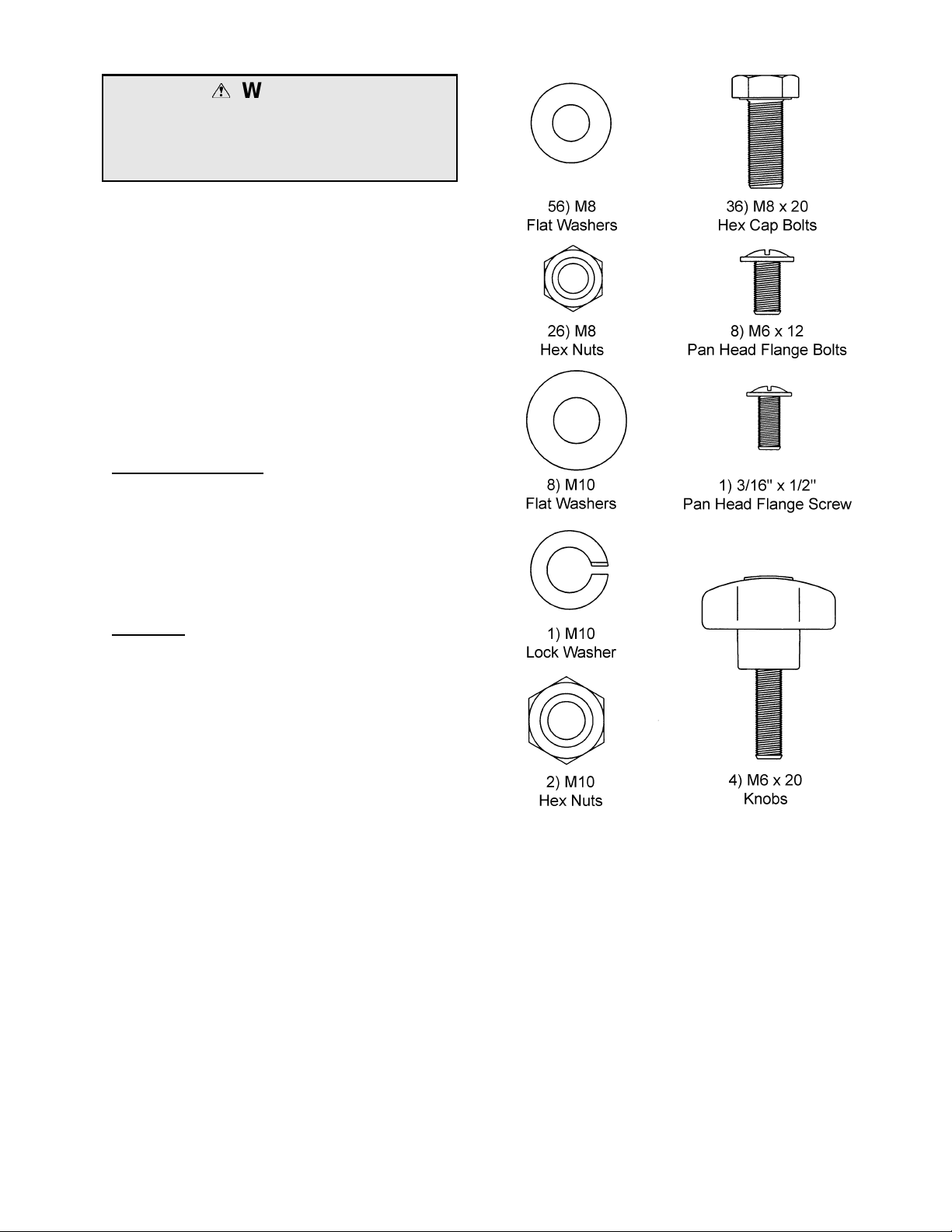
1. Bag of Assembly Hardware
36. M8 x 20 Hex Cap Bolts
56. M8 Flat Washers
6. M10 Flat Washers
8. M6 x 12 Pan Head Flange Bolts
26. M8 Hex Nuts
1. 3/16” x 1/2" Pan Head Flange Bolt
Tools Required for Assembly
2. 13mm Wrenches or Sockets
1. 14mm Wrench or Socket
1. #2 Cross Point Screw Driver
1. 17mm Wrench
5
Page 6
Assembly
WARNING
The dust collector must be disconnected
from the power source during assembly,
unplug. Failure to comply may result in
serious injury!
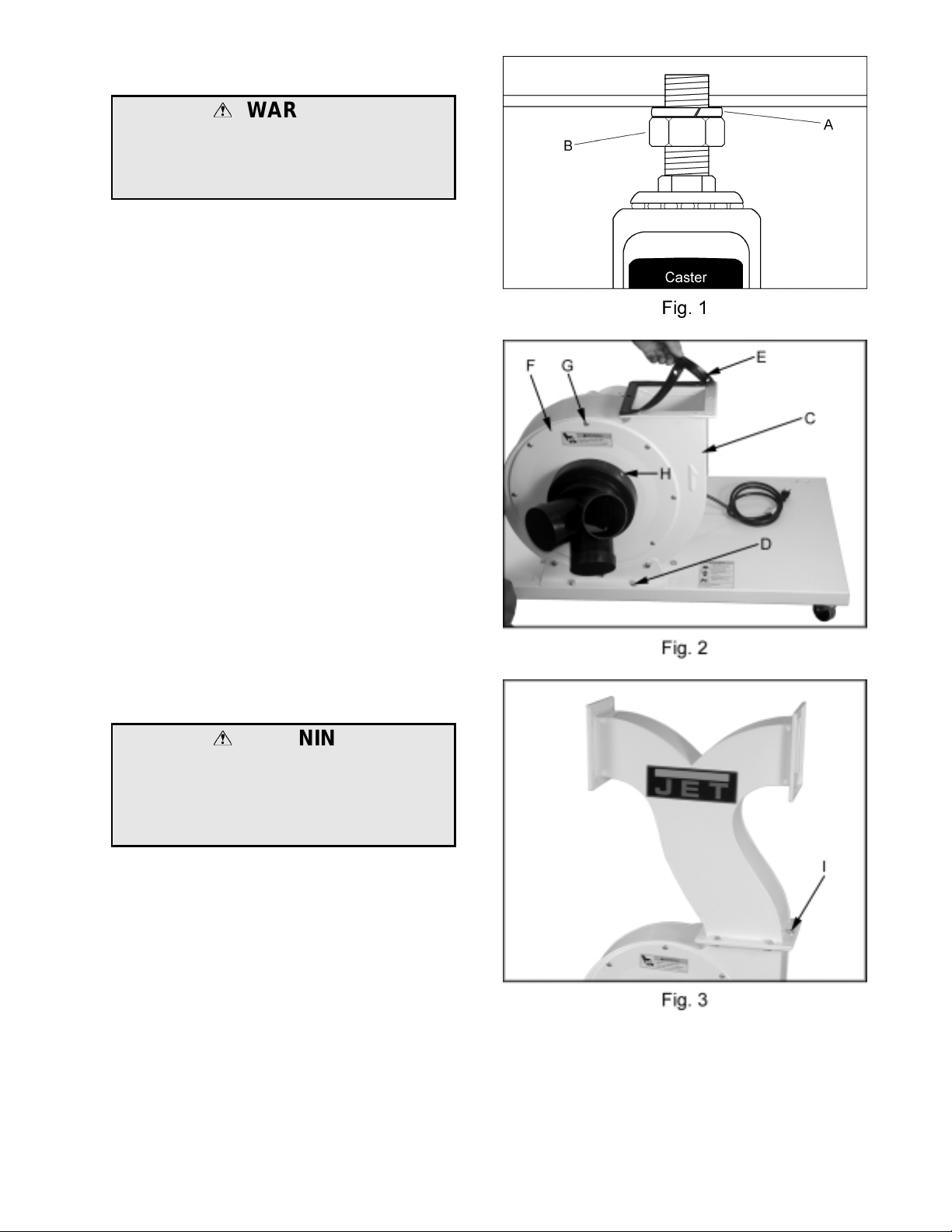
1. Install four casters to the under side of the
base as pictured in Fig. 1. Thread the hex
nut (B, Fig. 1) onto the caster shaft. Then
slide the lock washer (A, Fig. 1) ov er the
caster shaft. Thread the caster shaft into
the threaded hole on the underside of the
base, turn until snug. Tighten the nut (B,
Fig. 1) against the base with a 14mm
wrench. This will give the caster proper
clearance.
2. Place the base with casters on the ground.
Attach the motor and fan assembly (C, Fig.
2) to the base using six M8 x 20 hex cap
bolts, six larger M10 flat washers (D, Fig. 2),
and a 13mm wrench.
3. Place the gasket (E, Fig. 2) on the fan
housing. Line up the pegs on the gasket
with the holes in the housing.
4. Attach inlet guard (F, Fig. 2) to fan housing
using eight M6 x 12 pan head screw s (G,
Fig. 2). Press the inlet port onto the inlet
guard until it snaps into place. Secure in
place with a 3/16” x 1/2" pan head flange
screw (H, Fig. 2).
WARNING
To reduce the risk of injury from moving
parts, always keep inlet port covered with
the caps provided, if they are not
connected to a hose. Failure to comply
may result in serious injury!
5. Attach connector tube to fan housing using
six M8 x 20 hex cap bolts, twelve M8 flat
washers, six M8 hex nuts (I, Fig. 3), and a
13mm wrench. Be sure connector tube
faces the proper direction, as s hown in
Figure 3.
6
Page 7
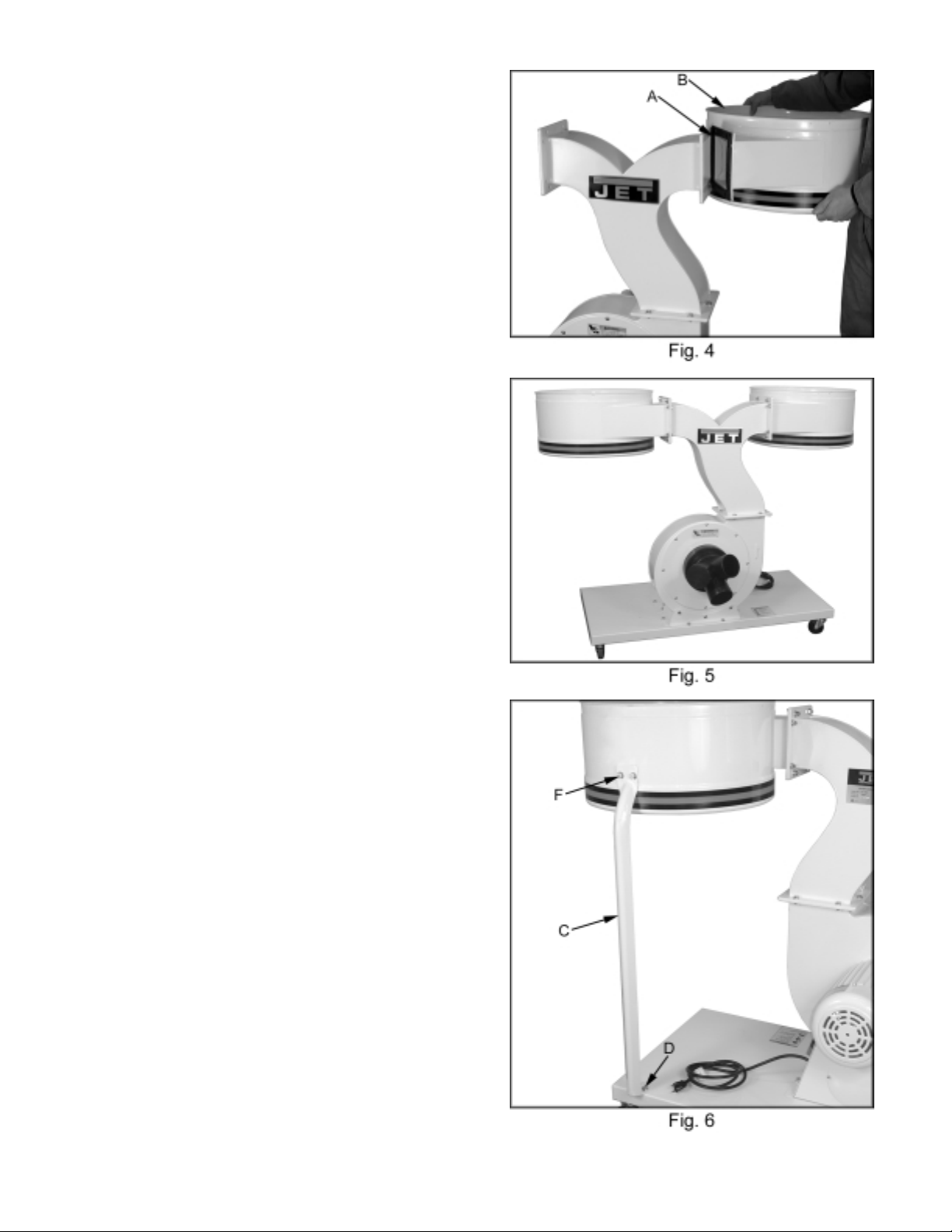
6. Place the gasket (A, Fig. 4) between the
housing and connector tube. Line up the
pegs on the gasket with the holes in the
housing.
7. Attach the collector housing (B, Fig. 4) to
connector tube with eight M8 x 20 hex cap
bolts, sixteen M8 flat washers, and eight M8
hex nuts . Be sure that inside deflector of
the housing points down toward the collector
bag.
Note: There are two holes in the housing
that need to be on the same side as the two
holes in the base.
8. Repeat for opposite side, see Figure 5.
9. Attach support bracket (C, Fig. 6) to base
using two M8 x 20 hex cap bolts and two
M8 flat washers, (D, Fig. 6). Do not tighten
at this time.
10. Align holes and secure to canister with two
M8 x 20 hex cap bolts, four flat washers,
and two hex nuts, (F, Fig. 6).
11. Tighten the two bolts holding the s upport to
the base.
12. Repeat for opposite side.
7
Page 8
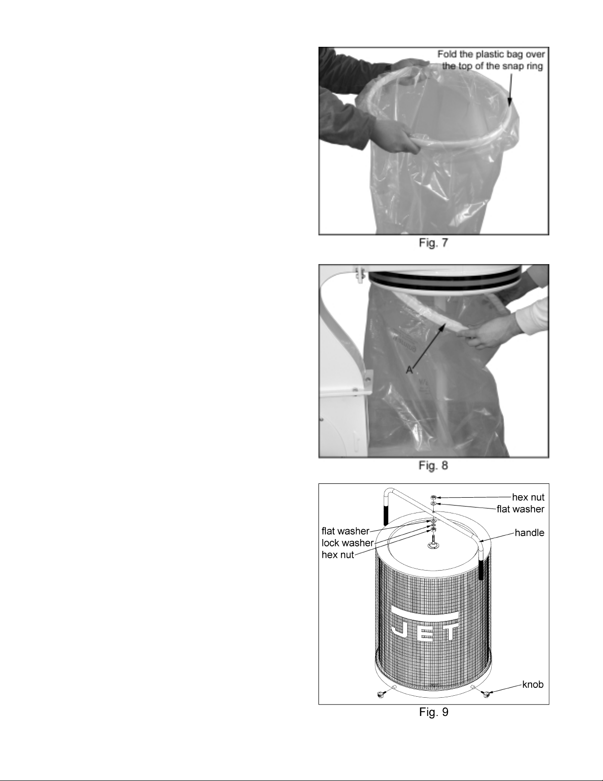
13. Place the ring over the top of the plastic bag
and fold over the bag approximately three
inches, Figure 7.
14. Insert the snap ring (A, Fig. 7) of the
collector bag into the bottom of the housing
at an angle.
15. Pull down on the ring to make sure it “seats”
in the housing.
Note: make sure the snap ring “s naps” into
place in the housing, and also that the
plastic bag hangs down approximately 3” so
that there are no air leaks.
16. Repeat for opposite side.
17. Mount the handle onto the canister filter with
two M10 hex nuts, two M10 flat was hers ,
and a M10 lock washer, see Figure 9.
18. Repeat for the opposite side.
8
Page 9
Electrical Connections
WARNING
All electrical connections must be done by a
qualified electrician. A ll adjustments or
repairs must be done with the dust collector
disconnected from the power source,
unplugged. Failure to comply may result in
serious injury!
Removing the Collector Bag
CAUTION
Wearing a particle mask/respirator for
protection against fine dust particles during
cleaning is highly recommended.
1. Disconnect the machine from the power
source, unplug.
The DC-1900-1 dust collector is rated at 230V
Only and is not supplied with a plug. Use a
plug and outlet rated at least 20 amps. The
circuit for the machine should also be protected
by at least a 20 amp circuit breaker or fuse.
Keep in mind that a curcuit being used by other
machines, tools, lights, heaters, etc. at the same
time will add to the electrical load. A dedicated
curcuit to the dust collector will give you the
best results since dust collectors are generally
used at the same time other tools are running.
Before hooking up to the power source, make
sure that the switch is in the off position.
Turning the M achine On & Off
Before hooking up to the power source, make
sure that the switch is in the off position.
The dust collector can be turned on by pressing
the start button mounted next to the motor.
Press the stop button to turn off the dust
collector.
Maintenance
WARNING
Never perform maintenace on this machine
before turning switch off and removing plug
from power source, unplug.
Failure to comply may cause serious injury!
2. Remove the collector bag by pushing the
ring of the collector bag upwards at an angle
and pulling the bag and snap ring out.
3. Empty the contents into an appropriate
container.
4. See Page 8 for details on replacing the
collector bags.
Motor
Make frequent inspections of the motor fan and
blow out (with low pressure air hose) or vacuum
any accumulation of foreign material in order to
maintain normal motor ventilation.
Connecting the Dust collector to a
Machine
Use the proper type hose to connect the dust
collector to the machine being operated. Dryer
vent hose is not acceptable for this purpose.
Contact your nearest JET distributor for the full
line of JET Dust Collector Hoses and
Accessories. Customize your installation and
obtain maximum performance with JET's dust
hoods, hoses, clamps, fittings, and blast gates.
You can also purchase the JET “Dust Collection
Basics Video” stock # JW1050V through your
JET Distributor
Cleaning the Filter
Clean both the filter and collector bags
frequently to keep the collector's performance at
its optimum.
To clean the filter turn the handle a couple
rotations so the dust falls into the collector bag.
Grounding the Dust Collection System
The dust collection system includes the dust
collector and the hose, or duct work you use to
connect the tools. The dust collector is grounded
though the ground wire in the cord. The hose or
duct work you use to connect the tool to the dus t
collector must also be grounded. To assist in
grounding your system you can purchase the JET
“Dust Collector Grounding Kit” stock # JW1053,
and also the JET “Dust Collection Basics Video”
stock # JW1050V through JET Distributors.
9
Page 10
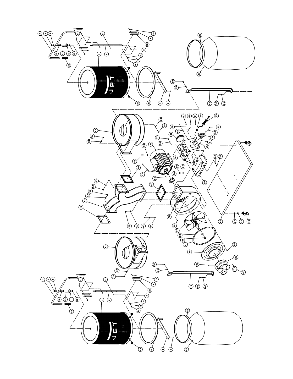
Parts Breakdown
10
Page 11

Parts List for the DC-1900C Canister Filter
Index Part
No. No. Description Size Qty.
1.......... 708739......................... Filter...................................................... ...............................................2
2.......... 331010......................... Shaft...................................................... ...............................................2
3.......... 331012......................... Scraper.................................................. ...............................................4
4.......... 331015......................... Plate...................................................... ...............................................4
5.......... 331009......................... Support.................................................. ...............................................2
6.......... ST049200 .................... Tapping Screw.......................................M4x8.......................................8
7.......... 331050......................... Handle................................................... ...............................................2
8.......... NH101700.................... Nut ........................................................M10.........................................4
9.......... WF102025................... Flat Washer...........................................M10.........................................4
10........WS100000...................Spring Washer.......................................M10.........................................2
11........331014.........................Bracket.................................................. ...............................................2
12........150623.........................Pad........................................................ ...............................................2
13........BR000052.................... Rivet...................................................... ...............................................6
14........SH060400.................... Hex Head Bolt.......................................M6x20.....................................8
15........WS060000...................Spring Washer.......................................M6 ..........................................8
16........WF061310 ................... Flat W asher...........................................M6 ..........................................8
17........NH061000.................... Nut........................................................M6 ........................................16
18........331017.........................Plate...................................................... ...............................................4
19........SH069300.................... Hex Head Bolt.......................................M6x12.....................................8
20........331037.........................Knob......................................................M6x20.....................................8
21........331031.........................Pad........................................................ ...............................................2
22........331051.........................Soft Grip Handle.................................... ...............................................4
26........331038.........................Snap Ring.............................................. ...............................................2
27........998674-36.................... PVC Bag ............................................... .............................................10
28........431018W ..................... Impeller Housing.................................... ...............................................1
29........431019W ..................... Impeller Housing Bracket....................... ...............................................1
30........431020W ..................... Motor Bracket........................................ ...............................................1
31........450038.........................Bracket Cap........................................... ...............................................1
32........DC1900-20W............... Motor.....................................................3HP, 1Ph 230V Only...............1
............ DC1900-MFC............... Motor Fan Cover (not shown) ................ ...............................................1
............ DC1900-MF ................. Motor Fan (not shown)........................... ...............................................1
............ DC1900-20B ................ Starting Capacitor (not shown)...............600MFD, 125VAC...................1
............ DC1900-CS..................Centrifugal Switch and Rotor (not shown) ..............................................1
33........IM431001..................... Motor Cord ............................................ ...............................................1
34........994542.........................Switch.................................................... ...............................................1
35........DC1900-33................... Power Cord............................................ ...............................................1
36........420051.........................Motor Pad.............................................. ...............................................1
37........431006.........................Impeller.................................................14”..........................................1
38........431008W ..................... Inlet Guard............................................8”............................................1
39........499025.........................Inlet Port................................................3-4”.........................................1
40........420203.........................Inlet Cap................................................ ...............................................2
41........431034.........................Rubber Gasket ...................................... ...............................................1
42........430028W ..................... Base...................................................... ...............................................1
43........402036.........................Pivoting Caster...................................... ...............................................4
44........430004W ..................... Connector Tube..................................... ...............................................1
45........430035.........................Gasket................................................... ...............................................1
46........430036.........................Gasket................................................... ...............................................2
47........430012W ..................... Left Housing.......................................... ...............................................1
48........430020W ..................... Right Housing ........................................ ...............................................1
49........402004W ..................... Support Bar ........................................... ...............................................2
50........998654.........................Strain Relief........................................... ...............................................2
51........990855.........................Pan Head Bolt w/Flange........................3/16 x 1/2”...............................1
52........992021.........................Key........................................................7x7x20....................................1
11
Page 12
Index Part
No. No. Description Size Qty.
53........991213.........................Nut ........................................................3/16” .......................................1
54........TS-1540061.................Nut ........................................................M8 ........................................30
55........TS-0561031.................Nut ........................................................3/8” –16 UNC..........................4
56........TS-0561072.................Nut ........................................................5/8” –18 UNF ..........................1
57........TS-1490011.................Hex Head Bolt.......................................M8x12...................................10
58........TS-1490031.................Hex Head Bolt.......................................M8x20...................................36
59........TS-1490041.................Hex Head Bolt.......................................M8x25.....................................4
60........990855.........................Pan Head Bolt .......................................3/16 x 1/2”...............................1
61........990856.........................Pan Head Bolt .......................................3/16 x 1”..................................2
62........TS-1554041.................Pan Head Bolt W/Fl ange .......................M6x12 ...................................10
63........TS-0680031.................Flat Washer...........................................M8 ........................................64
64........TS-1550071.................Flat Washer...........................................M10.........................................6
65........TS-155010...................Flat Washer ...........................................M16.........................................1
66........TS-0720081.................Spring Washer.......................................M8 ........................................14
67........TS-1551071.................Spring Washer.......................................M10.........................................4
68........WE050000...................Star Washer (Ext).................................. M5 ..........................................4
............ DC1900-30................... Grounding Label (not shown)................. ...............................................1
............ DC1900-31................... Direction Label (not shown) ................... ...............................................1
............ DC1900-ID................... Identification Label (not shown) ............. ...............................................1
............ DC1900-32................... Name Plate (not shown) ........................ ...............................................1
............ DC1900-HP..................Hardware Package(not shown) ............. ...............................................1
............ DC1900-53................... Warning Label (Base - not shown)......... ...............................................1
............ DC1900-54................... Warning Label (Inlet Guard - not shown) ...............................................1
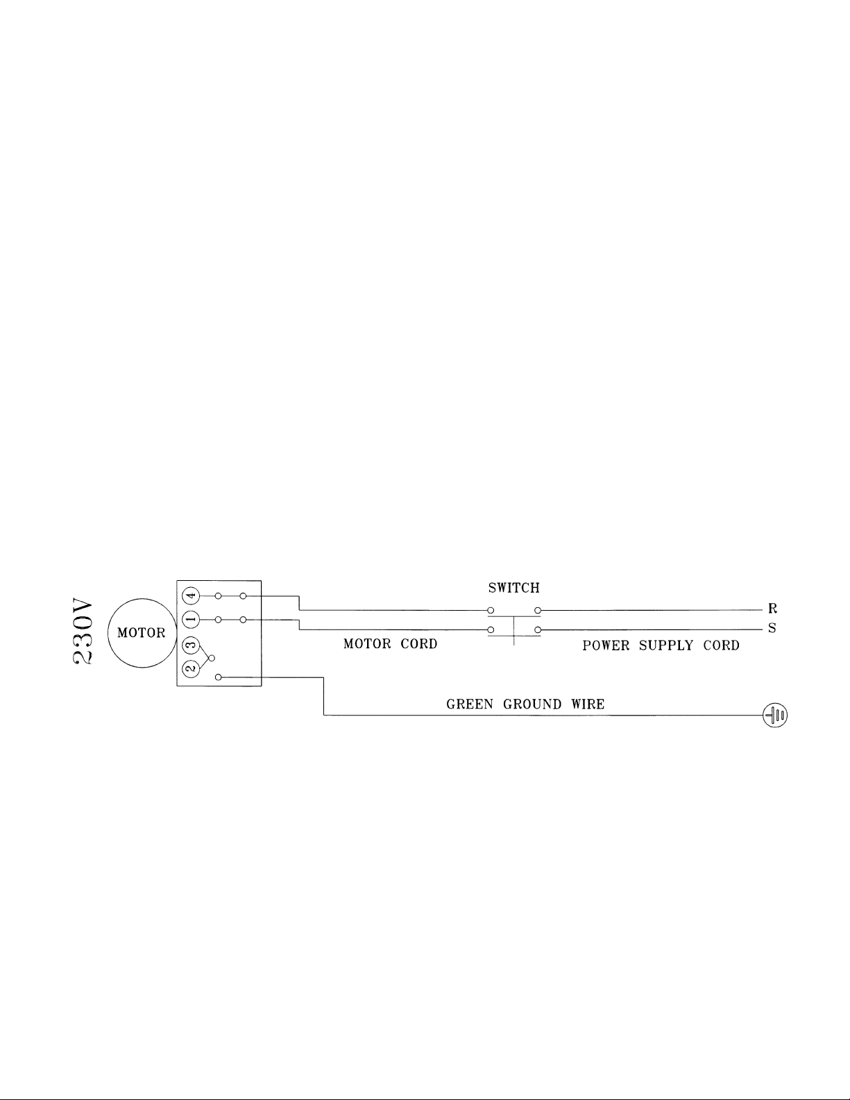
Wiring Diagram For Single Phase 230V Only Dust Collector
12
 Loading...