

Page 1

OWNER’S MANUAL
TM
XACTA-LIFT
and FENCE Assembly
Instructions
For models XLIFT-K or XLIFT-I
Model XLIFT-K shown
P.O. BOX 1349 Phone: 253-351-6000
JET
WMH Tool Gr oup Auburn, W A 98071- 1349 Fax: 1-800-274-6840
www.wmht ool group.com e-mail j et@ wmhtoolgroup.com M-708124 1/03
Page 2

This manual has been prepared for the owner and operat ors of a JET XACTA- Lift. Its purpose, aside from proper
tool operation, is to promote safety through the use of accepted correct operating and maintenance procedures.
Complet ely read the safety and maint enanc e instructions before operating or servicing the tool. To obtain m aximum
life and efficiency from your XACTA-Lif t, and to aid i n usi ng the tool safely, read thi s manual thoroughl y and follow
all instructions carefully.
Warranty & Service
WM H Tool Group warrants every product it sells. I f one of our tools needs servic e or r epair, one of our Authorized
Repair Stations located throughout the United States can give you quick service.
In most cases, any one of these W M H Tool Group Repair Stations can authorize warranty r epair, assist you in
obtaining parts, or perform routine maint enanc e and major repair on your JET, Per formax, Powermatic or Wilton
tools.
For the nam e of an Authorized Repair Station in y our area, call 1- 800- 274- 6848.
More Information
WM H Tool Group is consistently adding new products to the line. For compl ete, up-to-date produc t infor mation,
check with your local WMH Tool G r oup distributor or visit wmhtoolgroup. c om.
Limited Warranty
WM H Tool Group (including JET, P er formax, Powermatic and W ilton brands) makes every ef fort to assure that its
products meet hi gh quality and durability standards and warrants to the original retail consumer/purchaser of our
products that each product be free from defects in materials and workmanship as follows: 1 YEAR LIMITED
WARRANTY ON ALL PRO DUCTS UNLESS SPECIFIED OTHERWISE. This warranty does not apply to defects
due directly or indir ec tly to misuse, abuse, negligence or ac c idents, normal wear-and-tear, repair or alterations
outside our facilities, or to a lack of maintenance.
WMH TOOL GROUP LIMITS ALL IMPLIED WARRANTIES TO THE PERIOD SPECIFIED ABOVE, FROM THE
DATE THE PRODUCT WAS PURCHASED AT RETAIL. EXCEPT AS STATED HEREI N, ANY IMPLIED
WARRANTIES OR MERCHANTI B I LI TY AND F I TNESS ARE EXCLUDED. SO ME STATES DO NOT ALLOW
LIMITATIONS ON HOW LONG THE IMPLIED WARRANTY LASTS, SO THE ABOVE LIMITATIO N MAY NOT
APPLY TO YOU. WMH TOOL GROUP SHALL IN NO EVENT BE LIABLE FOR DEATH, INJURIES TO PERSONS
OR PROPERTY, OR FOR INCIDENTAL, CO NTI NGENT, SPECIAL, OR CONSEQUENTIAL DAMAGES ARISING
FROM THE USE O F OUR PRODUCTS. S OME STATES DO NOT ALLOW THE EXCLUSIO N OR LIMITATION OF
INCIDENTAL OR CONSEQUENTIAL DAMAGES, SO THE ABOVE LIMITATIO N OR EXCLUSION MAY NOT APPLY
TO YOU.
To take advantage of this warranty, the product or part must be returned f or examination, postage prepaid, to an
Authorized Repai r Station designated by our office. Proof of purchase date and an explanation of the complaint
must accompany the merchandi se. If our i nspect ion discloses a defect , WM H Tool Group will either repair or
replace the pr oduc t, or refund the purchase price if we cannot readil y and quickly provide a repair or replacement, if
you are willing to accept a refund. WMH Tool Group will return repaired product or repl acement at our expense, but
if it is determined there i s no defect, or t hat the defect r esul ted from causes not within the scope of our warranty,
then the user must bear the cost of stori ng and r eturning the product. This warranty gives you specif ic legal r ights;
you may al so have other rights, which vary from state to state.
WM H Tool Group sells through distributors only. WMH Tool Group reserves the right to effect at any time, without
prior notice, those alter ations to parts, fittings, and accessory equipment which they may deem necessary for any
reason whatsoever.
2
Page 3

WARNING
Disconnect the table saw from t he power source before attempting any assembly or adjustment . Failur e
to comply may cause serious injury!
Contents of t he XACT A LIFT
(XLIFT-K) shipping carton:
1 XACTA LIFT ( XLIFT-K)
1 Adjustment Handle
1 Phenolic Insert 1-1/2"
1 Insert Wrench
1 5/32 Hex Wrench
1 1/8 Hex Wrench
10 1/4-28 Socket Set Screws
1 Starti ng Pin
1 Aluminum Fence B r ac k et
2 Aluminum Fence E xtensions
2 MDF Sub Fences
1 Hardware Package
2 Fence Clamping Knobs
2 Guard Clamping Knobs
1 Assembly Instructions
1 War r anty Registration Card
Contents of XACTA LIFT
(XLIFT-I) shipping carton:
1 XACTA LIFT
1 Adjustment Handle
1 Insert Wrench
1 Phenolic Insert 1-1/2"
1 5/32 Hex Wrench
1 1/8 Hex Wrench
10 1/4-28 Socket Set Screws
1 Starti ng Pin
1 Assembly Instructions
1 War r anty Registration Card
Mounting your Router to the XACTA LIFT
1. Turn your XACTA LIFT upside down on the table.
With the 5/32 hex wrench supplied, remove t he
four 1/4- 20 x 1 flat head cap screws (Fig. 1) and
remove the aluminum car r iage plate.
2. Remove the master r ing from the carriage plate, by
fir st removing the six 1/4-20 x 3/4 flat head
machine scr ews that secure t he c lamping br ac k ets
to the aluminum c ar r iage plate (F ig. 2).
3. Remove the sub-base and screws that attach the
sub-base to your router. NOTE: If your sub-base
cannot be removed, just remove the screws that
will be used to attach your router to the mounting
ring.
4. Lay the master r ing on a flat surface with t he
countersunk holes and the engraving facing
upwards and with the engraved "T" to the top
and the engraved "B" to t he bottom.
Tools requir ed to mount your router to the
XACTA LIFT ( XLIFT-K), or XACT A LIFT
(XLIFT-I):
1 Screwdriver
Tools requir ed for adjustment:
1 7/16" Open End Wrench
3
Page 4

5. Pages 13-14 show a series of drawings of the
master ring with the holes shaded solid to match
may differ ent routers. Locate your r outer and then
locate the pr oper holes in the m aster r ing using the
drawing as an aid. With a felt tip marker or penc il,
mark a line on the mounting plate for each hole
that you will be using for your router.
6. With the holes marked on the master r ing, place
the mounting plate on the base of your router and
rotate it to line up the correct holes i n your router.
Don't worry about handl e location at this point as
that can be set when the m ounting plate is reattached to t he aluminum carriage plate.
7. The master r ing is 1/4" thi ck and may prevent your
screws that come with your r outer from engaging
your router sufficiently. If this is the case, source
longer f lat head screws from y our local hardware or
automotive par ts supplier. With t he screws you
removed from your router (or the longer screws
which you acquired) attach the mounting plate to
your router (Fig. 3). Lightly secure the screws at
first to ensure that the master ring will locate in the
center of y our router, and then t ighten securely.
8. You must now re-att ac h the mounting r ing to the
aluminum carriage plate. Wit h the carriage plate
upside down in front of you, slide the master r ing
with router at tached into plac e to engage the
recess of the carr iage plate (Fig. 4).
At this point, take note of the handle location and
on/off switch to ensure they are in the best locat ion
for use. You can rotate the router at this point t o
have it in the best possibl e location for use. Once
satisfied with the router location, place one of the
clamping brackets int o the correct l oc ation and
feed one of the 1/4-20 x 3/4" flat head screws from
under the aluminum car r iage plate and thread into
the clamping bracket. Repeat this step f or the other
five cl amping bracket s.
9. Once the brackets are in place, securely tight en the
six 1/4-20 x 3/4" screws.
4
Page 5

10. Using the 1/4-20 x 1" fl at head screws (removed in
step 1), re-i nstall the carriage to the XACTA LIFT
(Fig. 5). NOTE: Use the socket head cap screws as
locati ng pins for easier installation of the car r iage.
Your router should now be installed onto the XACTA
LIFT.
NOTE: It is unlikely that your router will not fit one of the
hole patterns on the master ring. However, if it will not
match, new holes will have to be drilled. Proceed as
follows:
1. Remove the master r ing from the carriage plate
(see step #2 above) and place it engraved side
down.
2. Center your rout er ' s sub-base onto the master
ring, and rotate the sub-base until there is
minimal interferenc e with any of the pr e- dr illed
holes in the ring.
3. Clamp t he sub-base to the master ring and use
the sub-base holes as a template to drill the
holes into the master ring. Use a bi t slightly
larger than y our sub-base screws.
4. Remove the clamps and fli p the master ri ng over
so the engraved side with the "T" and " B " is now
face up.
5. Countersink the holes to suit the router ' s flat
head screws. (NOTE: If the router y ou are
mounti ng does not have flat head screws holding
the sub-base, then source f lat head screws that
match at a local suppli er .)
6. Continue the assembly process according to t he
instructions under "Mounting Your Router..."
LEVELING THE XACTA LIFT
Included wit h y our XACT A LIFT are ten 1/4-28 set screws
and 1/8 hex wrench. These set screws can be used to
level your XACTA LI FT to the table; thread the set
screws into the ten tapped holes in your LIFT from above
using the 1/8 hex wrench pr ovided (Fig. 6).
5
Page 6

MOUNTING THE DELUXE FENCE
ASSEMBLY
1. Take the three button head Phillips screws and put
one through each hole on t he vertical side of the
aluminum f enc e support ( Fig. 7). There are three
holes on each side of the fence support; do one
side at a time. Start the square nuts on each screw.
Do not tight en, leave loose for i nstallati on.
2. Take one fenc e extension assembly and install
onto the f enc e support (Fig. 8). The holes are
staggered for easy installation.
3. Slide assembly along the fence support until it
stops at the fence guard bridge (Fi g. 9). Securel y
fasten the screws.
4. Take the remaining thr ee button head Phillips
screw and perform steps 1, 2 and 3 on the other
side of the fence support.
5. Slide t he MDF Subfences and the square nut s
attached into the T-Sl ots of the f enc e extension
(Fig. 10).
6
Page 7

NOTE: T he MDF Subfences can be mounted either
on the left or right but the screws should be closest
to the center of the fence once installed (Fig. 11) .
The sub-fence is adjusted by loosening the two flat
head Phillips screws on the front of each MDF
board. Once loosened, slide the board to the
desired opening. S ec ur ely tighten the flat head
Phillips screws.
6. Mount the adjustable fence guard to the bridge on
the fence support wi th the two fence guard knobs
(Fig. 12).
7. Mount the assembl ed fence to the main plate of the
XACTA LIFT wi th one fence knob i n eac h of the
threaded holes in the top corners of t he plate (Fi g.
13).
8. The v ac uum attachment is sized to acc ept
standard 2-1/4" vacuum hose or a dust collector
adaptor JET Part #JW1000 (see your local J E T
dealer f or adaptors). To install hose on the vacuum
attachm ent, press nozzle down slightly on the
flexible ar ms and piv ot inward (Fig. 14) .
7
Page 8
USING YOUR XACTA LIFT
CAUTION
Always turn router off and disconnect router from
power source before m ak ing any height adj ustment.
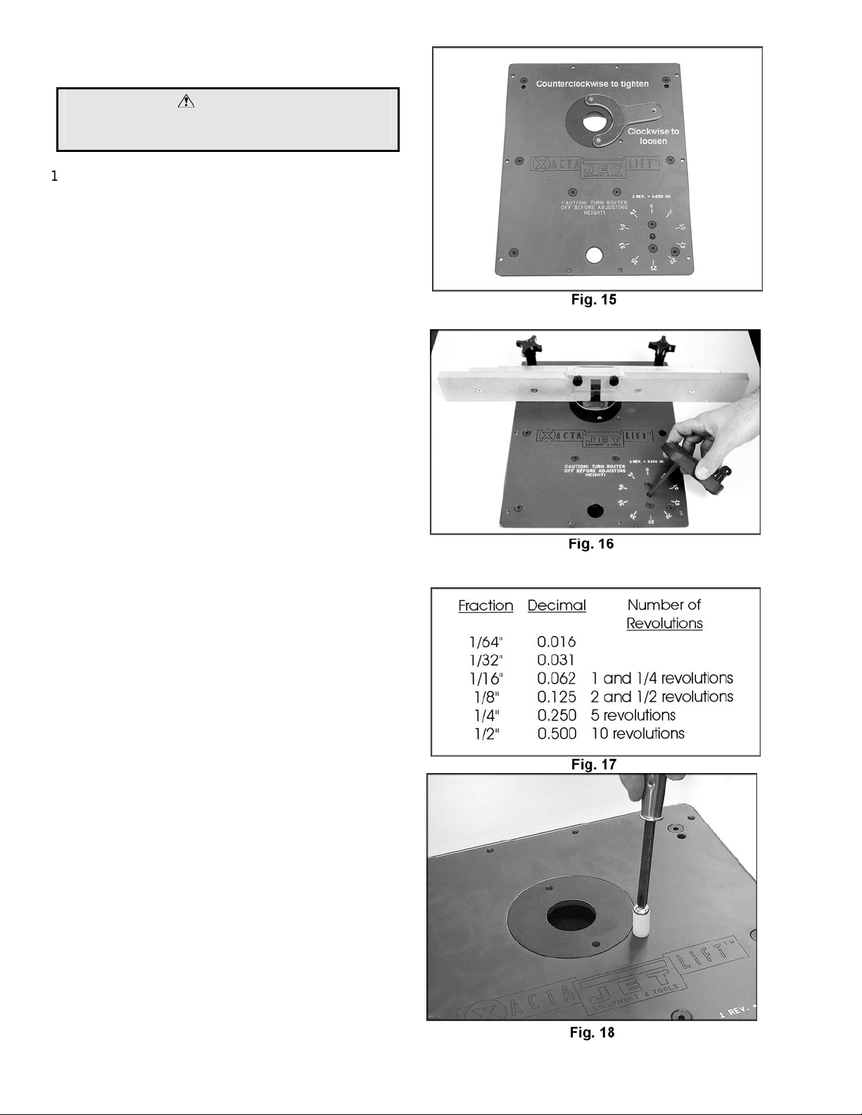
1. Depending on the size of the router bit you are
using it may be desirable to use an i nsert ring to
reduce the size of the opening. To install the insert
ring place the insert int o the opening of t he main
plate, t hen wi th the insert wrench turn
counterclockwise to tighten (then remove the insert
wrench). See Fi g. 15.
2. With the router bit installed, place t he adjustment
handle into ac cess port in the main plate (Fig. 16).
3. Bring the bit flush to the table top.
4. To raise your router, turn the adjustment handl e
clockwise; t o lower turn the adjustment handle
counterclockwise. Keep in mind that one complete
revolution of the adjustm ent handle equals 0.050"
or 1/20". See Fig. 17.
5. Make the desired height adjustment. W hen y our
adjustment is complet e, remove the adjustabl e
handle.
6. A starting pin is prov ided to assist in cert ain
freehand operat ions when the fence is not used.
Thread the pin into the router plate with a
screwdriver (Fig. 18).
8
Page 9

MODIFICATION FOR HEIGHT
ADJUSTMENT TENSION
WARNING
Disconnet router from power source!
The height adjustment tensi on is set at the factory;
however, if you find the tension is too loose and the
router's height adjustment moves when routing, then
modification is as follows:
1. Turn your XACTA LIFT upside down on a table
(Fig. 19).
2. With a 7/16 open end wrench, l oosen the 1/4-20
hex nut (F ig. 20). Then bac k out the antibacklash set scew with the 5/32 hex wrench.
3. Rotate the brass tensioning collar so it tightens
against the rubber washer (Fig. 21). NOTE : A
drop of oi l on the rubber washer eases the
rotation of the brass ring agai nst the washer.
4. Make certain when you have f inished tightening
the coll ar that one of the slots on the coll ar is
centered to the c arriage nut. T his ensures that
the anti-backlash screw will tighten into the slot
of the brass tensioning collar. See Fig. 21.
5. Tighten t he 1/4-20 hex nut (that you loosened in
step 2).
9
Page 10
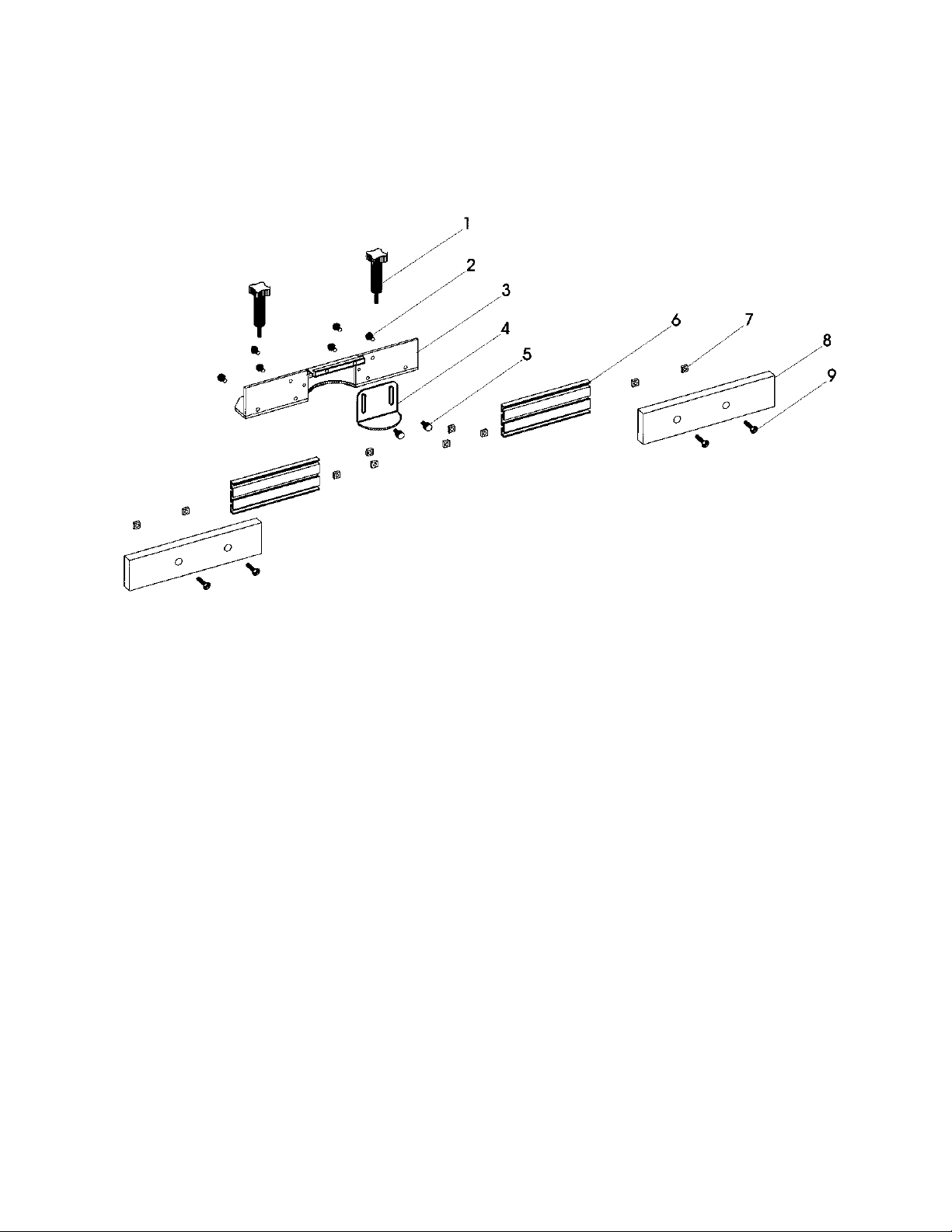
PARTS LIST
XACTA LIFT DELUXE FENCE ASSEMBLY
Index Part
No. No. Description Size Qty.
1 ......... XLIFT-M0026................Fence Clamping Knobs...................... ................................................ 2
2 ......... XLIFT-E0040................Button Head Screw............................1/4-20 x 1/2"............................ 6
3 ......... XLIFT-E0032................Aluminum Fence Bracket...................2-1/2" x 2-1/2" x 3/16" x 14"..... 1
4 ......... XLIFT-M0039................ Fence Guard ...................................... 1/8 Polycarbonate.................... 1
5 ......... XLIFT-M0028................ Guard Clamping Knob........................ ................................................ 2
6 ......... XLIFT-E0030................Aluminum Fence Extension................7/16" x 2-1/2" x 7"....................2
7 ......... XLIFT-F0028................ Square Nut......................................... 1/4-20.................................... 10
8 ......... XLIFT-M0040................ MDF Sub Fences...............................3/4" x 2-1/2" x 10-3/4" .............. 2
9 ......... XLIFT-F0017 ................ Fl at Head Screws............................... 1/4-20 x 1"............................... 4
The specifications i n this manual ar e given as general information and are not binding. JET , WM H Tool Group
reserves the r ight to ef fect, at any time and wit hout prior noti ce, changes or alterat ions to parts,
fittings, and accessory equipment deemed necessary for any reason whatsoever.
10
Page 11

PARTS BREAKDOWN
JET XACTA LIFT
11
Page 12

PARTS LIST
JET XACTA LIFT
Index Part
No. No. Description Size Qty.
1 ......... XLIFT-F0001 ................ Fl at Head Cap Screw ..............................1/4 x 3/4............................ 20
2 ......... XLIFT-P0003-1.............Aluminum Main Plate..............................14-3/4 x 11-3/4 x 1/4........... 1
3 ......... XLIFT-S0001-1.............Steel Side Supports ................................1/2 x 1/2 x 13-1/4................2
4 ......... XLIFT-E0001-1.............Aluminum Shaft Mounting B lock .............1 x 1-1/2 x 10.1 ................... 1
5 ......... XLIFT-F0002 ................ Socket Head Cap Screw .........................1-1/4 x 7/8...........................4
6 ......... XLIFT-M0001................ Steel Drive Pulley Spindle....................... ........................................... 1
7 ......... XLIFT-M0006................ Bronze Flange Bearing ............................3/4 x 7/8 x 3/4.....................1
8 ......... XLIFT-E0001-2.............Drive Pulley Mounting Bl ock ...................1 x 1-1/2 x 2........................ 1
9 ......... XLIFT-M0011................ Rubber T iming B elt.................................130 XL x 3/8........................ 1
10 ....... XLIFT-M0005................Drive Pulley (Delrin)................................20 XL x 3/8..........................1
11 ....... XLIFT-M0009................Bronze Sleeve Bearing...........................3/4 x 7/8 x 3/4..................... 4
12 ....... XLIFT-F0005................Flat Head Cap Screw..............................1/4 x 1................................. 4
13 ....... XLIFT-E0001-3.............Aluminum Bearing Mounts......................1 x 1-1/2 x 4........................ 2
14 ....... XLIFT-S0002-1.............Steel Carriage Nut...................................3/4 x 1 x 1-1/2..................... 1
15 ....... XLIFT-F0003................Nylon Insert Lock Nut..............................1/2-20................................. 1
16 ....... XLIFT-E0002-1.............Aluminum Carriage Bracket ....................3/8 x 3 x 8-1/2..................... 1
17 ....... XLIFT-F0006................Half Dog Pt. Set Screw (Anti-Backlash)...1/4-20 x 1............................1
18 ....... XLIFT-M0012................Rubber W asher.......................................1/2 x 1-1/16 x .093.............. 1
19 ....... XLIFT-M0003................Brass Anti-Backlash Nut..........................1 x .450 x 1/2-20................. 1
20 ....... XLIFT-M0004................Threaded Pulley (Delrin) .........................20 XL w/ 1/2-20................... 1
21 ....... XLIFT-F0004................Socket Head Cap S c r ew .........................1/4 x 1................................. 4
22 ....... XLIFT-S0001-2.............Carriage Mounting Block.........................1/2 x 1/2 x 3 Steel............... 2
23 ....... XLIFT-E0002-2.............Aluminum Carriage Gusset .....................3/8 x 2-1/2 x 3..................... 2
24 ....... XLIFT-P0002................Aluminum Carriage Plate........................7.9 x 8-1/2 x 3/16................ 1
25 ....... XLIFT-M0007................Bronze Thrust Washer............................9/16 x 1-1/4 x 1/16 thk ........ 1
26 ....... XLIFT-M0042................Carriage Lead Screw............................... ........................................... 1
27 ....... XLIFT-M0008................Bronze Flange Bearing............................1/2 x 5/8 x 3/4 Lg................ 1
28 ....... XLIFT-M0017-1............Phenolic Insert Ring................................1-1/2 hole opening .............. 1
29 ....... XLIFT-M0016-1............Insert Wrench ......................................... ........................................... 1
30 ....... XLIFT-M0018................Lift Handle (Arbor on)............................... ........................................... 1
31 ....... XLIFT-M0015................Hex Key..................................................1/4 ...................................... 1
32 ....... XLIFT-F0007................Socket Head Cap S c r ew .........................1/4 x 1-1/4...........................1
33 ....... XLIFT-M0041-1............Phenolic Lif t Handle Knob.......................1/4" Cored Hol e................... 1
34 ....... XLIFT-P0009................Master Ring............................................. ........................................... 1
35 ....... XLIFT-P0011................Master Ring Clamp ................................. ........................................... 6
36 ....... XLIFT-F0008................Oval Point Socket Set Screw..................1/4-28 x 1/4....................... 10
37 ....... XLIFT-P0012................Starter Pin............................................... ........................................... 1
12
Page 13

ROUTER HOLE PATTERNS
The following is a series of hole patterns f or varous routers as noted i n S tep 5 of "Mounting Your Router." Loc ate the
name and correc t model number of your r outer and then locate the holes in the m ast er r ing. With a f elt tip marker or
pencil mark a li ne on the mounting plate for eac h hole you will be using for your router.
13
Page 14

ROUTER HOLE PATTERNS (continued)
14
 Loading...