

Page 1

Operating Instructions and Parts Manual
45-inch English Wheel
Model: WH-45T
JET
427 New Sanford Road
LaVergne, Tennessee 30786 Part No. M-756151
Ph.: 800-274-6848 Revision C1 08/2018
www.jettools.com Copyright © 2017 JET
Page 2

1.0 IMPORTANT SAFETY
INSTRUCTIONS
WARNING – To reduce risk of injury:
1. Read and understand the entire owner’s
manual before attempting assembly or
operation.
2. Read and understand the warnings posted
on the machine and in this manual. Failure
to comply with all of these warnings may
cause serious injury.
3. Replace warning labels if they become
obscured or removed.
4. This English whee l is d es ig ned a nd intended
for use by properl y trained and experience d
personnel only. If you are not familiar with
the proper and safe operat ion of an English
wheel, do not use until proper training and
knowledge have been obtained.
5. Do not use this English wheel for other t han
its intended use. If used f or other purposes,
JET disclaims any real or implied warranty
and holds itself harmless from any injury that
may result from that use.
6. Always wear approved safety glasses/face
shields while using this English wheel.
Everyday eyeglasses only have impact
resistant lenses; they are not safety glasses.
7. Before operating this Engli sh wheel, rem ove
tie, rings, watches an d oth e r j ewelry, and roll
sleeves up past the elbows. Remove all
loose clothing and confine long hair. Nonslip footwear or anti-skid floor strips are
recommended.
8. Use steel-toed footwear when handling
metal workpieces.
9. Do not operate this machine while tired or
under the influence of dr ugs, alcohol or any
medication.
10. Remove adjusting ke ys an d wrench es . F orm
a habit of checking to see that keys and
adjusting wrenches are removed from the
machine before using.
11. Keep safety guards in place at all times
when the machine is in us e. If removed for
maintenance purposes , use extrem e caution
and replace the guards immediately.
12. If possible, the English Wheel should be
secured to the floor before use.
13. Check damaged par ts. Before fur ther use of
the machine, a guard or other part that is
damaged should be carefully checked to
determine that it will operate properly and
perform its intended function. Check for
alignment of moving parts, binding of
moving parts, breakage of parts, mounting
and any other conditions that may affect its
operation. A guard or other part that is
damaged should be properly repaired or
replaced.
14. Provide for adequate space surrounding
work area and non-glare, overhead lighting.
15. Keep the floor around the machine clean
and free of scrap material, oil and grease.
16. Keep visitors a safe distance from the work
area. Keep children away.
17. Make your workshop child proof with
padlocks, master switches or by removing
starter keys.
18. G ive your work undivided atten tion. Looking
around, carrying on a conversation and
“horse-play” are car e les s a c ts that c an res u lt
in serious injury.
19. Do not overreach. Keep proper footing and
balance at all times.
20. Use the r ight too l at th e c orrec t f eed r ate. Do
not force a tool or attachm ent to do a job f or
which it was not designed. The right tool will
do the job better and more safely.
21. Use recommended accessories; improper
accessories may be hazardous.
22. Maintain tools with car e. Keep wheels clean
for best perform ance. Follow instructions for
lubricating and changing accessories.
23. Use leather gloves when handling steel work
pieces.
24. Do not stand on the m achine. Serious injury
could occur if the machine tips over.
25. Rem ove loose items and unnecessar y work
pieces from the area before using the
machine.
WARNING: This product can expose you
to chemicals including lead which is known to
the State of California to cause cancer and
birth defects or o ther reproductive harm . For
more information go to http://www.
p65warnings.ca. gov.
2
Page 3

WARNING: Some dust, fumes and gases
created by power sanding, sawing, grinding,
drilling, welding and other construction
activities contain chemicals known to the
State of California to c ause cancer and birth
defects or other reproductive harm. Some
examples of these chemicals are:
• lead from lead based paint
• crystalline silica from bricks, cement and
other masonry products
• arsenic and chromium from chemically
treated lumber
Your risk of exposure varies, depending on
how often you do this type of work. To
reduce your exposure to these chemicals,
work in a well-ventilated ar ea and work with
approved safety equipment, such as dust
masks that are spec ifically designed to filter
out microscopic particles. For more
information go to http:// www.p65warn ings.ca.
gov/ and http:// www.p65warnings.ca.gov/
wood.
Familiarize yourself with the following safety
notices used in this manual:
This means that if precautions
are not heeded, it may result in minor injury
and/or possible machine damage.
This means that if precautions
are not heeded, it m ay result in serious injury or
possibly even death.
SAVE THESE INSTRUCTIONS
2.0 Table of Contents
1.0 IMPORTANT SAFETY INSTRUCTIONS ............................................................................................... 2
2.0 Table of Contents ................................................................................................................................... 3
3.0 About this manual .................................................................................................................................. 4
4.0 Specifications ......................................................................................................................................... 4
5.0 Setup and assembly ............................................................................................................................... 5
5.1 Shipping contents ............................................................................................................................... 5
5.2 Tools required for assembly ............................................................................................................... 5
5.3 Unpacking and cleanup ...................................................................................................................... 5
5.4 Location .............................................................................................................................................. 5
5.5 Mobility ............................................................................................................................................... 5
6.0 Adjustments ........................................................................................................................................... 5
6.1 Installing wheels ................................................................................................................................. 5
6.2 Wheel orientation................................................................................................................................ 6
6.3 Wheel alignment ................................................................................................................................. 6
7.0 Operation ............................................................................................................................................... 7
8.0 User-maintenance .................................................................................................................................. 7
8.1 Lubrication .......................................................................................................................................... 7
8.2 Additional servicing............................................................................................................................. 7
9.0 Troubleshooting WH-45T English Wheel ............................................................................................... 8
10.0 Replacement Parts ............................................................................................................................... 8
10.1 WH-45T English Wheel – Exploded View ........................................................................................ 9
10.2 WH-45T English Wheel – Parts List ............................................................................................... 10
11.0 Wheel Chart ....................................................................................................................................... 12
12.0 Warranty and Service......................................................................................................................... 13
The specifications in t his m anual are gi ven as gener al inf ormation and ar e not bin ding. JET reserves the
right to effect, at any time and wit hout prior not ice, changes or alterati ons to parts, fittings, and acc essor y
equipment deemed necessary for any reason whatsoever.
3
Page 4

3.0 About this manual
This manual is pro vided by JET, covering the saf e operation and maintenance procedures for the JET
WH-45T English Wheel. This manual contains instructions on installation, safety precautions, general
operating procedures , maintenance instruc tions and parts breakdown. T his machine has been d esigned
and constructed to provide consistent, long-term operation if used in accordance with instructions set
forth in this manual. If there are any questions or comments, please cont act either your loca l supplier or
JET. JET can also be reached at our web site: www.jettools.com.
If there are questions or comments, please contact your local supplier or JET. JET can also be reached at
our web site: www.jettools.com.
Retain this manual for future reference. If the machine transfers ownership, the manual should
accompany it.
Read and understand the entire contents of this manual before attempting
assembly or operation! Failure to comply may cause serious injury!
Register your product using the mail-in card provided, or register online:
http://www.jettools.com/us/en/service-and-support/warranty/registration/
4.0 Specifications
Model .................................................................................................................................................. WH-45T
Stock Number ..................................................................................................................................... 756151
Number of lower wheels provided ............................................................................................................... 10
Number of upper wheels provided ................................................................................................................ 4
Construction:
Frame ................................................................................. 4-3/4" square, 7-gauge gusseted steel tubing
Wheels ............................................................................................................................... hardened steel
Number of lower wheel stor age holder s ................................................................................................ 10
Number of upper wheel storage hol ders .................................................................................................. 3
Capacities:
Mild Steel ....................................................................................................................... 16 Gauge (0.06")
Aluminum ............................................................................................................................................. 1/8"
Copper............................................................................................................................ 16 Gauge (0.05")
Dimensions:
Throat .................................................................................................................................................... 45"
Adjustment Post Diameter .............................................................................................................. 2-7/16"
Footprint ....................................................................................................................................... 59" x 28"
Overall Dimensions, shipped .....................................................................................67"L x 59" W x 15"H
Overall Dimensions, assembled ................................................................................56"L x 28" W x 63"H
Weights:
Shipping ........................................................................................................................................ 555 lbs.
Net ................................................................................................................................................. 458 lbs.
The specifications in t his m anual are gi ven as gener al inf ormation and ar e not bin ding. JET reserves the
right to effect, at any time and wit hout prior not ice, changes or alterati ons to parts, fittings, and acc essor y
equipment deemed necessary for any reason whatsoever.
4
Page 5

Read and understand all
assembly instructions before attempting
assembly. Use an assist ant when any heavy
lifting is required. Failure to comply may
cause serious injury.
5.0 Setup and assembly
5.1 Shipping contents
1 English wheel
10 Lower wheel assemblies
4 Upper wheel assemblies
1 Operating instructions and par ts m anual
1 Product registration card
5.2 Tools required for assembly
8mm hex key (provided)
21 and 24mm (or adjustable) wrench
5.3 Unpacking and cleanup
1. Inspect contents for shipping damage.
Report damage, if any, to your distributor.
Do not discard shipping materials until
machine is installed and running properly.
2. Compare contents of shipping carton with
the contents list in this manual. Report
shortages, if any, to your distributor.
3. Remove rust protectant from exposed
surfaces, such as shafts and post, with a
clean rag and a cleaner/degreaser or
kerosene. Apply a light coat of oil on these
surfaces to inhibit rust. D o not use gasoline,
acetone, or lacquer thinner as these will
damage painted surfaces. Do not use an
abrasive pad, as it may scratch finished
surfaces.
Figure 5-1
6.0 Adjustments
6.1 Installing wheels
The JET English W heel is prov ided with 4 upper
wheels and 10 lower wheels. Their distinct
profiles are shown in sect. 13.0. Wipe off any
excess oil residue from wheels before operating.
6.1.1 Upper wheel
1. Rotate position block (A, Figure 6-1) to
release shaft.
2. Securely hold upper wheel (B) with one
hand, and slide out upper wheel shaft (C).
Set upper wheel in storage bracket on
frame.
3. Reverse above procedure to install new
upper wheel. Make sure pos ition b lock (A) is
re-engaged to secure shaft.
5.4 Location
Locate the machine on a solid, level floor,
preferably concrete. Area should have good
overhead lighting and ventilation, with enough
room for loading and offloading of stock and
general maintenance. Although the English
Wheel is mobile it is recommended that, once
positioned, it be secured to floor using lag
screws (not provided) or similar means through
provided holes in base.
5.5 Mobility
Retractable casters beneath main column and
support legs allow m achine to be m oved by one
person. Rotate the s quare head bolts ( Figure 5-
1) with a wrench to lower or raise casters.
NOTE: Always retract casters before operating
machine.
5
Figure 6-1
Page 6
6.1.2 Lower wheel
1. Release cam lever (D, Figure 6-1) and
remove lower wheel (E). If needed, use
adjusting wheel (see F , Figure 8-1) to lower
post further for additional clearance.
2. Position new wheel in groove and engage
cam lever.
3. Raise lower wheel assembly using adjusting
wheel (F, Figure 8-1).
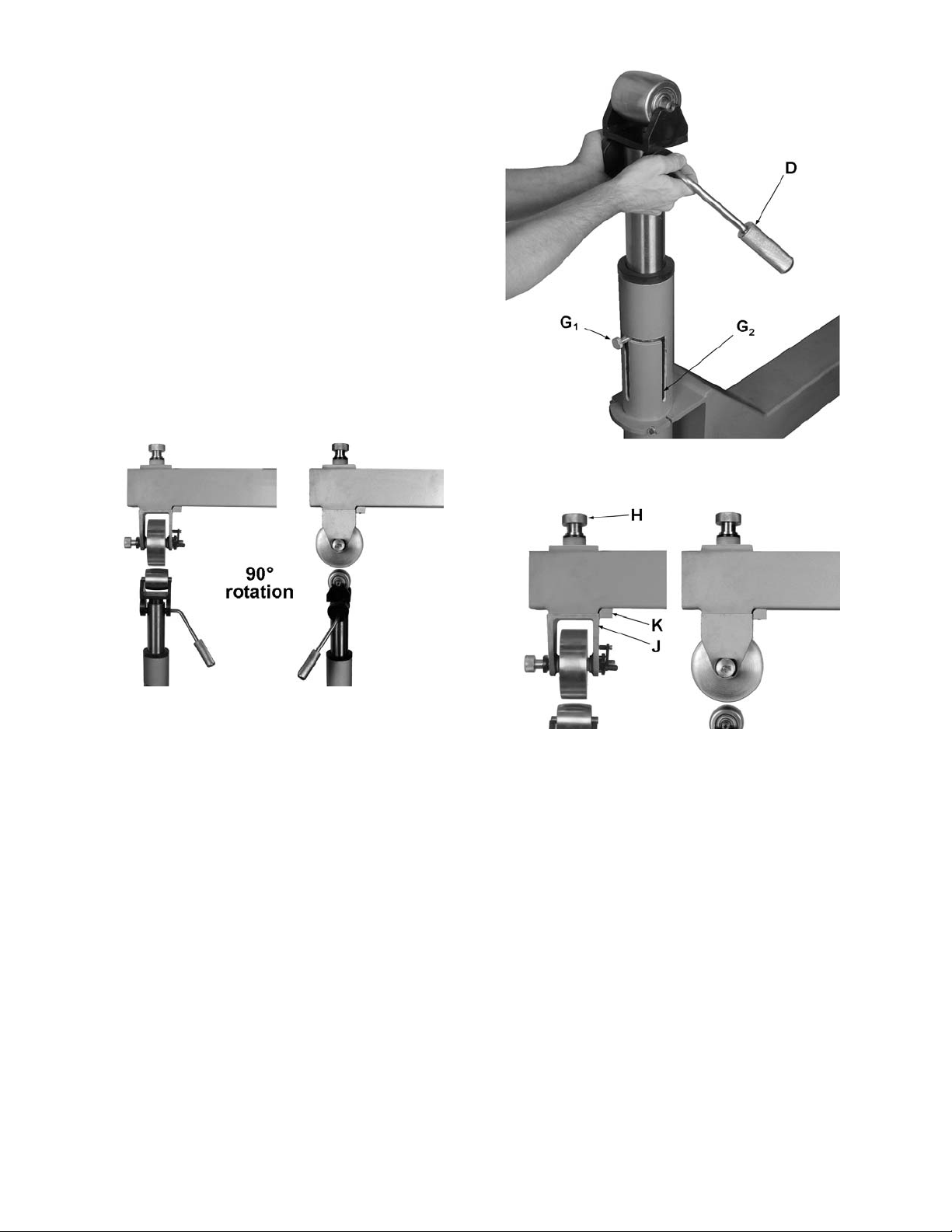
6.2 Wheel orientation
Upper and lower wheel housings can be r otated
90-degrees to accommodate different sizes of
material, and prevent material from contacting
machine frame while bein g worked. See Figure
6-2.
Remove lower wheel to provide clearance for
the following steps.
Figure 6-3
Figure 6-2
6.2.1 Lower wheel positioning
1. Release cam lever (D, Figure 6-3).
2. Raise lower wheel housing until knurled
screw (G
) reaches top of slot, as shown.
1
3. Turn lower wheel housing until knurled
screw enters opposite slot, and push down
until knurled screw hits bottom of opposite
slot (G
).
2
6.2.2 Upper wheel positioning
1. Turn adjustment knob (H, Figure 6-4)
counterclockwise until upper wheel housin g
(J) clears frame block (K).
2. Turn upper wheel ho using 90-degrees, and
raise it by turning adjustment knob (H)
clockwise until housing is properly seated.
3. Install lower wheel and bring lower wheel
assembly into working pos it ion.
Figure 6-4
6.3 Wheel alignment
If wheels are not centered with one another,
alignment can be made as follows.
1. Loosen four set screws (L, Figure 6-5).
2. Turn adjusting nut (M) outward (counterclockwise) in small incremental steps, and
the opposite adjusting nut inward by the
same amount, until upper whee l is centered
over lower wheel.
3. Tighten four setscrews (L).
6
Page 7
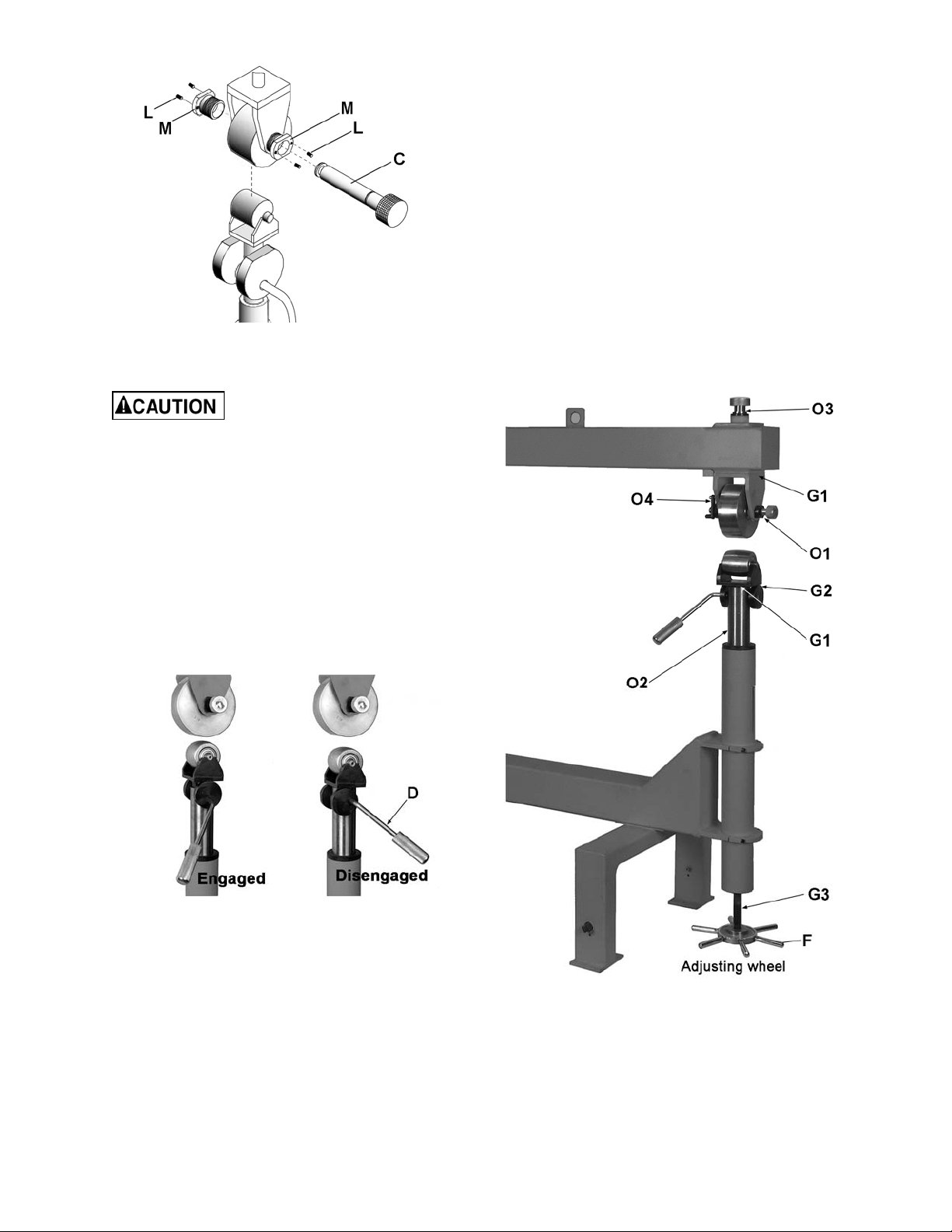
7. To remove and re-insert same-gauge
material, simply engage or disengage cam
lever.
8.0 User-maintenance
8.1 Lubrication
Refer to Figure 8-1.
Periodically appl y grease to contact surfaces of
upper and lower wheel housings (G1), cams
(G2), and adjusting wheel leadscrew (G3).
Figure 6-5
7.0 Operation
Wear work gloves when
handling sheet metal. Keep hands away from
wheel contact area during operation.
1. Deburr any sharp edges in work material,
and ensure that material and wheels are
clean and free of obstructions. Make sure
material is within working capacity of
machine. See sect. 4.0.
2. Make sure upper wheel housing is secure
against frame, and both wheels are rotated
to proper orientation for work piece.
3. Tighten cam lever (D, Figure 7-1) to bring
lower wheel into work ing pos ition.
Periodically apply a light machine oil to upper
wheel shaft (O1), lower wheel post (O2),
adjusting nut (O3), an d position b lock pivot area
(O4). Also appl y l igh t coa t of oil to whee ls bef or e
storing them, to inhibit rust.
Figure 7-1
4. Rest material on lower wheel, and use
adjusting wheel (F, Figure 8-1) to bring
material into contact with u pper wheel. Note :
Do not use excessive pressure; use lightes t
pressure necessary to obtain desired result.
5. Move material back and forth to shape it.
6. Rotate adjusting wheel (F, Figure 8-1) as
needed during op eration to maintain proper
pressure.
Figure 8-1
8.2 Additional servicing
Any additional ser vicing s hould be performed b y
authorized service personnel.
7
Page 8

9.0 Troubleshooting WH-45T English Wheel
Table 1
Trouble Probable Cause Remedy
Pressing workpiece too lightly. Raise lower wheel for better contact.
Material not being
shaped by wheels.
Roll marks or
marring of material.
Upper wheel
housing does not
seat properly, or
shifts during use.
Material has waves
instead of smooth
curve.
Edge of material
uneven or
stretched.
Improper crown
being formed in
material.
Improper wheel selection. Use proper wheel combination. Make
sure lower wheel has appropriate
crown.
Sheet metal too thick. Select material within machine
capacity.
Pressure too tight against workpiece. Use minimal pressure of wheels
against workpiece.
Wheel housing not straight with frame
block.
Material unevenly stretched, not
being moved properly throu gh
wheels.
Edges of material being run through
wheels.
Too much crown: Contact surface on
lower wheel is too sm all.
Not enough crown: Contact surface
on lower wheel is too large.
Adjust housing while tightening knob,
until housing clears block and seats
properly against fram e.
Feed material evenly back and forth in
parallel motions, do not zigzag across
workpiece.
Avoid moving edge of material through
wheels.
Use different lower wheel with larger
flat surface.
Use different lower wheel with smaller
flat surface.
Cam lever works
improperly or feels
loose.
Parts are binding. Lubricate cam/housing contact areas.
Set screws loose. Tighten set screws. Make sure they
align with flats on cam lever shaft.
Table 1
10.0 Replacement Parts
Replacement parts are lis ted on the fol lowing pag es. To order parts or reach our service de partm ent, call
1-800-274-6848 Monday through Friday, 8:00 a.m. to 5:00 p.m. CST. Having the Model Number and
Serial Number of your machine available when you call will allow us to serve you quickly and accurately.
Non-proprietary parts , such as fas teners, can be foun d at local hard ware stores, or may be ordered f rom
JET. Some parts are shown for reference only, and may not be available individually.
8
Page 9
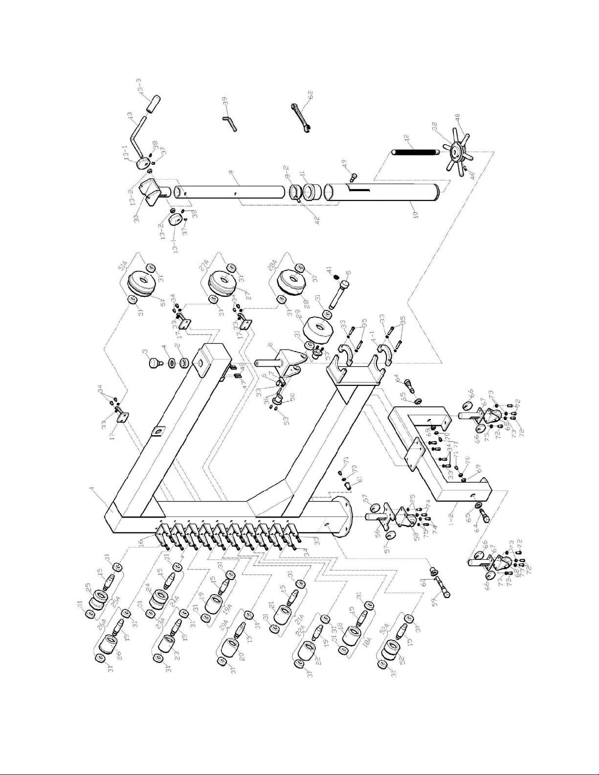
10.1 WH-45T English Wheel – Exploded View
9
Page 10

10.2 WH-45T English Wheel – Parts List
Index No. Part No. Description Size Qty
1 ............... WH45T-1G ............... Frame ................................................................... .................................... 1
1-1 ............ WH45T-1-1G ............ Post Clamp........................................................... .................................... 2
1-2 ............ WH45T-1-2G ............ Frame Support Stand ........................................... .................................... 1
2 ............... WH45-2 .................... Collar .................................................................... .................................... 1
3 ............... WH45-3 .................... Adjusting Lock Knob ............................................ .................................... 1
4 ............... WH45-4 .................... Washer ................................................................. .................................... 1
5 ............... WH45-5 .................... Upper Wheel Shaft ............................................... .................................... 1
6 ............... WH45-6 .................... Short Pin .............................................................. .................................... 1
7 ............... WH45-7 .................... Position Block....................................................... .................................... 1
8 ............... WH45-8G ................. Upper Wheel Housing .......................................... .................................... 1
9 ............... WH45-9 .................... Inner Tube Adjusting Post .................................... .................................... 1
9-2 ............ WH45-9-2 ................. Collar .................................................................... .................................... 1
10 ............. WH45-10G ............... Outer Post ............................................................ .................................... 1
11 ............. WH45-11 .................. Flange Bushing .................................................... .................................... 1
12 ............. WH45-12 .................. Lead Screw .......................................................... .................................... 1
13 ............. WH45-13 .................. Lifting Lever.......................................................... .................................... 1
13-1 .......... WH45-13-1 ............... Cam ...................................................................... .................................... 2
13-2 .......... WH45-13-2 ............... Spacer .................................................................. .................................... 2
13-3 .......... WH45-13-3 ............... Lifting Lever Handle ............................................. .................................... 1
15 ............. WH45-15 .................. Lower Wheel Shaft ............................................... .................................. 10
16 ............. WH45-16G ............... Lower Wheel Storage Bracket ............................. .................................. 10
17 ............. WH45-17 .................. Upper Wheel Storage Bracket ............................. .................................... 3
18A ........... WH45-18A ............... Lower Wheel 1 Assembly (Index #18, 15, 31) ..... 1/8” Edge .................... 1
18 ............. WH45-18 .................. Lower Wheel 1 ..................................................... .................................... 1
19A ........... WH45-19A ............... Lower Wheel 9 Assembly (Index #19, 15, 31) ..... 1/2" Ridged ................. 1
19 ............. WH45-19 .................. Lower Wheel 9 ..................................................... .................................... 1
20A ........... WH45-20A ............... Lower Wheel 7 Assembly (Index #20, 15, 31) ..... 1/8" Ridged ................. 1
20 ............. WH45-20 .................. Lower Wheel 7 ..................................................... .................................... 1
21A ........... WH45-21A ............... Lower Wheel 6 Assembly (Index #21, 15, 31) ..... 1/4" .............................. 1
21 ............. WH45-21 .................. Lower Wheel 6 ..................................................... .................................... 1
22A ........... WH45-22A ............... Lower Wheel 8 Assembly (Index #22, 15, 31) ..... 3/4" .............................. 1
22 ............. WH45-22 .................. Lower Wheel 8 ..................................................... .................................... 1
23A ........... WH45-23A ............... Lower Wheel 4 Assembly (Index #23, 15, 31) ..... 2-1/4”........................... 1
23 ............. WH45-23 .................. Lower Wheel 4 ..................................................... .................................... 1
24A ........... WH45-24A ............... Lower Wheel 3 Assembly (Index #24, 15, 31) ..... 3/4" .............................. 1
24 ............. WH45-24 .................. Lower Wheel 3 ..................................................... .................................... 1
25A ........... WH45-25A ............... Lower Wheel 2 Assembly (Index #25, 15, 31) ..... 1-29/64”....................... 1
25 ............. WH45-25 .................. Lower Wheel 2 ..................................................... .................................... 1
26A ........... WH45-26A ............... Lower Wheel 5 Assembly (Index #26, 15, 31) ..... 2-5/8" .......................... 1
26 ............. WH45-26 .................. Lower Wheel 5 ..................................................... .................................... 1
27A ........... WH45-27A ............... Upper Wheel 10 Assembly (Index #27, 31) ......... 3/4" .............................. 1
27 ............. WH45-27 .................. Upper Wheel 10 ................................................... .................................... 1
28A ........... WH45-28A ............... Upper Wheel 11 Assembly (Index #28, 31) ......... 1-29/64”....................... 1
28 ............. WH45-28 .................. Upper Wheel 11 ................................................... .................................... 1
29A ........... WH45-29A ............... Upper Wheel 12 Assembly (Index #29, 31) ......... 1/8” Edge .................... 1
29 ............. WH45-29 .................. Upper Wheel 12 ................................................... .................................... 1
30 ............. WH45-30 .................. Lower Wheel Housing .......................................... .................................... 1
31 ............. BB-6204ZZ ............... Ball Bearing .......................................................... 6204ZZ...................... 28
32 ............. WH45-32 .................. Adjusting Wheel ................................................... .................................... 1
33 ............. TS-1551041 ............. Lock Washer ........................................................ M6 ............................. 35
34 ............. T S-150306 1 ............. Socket Head Cap Scre w ...................................... M6x25 ....................... 30
35 ............. T S-150311 1 ............. Socket Head Cap Scre w ...................................... M6x50 ......................... 4
36 ............. T S-150309 1 ............. Socket Head Cap Scre w ...................................... M6x40 ......................... 1
37 ............. TS-1522031 ............. Socket Set Screw ................................................. M5x10 ......................... 2
38 ............. TS-1522041 ............. Socket Set Screw ................................................. M5x12 ......................... 2
39 ............. TS-152706 ............... Hex Wrench ......................................................... 5mm ............................ 1
40 ............. WH45-40 .................. Wheel Handle....................................................... .................................... 6
10
Page 11

Index No. Part No. Description Size Qty
41 ............. WH45-41 .................. Snap Ring ............................................................ Ø20 ............................. 1
42 ............. TS-1522031 ............. Socket Set Screw ................................................. M5x10 ......................... 1
46 ............. TS-1523021 ............. Socket Set Screw ................................................. M6x8 ........................... 1
47 ............. T S-150307 1 ............. Socket Head Cap Scre w ...................................... M6x30 ......................... 2
48 ............. WH45-48 .................. Spring Pin............................................................. Ø5x30 ......................... 2
49 ............. WH45-49 .................. Adjusting Lock Bolt .............................................. .................................... 1
50 ............. WH45-50 .................. Adjusting Nut ........................................................ .................................... 2
51A ........... WH45-51A ............... Upper Wheel 13 Assembly (Index #51, 31) ......... 1/4" .............................. 1
51 ............. WH45-51 .................. Upper Wheel 13 ................................................... .................................... 1
52A ........... WH45-52A ............... Lower Wheel 14 Assembly (Index #52, 15, 31) ... 1/4" .............................. 1
52 ............. WH45-52 .................. Lower Wheel 14 ................................................... .................................... 1
53 ............. TS-1523061 ............. Socket Set Screw ................................................. M6x20 ......................... 4
56 ............. WH45T-56 ................ Rear Caster Post ................................................. .................................... 1
57 ............. WH45T-57 ................ Rear Eccentric Wheel .......................................... .................................... 2
58 ............. WH45T-58 ................ Rear Caster .......................................................... Ø70 mm ...................... 1
59 ............. WH45T-59 ................ Rear Eccentric Wheel Shaft ................................. .................................... 1
60 ............. WH45T-60 ................ Rear Bushing Shaft .............................................. .................................... 1
61 ............. WH45T-61 ................ Bushing ................................................................ .......... .......................... 1
62 ............. WH45T-62 ................ Open End Wrench ............................................... 18 mm ......................... 1
64 ............. WH45T-64 ................ Front Eccentric Wheel Shaft ................................ .................................... 2
65 ............. WH45T-65 ................ Front Bushing Shaft ............................................. .................................... 2
66 ............. WH45T-66 ................ Front Eccentric Wheel .......................................... .................................... 4
67 ............. WH45T-67 ................ Front Caster Post ................................................. .................................... 2
68 ............. WH45T-68 ................ Front Caster ......................................................... Ø70 mm ...................... 2
69 ............. WH45T-69 ................ Shaft Bushing ....................................................... .................................... 2
70 ............. WH45T-70 ................ Snap Ring ............................................................ .................................... 3
71 ............. T S-150304 1 ............. Socket Head Cap Scre w ...................................... M6x15 ......................... 3
72 ............. TS-1482041 ............. Hex Cap Screw .................................................... M6x20 ......................... 8
73 ............. TS-1550041 ............. Flat Washer .......................................................... M6 ............................... 8
74 ............. T S-150405 1 ............. Socket Head Cap Scre w ...................................... M8x25 ......................... 4
75 ............. TS-1550041 ............. Flat Washer .......................................................... M6 ............................... 4
................. LM000158 ................ ID Label, WH-45T (not shown) ............................ .................................... 1
................. JET-165 ................... JET Logo (not shown) .......................................... 165 x 68mm ................ 1
Note: Upper and Lower Wheels can only be purchased as an assembly.
11
Page 12

11.0 Wheel Chart
Index No. Wheel Description Spec
Index No. Wheel Description Spec
18
19
20
21
22
23
24
Lower wheel 1 1/8" Edge Lower wheel 2 1-29/64"
Lower wheel 9 1/2" Ridged Lower wheel 5 2-5/8"
Lower wheel 7 1/8" Ridged Lower wheel 14 1/4"
Lower wheel 6 1/4" Upper wheel 10 3/4"
Lower wheel 8 3/4" Upper wheel 11 1-29/64"
Lower wheel 4 2-1/4" Upper wheel 13 1/4"
Lower wheel 3 3/4" Upper wheel 12 1/8" Edge
25
26
52
27
28
51
29
Table 2
To purchase a particular wheel, select the Index No. from the column to the left of the wheel and use that
number to determine the Part No. in the Parts List (preceding pages). Note that the wheel is sold as an
assembly only that includes the wheel, ball bearings and shaft (lower wheel only). For example, when ordering
Lower Wheel 1 (Index 18), order Part Number WH45-18A (Index 18A) from the Parts List in sect. 12.2.
12
Page 13

12.0 Warranty and Service
JET warrants every product it sells against manufacturers’ defects. If one of our tools needs service or repair, please
contact Technical Service by calling 1-800-274-6846, 8AM to 5PM CST, Monday through Friday.
Warranty Period
The general warranty lasts for the time period specified in the literature included with your product or on the official
JET branded website.
• JET products carry a limited warranty which varies in duration based upon the product. (See chart below)
• Accessories carry a limited warranty of one year from the date of receipt.
• Consumable items are defined as expendable parts or accessories expected to become inoperable within a
reasonable amount of use and are covered by a 90 day limited warranty against manufacturer’s defects.
Who is Covered
This warranty covers only the initial purchaser of the product from the date of delivery.
What is Covered
This warranty covers any defects in workmanship or materials subject to the limitations stated below. This warranty
does not cover failures due directly or indirectly to misuse, abuse, negligence or accidents, normal wear-and-tear,
improper repair, alterations or lack of maintenance. JET woodworking machinery is designed to be used with Wood.
Use of these machines in the processing of metal, plastics, or other materials outside recommended guidelines may
void the warranty. The exceptions are acrylics and other natural items that are made specifically for wood turning.
Warranty Limitations
Woodworking products with a Five Year Warranty that are used for commercial or industrial purposes default to a
Two Year Warranty. Please contact Technical Service at 1-800-274-6846 for further clarification.
How to Get Technical Support
Please contact Technical Service by calling 1-800-274-6846. Please note that you will be asked to provide proof
of initial purchase when calling. If a product requires further inspection, the Technical Service representative will
explain and assist with any additional action needed. JET has Authorized Service Centers located throughout the
United States. For the name of an Authorized Service Center in your area call 1-800-274-6846 or use the Service
Center Locator on the JET website.
More Information
JET is constantly adding new products. For complete, up-to-date product information, check with your local distributor
or visit the JET website.
How State Law Applies
This warranty gives you specific legal rights, subject to applicable state law.
Limitations on This Warranty
JET LIMITS ALL IMPLIED WARRANTIES TO THE PERIOD OF THE LIMITED WARRANTY FOR EACH PRODUCT.
EXCEPT AS STATED HEREIN, ANY IMPLIED WARRANTIES OF MERCHANTABILITY AND FITNESS FOR A
PARTICULAR PURPOSE ARE EXCLUDED. SOME STATES DO NOT ALLOW LIMITATIONS ON HOW LONG AN
IMPLIED WARRANTY LASTS, SO THE ABOVE LIMITATION MAY NOT APPLY TO YOU.
JET SHALL IN NO EVENT BE LIABLE FOR DEATH, INJURIES TO PERSONS OR PROPERTY, OR FOR
INCIDENTAL, CONTINGENT, SPECIAL, OR CONSEQUENTIAL DAMAGES ARISING FROM THE USE OF OUR
PRODUCTS. SOME STATES DO NOT ALLOW THE EXCLUSION OR LIMITATION OF INCIDENTAL OR
CONSEQUENTIAL DAMAGES, SO THE ABOVE LIMITATION OR EXCLUSION MAY NOT APPLY TO YOU.
JET sells through distributors only. The specifications listed in JET printed materials and on official JET website are
given as general information and are not binding. JET reserves the right to effect at any time, without prior notice,
those alterations to parts, fittings, and accessory equipment which they may deem necessary for any reason
whatsoever. JET
Product Listing with Warranty Period
90 Days – Parts; Consumable items
1 Year – Motors; Machine Accessories
2 Year – Metalworking Machinery; Electric Hoists, Electric Hoist Accessories; Woodworking Machinery used
for industrial or commercial purposes
5 Year – Woodworking Machinery
Limited Lifetime – JET Parallel clamps; VOLT Series Electric Hoists; Manual Hoists; Manual Hoist
Accessories; Shop Tools; Warehouse & Dock products; Hand Tools; Air Tools
NOTE: JET is a division of JPW Industries, Inc. References in this document to JET also apply to JPW Industries,
Inc., or any of its successors in interest to the JET brand.
®
branded products are not sold in Canada by JPW Industries, Inc.
13
Page 14

This page intentional ly left bla nk.
14
Page 15

This page intentional ly left bla nk.
15
Page 16

427 New Sanford Road
LaVergne, Tennessee 37086
Phone: 800-274-6848
www.jettools.com
16
 Loading...