

Operating Instructions and Parts Manual
Self-Feed Vertical Band Saw
Models: VSF-14-1 and VSF-14-3
WMH TOOL GROUP
2420 Vantage Drive
Elgin, Illinois 60123
Ph.: 888-594-5866
Fax: 800-626-9676
www.wmhtoolgroup.com
Part No. 5518247
Revision A6 09/03
Copyright WMH Tool Group

This manual has been prepared for the owner and operator of a Model VSF-14 Self-Feed Vertical
Band Saw. Its purpose, aside from machine operation, is to promote safety using accepted
operating and maintenance procedures. To obtain maximum life and efficiency from your band
saw and to aid in using the machine safely, please read this manual thoroughly and follow
instructions carefully.
Warranty and Service
WMH Tool Group warrants every product it sells. If one of our tools needs service or repair, one
of our Authorized Repair Stations located throughout the United States can provide quick service
or information.
In most cases, a WMH Tool Group Repair Station can assist in authorizing repair work, obtaining
replacement parts, or perform routine or major maintenance repair on your JET product.
For the name of an Authorized Repair Station in your area, please call 1-888-594-5866, or visit
our web site at www.wmhtoolgroup.com
More Information
Remember, WMH Tool Group is consistently adding new products to the line. For complete, upto-date product information, check with your local WMH Tool Group distributor, or visit our web
site at www.wmhtoolgroup.com
.
WMH Tool Group Warranty
WMH Tool Group makes every effort to assure that its products meet high quality and durability
standards and warrants to the original retail consumer/purchaser of our products that each
product be free from defects in materials and workmanship as follows: 1 YEAR LIMITED
WARRANTY ON ALL PRODUCTS UNLESS SPECIFIED OTHERWISE, 6 MONTH LIMITED
WARRANTY ON THE MOTOR. This Warranty does not apply to defects due directly or indirectly
to misuse, abuse, negligence or accidents, normal wear-and-tear, repair or alterations outside our
facilities, or to a lack of maintenance.
WMH TOOL GROUP LIMITS ALL IMPLIED WARRANTIES TO THE PERIOD SPECIFIED
ABOVE, BEGINNING FROM THE DATE THE PRODUCT WAS PURCHASED AT RETAIL.
EXCEPT AS STATED HEREIN, ANY IMPLIED WARRANTIES OR MERCHANTABILITY AND
FITNESS ARE EXCLUDED. SOME STATES DO NOT ALLOW LIMITATIONS ON HOW LONG
THE IMPLIED WARRANTY LASTS, SO THE ABOVE LIMITATION MAY NOT APPLY TO YOU.
IN NO EVENT SHALL WMH TOOL GROUP BE LIABLE FOR DEATH, INJURIES TO PERSONS
OR PROPERTY, OR FOR INCIDENTAL, CONTINGENT, SPECIAL, OR CONSEQUENTIAL
DAMAGES ARISING FROM THE USE OF OUR PRODUCTS. SOME STATES DO NOT ALLOW
THE EXCLUSION OR LIMITATION OF INCIDENTAL OR CONSEQUENTIAL DAMAGES, SO
THE ABOVE LIMITATION OR EXCLUSION MAY NOT APPLY TO YOU.
To take advantage of this warranty, the product or part must be returned for examination, postage
prepaid, to an Authorized Repair Station designated by our office. Proof of purchase date and an
explanation of the complaint must accompany the merchandise. If our inspection discloses a
defect, we will either repair or replace the product at our discretion, or refund the purchase price if
we cannot readily and quickly provide a repair or replacement. We will return the 7repaired
product or replacement at WMH Tool Group’s expense, but if it is determined there is no defect,
or that the defect resulted from causes not within the scope of WMH Tool Group’s warranty, then
the user must bear the cost of storing and returning the product. This warranty gives you specific
legal rights; you may also have other rights, which vary from state to state.
WMH Tool Group sells through distributors only. Members of the WMH Tool Group reserve the
right to effect at any time, without prior notice, alterations to parts, fittings, and accessory
equipment, which they may deem necessary for any reason whatsoever.
2

Table of Contents
Warranty and Service .................................................................................................................................................. 2
More Information ..................................................................................................................................................... 2
WMH Tool Group Warranty .................................................................................................................................... 2
Table of Contents ......................................................................................................................................................... 3
Table of Figures ........................................................................................................................................................... 4
Warnings...................................................................................................................................................................... 5
How The VSF-14 Band Saw Operates........................................................................................................................ 7
Introduction .................................................................................................................................................................. 8
Specifications............................................................................................................................................................... 8
Model....................................................................................................................................................................... 8
VSF-14-1 ............................................................................................................................................................ 8
VSF-14-3 ............................................................................................................................................................ 8
Standard Features .................................................................................................................................................. 8
Standard Equipment ............................................................................................................................................... 8
Description ................................................................................................................................................................... 9
Installation.................................................................................................................................................................. 10
General ................................................................................................................................................................. 10
Machine Setup ...................................................................................................................................................... 10
Electrical Connections .......................................................................................................................................... 10
Cleaning ................................................................................................................................................................ 11
Operation ................................................................................................................................................................... 11
General ................................................................................................................................................................. 11
Controls................................................................................................................................................................. 11
Changing blade speeds: ....................................................................................................................................... 12
Blade Selection .......................................................................................................................................................... 12
Blade Removal and Installation ............................................................................................................................ 12
Blade Break-In Procedures................................................................................................................................... 13
Controlling the Cut ..................................................................................................................................................... 13
Hydraulic Feed Control ......................................................................................................................................... 13
Evaluating Cutting Efficiency ................................................................................................................................ 14
Setting the Vise for Angle Cuts ............................................................................................................................. 14
Setting the Vise for Square Cuts........................................................................................................................... 14
Work Setup ................................................................................................................................................................ 14
Setting the Blade Guide Bracket........................................................................................................................... 14
Starting the Saw.................................................................................................................................................... 15
Service and Maintenance .......................................................................................................................................... 16
Adjustments .......................................................................................................................................................... 16
Blade Tracking Adjustments ............................................................................................................................ 16
Blade Guide Bearing Adjustment ..................................................................................................................... 17
Cleaning ................................................................................................................................................................ 18
Lubrication............................................................................................................................................................. 18
Changing the Drive Motor V-Belt .......................................................................................................................... 18
Chip Brush and Chip Scraper Replacement......................................................................................................... 18
Blade Guide Bearing Replacement ...................................................................................................................... 19
Drive Motor Replacement ..................................................................................................................................... 19
Adjusting or Replacing the Counterbalance ......................................................................................................... 19
Replacing the Drive Wheel (Lower Wheel)........................................................................................................... 20
Replacing the Idler Wheel or Bearings (Upper Wheel)......................................................................................... 20
Troubleshooting ......................................................................................................................................................... 21
Replacement Parts .................................................................................................................................................... 23
Parts List for VSF-14 Saw Frame ......................................................................................................................... 25
Parts List for the VSF-14 Base ............................................................................................................................. 29
Parts List for the VSF-14 Gear Box Assembly...................................................................................................... 31
Parts List for the VSF-14 Bearing Shaft Assembly ............................................................................................... 32
Parts List for the VSF-14 Smooth Wheel Assembly ............................................................................................. 33
Parts List for the VSF-14 Idler Wheel Assembly .................................................................................................. 33
Electrical Schematics................................................................................................................................................. 34
115 Volts, Single Phase........................................................................................................................................ 34
230 Volts, Single Phase........................................................................................................................................ 34
230 Volts, Three Phase ........................................................................................................................................ 35
460 Volts, Three Phase ........................................................................................................................................ 35
3

Table of Figures
Figure 1: How the VSF-14 Band Saw Operates...............................................................................................7
Figure 2: Specifications....................................................................................................................................8
Figure 3: Component Descriptions and Locations ...........................................................................................9
Figure 4: Recommended Main Power Supply Wire Sizes..............................................................................11
Figure 5: Belt Speed/Position Relationship ....................................................................................................12
Figure 6: Blade Tracking Adjustment .............................................................................................................16
Figure 7: Guide Bearing Adjustment ..............................................................................................................17
Figure 8: Chip Brush and Chip Scraper Locations .........................................................................................18
Figure 9: Exploded View of the VSF-14 Saw Frame......................................................................................24
Figure 10: Exploded View of the VSF-14 Base ..............................................................................................28
Figure 11: Exploded View of the VSF-14 Gear Box Assembly.......................................................................31
Figure 12: Exploded View of the VSF-14 Bearing Shaft Assembly ................................................................32
Figure 13: Exploded View of the VSF-14 Smooth Wheel Assembly ..............................................................33
Figure 14: Exploded View of the VSF-14 Idler Wheel Assembly....................................................................33
Figure 15: Electrical Schematic for Single Phase Motor ................................................................................34
Figure 16: Electrical Schematic for Three Phase Motor.................................................................................35
4

Warnings
1. Read and understand the entire owners manual before attempting assembly or operation.
2. Read and understand warnings posted on the machine and in this manual. Failure to
comply with all of these warnings may cause serious injury.
3. Replace warning labels if they become obscured or removed.
4. This band saw is designed and intended for use by properly trained and experienced
personnel only. If you are not familiar with the proper and safe operation of a band saw,
do not use until proper training and knowledge have been obtained.
5. Do not use this band saw for other than its intended use. If used for other purposes,
WMH Tool Group disclaims any real or implied warranty and holds itself harmless from
any injury that may result from that use.
6. Always wear approved safety glasses/face shields while using this machine. Everyday
eyeglasses only have impact resistant lenses; they are not safety glasses.
7. Before operating this machine, remove tie, rings, watches, and other jewelry, and roll
sleeves up past the elbows. Remove all loose clothing and confine long hair. Non-slip
footwear is recommended. Do not wear gloves when operating the saw.
8. Wear ear protectors (plugs or muffs) during extended periods of operation.
9. Some dust created by power sanding, sawing, grinding, drilling and other construction
activities contain chemicals known to cause cancer, birth defects or other reproductive
harm. Some examples of these chemicals are:
• Lead from lead based paint.
• Crystalline silica from bricks, cement and other masonry products.
• Arsenic and chromium from chemically treated lumber.
Your risk of exposure varies, depending on how often you do this type of work. To reduce
your exposure to these chemicals: work in a well-ventilated area and work with approved
safety equipment, such as face or dust masks that are specifically designed to filter out
microscopic particles.
10. Do not operate this band saw while tired or under the influence of drugs, alcohol or any
medication.
11. Make certain the switch is in the OFF position before connecting the machine to the
power supply.
12. Make certain the machine is properly grounded.
13. Make all machine adjustments or maintenance with the machine unplugged from the
power source.
14. Remove adjusting keys and wrenches. Form a habit of checking to see that keys and
adjusting wrenches are removed from the machine before turning it on.
15. Keep machine guards in place at all times when the machine is in use. If removed for
maintenance purposes, use extreme caution and replace the guards immediately.
16. Make sure the band saw is firmly secured to the floor before use.
17. Check damaged parts. Before further use of the machine, a guard or other part that is
damaged should be carefully checked to determine that it will operate properly and
perform its intended function – check for alignment of moving parts, binding of moving
parts, breakage of parts, mounting, and any other conditions that may affect its operation.
A guard or other part that is damaged should be properly repaired or replaced.
18. Provide for adequate space surrounding work area and non-glare, overhead lighting.
19. Keep the floor around the machine clean and free of scrap material, oil and grease.
20. Keep visitors a safe distance from the work area. Keep children away.
21. Make your workshop kid proof with padlocks, master switches or by removing starter
keys.
22. Give your work undivided attention. Looking around, carrying on a conversation and
“horse-play” are careless acts that can result in serious injury.
5

Warnings (cont.)
23. Maintain a balanced stance at all times so that you do not fall or lean against the saw
blade or other moving parts.
24. Use the right tool. Don’t force a tool or attachment to do a job for which it was not
designed. The right tool will do the job better and safer at the rate for which it was
designed.
25. Use recommended accessories; improper accessories may be hazardous.
26. Maintain tools with care. Keep tools sharp and clean for the best and safest performance.
Follow instructions for lubricating and changing accessories.
27. Make sure the work piece is securely attached or clamped to the table. Never use your
hand to hold the work piece.
28. Never brush away chips while the machine is running. Use the correct speed and feed for
the tool. Be sure that the tool is the correct one for your operation.
29. Never stand on a machine. Serious injury could occur if the machine tipped or if the saw
blade is unintentionally contacted.
30. Never leave the machine running unattended. Turn the power off and don’t leave the
machine until it comes to a complete stop.
Warnings for Sawing Systems
31. Always wear leather gloves when handling saw blades. The operator should not wear
gloves when operating the machine.
32. All doors should be closed, all panels replaced and other safety guards should be in
place prior to the machine being started or operated.
33. Be sure the blade is not in contact with the work piece when the motor is started. The
motor should be started and you should allow the saw to come up to full speed before
bringing the saw blade into contact with the work piece.
34. Do not allow the saw blade to rest against the work piece when the saw is not running.
35. Keep your hands away from the blade area.
36. The saw must be stopped and the electrical supply must be cut off before any blade
replacement or adjustment of blade support mechanism is done, or before any attempt is
made to change the drive belts or before any periodic service or maintenance is
performed on the saw.
37. Remove loose items and unnecessary work pieces from the area before starting the
machine.
38. Bring the adjustable saw guides and guards as close as possible to the work piece.
39. The work piece, or part being sawed, must be securely clamped before the saw blade
enters the work piece.
40. Remove cut off pieces carefully, keeping hands away from the saw blade.
41. The saw must be stopped and the electrical supply cut off or machine unplugged before
reaching into the cutting area.
- - SAVE THESE INSTRUCTIONS - -
6
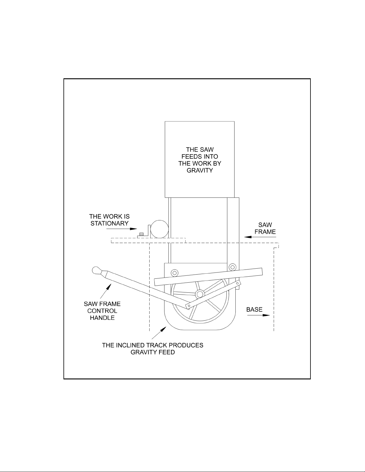
How The VSF-14 Band Saw Operates
Figure 1: How the VSF-14 Band Saw Operates
7

Introduction
This manual is provided by JET Equipment covering the safe operations and maintenance
procedures for Models VSF-14-1 and VSF-14-3. This manual contains instructions on installation,
safety precautions, general operating procedures, maintenance instructions and parts breakdown.
This machine has been designed and constructed to provide years of trouble free operation if used in
accordance to instructions set forth in this manual. If there are any questions or comments, please
contact either your local supplier or WMH Tool Group. WMH Tool Group can also be reached at our
web site: www.wmhtoolgroup.com.
Specifications
Model VSF-14-1 VSF-14-3
Blade Speeds (SFPM) 70, 140, 280, 580 70, 140, 280, 580
Height Capacity (max./in.) 14-1/2 14-1/2
Throat Capacity (max./in.) 8-1/2 8-1/2
Table Size (in.) 18-1/2 x 30-1/2 18-1/2 x 30-1/2
Table Height (in.) 30 30
Blade Wheel Diameter (in.) 14 14
Blade Length (approx./in.) 120 120
Blade Width (in.) 1/8 min. – 1 max. 1/8 min. – 1 max.
Floor Space Required (in.) 40L x 30-1/2W x 63H 40L x 30-1/2W x 63H
Motor
1HP, 1Ph,
115/230V, 60Hz
Net Weight (lbs.) 551 551
Figure 2: Specifications
Standard Features
• Welded frame and base of heavy gauge steel
• Swivel vise with scale for miter cuts
• Heavy duty precision ground cast iron table
• Four blade speeds (70, 140, 280, 580)
• Hydraulic feed control
• Counterweight for feed control
• Upper guide bar adjustment
• Guide rollers accept blade sizes: 1/8”, 1/4”, 3/8”, 1/2”, 5/8”, 3/4” and 1”
Standard Equipment
• Four foot pads
• Work light
• Chip tray
• Miter gauge
• Extension roller
• 5/8” Bi-metal blade
• Blade speed and pitch selector
• Conveniently located control panel
1HP, 3Ph,
230/460V, 60Hz
8
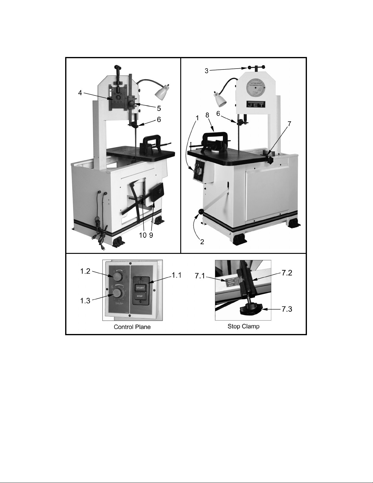
Description
Figure 3: Component Descriptions and Locations
1. CONTROL PANEL – The operating controls for the band saw are located on the base at the
front of the machine.
1.1. ON/OFF SWITCH – Turns the machine on or off.
1.2. SAW FRAME RELEASE KNOB – Turning this knob counterclockwise unlocks the
release lever (Item 2).
1.3. FEED RATE ADJUST KNOB – Used to adjust the hydraulic feed control rate.
2. SAW FRAME RELEASE LEVER – Pull up on this lever to release the saw frame after
unlocking it (Ref Item 1.2) and push down to return the saw frame to its rearmost position.
3. BLADE TENSION HANDLE – Used to set the correct blade tension. Also used to remove and
install the saw blade.
9

4. UPPER BLADE WHEEL BLADE TRACKING ADJUSTMENT (See Blade Tracking
Adjustments) – If your saw should get out of adjustment and the blade runs off the wheel or
runs back against the lip, loosen the two bottom bolts on the upper wheel slide. Turn the set
screw in or out to make the blade run approximately 1/32” away from the lip on the back of
the wheel. Tighten the two upper wheel slide bolts. IMPORTANT:
If the blade is allowed to
run against the lip on the wheel it will wear the lip off.
5. GUIDE BAR LOCK – Used to lock the roll guides in position.
6. BLADE GUIDE – Should be adjusted so it clears your work by approximately 1/2”. This will
insure maximum blade rigidity.
7. STOP CLAMP – Has two uses:
1) It can be set for the depth of cut;
2) If placed behind the frame, it will lock the frame in a
forward position for contour work.
7.1. Stop Clamp Scale – Shows the maximum depth of cut based on the size of blade you are
using.
7.2. Stop Clamp – Used with the Stop Clamp Scale (Figure 3 Item 7.1) to select the size of
the blade.
7.3. Lock Knob – To Lock the Stop Clamp.
8. C-CLAMP VISE – Used to hold stock in place during cutting. Graduations are provided to set
angle cuts.
9. COUNTERBALANCE WEIGHT – Used to maintain the blade pressure you desire.
10. HYDRAULIC CYLINDER – This should be adjusted to allow the frame to travel rapidly but not
free fall. This is a safety device and therefore should be kept properly adjusted.
Installation
General
• Do not install the machine in a damp, humid, dirty or badly illuminated environment.
Machine Setup
The band saw has been pre-adjusted at the factory and several test pieces have
been cut to verify cutting accuracy. Setup of the machine is limited to uncrating the
machine, securing it to the shop floor and connecting it to the electrical power source.
1. Remove the saw from the shipping skid; discard any hold-down devices.
2. Place the saw on the shop floor. This machine must be installed on a firm, level
surface. Make sure it is mounted securely to the floor using mounting anchors
secured through the holes in the base. In addition, adjust the level of the
worktable by adjusting the four feet pads.
3. If the saw will be used to cut long pieces of stock, allow plenty of room for the
length of the stock.
Electrical Connections
A qualified electrician should make the electrical connections
following all local and state codes.
The machine uses high voltage electrical power that poses a
significant risk of serious injury or death if proper precautions
are not observed. Make sure the machine is properly
grounded.
Connect the machine to the electrical power branch circuit. Observe the following
guidelines when connecting the saw to the power source.
1. Make sure the saw is disconnected from the electrical power branch circuit (trip
the required circuit breakers or remove the required fuses).
10

following table is recommended.
Cleaning
• All unpainted surfaces of the machine are treated with a rust preventative. Clean all
Operation
General
• Always wear approved safety glasses when using this machine. Before operating the
• Never use the machine if it is missing any guards or other safety devices.
• Maintain a balanced stance at all times so that you do not fall or lean against the saw
• Never leave the machine running. Always make sure it has come to a complete stop
Controls
• ON / OFF Switch (Figure 3 Item 1.1). Located on the right side of the control panel.
• Feed Control Knob (Figure 3 Item 1.3). Located on the left side of the control panel.
• Blade Speeds (Figure 5). The band saw has four blade speeds. The different speeds
2. Place a warning placard or tag on the service panel to prevent accidental
electrical shock.
3. When installing the motor power cord into a receptacle, make sure the plug is
compatible with the receptacle.
4. When using hard-wired connections, connect the wires as shown in the wiring
diagram.
5. Install the fuses or reset the breakers.
6. Check the operation of the saw.
For circuits that are a long distance from the electrical service box, the wire size
must be increased in order to deliver ample voltage to the motor. To minimize
power losses and to prevent motor overheating and burnout, the use of wire
sizes for branch circuits or electrical extension cords according to the
Conductor Length
AWG (American Wire Gauge) Number
120 Volt Lines 240 Volt Lines
0 – 50 Feet No. 14 No. 14
50 – 100 Feet No. 12 No. 14
Over 100 Feet No. 8 No. 12
Figure 4: Recommended Main Power Supply Wire Sizes
rust protected surfaces with a mild solvent. Do not use paint thinner, lacquer thinner,
gasoline or mineral spirits; these will damage painted surfaces.
machine, remove tie, rings, watches and other jewelry, and roll sleeves up past the
elbows. Remove all loose clothing and confine long hair. Non-slip footwear is
recommended. Do not wear gloves when operating the saw.
blade or other moving parts.
before leaving the machine.
Press this switch to start or stop the machine.
The knob is the hydraulic cylinder feed control valve. It is used to set the amount of
force that is applied to the saw blade. The feed rate is proportional to the opening of
the valve. Increasing the valve opening (counterclockwise) increases the feed rate;
decreasing the valve opening (clockwise) reduces the feed rate.
are obtained by changing the position of the motor drive V-belt on step pulleys.
Change blade speeds as follows. Caution: Change speeds only when the machine is
not running.
11

Changing blade speeds:
1. Disconnect the electrical power from the band saw branch circuit to prevent
accidental motor start-up.
2. Place the saw frame in the rearmost position by pushing down on the saw
frame release lever (Figure 3 Item 2) and lock it by turning the saw frame
release knob (Figure 3 Item 1.2) clockwise.
3. Remove the panel on the base to expose the V-belt and pulleys.
4. Lift the motor to loosen the belt.
5. Select the speed using the placard on the saw head. Put the V-belt in the
pulley grooves of the pulley for the desired speed (Refer to Figure 5 for belt
locations and the speeds available).
6. Lower the motor to tighten the V-belt.
Figure 5: Belt Speed/Position Relationship
Blade Selection
The band saw is delivered with a saw blade that is adequate for a variety of jobs on a
variety of common materials. Refer to Figure 5 for the speeds recommended for various
materials. These speeds, while appropriate for many common cutting needs, do not
encompass the wide variety of special blade configurations (tooth pitch and set) and
Blade Removal and Installation
special alloys for cutting unusual or exotic materials.
A coarse blade could be used for a solid steel bar, but a finer tooth blade would be used
on a thin-wall steel tube. In general, the blade choice is determined by the thickness of
the material; the thinner the materials; the finer the tooth pitch.
A minimum of three teeth should be on the work piece at all times for proper cutting. The
blade and work piece can be damaged if the teeth are so far apart that they straddle the
work piece.
For very high production cutting of special materials, or to hard-to-cut materials such as
stainless steel, tool steel or titanium, you can ask your industrial distributor for more
specific blade recommendations. The supplier that provides the work piece material
should be able to provide you with very specific instructions regarding the best blade (and
coolant or cutting fluid, if needed) for the material or shape supplied.
Use leather gloves when changing the saw blade to protect your hands from
cuts and scratches. Use protective eye wear that meets ANSI SPECIFICATION
Z87.1.
Disconnect the band saw from its electrical power source.
12

1. To remove the blade, place the saw frame in the rearmost position by pushing down
on the saw frame release lever (Figure 3 Item 2) and lock it by turning the saw frame
release knob (Figure 3 Item 1.2) clockwise.
2. Remove the panel on the base to expose the lower blade wheel.
3. Open the panel on the saw head to expose the upper blade wheel.
4. Remove the blade safety guard.
5. Turn the blade tension handle (Figure 3 Item 3) counterclockwise until the blade
hangs loose.
6. Use leather gloves to prevent cuts and scratches. Pull the blade off the drive wheels
and out of the blade guides. Store the removed blade carefully before proceeding.
7. To install the blade, slide the new blade into the blade guides.
8. Place the blade over the bottom wheel.
9. Place the blade over the top wheel. The teeth must point down toward the table.
10. Push the blade so it is seated against the shoulders of the wheels.
11. Turn the blade tension handle clockwise enough to hold the blade firmly in place.
12. Reconnect the saw to its electrical power source.
13. Turn the machine on to allow the blade to position itself. Check and adjust the
tracking of the blade. Refer to Blade Tracking Adjustments in this manual.
14. Turn the blade tension handle clockwise to finish tightening the blade. Do not overtighten the blade; tighten it just enough so it does not slip while cutting.
15. Install the wheel guards and blade covers.
The most common causes of your band saw not cutting straight are:
1. Blade tension is set to low.
2. The blade is either dull or worn on one side.
3. The blade is upside down. The teeth must point down toward the
Blade Break-In Procedures
New blades are very sharp and, therefore, have a tooth geometry that is easily damaged
if a careful break-in procedure is not followed. Consult the blade manufacturer’s literature
for break-in of specific blades on specific materials. However, the following procedure will
be adequate for break-in of JET-supplied blades on lower alloy ferrous materials.
1. Clamp a section of round stock in the vise. The stock should be two inches or larger
in diameter.
2. Operate the saw at low speed. Start the cut with a very light feed rate.
3. When the saw has completed about 1/3 of the cut, increase the feed rate slightly and
allow the saw to complete the cut.
4. Keep the feed rate at the same setting and begin a second cut on the same or similar
work piece.
5. When the saw has completed about 1/3 of the cut, increase the feed rate while
watching the chip formation until cutting is at its most efficient rate (refer to Evaluating
Cutting Efficiency in this manual). Allow the saw to complete the cut.
6. The blade is now considered ready for use.
Controlling the Cut
Hydraulic Feed Control
The weight of the saw frame provides the force needed to cut through the work piece.
The saw has a hydraulic cylinder that controls the feed rate.
The hydraulic feed control circuit consists of a single-acting hydraulic cylinder and a flowcontrol valve. The feed control cylinder resists motion in the forward direction to control
table.
13

the feed rate. The control cylinder offers no resistance when the saw frame is moved
backward. A knob on the control panel controls the rate at which the saw frame moves
forward. The control knob (needle valve) controls the rate at which the hydraulic fluid is
released from the hydraulic cylinder. When the needle valve is closed, the cylinder is
locked. With the needle valve slightly open, the cylinder permits slow, or light, force.
Opening the needle valve further increases the feed rate and applies more force to the
saw blade and the work piece.
The needle valve is adjusted until the saw is operating efficiently. The efficiency of
operation is usually evaluated by observing chip formation. (Refer to Evaluating Cutting
Efficiency for more information on cutting efficiency.
Evaluating Cutting Efficiency
Is the blade cutting efficiently? The best way to determine this is to observe the chips
formed by the cutting blade.
• If the chip formation is powdery, then the feed is much to light, or the blade is dull.
• If the chips formed are curled, but colored – blue or straw colored from heat generated
during the cut – then the feed rate is to high.
• If the chips are slightly curled and are not colored by heat – the blade is sufficiently sharp
and is cutting at its most efficient rate.
Setting the Vise for Angle Cuts
The vise can be adjusted through a 45
o
arc. Adjust as follows:
1. Loosen the hex head bolt and remove the taper pin on the vise.
2. Rotate the vise to the desired angle. For accurate cuts, use a variable protractor
to set the position of the jaw; align one side of the protractor with one side of the
blade.
3. Re-install the taper pin and tighten the hex head bolt on the vise.
Setting the Vise for Square Cuts
The procedure for setting the vise for square cuts is identical to setting for angle cuts (see
Setting the Vise for Angle Cuts) except that a machinist’s square is used to position the
vise.
Work Setup
1. Move the saw frame to its rearmost position by pushing down on the saw frame
release lever (Figure 3 Item 2) and lock it in place by turning the saw frame release
knob (Figure 3 Item 1.2) clockwise.
2. Turn the c-clamp handle counterclockwise enough to fit the stock.
3. Place the work piece on the worktable. For long work pieces, provide support at the
other end. If necessary, provide additional downward clamping to hold the work piece
securely on the worktable.
Setting the Blade Guide Bracket
4. Clamp the work piece in the vise by rotating the c-clamp handle clockwise.
Do not allow the blade to rest against the work piece when the saw is not
cutting.
The band saw has an adjustable blade guide bracket. The blade guide bracket allows
you to set the blade guide for varying heights of work pieces.
To make accurate cuts and prolong blade life, the blade guide bracket should be set one
inch above the piece to be cut. Adjust the bar position as follows:
14

1. Place the work piece in the vise and clamp tightly.
2. Loosen the locking knob on the back of the guide bracket (Figure 3 Item 5).
3. Slide the guide bracket to the desired position.
4. Tighten the locking knob to secure the guide bracket.
Starting the Saw
1. Make sure that the saw frame is in the rearmost position and turn the saw frame
release knob (Figure 3 Item 1.2) to the OFF (clockwise) position.
2. Clamp the work piece in the vise. (Refer to Figure 6 for examples of how different
shaped work pieces are clamped in the vise).
3. Be sure that the blade is not in contact with the work piece when the motor is started.
4. Start the motor and allow the saw to come up to speed.
5. Turn the feed rate knob clockwise all the way. This closes the hydraulic valve and
stops the feed rate.
6. Turn the saw frame release knob counterclockwise to the ON position.
7. Pull up on the saw frame release lever (Figure 3 Item 2) to release the saw frame.
8. Slowly let the saw feed into the work piece by turning the feed rate control knob
(Figure 3 Item 1.3) counterclockwise until the proper feed rate is reached (See
Evaluating Cutting Efficiency).
9. Do not force the cut. Let the weight of the saw provide the cutting force.
10. At the end of the cut, push down on the saw frame release lever to move the saw
frame back to the rearmost position and turn the saw frame release knob clockwise
to lock it.
Never operate the saw without the blade covers in place.
Make sure the blade is not in contact with the work piece when the motor is
started. Do not force the saw through the work piece.
15

Service and Maintenance
Adjustments
The efficient operation of the band saw is dependent upon the condition of the saw blade.
If the performance of the saw begins to deteriorate, the first item that you should check is
the blade.
If a new blade does not restore the machine’s cutting accuracy and quality, refer to the
troubleshooting guide (or the blade manufacturer’s guide) for conditions to consider and
adjustments that can be made to increase the life of the blade.
To change the blade, refer to the blade changing procedures in the Blade Selection
section of this manual.
Blade Tracking Adjustments
Blade tracking has been tested at the
factory. Adjustment is rarely required
when the blade is used properly and if
the blade is correctly welded. (Refer to
Figure 7 for location of blade tracking
adjustment setscrew).
1. Place the saw frame in its
rearmost position by pushing
down on the saw frame release
lever (Figure 3 Item 2) and lock
it in place by turning the saw
frame release knob (Figure 3
Item 1.2) clockwise.
2. Make sure the blade is properly
tensioned.
NOTE: Keep proper tension on
the blade at all times using the
blade tension adjustment.
3. Loosen the two bottom bolts
(Figure 6, Item B) on the wheel
slide.
While performing the following
steps, keep the blade from
rubbing excessively on the
shoulder of the wheel.
Excessive rubbing will
damage the wheel and/or the
blade.
4. Start the saw. Turn the setscrew
to tilt the idler wheel until the
blade is touching the shoulder
of the idler wheel.
5. Turn the setscrew (Figure 6,
Item A) so the blade starts to
move away from the shoulder of
the wheel; then immediately
turn the setscrew in the other
direction so the blade stops;
then moves slowly towards the
shoulder.
Figure 6: Blade Tracking Adjustment
16

Keep your fingers clear of the blade and wheel to avoid injury.
6. Turn the setscrew to stop the motion of the blade on the wheel as it gets closer to
the wheel shoulder. Put a six-inch length of paper between the blade and the
wheel. The paper should not be cut as it passes between the wheel shoulder and
the blade.
7. Turn the setscrew a small amount. Repeat the insertion of the paper between the
wheel shoulder and the blade until the paper is cut in two pieces.
NOTE: You may have to repeat the check with the paper several times before the
blade and the shoulder cut the paper into two pieces. Do not hurry the
adjustment. Patience and accuracy here will pay off with better, more accurate,
quieter cutting and much longer machine and blade life.
8. When the paper is cut, turn the setscrew slightly in the counterclockwise direction.
This assures that the blade is not touching the shoulder of the wheel.
9. Shut off the saw.
10. Tighten the two bottom bolts on the upper wheel slide (Figure 6, Item B).
Blade Guide Bearing Adjustment
Proper adjustment of the blade guide bearings is critical to efficient operation of the band
saw. The blade guide bearings are adjusted at the factory. They should rarely require
adjustment. When adjustment is required, readjust immediately. Failure to maintain
proper blade adjustment may cause serious blade damage or inaccurate cuts.
It is always better to try a new blade when cutting performance is poor. If performance
remains poor after changing the blade, make the necessary adjustments.
If a new blade does not correct the problem, check the blade guides for proper spacing.
For most efficient operation and maximum accuracy, provide 0.001” clearance between
the blade and the guide bearings. The bearings will still turn freely with this clearance. If
the clearance is incorrect, the blade may track off the drive wheel.
Disconnect the band saw from its electrical power source.
Check the blade to make sure the welded section is the same thickness as the
rest of the blade. If the blade is thicker at the weld, the guide bearings may be
damaged.
If required, adjust the guide bearings as follows:
1. The upper and lower blade guides are adjusted the same way.
2. Loosen the blade guide setscrews with an Allen wrench.
3. Position the bearing by turning
the eccentric shafts. Set the
clearance to approximately
0.001”. (See Figure 7).
4. Tighten the blade guide
setscrews with the Allen
wrench.
5. Use the same procedure to
adjust the other blade guide
bearing.
6. When the adjustment is correct,
the guide bearings should
rotate freely with slight pressure
of the finger (blade stopped).
Figure 7: Guide Bearing Adjustment
17

Cleaning
1. Clean off any oil and grease on the machine surfaces.
2. After cleaning, coat the machined surfaces of the band saw with medium
consistency machine oil. Reapply the oil coating at least every six months.
3. Clean up accumulated saw cuttings after use. Make sure the lead screw and the
rapid nut are kept free from saw cuttings and other material that would cause
damage.
Lubrication
Lubricate the following components at the recommended intervals using the lubricants
specified:
1. Ball bearings: the bearings are lubricated and sealed – periodic lubrication is not
required.
2. Blade guide bearing: the bearings are lubricated and sealed – periodic lubrication
is not required.
3. Upper wheel bushing: six to eight drops of oil each week.
4. Pivot points, shafts and bearing areas: six to eight drops of oil each week.
Changing the Drive Motor V-Belt
Disconnect the band saw from its electrical power source.
1. Move the saw frame to its rearmost position and by pushing down on the saw
frame release lever (Figure 3 Item 2) and lock it in place by turning the saw frame
release knob (Figure 3 Item 1.2) clockwise.
2. Remove the panel on the base to expose the belt and pulleys.
3. Pivot the motor upwards to loosen the belt.
4. Remove the worn belt.
5. Put the replacement belt in the pulley position for the speed you require. (Refer to
Figure 5 for belt locations and the speeds available).
6. Tighten the belt by pivoting the motor downward.
7. Replace the panel and unlock the saw frame.
Chip Brush and Chip Scraper Replacement
The purpose of
the chip brush and
chip scraper is to
remove chips from
the saw teeth, the
saw blade and the
lower blade wheel
so an excessive
amount of chips
doesn’t get into
the wheel guard
section of the saw.
Figure 8: Chip Brush and Chip Scraper Locations
With extended
use, this brush
and/or scraper will
become worn and
will require replacement.
18

Disconnect the band saw from its electrical power source.
1. Remove the two screws and washers holding the brush or scraper on.
2. Remove the worn brush or scraper.
3. Install the replacement brush or scraper.
4. Install the two screws and washers.
5. Adjust the brackets, if necessary, so that the brush makes slight contact with the
lower blade wheel and the scraper is as close as possible to the saw blade
without touching it.
Blade Guide Bearing Replacement
Disconnect the band saw from its electrical power source.
1. Remove the saw blade. (Refer to Blade Removal and Installation).
2. Remove the bearing locking screw
3. Remove the damaged bearing and bushing.
4. Separate the damaged bearing from the bushing.
5. Install the replacement bearing on the bushing.
6. Install the bearing locking screw.
7. Install the saw blade. (Refer to Blade Removal and Installation).
8. Adjust the bearing clearance. (Refer to Blade Guide Bearing Adjustment).
Drive Motor Replacement
Disconnect the band saw from its electrical power source.
1. Remove the drive motor V-belt. (Refer to Changing the Drive Motor V-Belt).
2. Loosen the setscrew that holds the motor pulley to the shaft and remove the
pulley.
3. Open the motor junction box and disconnect the power cord wires from their
terminals.
4. Remove the nuts, washers and bolts that secure the motor to the mounting plate.
5. Installation of the motor is the reverse of the above steps. (Refer to Changing the
Drive Motor V-Belt and the electrical schematics at the end of this manual).
Adjusting or Replacing the Counterbalance
The counterbalance is located on the base of the saw. It is used to adjust the amount of
force the saw puts on the work piece when the hydraulic control cylinder is open.
Disconnect the band saw from its electrical power source.
1. Lock the saw frame in its rearmost position by pushing down on the saw frame
release lever (Figure 3 Item 2) and lock it in place by turning the saw frame
release knob (Figure 3 Item 1.2) clockwise.
2. Turn the handle on the counterweight counterclockwise to loosen it (Figure 3
Item 9).
3. Slide the counterweight along the bar to the proper location.
4. Turn the handle on the counterweight clockwise to tighten it (Figure 3 Item 9).
19

Replacing the Drive Wheel (Lower Wheel)
Disconnect the band saw from its electrical power source.
1. Remove the saw blade. (Refer to Blade Removal and Installation).
2. Loosen the setscrew in the wheel hub.
3. Pull the wheel from the speed reducer shaft.
4. Examine the drive edge and shoulder of the wheel for damage. Replace the
wheel if it’s damaged.
5. Install the wheel.
6. Tighten the setscrew in the wheel hub.
7. Install the saw blade. (Refer to Blade Removal and Installation).
Replacing the Idler Wheel or Bearings (Upper Wheel)
Disconnect the band saw from its electrical power source.
1. Remove the saw blade. (Refer to Blade Removal and Installation).
2. Remove the retaining ring and shim from the shaft.
3. Remove the wheel and the bronze bearing.
4. Examine the drive edge and shoulder of the wheel for damage. Replace the
wheel if it’s damaged.
5. Install the bearing and the wheel.
6. Install the retaining ring and shim on the shaft.
7. Install the saw blade. (Refer to Blade Removal and Installation).
20

Troubleshooting
Problem Probable Cause Suggested Remedy
Excessive Blade
Breakage
1. Material is loose in the
vise.
2. Incorrect speed or feed.
3. Blade pitch is too coarse
for the material.
4. Incorrect blade tension.
5. Saw blade is in contact
with the work piece before
the saw is started.
6. Blade rubs on the wheel
flange.
7. Misaligned blade guides.
8. Cracking at the weld.
Premature Blade
Dulling
1. Blade pitch is too coarse.
2. Blade speed is too high.
3. Inadequate feed pressure.
4. Hard spots in the work
piece.
5. Scale on/in the work piece.
6. Work hardening of material
(especially stainless steel).
7. Insufficient blade tension.
8. Operating the saw without
pressure on the work
piece.
Blade Is Twisting 1. Blade is binding in the cut.
2. Blade tension is too high.
1. Clamp work securely.
2. Check the Machinist’s
Handbook for the
speed/feed appropriate for
the material being cut.
3. Check the Machinist’s
Handbook for the
recommended blade type.
4. Adjust the blade tension
just to the point where the
blade does not slip on the
wheel. (Refer to Figure 3
Item 3).
5. Start the motor before
placing the saw blade
against the work piece.
6. Adjust the blade tracking.
(See Blade Tracking
Adjustment).
7. Adjust the blade guides.
(See Blade Guide Bearing
Adjustment).
8. Use a longer annealing
cycle.
1. Use a finer tooth blade.
2. Use a lower blade speed.
(See Figure 5).
3. Decrease the feed
pressure. (See Figure 3
Item 1.3).
4. Increase the feed pressure
(hard spots). (See Figure 3
Item 1.3).
5. Reduce the blade speed
and increase the feed
pressure (scale). (See
Figure 3 Item 1.3 and
Figure 5).
6. Increase the feed pressure.
(See Figure 3 Item 1.3).
7. Increase the tension to the
proper level. (See Figure 3
Item 3).
8. Do not run the blade in/on
the material at idle.
1. Decrease the feed
pressure. (See Figure 3
Item 1.3).
2. Decrease the tension on
the blade. (See Figure 3
Item 3).
21

Troubleshooting
Problem Probable Cause Suggested Remedy
Unusual Wear On
Side/Back Of Blade
Bad Cuts (Crooked) 1. Work piece is not square
Bad Cuts (Rough) 1. Blade speed is too high for
1. Blade guides are worn.
2. Blade guide bearings are
not adjusted.
3. Blade guide bearing
bracket is loose.
with the blade.
2. Feed pressure is too high.
3. Guide bearings are not
adjusted properly.
4. Inadequate blade tension.
5. Span between the two
blade guides is too wide.
6. Dull blade.
7. Incorrect blade speed.
8. Blade guide assembly is
loose.
9. Blade guide bearing
assembly is loose.
10. Blade track is too far away
from the wheel flanges.
11. Guide bearing is worn.
the feed pressure.
2. Blade teeth are too coarse.
1. Replace the blade guides.
(See Setting the Blade
Guide Bracket).
2. Adjust the blade guide
bearings. (See Blade
Guide Bearing
Adjustment).
3. Tighten the blade guidebearing bracket. (See
Blade Guide Bearing
Adjustment).
1. Adjust the vise so that it is
square with the blade.
(Always clamp the work
piece tightly in the vise).
2. Lower the feed pressure.
(See Figure 3 Item 1.3).
3. Adjust the guide bearing
clearance to 0.001” (0.002”
maximum). (See Blade
Guide Bearing
Adjustment).
4. Gradually increase the
blade tension. (See Figure
3 Item 3).
5. Move the blade guide
bracket closer to the work
piece. (See Setting the
Blade Guide Bracket).
6. Replace the blade. (See
Blade Removal and
Installation).
7. Check the blade speed.
(See Figure 5).
8. Tighten the blade guide
assembly. (See Setting the
Blade Guide Bracket).
9. Tighten the blade guide
bearing assembly. (See
Blade Guide Bearing
Adjustment).
10. Adjust the blade tracking.
(See Blade Tracking
Adjustment).
11. Replace the worn bearing.
(See Blade Guide Bearing
Replacement).
1. Reduce the blade speed
(See Figure 5).
2. Replace the blade with a
finer tooth blade.
22

Replacement Parts
This section provides exploded view illustrations that show the replacement parts for the
Models VSF-14-1 and VSF-14-3 Self-Feed Vertical Band Saw. Also provided are parts
listings that provide part numbers and descriptions. The item numbers shown in the
exploded views match the item numbers in the parts listing.
Order replacement parts from:
Identify the replacement part by the part number shown in the parts listing. Be sure to
include the model number and serial number of your machine when ordering replacement
parts to assure that you will receive the correct part.
WMH TOOL GROUP
2420 Vantage Drive
Elgin, Illinois 60123
Ph.: 888-594-5866
Fax: 800-626-9676
www.wmhtoolgroup.com
23

24
Figure 9: Exploded View of the VSF-14 Saw Frame

Parts List for VSF-14 Saw Frame
Item Part No. Description Size Qty.
1 5519711 Blade Tension Knob 2
2 5519712 Blade Tension Handle 1
3 5519718 Flat Washer 5/8” x 40 x T3 2
4 5519713 Spring 1
5 5519714 Screw Rod 1
6 5519715 Bracket 1
7 TS-0680042 Flat Washer 3/8” x 23 x T2 2
8 TS-0209051 Socket Head Cap Screw 3/8-16 x 1-1/2” 2
9 5519716 Blade Wheel Slide Race 2
10 TS-0720091 Lock Washer 3/8” 6
11 TS-0209031 Socket Head Cap Screw 3/8-16 x 3/4” 6
12 5519717 Drive Shaft Holder 1
13 5519718 Flat Washer 5/8” x 40 x T3 1
14 TS-0561072 Hex Nut, Full 5/8-18 1
15 TS-0561072 Hex Nut, Full 5/8-18 1
16 5519719 Blade Wheel Slide 1
17 TS-0680042 Flat Washer 3/8” 4
18 TS-0209091 Socket Head Cap Screw 3/8-16 x 2” 4
19 TS-0060051 Hex Cap Screw 3/8-16 x 1” 1
20 TS-0813021 Flat Slotted Machine Screw 1/4-20 x 3/8” 1
21 TS-0680021 Flat Washer 1/4” 1
22 5519720 Tension Indicator 1
23 5519721 Rivet 2 x 8 2
24 5519722 Tension Label 1
25 5519723 Upper Blade Guide Handle 3/8” x 1” 1
26 5519724 Spring Pin 6 x 50 2
27 5519725 Upper Blade Guide Bracket 1
28 TS-0209091 Socket Head Cap Screw 3/8-16 x 2” 2
29 TS-0680042 Flat Washer 3/8” 2
30 TS-0207011 Socket Head Cap Screw 1/4-20 x 3/8” 1
31 5519726 Upper Blade Guide Slide 1
32 TS-0050021 Hex Cap Screw 1/4-20 x 5/8” 1
33 5519727 Spring Pin 6 x 25 1
34 5519728 Blade Guide Shaft 1
35 TS-0208011 Socket Head Cap Screw 5/16-18 x 3/8” 1
36 5519729 Upper Shaft 1
37 TS-0208021 Socket Head Cap Screw 5/16-18 x 1/2” 2
38 5519730 Blade Guide Mtg. Bracket 2
39* 5519731 Bearing Shaft Assembly 4
40 5519733 Blade Guide Knob 1/4” x 5/8” 1
41 5519734 Saw Blade Safety Cover 1
42 5519735 Special Washer 3
43 5519736 Eccentric Shaft 1
44* 5519737 Smooth Wheel Assembly 1
45 TS-0680061 Flat Washer 1/2” 1
46 TS-0070031 Hex Cap Screw 1/2-13 x 1-1/2” 1
47 TS-0090061 Hex Cap Screw 3/8-16 x 1-1/4” 2
48 TS-0570032 Hex Nut, Full 3/8-24 2
49 5519740 Saw Frame 1
50 5519741 Gearbox Pulley 1
51 5519742 Key 5 x 5 x 40 1
52* 5519743 Gear Box Assembly 1
53
5519766 V-Belt
3V-320 1
25

Parts List for VSF-14 Saw Frame
Item Part No. Description Size Qty.
54
55
56
57
58
59
60
61
62
63
64
65
66
67
68
69*
70
71
72
73
74
75
76
77
78
79
80
81
82
83
84
85
86
87
88
89
90
91
92
93
94
95
96
97
98
99
100
101
102
103
104
105
106
5519767 Drive Motor Pulley
TS-148201 Hex Cap Screw
5519768 Motor
5521706 Motor
5519769 Key
TS-0570032 Hex Nut, Full
TS-0720091 Lock Washer
5519770 Motor Mounting Bracket
TS-0060051 Hex Cap Screw
TS-0570032 Hex Nut, Full
TS-0680042 Flat Washer
5519771 Motor Mounting Bracket
TS-0209051 Socket Head Cap Screw
TS-0720091 Lock Washer
TS-0060051 Hex Cap Screw
5519772 Eccentric Bolt
5519773 Smooth Wheel Assembly
5519775 Flat Washer
5519776 Counter Balance Bracket
TS-0680021 Flat Washer
TS-0207021 Socket Head Cap Screw
TS-0680041 Flat Washer
TS-0060071 Hex Cap Screw
TS-0070041 Hex Cap Screw
TS-0720111 Lock Washer
5519777 Eccentric Bracket
5519778 Eccentric Bolt
TS-0561051 Hex Nut, Full
TS-0680061 Flat Washer
5519779 Brush Mounting Bracket
5519780 Brush
TS-0813032 Slotted Round Head Screw
TS-0680021 Flat Washer
TS-0813032 Slotted Round Head Screw
5519781 Shaft Bolt
TS-0680042 Flat Washer
5519782 Handle Lever
TS-0209061 Socket Head Cap Screw
TS-0680042 Flat Washer
5519783 Spring Pin
TS-0720091 Lock Washer
TS-0209081 Socket Head Cap Screw
TS-0051021 Hex Cap Screw
5519784 Lower Blade Guide Bracket
5519785 Lower Blade Guide Shaft
5519786 Chip Scraper
TS-0680021 Flat Washer
TS-0813032 Slotted Round Head Screw
5519787 Drive Wheel
5519788 Plastic Pad
5519789 Flat Washer
TS-0060051 Hex Cap Screw
5519790 Saw Blade
5519791 Bolt
1
M6 x 10 2
1HP, 1 Phase 1
1HP, 3 Phase 1
5 x 5 x 40L 1
3/8-24 2
3/8” 2
1
3/8-16 x 1” 2
3/8-24 2
3/8” 4
1
3/8-16 x 1” 2
3/8” 2
3/8-16 x 1” 2
1
2
1/4” 1
1
1/4” 1
1/4-20 x 1/2” 1
3/8” 2
3/8-16 x 1-1/2” 1
1/2-13 x 1-3/4” 1
1/2” 1
1
1
1/2-13 2
1/2” 2
1
1
1/4-20 x 1/2” 2
1/4” 2
1/4-20 x 1/2” 2
1
3/8” 1
1
3/8-16 x 1-1/4” 1
3/8” 2
6 x 20 2
3/8” 2
3/8-16 x 1-3/4” 2
5/16-18 x 5/8” 1
1
1
1
1/4” 2
1/4-20 x 1/2” 2
1
2
10.5 x 40 x 5 1
3/8-16 x 1” 1
5/8”T x 19 x 0.9 x 3048L 1
1
26

Parts List for VSF-14 Saw Frame
Item Part No. Description Size Qty.
107*
108
109
110
111
112
113
114
115
116
117
118
119
120
121
122
123
124
125
126
206
207
5519792 Idler Wheel Assembly
5519795 Idler Wheel Shaft
5519796 Work Light
5519797 Door Handle
TS-0680021 Flat Washer
TS-0570032 Hex Nut, Full
TS-0680042 Flat Washer
TS-0207011 Socket Head Cap Screw
TS-0680021 Flat Washer
5519798 Speed Indicator Dial
5519799 Flat Washer
5519800 Pad
5519801 Dial Knob
5519802 Dial Scale
5519803 Dial Base
TS-0813021 Slotted Flat Head Screw
TS-0680021 Flat Washer
5519804 Idler Wheel Cover
TS-0680021 Flat Washer
TS-0561011 Hex Nut, Full
5521710 Hex Cap Screw
5521711 Overload
1
1
1
1/4” 2
1/4” 2
3/8-24 2
3/8” 2
1/4-20 x 3/8” 1
1/4” 1
1
1
1
1
1
1
1/4-20 x 3/8” 5
1/4” 5
1
1/4” 1
1/4-20 1
1/8” x 3/8” 4
16A (1PH Only) 1
* = See Separate Parts List
27

28
Figure 10: Exploded View of the VSF-14 Base

Parts List for the VSF-14 Base
Item Part No. Description Size Qty.
127
128
129
130
131
132
133
134
135
136
137
138
139
140
141
142
143
144
145
146
147
148
149
150
151
152
153
154
155
156
157
158
159
160
161
162
163
164
165
166
167
168
169
170
171
172
173
174
175
176
177
178
179
180
5519805 C-clamp Vise
5519806 C-clamp Knob
5519807 C-clamp Handle
5519808 Lead screw
5519809 Spring
5519810 Ball
5519811 Shaft
5519812 Pivot Pin
5519813 Vise Base
5519814 Vise Bracket
TS-0208061 Socket Head Cap Screw
5519815 Degree Gauge
5519816 Rivet
TS-0209071 Hex Cap Screw
TS-0720091 Lock Washer
TS-0680041 Flat Washer
5519819 Saw Table
5519820 Stock Roller Mtg. Bracket
TS-0720081 Lock Washer
TS-0051051 Hex Cap Screw
5519821 Stock Roller
5519822 Stock Roller Mtg. Bracket
TS-0680061 Flat Washer
5519823 Return Lever
5519824 Plastic Handle
TS-0680042 Flat Washer
TS-0570032 Hex Nut, Full
5519825 Control Box
5519826 Control Panel Cover
5519827 Control Panel Label
JMD18-056A Power ON/OFF Switch
5519829 Hydraulic ON/OFF Knob
5519830 Feed Rate Adjust Knob
5519831 Slotted Round Head Screw
TS-0813051 Slotted Flat Head Screw
5519833 Chip Collector Drawer
TS-0209031 Socket Head Cap Screw
TS-0680042 Flat Washer
TS-0070071 Hex Cap Screw
TS-0680061 Washer
TS-0561051 Hex Nut, Full
5519836 Stop Pad
5519837 Stop Bracket
5519838 Stop Bracket Knob
TS-0680021 Flat Washer
TS-0813051 Slotted Flat Head Screw
5519841 Right Side Panel
5519842 Position Label
5519843 Spring Pin
TS-0680042 Flat Washer
TS-0720091 Lock Washer
TS-0060051 Hex Cap Screw
TS-0570032 Hex Nut, Full
TS-0680042 Flat Washer
1
2
1
1
1
OD = 5mm 1
1
1
1
1
5/16-18 x 1 2
1
2 x 8 3
3/8-16 x 1-1/2” 1
3/8” 1
3/8” 1
1
1
5/16” 4
5/16-18 x 1” 4
1
1
1/2” 2
1
1
3/8” 2
3/8-24 1
1
1
1
120/220/440V 3 Phase 1
1
1
3/16” x 1/2” 4
1/4-20 x 5/8” 4
1
3/8-16 x 3/4” 2
3/8” 2
1/2-13 x 2-1/2” 1
1/2” 2
1/2-13 1
1
1
3/8” x 2” 1
1/4” 4
1/4-20- x 5/8” 4
1
1
6 x 45 2
3/8” 8
3/8” 1
3/8-16 x 1” 4
3/8-24 1
3/8” 4
29

Parts List for the VSF-14 Base
Item Part No. Description Size Qty.
181
182
183
184
185
186
187
188
189
190
191
192
193
194
195
196
196-1
197
198
199
200
201
202
203
204
205
208
TS-0070071 Hex Cap Screw
TS-0561051 Hex Nut, Full
TS-0680042 Flat Washer
TS-0570032 Hex Nut, Full
5519845 Weight Mounting Bracket
TS-0208041 Socket Head Cap Screw
5519846 Pivot Shaft
TS-0209091 Socket Head Cap Screw
5519847 Coupler
5519848 Weight Knob
5519849 Counterbalance Weight
5519850 Saw Base
5519851 Connector
5519852 Connector Mounting Nut
5519853 Control Box
5521707 Worklight Power Cable
5519854 Power Cable with Plug
5519855 Left Side Panel
TS-0680021 Flat Washer
TS-081F032 Phillips Pan Head Screw
5519857 Hydraulic Cylinder Assy.
TS-0561031 Hex Nut, Full
5519858 Cylinder Lower Support
TS-0060091 Hex Cap Screw
5521798 Leg
5521709 Socket Head Cap Screw
5521716 Taper Pin
1/2-13 x 2-1/2” 4
1/2-13 4
3/8” 1
3/8-24 1
1
5/16-18 x 3/4” 1
1
3/8-16 x 2” 1
1
3/8-16 x 2” 1
1
1
PG13.5 2
5
1
115V Only 1
115V Only 1
1
1/4” 4
1/4-20 x 1/2” 4
1
3/8-16 1
1
3/8-16 x 2-1/2” 1
4
3/8-16 x 1” 8
1
* = See Separate Parts List
30

Figure 11: Exploded View of the VSF-14 Gear Box Assembly
Parts List for the VSF-14 Gear Box Assembly
Item Part Number Description Size Qty.
52-1 5519744 Gear Box 1
52-2 BB6204Z Bearing 6204Z 2
52-3 5519745 Oil Seal TC20 x 32 x 7B 1
52-4 5519746 O-Retainer Ring ID45.7 x 2.62W 2
52-5 5519747 Gearbox Drive Shaft Cover 1
52-6 TS-0720071 Lock Washer 1/4” 4
52-7 TS-0207041 Socket Head Cap Screw 1/4-20 x 3/4” 4
52-8 5519748 Oil Level Gauge OD = 26mm 1
52-9 5519749 Oil Plug PT1/4” 1
52-10 5519750 Worm Shaft 1
52-11 5519751 O-Retainer Ring ID113.97 x 2.62W 1
52-12 5519752 O-Retainer Ring ID61.6 x 2.62W 1
52-13 5519753 End Seal Cover 1
52-14 TS-0720071 Lock Washer 1/4” 4
52-15 TS-0207041 Socket Head Cap Screw 1/4-20 x 3/4” 4
52-16
52-17
52-18
52-19
52-20
52-21
52-22
5519754 Ventilation Bolt
5519755 Bearing
5519756 Transmission Gear
5519757 Key
5519758 Bushing
5519759 C-Retainer Ring
BB6206Z Bearing
5/8”-18UNF 1
6205Z 1
1
8 x 7 x 28 1
1
S30 1
6206Z 1
31

Parts List for the VSF-14 Gear Box Assembly
Item Part Number Description Size Qty.
52-23
52-24
52-25
52-26
52-27
52-28
52-29
52-30
52-31
52-32
5519760 Oil Seal
5519761 Main Oil Seal Cover
5519762 Key
5519763 Socket Head Cap Screw
TS-0207041 Socket Head Cap Screw
5519764 Main Shaft Cover
5519765 Main Shaft
TS-0090061 Hex Cap Screw
TS-0720091 Lock Washer
TS-0570032 Hex Nut, Full
TC38 x 52 x 7B 1
1
8 x 7 x 30 1
3/16” x 1/2” 3
1/4-20 x 3/4” 3
1
1
3/8-16 x 1-1/4” 3
3/8” 3
3/8 –24 3
32
Figure 12: Exploded View of the VSF-14 Bearing Shaft Assembly
Parts List for the VSF-14 Bearing Shaft Assembly
Item Part Number Description Size Qty.
39-1 5521712 Ball Bearing 627-2Z 8
39-2 5521713 Blade Wheel 4
39-3 5521714 E Retaining Ring E7 4
39-4 5519732 Bearing Shaft 4
39-5 5521715 C Retaining Ring 4

Figure 13: Exploded View of the VSF-14 Smooth Wheel Assembly
Parts List for the VSF-14 Smooth Wheel Assembly
Item Part Number Description Size Qty.
44-1 5519738 Smooth Wheel 1
44-2 5519739 Bearing 2
69-1
69-2
5519774 Smooth Wheel
BB6201Z Bearing
2
6201Z 4
Figure 14: Exploded View of the VSF-14 Idler Wheel
Parts List for the VSF-14 Idler Wheel Assembly
Item Part Number Description Size Qty.
107-1
107-2
107-3
5519793 Idler Wheel
BB6205ZZ Bearing
5519794 C-Retainer Ring
1
6205ZZ 2
2
33

(115 Volts, Single Phase)
115 Volts, Single Phase
(230 Volts, Single Phase)
230 Volts, Single Phase
Electrical Schematics
34
Figure 15: Electrical Schematics for Single Phase Motor

(230 Volts, Three Phase)
230 Volts, Three Phase
(460 Volts, Three Phase)
460 Volts, Three Phase
Figure16: Electrical Schematics for Three-Phase Motor

WMH TOOL GROUP
2420 Vantage Drive
Elgin, Illinois 60123
Ph.: 847-851-1000
Fax: 800-626-9676
www.wmhtoolgroup.com
Copyright WMH Tool Group
 Loading...