

Page 1
.JET
EQUIPMENT & TOOLS
OPERATOR'SMANUAL
VBS-1408/1610 Metalworking Bandsaw
(VBS-1610 shown)
P.O.BDX1349
AUBURN,WA98071-1349
.JETEQUIPMENT a TOOLS.INC.
A WMH -Walter Meier Holding Company
[20BJ351-8a:D
FAX(206) 939-8001
No. M-414485 2/97
Page 2
Important Information
1YEAR
LIMITED WARRANTY
JET offers a one year limited
warranty on this product
REPLACEMENT PARTS
Replacementpartsfor thistool are availabledirectlyform JET Equipment& Tools.
To place an order, call 1-800-274-6848. Pleasehavethe following informationready:
1. Visa, MasterCard,or DiscoverCard number
2. Expirationdate
3. Part number listed within this manual
4. Shippingaddress other than a PostOffice box.
REPLACEMENT PART WARRANTY
JET Equipment & Tools makes every effortto assurethat parts meet highquality and durability standards
and warrants to the original retail consumer/purchaserof our partsthat each such part(s) to be free from
defects in materials and workmanship for a period of thirty (30)days from the date of purchase.
PROOF OF PURCHASE
Please retain your dated sales receiptas proof of purchaseto validatethe warranty period.
LIMITED TOOL AND EQUIPMENT WARRANTY
JET makes every effort to assure that its products meet high quality and durability standards and warrants to the
original retail consumer/purchaser of our products that each product be free from defects in materials and
workmanship as follows: 1 YEAR LIMITED WARRANTY ON THIS JET PRODUCT. Warranty does not apply to
defects due directly or indirectly to misuse, abuse, negligence or accidents, repairs or alterations outside our
facilities or to a lack of maintenance. JET LIMITS ALL IMPLIED WARRANTIES TO THE PERIOD SPECIFIED
ABOVE FROM THE DATETHE PRODUCTWAS PURCHASEDAT RETAIL. EXCEPTAS STATED HEREIN, ANY
IMPLIED WARRANTIES OR MECHANTABILITY AND FITNESS ARE EXCLUDED. SOME STATES DO NOT
ALLOW LIMITATIONS ON HOW LONG THE IMPLIED WARRANTY LASTS, SO THE ABOVE LIMITATION MAY
NOT APPLY TO YOU. JET SHALL IN NO EVENT BE LIABLE FOR DEATH, INJURIES TO PERSONS OR
PROPERY OR FOR INCIDENTAL, CONTINGENT,SPECIAL OR CONSEQUENTIAL DAMAGES ARISING FROM
THE USE OF OUR PRODUCTS. SOME STATES DO NOT ALLOW THE EXCLUSION OR LIMITATION OF
INCIDENTALOR CONSEQUENTIALDAMAGES, SOTHE ABOVE LIMITATIONOR EXCLUSION MAY NOTAPPLY
TO YOU. To take advantage of this warranty, the product or part must be returned for examination, postage
prepaid, to an authorized service station designated by our Auburn office. Proof of purchase date and an
explanation of the complaint mustaccompany the merchandise. Ifour inspection discloses a defect, JET will either
repair or replace the product or refund the purchase price, if we cannot readily and quickly provide a repair or
replacement, if you are willing to accept such refund. JET will return repaired product or replacement at JET's
expense, but if it is determined there is no defect, or that the defect resulted from causes not within the scope of
JET's warranty, then the user must bear the cost of storing and returning the product. This warranty gives you
specific legal rights, and you have other rightswhich vary from stateto state.
JET Equipment &Tools. P.O.Box 1349,Auburn, WA98071-1349. (206)351-6000
Page 3
&, WARNING
.
Read and understand the entire
.
Replacewarning labels if they become
instruction manual before operating
obscuredor removed.
machine.
.
Make certain the motor switch is in the OFF
.
This manual is intendedto familiarize
positionbeforeconnecting the machineto
you with the technical aspects of this the powersupply.
bandsaw. It is not, norwas it intended
to be, a training manual.
.
Giveyourworkundividedaftention.
Lookingaround,carryingona
.
This machine is designed and intended
conversation,and"horse-play" are careless
for use by properly trained and
acts that can result inserious injury.
experienced personnelonly. If you are
not familiar with the proper safe use of a
.
Keepvisitors a safe distance from the work
bandsaw, do not use this machine until
area.
proper training and knowledge has been
obtained.
.
Use recommendedaccessories; improper
accessories may be hazardous.
.
Always wear approved safety glasses/face
shields while usingthis machine.
.
Makea habitof checking to see that keys
andadjustingwrenchesareremoved
.
Make certain the machine is properly
beforeturningon the machine.
grounded.
.
Never attemptany operation or adjustment
.
Before operating the machine,removetie, if the procedure is not understood.
rings,watches, otherjewelry, and roll up
sleeves above the elbows. Removeall
.
Keepfingers away from the bladewhile in
loose clothing and confinelong hair. Do operation.
not wear gloves.
.
Keepbelt guard in place and in working
.
Keepthe floor around the machineclean
order.
and free of scrap material, oil and grease.
.
Never force the cutting action.
.
Keep machine guards in place at all times
whenthemachineisinuse. If removedfor
.
Do notattempt to adjust or remove tools
maintenance purposes,use extreme during operation.
caution and replacethe guards
immediately.
.
Always keep the blade sharp.
.
Do not over reach. Maintaina balanced
.
Always use identicalreplacement parts
stance at all times so thatyou do not fall or
when servicing.
lean against bladesor other movingparts.
.
Readand understandall warnings posted
.
Make all machine adjustmentsor
on the machine.
maintenancewith the machine unplugged
from the power source.
.
Failureto comply with all of these warnings
may cause serious injury.
.
Use the righttool. Don'tforce a toolor
attachment to do a job which it was not
designed for.
Page 4
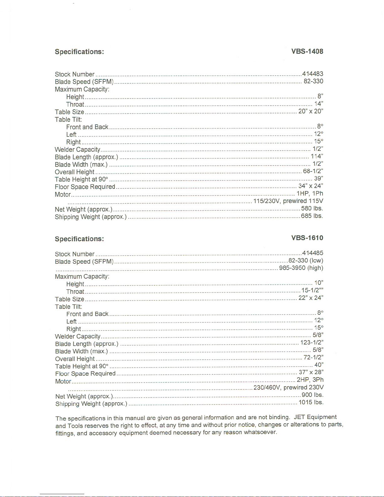
Specifications:
VBS-1408
Stock Number .414483
Blade Speed (SFPM) 82-330
Maximum Capacity:
Height 8"
Throat 14"
Table Size 20" x 20"
Table Tilt:
Front and Back ... ... ......... ....,.... ...8°
Left 12°
Right 15°
Welder Capacity 1/2"
Blade Length(approx.) 114"
BladeWidth (max.) ... ...... ...... ... .................. ... 1/2"
Overall Height .68-1/2"
Table Height at 90° 39"
Floor Space Required 34" x 24"
Motor 1HP, 1Ph
115/230V,prewired 115V
NetWeight (approx.) 580 Ibs.
ShippingWeight (approx.) 685 Ibs.
Specifications:
VBS-1610
Stock Number .414485
Blade Speed (SFPM). .82-330(low)
...... ... ...... ...... ...... ......... 985-3950 (high)
Maximum Capacity:
Height 10"
Throat ...15-1/2''''
Table Size 22" x 24"
Table Tilt:
Front and Back.. ... ... ...... ... ...... ...... 8°
Left ... ......... ... ...... ...... ...... ... , 12°
Right 15°
Welder Capacity 5/8"
Blade Length (approx.) ..." .." , 123-1/2"
BladeWidth (max.) ... ...... ...... ...... .................. ..,.. 5/8"
Overall Height .72-1/2"
Table Height at 90° 40"
Floor Space Required 37" x 28"
Motor 2HP, 3Ph
230/460V, prewired 230V
NetWeight (approx.) 900 Ibs.
ShippingWeight (approx.) 1015 Ibs.
The specifications in this manualare given as general informationand are not binding. JET Equipment
and Tools reservesthe right to effect,at anytime and without prior notice,changes or alterationsto parts,
fittings, and accessory equipmentdeemed necessaryfor any reasonwhatsoever.
Page 5

Uncrating and Clean-Up
1. Finishuncrating the bandsaw. Contactyour
distributor if any damage hasoccurred during
shipping.
2. Remove any preservativewith keroseneor
diesel oil. Donot use gasoline, paint thinner, or
any cellulose-based product. Thesewill damage
painted surfaces.
3. Removetwo hex cap screws from leftside ofthe
vertical column. Attach shear assembly (A, Fig.
1) to column by inserting hex cap screws.
Installation
1. Removethree nuts and washers holdingthe
bandsaw to the shippingcrate bottom.
2. Using the lifting ring, liftthe bandsaw into it's
permanent location. For best performance,the
bandsaw should be boltedto thefloor aftera
level position has beenfound.
3. Using a square, adjust the table 90 degreesto
the blade bothfront to backand side to side.
Loosen the hex cap screws below the tableto
move it and tighten to hold the table inplace. If
necessary, adju'stthe pointersto zero should
they read differentonce the table is
perpendicular to the blade in bothdirections.
4. To level the machine, place a machinist'slevel
on the table and observe in both directions.
5. Use metal shims under the appropriatehold
down screw. Tighten screw and recheck for
level.
6. Adjust with additional shims,as required,until
the table is level when all mountingscrews (or
nuts) aretight.
A
Figure 1
Page 6
Electrical Connections
The VBS-1408 bandsaw is ratedat 115/230Vand
comes from the factory prewired 115V.
The VBS-1610 bandsaw is ratedat 230/460Vand
comes from the factory prewired230V.
To switch to from 115Vto 230V (or230Vto 460V)
operation,follow the wiringdiagramfoundon the
inside cover of the motorjunction box.
The bandsaw must be grounded. A qualified
electrician can make the proper electrical
connections and confirm the power on site is
compatible with the saw.
Before hooking upto the power source, makesure
the switch is in the off position.
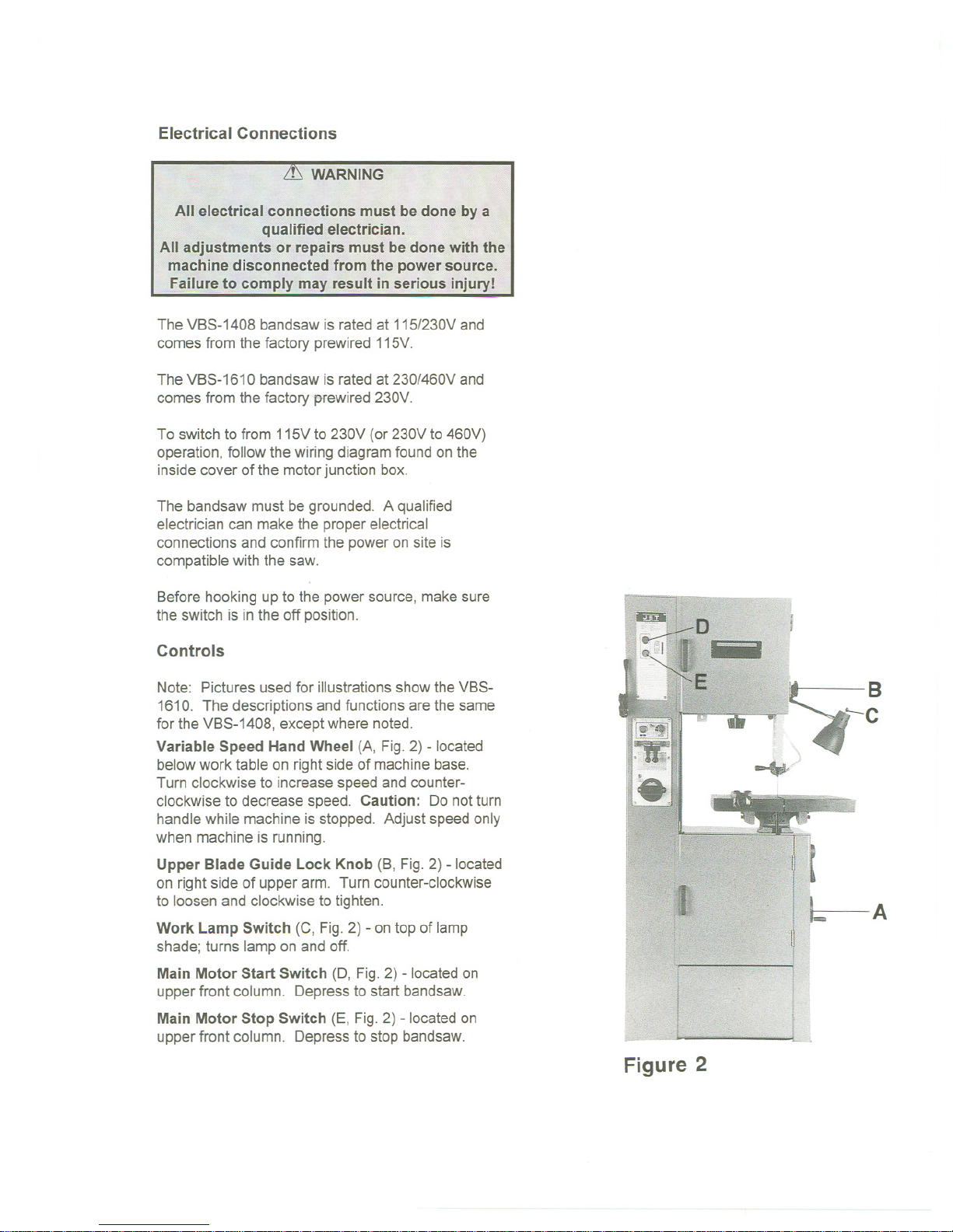
Controls
t
~
.
B
!
~
. "-C
~/J
Note: Pictures usedfor illustrationsshowthe VBS-
1610. The descriptions and functions are thesame
for the VBS-1408, exceptwhere noted.
Variable Speed Hand Wheel (A, Fig. 2) - located
belowwork table on rightside of machinebase.
Turn clockwise to increase speed and counter-
clockwise to decrease speed. Caution: Do not turn
handlewhile machineis stopped. Adjustspeed only
when machine is running.
Upper BladeGuide LockKnob (B, Fig.2) - located
on right side of upperarm. Turn counter-clockwise
to loosen and clockwiseto tighten.
A
Work Lamp Switch (C, Fig. 2) - on top of lamp
shade; turns lamp on and off.
Main Motor Start Switch (0, Fig. 2) - located on
upper front column. Depress to start bandsaw.
Main Motor Stop Switch (E, Fig. 2) - located on
upper front column. Depress to stop bandsaw.
Figure 2
Page 7

-- -- -
_u n- - _n_nn-
Gear Shift Lever (A, Fig. 3 - VBS-1610 only)-
located on the rightside of the base underthe table.
Move the lever towardthe front of the machineto
engage the low rangesetting. Movethe lever toward
the rear to engage the high rangesetting. Change
gears onlywhen the power is off. Turn variable
speed handwheelwhile changingspeed rangesto
help the gears engage.
Grinder Toggle Switch (B, Fig.3) - locatedon
bladewelder panelfound on columnfront. Flip
switch up to start grinder; flip down to stop grinder.
Weld Button (C, Fig. 3) - locatedon bladewelder
panelfound oncolumn front. Depressand holdto
start welding. Shutsoff automaticallywhen weld is
done. Releasewhen weld is completed.
Anneal Button (D, Fig. 3) - located on blade welder
panel found on column front. Depress and hold to
anneal blade, release to stop.
Blade Clamp Pressure Knob (E, Fig. 3) - located
on bladewelder panelfound oncolumnfront. Turn
counter-clockwise to bring blade clamps closer
together and clockwise to separate.
Blade Clamps (F, Fig. 3)- locatedon bladewelder
panelfound oncolumn front. DOWNpositionallows
insertionof blade into clamp. UP positionlocks
blade.
Blade Tension Handwheel (G, Fig.3) - locatedon
underside of upper frame. Turn clockwiseto tension
blade;counter-clockwise to releasetension on blade.
Shear Lever (H, Fig. 3) - locatedon uppercolumn.
UP positionallows insertion of blade end intoshear.
Pull lever DOWN to cut blade.
Blade Tension Indicator (I, Fig. 3- VBS-1610 only)
-located under the idlerwheel housingwith the
calibration scale visablefrom the rear of the
machine. Indicates bladetension relativeto the
width of the blade being used.
Table Tilt Mechanism - located under work table.
To tilt table left or right, loosen two hex cap screws
(A, Figure 4) at rear of mechanism. To level table
front to back, loosen four hex cap screws (A, Fig. 5)
on either side of mechanism.
-
H
Figure 3
Figure 4
Figure 5
Page 8
Adjustments
WARNING
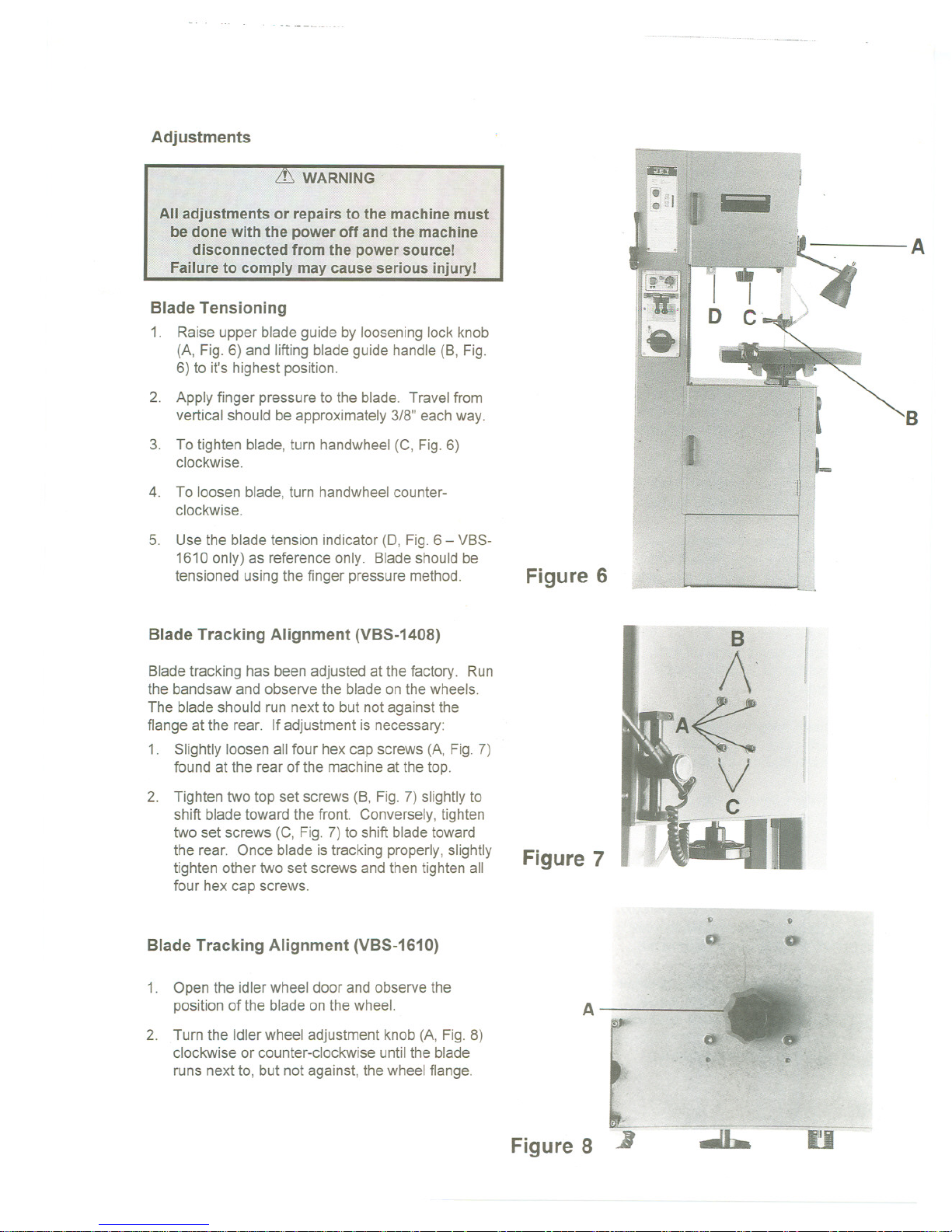
Blade Tensioning
1. Raise upper bladeguide by looseninglock knob
(A, Fig.6) and liftingblade guide handle (B, Fig.
6) to it's highestposition.
2. Apply finger pressure to the blade. Travel from
vertical should be approximately3/8" each way.
3. To tighten blade, turn handwheel (C, Fig. 6)
clockwise.
4. To loosen blade,turn handwheelcounter-
clockwise.
5. Use the bladetension indicator(0, Fig.6- VBS-
1610 only) as reference only. Bladeshould be
tensioned usingthe finger pressuremethod.
Blade Tracking Alignment (VBS-1408)
Bladetracking has been adjusted at the factory. Run
the bandsawand observe the bladeon thewheels.
The blade should run next to butnotagainstthe
flange at the rear. Ifadjustment is necessary:
1. Slightly loosen all four hexcap screws (A, Fig. 7)
found at the rear ofthe machineat the top.
2. Tighten two top set screws (8, Fig.7) slightlyto
shift blade toward the front. Conversely,tighten
two set screws (C, Fig. 7) to shift bladetoward
the rear. Onceblade is tracking properly,slightly
tighten other two set screws andthentighten all
four hex cap screws.
Blade Tracking Alignment (VBS-1610)
1. Open the idler wheeldoor and observethe
positionof the blade on the wheel.
2. Turn the Idlerwheel adjustment knob (A, Fig. 8)
clockwise or counter-clockwise untilthe blade
runs next to, but not against,thewheelflange.
Figure 6
Figure 7
Figure 8
.....................
A
B
!'
~O
"
.
A
-.
10
..L.
u
J
Page 9
n-- _n--- n n __n_n-_n-----
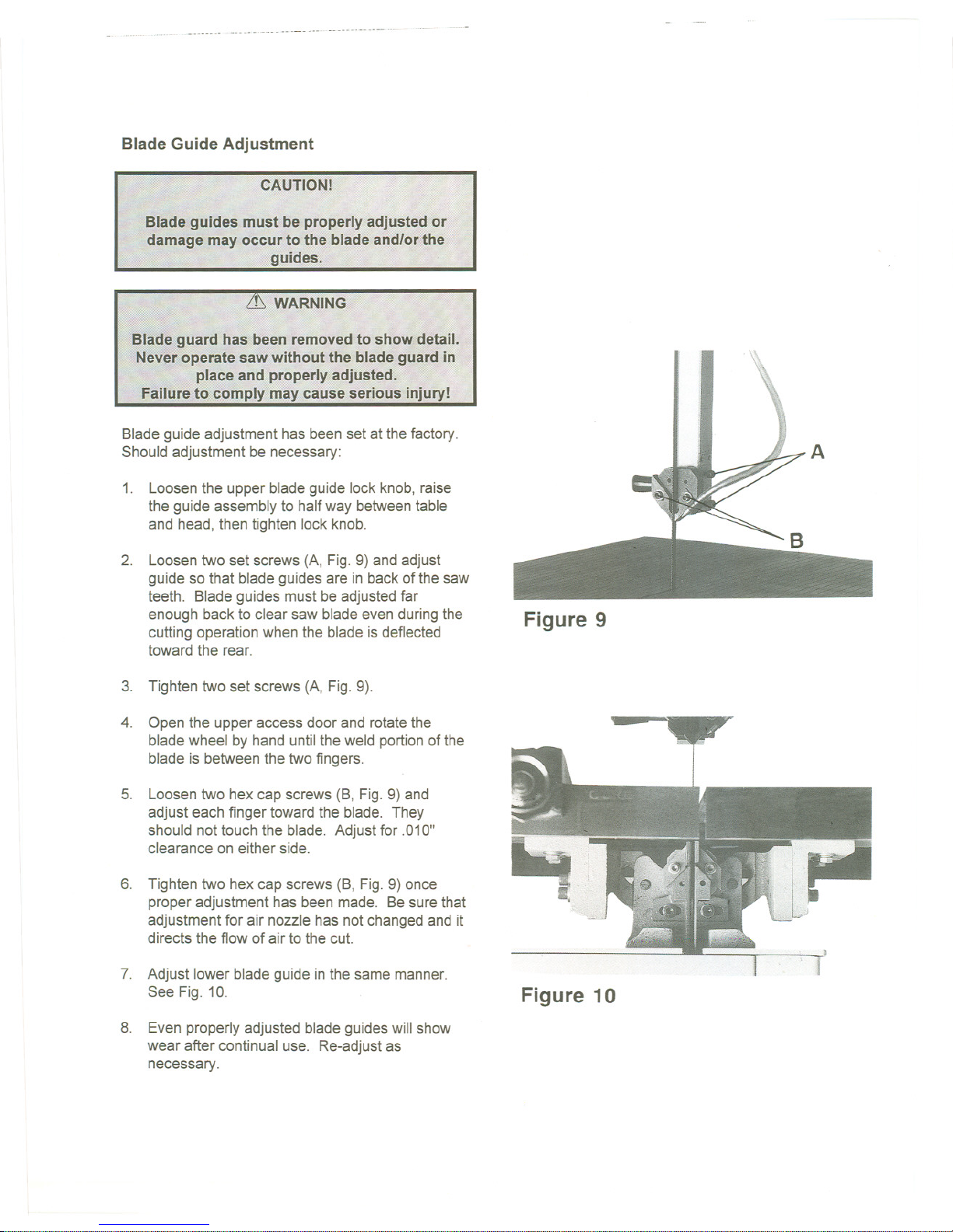
Blade Guide Adjustment
Blade guide adjustment has been set at the factory.
Should adjustment be necessary:
1. Loosenthe upper blade guide lockknob, raise
the guide assembly to half way betweentable
and head,then tighten lock knob.
2. Loosentwo set screws (A, Fig.9)and adjust
guide so that blade guides are in backof the saw
teeth. Bladeguides must be adjustedfar
enough backto clearsaw bladeevenduringthe
cutting operationwhen the blade isdeflected
toward the rear.
3. Tighten two set screws (A, Fig.9).
4. Open the upper access door and rotatethe
bladewheel by hand untilthe weld portionofthe
blade is between the twofingers.
5. Loosen two hexcap screws (B, Fig.9)and
adjust each finger towardthe blade. They
should not touch the blade. Adjustfor .010"
clearance oneither side.
6. Tighten two hexcap screws (B, Fig.9) once
proper adjustment has been made. Besure that
adjustmentfor air nozzle has not changedand it
directs the flow of airto the cut.
7. Adjust lower blade guide in the same manner.
See Fig. 10.
8. Even properly adjusted blade guides will show
wear after continual use. Re-adjustas
necessary.
Figure 9
Figure 10
Page 10
Top Guide Adjustment
Always positionthe top guide to within an 1/8"of the
top surface of the workpiece. This minimizes
exposure of the operator'shands to the saw blade.
Changing Saw Blades
1. Disconnectsaw from the powersource.
2. Move the upper bladeguide to its highest
position and lock in place.
3. Open bothwheel doors. Turn the tension
adjustment knob counter-clockwiseto loosen
tension onthe blade.
4. Removethe blade from bothwheels and
maneuver it aroundthe blade guard on the
column and protectiveshield on the upper blade
guide.
5. Install new blade by maneuveringaround blade
guard on the column and protective shieldon the
upper bladeguide.
6. Place it between the fingers of bothbladeguides
and onto both wheels. Positionnextto both
wheel flanges. Make sure teeth pointdown
toward the table.
7. Retention the saw blade byturningtensionhand
wheel. Rotatethe wheel by handand makesure
the blade is properly seated in the bladeguides.
Blade guideswill have to be adjusted if the
replacement blade is a different type and width.
8. Turn on the saw and check bladetracking.
Adjust tracking if necessary.
Blade Selection
Proper blade selection is just as important to band
saw operation as is blade speed and material feed.
Proper blade selection will impact blade life,
straightness of cut, cut finish, and efficiency of
operation. Excess blade breakage, stripping of
teeth, and waviness of cut are some of the results of
improper blade selection.
Blades are classified by material composition, tooth
shape, pitch of teeth, and type of set, gage of the
band material, and kerf of the set (width of cut).
Page 11

- ----
Material Composition
Carbon Steel - low cost, for use with non-ferrous
materials, wood, and plastics.
High Speed Steel - resistsheat generated by dry
cutting. Usedfor ferrous metalsand are more
expensive than carbon steel blades.
Alloy Steel - tough and wear resistant,cuts faster
with longer blade life. Usedon hard materials. More
expensive than carbon or highspeed steel.
Carbide Tipped - for cutting unusual materials such
as uranium, titanium, or beryllium. Very expensive.
Tooth Shape
Note: When cutting thin materials, the rule for blade
pitch is to have a minimum of two teeth engaging the
material being cut at all times.
Standard Tooth - generally usedto cut ferrous
metals, hard bronze, hard brass, andthin metals.
Skip Tooth - havebetter chip clearance (larger
gullet) and are used on softer, non-ferrous materials
such as aluminium, copper, magnesium,and soft
brass.
Hook Tooth - providesa chip breakerand has less
tendency to gum up insofter materials. Used in the
same materialsas skip tooth butcan befed faster
than standard or skip tooth blades.
Set Type
Straight Set - used for free cutting non-ferrous
materials; Le., aluminum, magnesium,plastics,and
wood.
Wavy Set - used on materials of varying thickness
(pipe, tubing, and structural shapes).
Raker Set - used in large cuts on thick plate and bar
stock where finish of cut is not as important as
speed.
Page 12

Gage
Blade gage is the thickness of material the blade
from which the blade is produced. The thicker the
material, the stronger the blade will be.
Kerf
Kerf isthe width of a cut. Kerfwillvary accordingto
set of blade teeth.
Blade Width
The thinner the blade,the tighter the minimumradius
of cut will be. Always usethewidest bladepossible
for thejob.
General rulesfor bladeselection:
.
Select coarser pitch blades for thicker or softer
material.
.
Selectfiner pitch blades for thinner or harder
material.
.
Use fine pitch blades to obtain a smooth finish.
.
Use coarse pitch blades to obtain faster cutting
speeds (thick material).
.
To prevent prematurebladewear, use the
fastest practical speed.
.
Adjust the feed rate to ensure continuous
cutting action.
.
Run the bandsaw with the blade centered in the
upper and lower guides and the guide fingers
adjusted as close as possible without touching
the blade or weld joint.
Page 13

Using the Blade Welder
Blade Shear and Blade Preparation
1.
The blade should be cut to the longest length
that machinewill accept.
2.
Put the handle in the upright position.
3.
Place the blade against the back of the square
cutting guide of the shear.
4.
Bring the handle down firmly to cut blade.
5.
Use the blade grinder to assure the bladeends
are flat, square, and smooth.
6.
With fine pitched blades, one or moreteeth from
each sidewill have to be removedby grinding so
that the cross section ofthe weld area is
uniform.
Welder Preparation
1.
Clean the welder jaws andthe lowerjaw
inserts.
Welding
1.
Turn pressure switch (A, Fig. 11) to the zero
position.
2.
Join blade ends together and locate union inthe
center betweentwo electrodes.
3.
Set pressure switch (A, Fig. 11) to blade width
according to the scale.
4.
Press weld button (B, Fig. 11). Do notrelease
until the weld has been completed.
Position of Cut Ael.tlve
to The Gullet of the
Teeth - Tooth G'ound Mee Consumed
1/2 To~oth ~ ~Off ~ ~BY Welding.
LULJ ---LJJU- --L::JrL:J
Position of Cut Ael.tlve 4 Pitch
:::~e:e GUII~ the 1-1/2 Teeth G'oUnd A'ee Con,umed
3/4 TOnnoth ~ ~ ~ !:"ay Welding.
:', ---1_11 lLJ - - -n-r:1
Po,'t'on of Cut Is In 6 Pitch
The Cen.., of the
Gullet. 2 Teeth Gmund A,ee Consumed
1TOO~O:_~~ : 10<ByWelding.
LJJlLJLJjLLJ --01[]
~':.s~~."3~'?e~to~~~"i;ve- BPitch
Teeth 2.1/2 Teeth G,ound Mee Co"sumed
1-1/4T~/4Teeth :-:1M Off ~Weld;ng.
LiJ~ - - --COLLJ - - UlLJ
10 Pitch
Follow these cutting and grinding instructions and the teeth wiJI be uniformly
spaced after the weld.
B
A
Figure 11
CLEAN BLADE ENDS
WHICH CONTACT WELDER JAWS.
AEMOVE DIRT, 01 L. SCALE
AND OXIDE.
" / GRIND OFF TEETH
~ /\ WITHIN WELDING AREA
GAIND HEAE
./
.y
/
/
f'
f:
c
If snips are used
to cut blade,
grind ends squ.'e
as shown.
Points to remember in preparing the blade for welding
Page 14

Annealing
1. Releasethe welded bladeand clamp it again
betweenthe front edge of the two jaws.
2. Annealing procedurewill dependon bladetype:
Carbon Steel Blades
1. Press and jog the annealing switch button until
the weld is a "dull cherry" to "cherry red" color.
2. Allow the bladeto cool slowly by decreasingthe
jogging frequency.
GOOO WELD
~
'NCORRECT TOOTH SPACING
WELD NOT IN CENTER OF GULLET TOOTH WHICH WAS NOT
-, ~REMOVED HAS JAMMED IN WELD,
Carbon Steel Hard Back Blades
1. Heatthe blade slowly untilthe weld becomesa
deep blue color.
WEAK, INCOMPLETE WELD
(BLOW.OUT HOLESI
2. Continue to heatbyjogging the anneal button
until the width of the bluecolor is one-halfthe
length of the bandexposed betweenthejaws.
3.
Do not overheat or the temper of the band will be
damaged. Caution - Do not heat beyond the
"blue" stage. If the band beginsto show any red
color, it is too hot. Cool quickly by releasingthe
anneal button.
!(~
;
:
I;',:.
;~
:;~1
:".T
DISTANCE BETWEEN JAWS
.'.
'.
,.
~"
.',
,'..
Bi-Metal Blades
Correct annealing of Carbon Steel Hard
Back Blades
1. Heatthe blade slowly byjogging the annealing
switch button until the weldjust beginsto emit
light (dull red color). Thedesirecolor maynot
always be visible in normal room light- always
shade the weld areawith your hand.
2. Cool the weld quickly by releasingthe annealing
button.
3. Follow this procedure before and after grinding
bimetal blades.
Page 15

Blade Grinding
After annealing,the blademust be groundto remove
excess metal or flash from the weld. With the teeth
facing out, grind theweld carefully. Do not hit the
teeth, grind deeper than the weld, burn,or overheat
the weld area. Besure to removeflash from the
back edge of the blade. Any flash or "stub" teeth
which project beyondthe normal set or heightof the
other teeth must be ground oft.
Secondary Annealing
Anneal the weld 2-3 times again after grinding.
Welder Clean-Up
It is important that the welder jaws bekeptclean at
all times. Thejaws and inserts mustbewiped or
scraped clean after every weld. Doingthiswill
ensure betterwelds by:
1. Holding proper alignment.
2. Preventing flashfrom becomingembeddedin
the blade.
3. Preventing shorts or poorelectricalcontact.
Lubrication Schedule
.
Upper Blade Guide Shaft -lightly grease
weekly. Clean after every day's use.
.
Speed Change Handle -grease monthly with
a light film on teeth and threads.
.
Variable Pulley - grease fitting using a light
weight grease found on end of pulley shaft.
.
Blade Tension Screw - grease monthly.
Good Grinding,
Bad Grinding,
I
J,..
1
} r \
}
I \
c=.r=::::J
Page 16

3;?
5140
5100
P3-1
~ 4150
9300
~
G6201
/
~
0
4030
401 \
9500
9590
79310
7430
VBS- 1408
Page 17

6810
6161
6071
/6120
9290~ \~.
~ (f 6070
Page 18

Parts List for the VBS-1408 Bandsaw
Index Part
No. No.
Description
Size
Qty.
1010 ....vBS1408-1010 , Work Table 1
1020 VBS14-102 Table Support Frame 1
1030 1030 Table Bracket(right) 1
1040 1040 Table Bracket (left) 1
1060 TS-0680061 Washer 1/2 2
1070 1070 Tube Screw 4
1090 1090 Table Support Housing 1
1100 1100 Guide Support Housing 1
1310 VBS16-131 Blade Guide Support 2
1320 VBS1220A-132 BladeGuide 2
1330 VBS16-133 BladeStopper : 2
1350 1350 Blade Guide PosL 1
1360 1360 Guide Post Housing 1
1361 1361 Guide Post Spring 1
1370 1370 Blade Guide (left) 1
1380 1380 Blade Guide (right) " 1
1390 1390 Post HoldingPin 1
VBS1610-BS BladeGuide Assembly Complete 1
1910 1910 Bushing(re:VBS1610-BS) 4
1920 1920 Lift(re:VBS1610-BS) , 1
1930 1930 Blade Shaft (re:VBS161O-BS) 1
1940 1940 Vaned Iron Plate(re:VBS1610-BS) 2
1950 1950 Lower Blade(re:VBS161O-BS) 2
1960 1960 UpperBlade (re: VBS1610-BS) 1
1970 1970 Joint Plate- Left (re: VBS1610-BS) 1
1980 1980 Chain Joint - Right (re:VBS1610-BS) 1
1990 1990 Handle Bar (re:VBS1610-BS) 1
2000 VBS14-009 Drive Motor 1
2010 VBS1408-2010 Motor Pulley 1
2020 2020 MotorSuspensionArm 2
2130 2130 ReducerPulley 8" 1
2300 2300 Speed Reducer 1
3010 VBS1408-3010 LowerWheel 1
3020 VBS14-302... RubberTire 2
3030 VBS1408-3030 TaperSleeve.. 1
3040 VBS1408-3040 Wheel Lock Nut 1
3050 VBS1408-3050 UpperWheel 1
3060 VBS1408-3060 UpperWheel Lock 1
3070 3070 UpperWheel Nut 1
3080 3080 Slide Block Housing 1
3090 VBS14-309 Slide Block SeaL 2
3100 3100 Slide Block Guide 2
3110 3110 UpperWheel Slide 1
3120 VBS1408-3120 Wheel Shaft , , 1
3121 3121 ......... Spring ... ...... ............ ... ... ...1
3150 3150 Washer 1
Page 19

vBS1610-AP Air PumpAssembly Complete 1
4010 4010 Air PumpHousing(re:VBS1610-AP) 1
4020 4020 PumpCover (re:VBS1610-AP) 1
4030 4030 PumpShaft (re:VBS1610-AP) 1
4040 4040 Air PumpPulley 1
4050 4050 Air PumpVein 4
4140 4140 Air Outlet (re: VBS161O-AP) 1
4150 4150 Air Inlet(re:VBS1610-AP)""'"'''''''''''''''''''''''' 1
4170 4170 Air Nozzle 1
4180 4180 Air NozzleClip 1
4190 4190 Air Tube 1
5000 VBS1408-5000 Main Body ... 1
5100 VBS1408-5100 Rear Door 1
5120 VBS1408-5120 LowerDoor.. .. 1
5140 VBS1408-5140 UpperDoor 1
6010 VBS14-601 Limit Switch 2
6011 6011 Insulator 1
6020 6020 Guide Block "'''''''''''''''''''''''''''''''' 1
6021 6021 Spring Bracket 1
6030 6030 GuideCasting 1
6040 6040 Housing 1
6050 6050 StationaryJaw 1
6051 6051 Insulator 1
6052 6052 InsulatorTube 3
6053 6053 InsulatorWasher 3
6054 6054 Spacer 3
6060 6060 EccentricShaft. 2
6070 6070 Clamp Lever(right) 1
6071 6071 Clamp Lever(left) 1
6100 6100 Clamp Support(right) 1
6101 6101 Clamp Support (left) 1
6110 6110 Clamp Plate(right) ... 1
6111 6111 Clamp Plate (left) 1
6120 6120 Cam 2
6130 6130 MovingJaw 1
6150 6150 Weld Button 1
6160 6160 Micro Switch 1
6161 6161 Bracket 1
6170 VBS16-617 PressureAdjust Knob 1
6180 VBS16-618 ...... Shaft ...... ....... 1
6200 VBS16-620 Cam.. 1
6210 VBS16-621 Weld TensionArm 1
6211 6211 Bushing 1
6220 6220 Spring (short)"'"'''''''''''''''''''''''''''''''''''''''''''''' 1
6230 6230 Spring (long) 1
6240 VBS14-624 Transformer .. 1
6241 6241 ... ...... """ MountingBracket .................. ...1
6250 VBS16-625 Switch... 1
6260 VBS14-626 Grinder Motor 1
6270 6270 Spacer 1
6280 ....JWG12-628 GrinderWheel 1
6281 TS-0680021 Washer 1/4 1
6282 TS-1540041 Hex Nut 6MM 1
6290 vBS16-629 GrinderGuard 1
Page 20

6291 6291 GrinderCover 1
6330 6330 Welder Nameplate 1
6340 6340 InstructionLabel 1
6350 6350 Grinder Label 1
6420 ....6420 AnnealSwitch , 1
6745 6745 Voltage Reducer 1
6799 6799 ...... ...Wiring Plate ... 1
VBS1610-WL Work LampAssembly Complete 1
6810 6810 Shield(re: VBS1610-WL) 1
6820 6820 Jointer (re: VBS161O-WL) 1
6830 6830 Brass Nut (reVBS1610-WL) 1
6840 6840 LampArm (re: VBS1610-WL) 1
6850 6850 Arm Jointer(re:VBS1610-WL) 1
6860 6860 Arm Tube(re: VBS161O-WL) 2
6870 6870 Tube Holder(re:VBS1610-WL) 1
6880 6880 Arm Nut (re: VBS161O-WL) 4
6890 6890 Tube Locker(re: VBS161O-WL) 2
6900 6900 : ArmHousingAdjuster(re:VBS1610-WL) 1
6910 6910 HousingAdjust Screw(re:VBS1610-WL) 1
6920 6920 LampArm Housing(re:VBS1610-WL) 1
6930 6930 .. Holder(re: VBS161O-WL) 1
6931 6931 Holder(re:VBS1610-WL) 1
6940 6940 Hex Nut (re:VBS1610-WL) 1
6950 6950 LampSocket (re:VBS1610-WL) 1
7400 VBS16-7400 Speed Change Shaft 1
7410 VBS16-7410 Shaft Block 1
7420 VBS16-7420 Speed IndicatingShaft 1
7430 VBS16-7430 Gear ShaftArm 1
7440 7440 IndicateGear ShaftArm 1
7450 VBS16-7450 Speed Shaft Housing 1
7451 VBS16-7451 " WasherTube 1
7460 VBS16-7460 Pulley ShaftArm 1
VBS1610-VP Variable PulleyAssembly Complete 1
7470 7470 Variable PulleyShaft * 1
7490 VB$16-7490 PulleyShaftHousing* 1
7500 VBS16-7500 lnner Pulley* 1
7510 VBS16-7510 MiddlePulley * " 1
7520 VBS16-7520 Outer Pulley* 1
8111 8111A Name Plate.. ... 1
8741 8741 Tilt Indicator(L&R) 1
8771 8771 Tilt Indicator(F&R) 1
9015 9015 " GuidePostBlock 1
9030 9030 HandWheel 1
9031 9031 HandWheel 1
9040 9040 Brass HandWheel (re: VBS1610-WL) 1
9210 9210 HandleKnob " 2
9230 9230 HandWheel Knob 1
9290 VBS14-609 ... Knob.... , 2
9300 9300 Upper Door Hinge 2
9310 9310 Hinge 4
9500 9500 Spring Plate :."'"'''''''''''''''''''''''''' 4
9590 9590 HandleArm : 3
9600 9600 Chip Stopper .. 1
9720 9720 Pointer 1
Page 21

6799.
6745
5140
4040
4170
6710
~
U 118712~ ~ 979
~~
3040 3010
9590
~
0/40 '0790
6720
6770
==
VBS-1610
Page 22

9780 9780 BrushBracket 1
9700 9700 Pointer 2
9790 9790 ChipBrush 1
9995 9995 Grease Nozzle 1
9999 9999 , EyeBolt... 1
A700 A700 Pointer 1
BA32 VB-A32 V-Belt. 1
BA36 VB-A36 V-Belt.. ., , 1
BH32 ...VB-M29 V-Belt 1
G6201.. BB-6201 BallBearing 2
G6205..BB-6205
BallBearing 2
P3-15... P3-15 On-OffSwitch 1
* included in VBS1610-VP Variable PulleyAssembly Complete
Page 23

Parts list for the VBS-161 0 Bandsaw
Index
No.
Part
No.
Description
Size
Qty.
.. VBS161O-GB Gear BoxAssembly Complete 1
0500 0500 Gear Box * '''''''''''''''''''''''''''''''''' 1
0510 0510 Gear Box Cover * 1
0520 0520 Gear* 1
0521 0521 Gear* 1
0530 0530 ScrewNut * 35MM 1
0540 ... 0540 Gear * 1
0550 0550 GearShaft * 1
0560 .. 0560 ShaftCover * 1
0570 0570 Gear * 1
0580 0580 MainShaft* 1
0590 0590 MainShaftCover* 1
0600 0600 Speed ChangingShaft * 1
0610 0610 Speed ChangingArm * 1
0611 0611'"'''''''''''''''''''''''''' Shaft Stopper * 1
0612 0612 Spring* " 1
0620 0620 SlideBlock*
, 1
0630 0630 Clutch* . 1
0631 0631 BrassBracket* " 2
0632 0632 Brass Bracket* "... 1
0700 0700 SpeedChangingLever 1
0740 0740 ""'''''''' ShaftHousing .." 1
0790 0790 SpeedLeverRing 1
1010 VBS1610-1020.... WorkTable """"""""""""""""" 1
1020 VBS14-102 Table SupportFrame 1
1030 1030 Table Bracket(right) 1
1040 1040 Table Bracket(left) 1
1060 TS-0680061 Washer.. 1/2 2
1070 1070 Screw Bushing 4
1090 1090 Table Support Housing 1
1100 1100 GuideSupportHousing ""'''''''''''''''''''''''''''''' 1
1310 VBS16-131 BladeGuideSupport 2
1320 VBS1220A-132 BladeGuide 4
1330 VBS16-133 BladeStopper 2
1350 1350 BladeGuide Post 1
1360 1360 Guide Post Housing """"""""""""'''''''''' 1
1361 1361 PostClamp Spring 1
1370 1370 BladeGuard (left) 1
1380 1380 BladeGuard (right) 1
1390 1390 PostHoldingPin"""""""""""'''''''''''''''''''''''' 1
1550 VBS16-155 Rip Fence "'''''''''''''''''''''''''''''''''''''''''''''''''''''' 1
VBS1610-BS Blade Shear Assembly Complete 1
1910 1910 Bushing (re:VBS1610-BS) , 1
1920 1920 Lift (re: VBS161 O-BS) """"""""""""""""'"'' 1
1930 1930 Blade Shaft (re: VBS1610-BS) , 1
1940 1940 Vaned Iron Plates (re: VBS1610-BS) """""'''' 1
1950 1950 Lower Blade (re: VBS1610-BS) , 2
1960 :..1960 Upper Blade(re:VBS1610-BS) 1
Page 24

1970 1970 Plate (re: VBS1610-BS) 1
1980 1980 Joint (re: VBS1610-BS) 1
1990 1990 Handle Bar (re: VBS1610-BS) 1
2000 VBS1610-2000 Main Drive Motor 1
2010 VBS161 0-201 0 Motor Pulley. 1
2020 2020 Motor Suspension Arm 2
2030 2030 Motor Spring Housing 1
2040 2040
MotorSpring 1
2050 2050 MotorSpringSupport 1
3010 VBS1610-3010 LowerWheel 1
3020 VBS16-302 RubberTire 2
3030 3030 Taper Sleeve 1
3040
VBS1610-3040 Wheel LockingNuL 1
3050 ...VBS16-305 Upper Wheel 1
3060 VBS14-306 UpperWheel Lock 1
3070 3070 UpperWheel Nut 1
3080 3080 Slide BlockHousing 1
3090 3090 Slide BlockSeal... 2
3100 3100 Slide BlockGuide 2
3110 3110 UpperWheelSlider 1
3111 3111 : Slide Cover 1
3113 3113 SlidePin , 1
3120 VBS1610-3120 Wheel ElevateShaft 1
3121 3121.. Spring .. 2
3150 3150 ...... Washer... , 1
3180 3180 IndicatingRing 3
3190 3190 Tension Indicator 1
3200 3200 WheelTiltAdjuster 1
3220 3220 WheelTilt Connector 1
3240 3240 ConnectorWasher 1
3250 3250 Connector Housing .., 1
VBS161 O-AP Air Pump Assembly Complete 1
4010 4010 AirPimp Housing(re:VBS1610-AP) 1
4020 4020 PumpCover(re:VBS1610-AP) 1
4030 4030 PumpShaft(re:VBS161O-AP) 1
4040 4040 Air Pump Pulley 1
4050 4050 Air PumpVane 4
4140 4140 : Air Outlet(re: VBS161O-AP) 1
4150 4150 Air Inlet (re: VBS1610-AP) 1
4170 4170 AirNozzle , 1
4180 4180 Air Nozzle Clip 1
4190 4190 AirTube : 1
5000 VBS1610-5000 Main Body 1
5100 VBS1610-5100 Rear Door 1
5120 VBS1610-5120 Lower Door 1
5140 VBS1610-5140 UpperDoor 1
6010 VBS14-601 LimitSwitch ... ... 2
6011 6011 Insulator 1
6020 6020 GuideBlock , 1
6021 6021 Spring Bracket 1
6030 6030 Guide Casting 1
6040 6040 Housing 1
6050 6050 StationaryJaw 1
6051. 6051.. Insulator 1
Page 25

6052 6052 InsulatorTube 3
6053 6053 InsulatorWasher. 3
6054 6054 Spacer 3
6060 6060 EccentricShaft 2
6070 6070 Clamp Lever(right) '''''''''''''''''''''''''''''''''' 1
6071 6071 ClampLever (left) 1
6100 6100 ClampSupport(right) 1
6101 6101 ClampSupport(left) 1
6110 6110 Clamp Plate (right) 1
6111 6111 Clamp Plate (left) 1
6120 6120 Cam 2
6130 6130 MovingJaw ... ... ... 1
6150 6150 Weld Button 1
6160 6160 MicroSwitch 1
6170 VBS16-617 PressureAdjust Switch ... 1
6180 VBS16-618........ ... Shaft 1
6200 VBS16-620 Cam 1
6210 VBS16-621 Weld TensionArm 1
6211 6211 Bushing 1
6220 6220 Spring(short) ., 1
6230 6230 Spring (long) 1
6240 VBS16-624 Transformer 1
6241 6241 MountingBracket.. 1
6250 VBS16-625 Switch 1
6260 VBS16-626 Grinder Motor 1
6270 6270 Spacer 1
6280 JWG12-628 GrinderWheel... ... 1
6281 TS-0680021 Washer 1/4 1
6282 TS-1540041 Nut 6MM""""'''''''''''''''''' 1
6290 VBS16-629 Grinder Guard 1
6291 6291 Grinder Cover 1
6330 6330 Welder Name Plate 1
6340 6340 InstructionPlate 1
6350 6350 Grinder Label 1
6420 6420 Anneal Switch 1
6600 6600 PushButton(on) .. '''''''''''''''''''''''''' 1
6602 6602 PushButton(off) 1
6710 6710 MagneticSwitch 1
6720 6720 OverloadStarter 1
6745 6745 Voltage Reducer 1
6770 6770 Wire Housing 1
6799 6799 Wiring Plate 1
VBS1610-WL Work LampAssembly Complete 1
6810 6810 Shield (re:VBS1610-WL) 1
6820 .. 6820 Jointer (re:VBS161O-WL).. 1
6830 6830 BrassNut (re: VBS1610-WL) 1
6840 6840 LampArm (re:VBS1610-WL) 1
6850 6850 Arm Jointer(re:VBS1610-WL) 1
6860 6860 Arm Tube (re:VBS161O-WL) 2
6870 6870 Tube Holder(re:VBS1610-WL) 1
6880 6880 Arm Nut(re:VBS1610-WL) 1
6890 6890 Tube Locker(re: VBS1610-WL) 1
6900 6900 Arm HousingAdjuster(re:VBS1610-WL) 1
6910 6910 HousingAdjustScrew(re:VBS1610-WL) 1
Page 26

6920 6920 LampArm Housing (re:VBS1610-WL) 1
6930 6930 Holder (re:VBS1610-WL) 1
6931 6931 Holder (re:VBS1610-WL) 1
6940 6940 Hex Nut(re:VBS1610-WL) 1
6950 6950 Lamp Socket (re: VBS1610-WL) 1
7070 7070 Pulley 1
7400 VBS16-7000 VariablePulleyShaft 1
7410 VBS16-7410 Shaft Block 1
7420 VBS16-7420 Speed IndicateShaft 1
7430 VBS16-7430 Gear Shaft Arm 1
7440 7440 IndicateGear ShaftArm 1
7450 VBS16-7450 Speed Shaft Housing 1
7451 VBS16-7451 WasherTube 1
7460 VBS16-7460 PulleyShaftArm 1
VBS1610-VP ,Variable PulleyAssemblyComplete 1
7470 VBS16-7470 VariablePulleyShaft ** 1
7490 VBS16-7490 PulleyShaft Housing** 1
7500 VBS16-7500 Pulley (inner) ** 1
7510 VBS16-7510 Pulley(middle)** 1
7520 VBS16-7520 Pulley (outer) ** 1
8092 8092 LubricationPlate 1
8111 8111A NamePlate 1
8712 8712 IndicatorPlate 1
8741 8741 Tilt Indicator(left and right) 1
8771 8771 Tilt Indicator(front and back) """"""""""""'''''''''' 1
9013 9013 Rip Fence Lock Knob 1
9015 9015 GuidePost Lock 1
9040 9040 Brass HandWheel (re: VBS1610-WL) 1
9060 9060 Tilt Adjust HandWheel 1
9070 9070 HandWheel 1
9031 9031 HandWheel 1
9210 9210 ......... ... Knob ............ .... 1
9220 9220 Lever Knob 1
9230 9230 Hand Wheel Knob 1
9240 9240 Washer " 1
9290
VBS14-609 Knob , ."'"'''''''''''''''' , 2
9300 9300 UpperDoor Hinge 2
9310 9310 Hinge ... 4
9500 9500 SpringPlate 4
9590 9590 , HandleArm 2
9600 9600 ChipStopper 1
9700 9700 Indicate Pointer 2
9720 9720 Speed Pointer 1
9780 9780 BrushBracket 1
9790 9790 ChipBrush 1
9995 9995 , GreaseNozzle 1
9999 9999 Eye Bolt 1
B3320 VB-B22 V-Belt 1
B3520. VB-B52 V-Belt ... 1
BM36 VB-M36 V-Belt 1
G6008 BB-6008 BallBearing 1
G6201 BB-6201 BallBearing 2
G6206 BB-6206 BallBearing 1
G6205 BB-6205 , Ball Bearing 2
Page 27

G6303 BB-6303... Ball Bearing 1
G6306 BB-6303 Ball Bearing 1
G6304 BB-6304 Ball Bearing 1
* Includedin VBS1610-GBGear BoxAssemblyComplete
** Included in VBS1610-VPVariablePulleyAssembly Complete
Page 28

VBS-1408
~
PB3:Weld Button Switch
PB4:Anneal Button Switch
LS1: Weld Automatic Stop Switch
SWl Grinder On-Off Switch
SW2:Welder Lamp On-Off Switch
PBl
oh
I
I
I
I
I
I
i..
0
0
~
110
7 220
8
SW2
110
PB3
Welder
LSl
1 .
!
2
3
4
PB4
my
c
230Y
-
2
N
E
C
T
Page 29

VBS- 161 0
R
S
T
E
l
PB1: Saw Stop Button Switch
PB2:Saw Start Button Switch
PB3:Weld Button Switch
PB4:Anneal Button Switch
LS1: Weld Auto Stop Switch
SWl: Grinder On-Off Switch
SW2:WorkLamp Switch
230V C 460V
- ~ 0
I ~< I N
1112131~IUIV w N 11121314~lll
E
-¥-.
A
A
10
1 1
12
13
14
15
220
PB4
16
17
18
0
110
SW2
2
3
4
Welder
5
Page 30

NOTE
Page 31

NOTE
Page 32

 Loading...