

Page 1
Operating Instruct i ons and Parts Manual
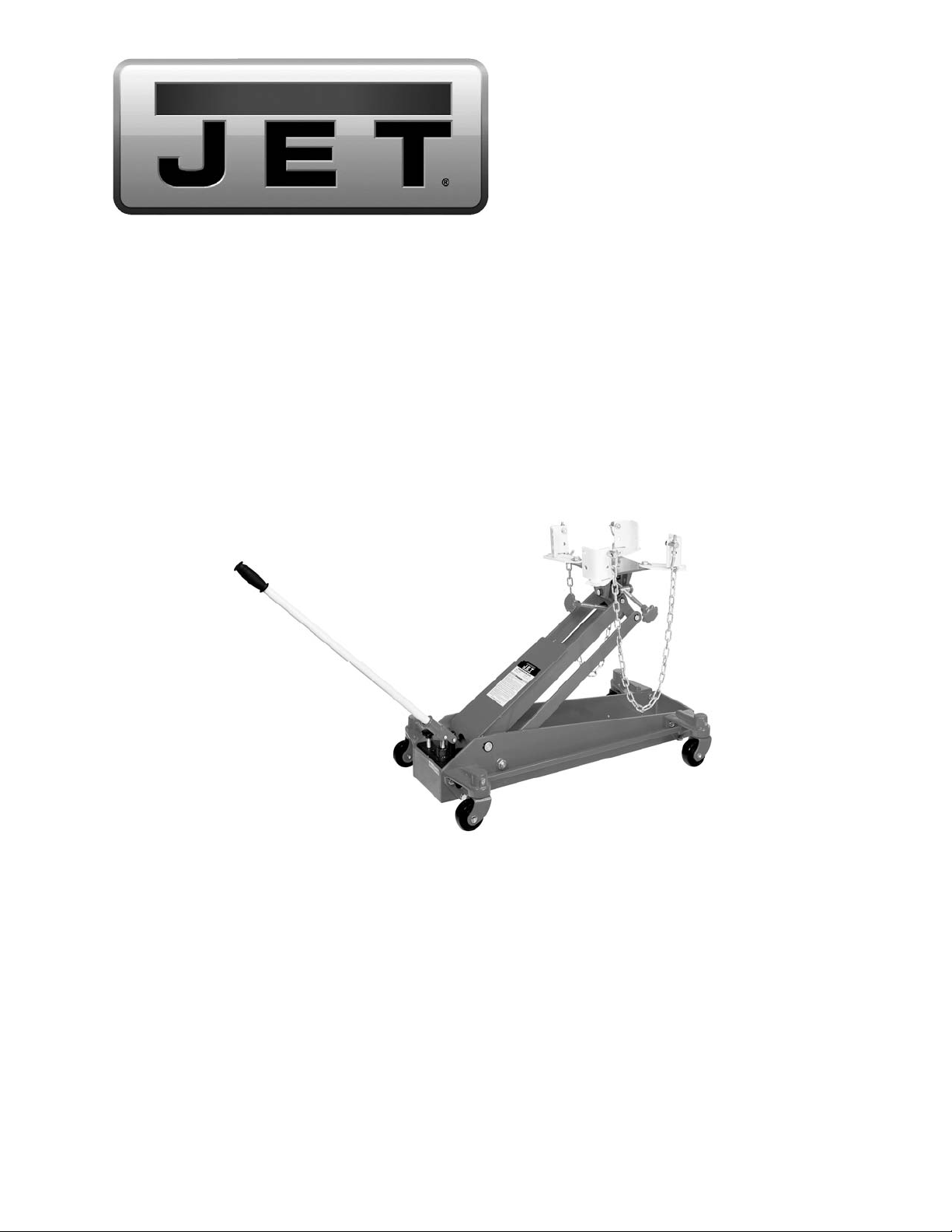
Transmission Jack
Model TJ-2000X
JET
427 New Sanford Road
LaVergne, Tennessee 37086 Part No. M- 450077
Ph.: 800-274-6848 Revision C1 05/2014
www.jettools.com Copyright © 2014 JET
1
Page 2

Warranty and Service
JET warrants every product it sells against manufacturers’ defects. If one of our tool s needs service or repair,
please contact Technical Service by calling 1-800-274- 6846, 8AM to 5PM CST, Monday through Friday.
Warranty Period
The general warranty l ast s for the time period specified in the li t eratur e incl uded with your pr oduct or on the official
JET branded website.
• JET products carry a limited warranty whi ch var ies in duration based upon the product. (See chart below)
• Accessories carry a limi t ed warranty of one year from the date of receipt.
• Consumable items ar e defined as expendable parts or accessories expected to become inoperable within a
reasonable amount of use and are covered by a 90 day limited warranty agai nst manufacturer’s defects.
Who is Covered
This warranty covers only the initial purchaser of the product fr om the date of delivery.
What is Covered
This warranty covers any defects in workmanshi p or materials subject to the limit at i ons stated below. This warranty
does not cover failures due directly or indirectly t o misuse, abuse, negligence or accidents, normal wear-and-tear,
improper repair, alterations or lack of maintenance.
Warranty Limit a t i ons
Woodworki ng pr oduct s with a Five Year Warranty t hat are used for commercial or industrial pur poses default t o a
Two Year Warranty. Pl ease contact Technical Service at 1-800-274- 6846 for further clarification.
How to Get Technical Suppor t
Please contact Technical Service by calling 1-800-274-6846. Pl ease not e t hat you will be asked to provide proof
of initi al pur chase when calling. If a product r equires furt her inspecti on, t he Technical Service representative will
explain and assist with any additional action needed. JET has Authorized Service Centers located throughout the
United States. For the name of an Authori zed Service Center in your area call 1-800-274-6846 or use the Service
Center Locator on the JET website.
More Information
JET is constantly addi ng new products. For complete, up-to-date product i nf or mation, check with your l ocal
distributor or visit the JET website.
How State Law Applies
This warranty gives you specific l egal rights, subject to appli cable state law.
Limitations on This Warranty
JET LIMITS AL L IMPLIED WARRANTIES TO THE PERIOD OF THE LIMITED WARRANTY FOR EACH
PRODUCT. EXCEPT AS STATED HEREIN, ANY IMPLIED WARRANTIES OF MERCHANTABILITY AND FITNESS
FOR A PARTICULAR PURPOSE ARE EXCL UDED. SOME STATES DO NOT ALLO W LIMITATIONS ON HO W
LONG AN IMPLIED WARRANTY LASTS, SO THE ABOVE LI MI TATION MAY NOT APPLY TO YO U.
JET SHALL IN NO EVENT BE LIABLE FOR DEATH, INJ URIES TO PERSONS OR PRO PERTY, OR FOR
INCIDENTAL, CONTINGENT, SPECIAL, OR CO NSEQUENTIAL DAMAGES ARISING FROM THE USE OF O UR
PRODUCTS. SOME STAT ES DO NOT ALLOW THE EXCLUSIO N OR LIMITATI ON OF INCI DENTAL O R
CONSEQUENTIAL DAMAG ES, SO THE ABOVE LIMITATION OR EXCLUSI ON MAY NOT APPLY TO YOU.
JET sells through distributors only. The specificat i ons listed in JET printed m at erials and on official JET website are
given as general informati on and ar e not bi ndi ng. JET r eserves the right to effect at any time, without pr ior notice,
those alterations to parts, fitti ngs, and accessory equipm ent which t hey m ay deem necessary for any reason
whatsoever. JET
Product Listi ng with Warranty Period
90 Days – Parts; Consumable item s; Light-Duty Air Tool s
1 Year – Motors; Machine Accessories; Heavy-Duty Air Tools; Pro- Duty Air Tools
2 Year – Metalworking Machinery; Electric Hoists, Electric Hoi st Accessories; Woodworking Machinery
used for industrial or commercial pur poses
5 Year – Woodworking Machinery
Limi t ed Lifeti me – JET Parallel clam ps; VO LT Series Electric Hois t s; Manual Hois t s; Manual Hoist
Accessories; Shop Tools; War ehouse & Dock products; Hand Tools
NOTE: JET is a divi sion of JPW Indust ries, Inc. References in this document to JET also apply t o JPW Indust ries,
Inc., or any of i t s successors i n i nt erest to the JET brand.
®
branded products are not sold in Canada by JPW Industries, Inc.
2
Page 3

Safety warnings
• Read and understand all operating instructions before use.
• The vehicle must be properly supported and blocked before starting repai rs.
• Use a transmission jack of the proper si z e and capacity t o handl e t he anticipated load. This
jack is rated f or a maximum load of 2,000 lbs. Do no t overload b eyond the jack’s rated
capacity. Overloading may cause damag e t o or failure of the j ack.
• Keep hand s, fingers, and arms away from moving p art s of the jack at all times.
• Secure the l oad with t he safety chain before lowering o r moving the load.
• Lower the load slowly and avoid sudden starts or stops that may cause the load to shift.
• Thi s jack is desig ned for use only on hard, level surfaces capable of sustaining the load.
Use on other than hard , level surfaces can result in jack instab ility and possible loss of
load.
• Do not use the transmission jack i f under the influence of alcohol or drugs.
• Thi s t r ansmission jack is desig ned and i ntended f or use by properly trained and
experienced personnel only. If you are not familiar with the proper and safe operation of a
transmission jack, do not use until proper training an d knowl edge have been obtained.
• The u se of this j ack is limited to the remo val, installation, and transportation in the lowered
position, of transmissions and differentials.
• Failure to comply with all of these w arnings may cause loss of load, damag e t o the jack,
and/or f ailure of the jack resulting in serious in jury and/or property damage.
3
Page 4

Specifications
Model Number ......................................................................................................................................... TJ-2000X
Stock Number ............................................................................................................................................. 450077
Capacity ................................................................................................................................................... 2,000 lbs.
Minimum Height.............................................................................................................................................. 8-1/2”
Maximum Height........................................................................................................................................... 30-1/2"
Sideways Adjustment L/R ........................................................................................................................... 30°/30°
Forward/Backward Tilt.......................................................................................................... ....................... 60 °/17°
Saddle Size ....................................................................................................................................... 7-3/4” x 7-3/4”
Base Size (LxW) ....................................................................................................................................... 35" x 19”
Net Weight .................................................................................................................................................. 175 lbs.
Shipping Weight .......................................................................................................................................... 184 lbs.
The specificati ons i n this manual ar e giv en as general informati on and ar e not binding. J E T reserves the
right to eff ec t, at any time and without prior notice, changes or alt er ations to parts, fittings, and accessory
equipment deemed necessary for any reason whatsoever.
4
Page 5

Assembly
4. Adjust the angle screws (75 & 88) to align with
the sh ape of the transmission.
All numbers in parenthesis ( ) refer to the index
number from the parts breakdown.
1. Mount the four angle brackets (100) to the
saddle (94) using four hex cap screws (102),
and four washers (101).
2. Insert four hook guides (91) into the angle
bracket holes and tighten using four washers
(96) and four hex nuts (95).
3. Place two chain screws (90) through hook
guides and thread in to chain connectors (92).
4. Thread hex nut (98) part way up the chain hook
(99) followed by a washer (97). Place through
hook guides and attach with washer (91), and
hex nut (98). Repeat for second chain hook.
5. Screw pump handle (2) into handle socket (5).
6. Turn gear (32) clockwise to close the pump
release valv e. Pump handle up and down to lift
the whole stroke. Turn gear (31) counterclockwise for lowering. Test jack raising and
lowering operation several times before use.
5. Adjust angle brackets (100) and chain (93) to
secure the transmission on the saddle. Tighten
hex cap screws (102).
6. Remove the transmission from the vehicle.
7. Turn gear (32) counter-clockwise slowly to
lower the saddle. Always lower the saddle
slowly. Always transport the load in the
lowered position with the chains securely
fastened.
8. Reverse this procedure when mounting the
transmission.
Maintenance
1. The hydraulic cylinder assembly contains
hydraulic fluid that must be kept at
approximately 80% of f ull at all times for proper
operation. To check the level and to fill,
remove screw (26).
2. Fill with clean hydraulic fluid only.
3. Replace the screw.
Operation
All numbers in parenthesis ( ) refer to the index
number from the parts breakdown.
1. Move the jack into position.
2. Turn the gear (32) clockwise fully to close the
valve.
3. Move the pump lever (2) up and down to raise
the saddle.
Lubrication
1. Lubricate the shaft threads of the angle screw
assembly (75 & 88) with #2 tube grease when
necessary.
2. Lubricate grease fitting (78) once every three
months, depending on usage, with #2 tube
grease.
5
Page 6

JET TJ-2000X Transmission Jack – Exploded View
6
Page 7

JET TJ-2000X Transmission Jack – Exploded View
Index No. Part No. Descriptio n Size Quanti ty
1 ................ TJ2000X-1................. Handle Grip .............................................................. ...................................... 1
2 ................ TJ2000X-2................. Pump Handle ........................................................... ...................................... 1
3 ................ TJ2000X-3................. Pin ............................................................................ 10x30 ............................ 1
4 ................ TJ2000X-4................. Pin ............................................................................ 10x30 ............................ 1
5 ................ TJ2000X-5................. Socket ...................................................................... ...................................... 1
6 ................ TJ2000X-6................. Snap Ring ................................................................ 9 .................................... 1
7 ................ TJ2000X-7................. Plunger..................................................................... ...................................... 1
8 ................ TJ2000X-8................. Wiper * .................................................................... ...................................... 1
9 ................ TJ2000X-9................. Back-up Rin g * ........................................................ Φ20x1 ............................ 1
10 .............. TJ2000X-10............... O-ring * ................................................................... 14x2.65 ......................... 1
11 .............. TJ2000X-11............... Pump ....................................................................... ...................................... 1
12 .............. TJ2000X-12............... Pump Seat ............................................................... ...................................... 1
13 .............. TJ2000X-13............... Seal Ring ................................................................. Φ22x1.5 ......................... 1
14 .............. TJ2000X14 ................ Screw ....................................................................... M10x1 ........................... 1
15 .............. TJ2000X-15............... Spring ...................................................................... 6x 25 .............................. 1
16 .............. TJ2000X-16............... Ball ........................................................................... 6 .................................... 5
17 .............. TJ2000X-17............... Screw ....................................................................... M 10x1 ........................... 1
18 .............. TJ2000X-18............... O-ring * ................................................................... 7.5x2.65 ........................ 2
19 .............. TJ2000X-19............... Spring ...................................................................... 7x 19.6 ........................... 1
20 .............. TJ2000X-20............... Screw ....................................................................... M 10x20 ......................... 1
21 .............. TJ2000X-21............... Seal Ring ................................................................. 10 .................................. 1
22 .............. TJ2000X-22............... Spring ...................................................................... 6x 25 .............................. 1
23 .............. TJ2000X-23............... Screw ....................................................................... M 12x20 ......................... 1
24 .............. TJ2000X-24............... Seal Ring ................................................................. Φ19x2 ............................ 1
25 .............. TJ2000X-25............... Ball ........................................................................... 9 .................................... 1
26 .............. TJ2000X-26............... Screw ....................................................................... M 10x1 ........................... 2
27 .............. TJ2000X-27............... O-ring * ................................................................... 19x2 .............................. 2
28 .............. TJ2000X-28............... Screw ....................................................................... M 10x1 ........................... 1
29 .............. TJ2000X-29............... Spring ...................................................................... 7.5x19.7 ........................ 1
30 .............. TJ2000X-30............... Ball Seat .................................................................. ...................................... 1
31 .............. TJ2000X-31............... Ball ........................................................................... 4 .................................... 1
.................. TJ2000X-32A ............ Knob Assembly (includes index # 18, 32, 33 and 34)...................................... 1
32 .............. TJ2000X-32............... Knob ........................................................................ ...................................... 1
33 .............. TJ2000X-33............... Pin ............................................................................ Φ2x20 ............................ 1
34 .............. TJ2000X-34............... Release Rod ............................................................ ...................................... 1
35 .............. TJ2000X-35............... Valve Block Assembly.............................................. ...................................... 1
36 .............. TJ2000X-36............... Caster Assembly ...................................................... ...................................... 4
37 .............. TJ2000X-37............... Reservoir.................................................................. ...................................... 1
38 .............. TJ2000X-38............... O-ring * ................................................................... Φ19x2.65 ....................... 1
39 .............. TJ2000X-39............... Ram Assembly......................................................... ...................................... 1
40 .............. TJ2000X-40............... Retaining Ring * ...................................................... Φ27x1.25 ....................... 1
41 .............. TJ2000X-41............... O-ring * ................................................................... Φ28x3 ............................ 1
42 .............. TJ2000X-42............... Y-ring * .................................................................... Φ30x6.3 ......................... 1
43 .............. TJ2000X-43............... Retaining Ring.......................................................... 32 .................................. 1
44 .............. TJ2000X-44............... Washer .................................................................... Φ38x1.5 ......................... 1
45 .............. TJ2000X-45............... O-ring * ................................................................... 33.2x4.6 ........................ 1
46 .............. TJ2000X-46............... Retainin g O-ring ....................................................... 42x6 .............................. 1
47 .............. TJ2000X-47............... Bushi ng .................................................................... 42x20 ............................ 1
48 .............. TJ2000X-48............... Piston Rod ............................................................... ...................................... 1
49 .............. TJ2000X-49............... O-ring * ................................................................... 50.5x2.4 ........................ 1
50 .............. TJ2000X-50............... Cylinder .................................................................... ...................................... 1
51 .............. TJ2000X-51............... Seal Ring * .............................................................. 76x2 .............................. 2
52 .............. TJ2000X-52............... Cylinder Nut ............................................................. ...................................... 1
53 .............. TJ2000X-53............... O-ring * ................................................................... 37.5x3.55 ...................... 1
54 .............. TJ2000X-54............... Wiper * .................................................................... 46x6 .............................. 1
55 .............. TJ2000X-55............... Split Pin .................................................................... 5x45 .............................. 1
56 .............. TJ2000X-56............... Link Rod ................................................................... ...................................... 1
57 .............. TJ2000X-57............... Side Plate ................................................................ ...................................... 1
7
Page 8

Index No. Part No. Descriptio n Size Quanti ty
58 .............. TJ2000X-58RF .......... Caster Seat Right Front ........................................... ...................................... 1
.................. TJ2000X-58RR ......... Caster Seat Right Rear (pump end) ........................ ...................................... 1
.................. TJ2000X-58LR .......... Caster Seat Left Rear (pump end)........................... ...................................... 1
.................. TJ2000X-58LF .......... Caster Seat Left Front ............................................. ...................................... 1
59 .............. TJ2000X-59............... Lock Washer ............................................................ 12 .................................. 2
60 .............. TJ2000X-60............... Screw ....................................................................... M 12x40 ......................... 2
61 .............. TJ2000X-61............... Screw ....................................................................... M 10 ............................... 6
62 .............. TJ2000X-62............... Thrus t Bearing.......................................................... 8205 .............................. 4
63 .............. TJ2000X-63............... Nut ........................................................................... M16 ............................... 2
64 .............. TJ2000X-64............... Lock Washer ............................................................ 16 .................................. 2
65 .............. TJ2000X-65............... Screw ....................................................................... M 8x12 ........................... 4
66 .............. TJ2000X-66............... Slot........................................................................... ...................................... 2
67 .............. TJ2000X-67............... Screw ....................................................................... M 6x12 ........................... 4
68 .............. TJ2000X-68............... Long Link Rod .......................................................... ...................................... 2
69 .............. TJ2000X-69............... Snap Ring ................................................................ 16 .................................. 4
70 .............. TJ2000X-70............... Spacer ..................................................................... 22x15 ............................ 2
71 .............. TJ2000X-71............... Short Link Rod ......................................................... ...................................... 2
72 .............. TJ2000X-72............... Nut ........................................................................... M10 ............................... 2
73 .............. TJ2000X-73............... Thrus t Bearing.......................................................... 8100 .............................. 3
74 .............. TJ2000X-74............... Guide Axle ............................................................... ...................................... 1
75 .............. TJ2000X-75............... Screw Assy .............................................................. M14X221 ...................... 1
76 .............. TJ2000X-76............... Snap Ring ................................................................ 20 .................................. 4
77 .............. TJ2000X-77............... Snap Ring ................................................................ 25 .................................. 2
78 .............. TJ2000X-78............... Grease Fitting .......................................................... ...................................... 1
79 .............. TJ2000X-79............... Shaft Arm................................................................. ...................................... 1
80 .............. TJ2000X-80............... Lifting Arm Assembly ............................................... ...................................... 1
81 .............. TJ2000X-81............... Axle .......................................................................... ...................................... 1
82 .............. TJ2000X-82............... Retaining Ring.......................................................... 18 .................................. 2
83 .............. TJ2000X-83A ............ Axle .......................................................................... ∅25x88 .......................... 1
84 .............. TJ2000X-84............... Saddle Base ............................................................ ...................................... 1
85 .............. TJ2000X-85............... Axle .......................................................................... ...................................... 1
86 .............. TJ2000X-86............... Snap Ring ................................................................ 18 .................................. 4
87 .............. TJ2000X-87............... Axle .......................................................................... ...................................... 1
88 .............. TJ2000X-88............... Screw Assy .............................................................. ...................................... 1
89 .............. TJ2000X-89............... Axle .......................................................................... ...................................... 1
90 .............. TJ2000X-90............... Chain Screw ............................................................ ...................................... 2
91 .............. TJ2000X-91............... Hook Guide .............................................................. ...................................... 4
92 .............. TJ2000X-92............... Chain Connector ...................................................... ...................................... 2
93 .............. TJ2000X-93............... Chain........................................................................ ...................................... 2
94 .............. TJ2000X-94............... Saddle...................................................................... ...................................... 1
95 .............. TJ2000X-95............... Hex Nut .................................................................... M10 ............................. 10
96 .............. TJ2000X-96............... Washer .................................................................... 10 .................................. 4
97 .............. TJ2000X-97............... Washer .................................................................... 8 .................................... 8
98 .............. TJ2000X-98............... Nut ........................................................................... M8 ................................. 8
99 .............. TJ2000X-99............... Chain Hook .............................................................. ...................................... 1
100 ............ TJ2000X-100............. Containi ng Angle ...................................................... ...................................... 4
101 ............ TJ2000X-101............. Washer .................................................................... 12 .................................. 4
102 ............ TJ2000X-102............. Screw ....................................................................... M12x 20 ......................... 4
103 ............ TJ2000X-103............. Bolt........................................................................... Φ22x40 .......................... 2
104 ............ TJ2000X-104............. Lock Washer ............................................................ 10 ................................ 12
105 ............ TJ2000X-105............. Screw ....................................................................... M10x 35 ......................... 6
106 ............ TJ2000X-106............. Hex Cap Screw ........................................................ ...................................... 1
107 ............ TJ2000X-107............. Hex Nut .................................................................... ...................................... 1
108 ............ TJ2000X-108............. Washer .................................................................... ...................................... 1
.................. TJ2000X-109............. Piston Packi ng Set (incls. 40-48) ............................. ........................................
.................. TJ2000X-PA .............. Pump Assembly (incls. 7-35, 37-54) ........................ ........................................
.................. TJ2000X-PRK ........... Pump Repair Kit (incls. 8-10, 18, 27, 38, 40-42, 45, 49, 51, 53, 54) .................
* indicates included in pump repair kit
8
 Loading...