

Page 1
.JET
EQUIPMENT &TOOLS
OPERATOR'S MANUAL
TAK-13GH/BD TAPER ATTACHMENT
.lET EcaUIPMENT a TOOLS, INC.
AW-H .WalterMeierHoldingCompany
NO. M-321442
Page 2

Page 3
-
Important Information
-
1 YEAR
LIMITEDWARRANTY
REPLACEMENT PARTS
Replacement parts for this tool are availabledirectlyfrom JET Equipment & Tools.
To placean order call 1-800-274-6844. Please have the following information ready:
1. Visa, MasterCard or DiscoverCard number
? Expirationdate
3. Partnumber listed within this manual
4. Shippingaddress other than a Post Office box
REPLACEMENT PARTS WARRANTY
JET Equipment&Tools makes every effortto assurethat parts meet high quality and dura-
bility standards and warrants to the original retail consumer/purc~aserof our parts that each
such part(s) be free from defects in materials andworkmanshipfor a period of thirty (30)
days from the date of purchase.
PROOF OF PURCHASE
Please retain your dated sales receipt as proof of purchaseto validate the warranty period.
JET offers a one year
warranty on all products
LIMITED TOOL AND EQUIPMENT WARRANTY
JET makes every effort to assure that its products meet high quality and durability standards and warrants to the
original retail consumer/purchaser of our products that each product be free from defects in materials and
workmanship as follows: 1 YEAR LIMITED WARRANTY ON ALL JET PRODUCTS. Warranty does not apply to
defects due directly or indirectly to misuse, abuse, negligence or accidents, repairs or alterations outside our
facilities or to a lack of maintenance. JET LIMITS ALL IMPLIED WARRANTIES TO THE PERIOD SPECIFIED
ABOVE FROM THE DATE THE PRODUCT WAS PURCHASED AT RETAIL. EXCEPT AS STATED HEREIN.
ANY IMPLIED WARRANTIES OR MERCHANTABILITY AND FITNESS ARE EXCLUDED. SOME STATES DO
NOT ALLOW LIMITATIONS ON HOW LONG THE IMPLIED WARRANTY LASTS, SO THE ABOVE LIMITATION
MA Y NOT APPLY TO YOU. JET SHALL IN NO EVENT BE LIABLE FOR DEATH, INJURIES TO PERSONS
OR PROPERTY OR FOR INCIDENTAL, CONTINGENT. SPECIAL OR CONSEQUENTIAL DAMAGES ARISING
FROM THE USE OF OUR PRODUCTS. SOME STATES DO NOT ALLOW THE EXCLUSION OR LIMITATION
OF INCIDENTAL OR CONSEQUENTIAL DAMAGES, SO THE ABOVE LIMITATION OR EXCLUSION MAY
NOT APPLY TO YOU. To take advantage of this warranty. the product or part must be returned for examination.
postage prepaid. to an authorized service station designated by our Tacoma office. Proof of purchase date and
an explanation of the complaint must accompany the merchandise. If our inspection discloses a defect. JET will
either repair or replace the product or refund the purchase price, if we cannot readily and quickly provide a repair
or replacement. if you are willing to accept such refund. JET will return repaired product or replacement at JET's
expense. but if it is determined there is no defect, or that the defect resulted from causes not within the scope of
JET's warranty. then the user must bear the cost of storing and returning the product. This warranty gives you
specific legal rights. and you may also have other rights which vary from state to state.
..JET EQUIPMENT AND TOOLS
A WMH -WALTER MEIER HOLDING COMPANY
JETEquipment&Toc
AUBURN. WA 98071-1349
P.O. BOX 1349
(253) 351-6000
FAX (253) 939-8001
Page 4
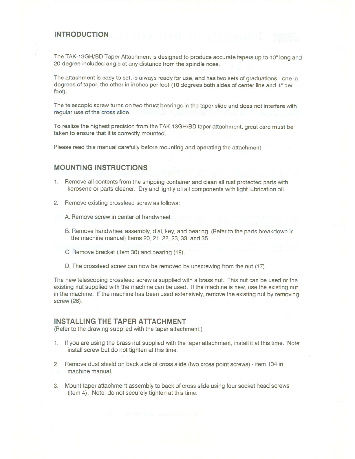
INTRODUCTION
The TAK-13GH/BDTaper Attachment is designed to produce accurate tapers up to 10"long and
20 degree included angle at any distance from the spindle nose.
The attachment is easy to set, isalways ready for use,and hastwo sets of graduations - one in
degrees of taper, the other in inches per foot (10 degrees both sides of center lineand 4" per
feet).
The telescopic screw turns on two thrust bearings inthe taper slide and does not interfere with
regular use of the cross slide.
To realizethe highest precision from the TAK-13GH/BDtaper attachment, great care must be
taken to ensure that it is correctly mounted.
Please read this manual carefully before mounting and operating the attachment.
MOUNTING INSTRUCTIONS
1. Removeall contents from the shipping container and clean all rust protected parts with
kerosene or parts cleaner. Dry and lightly oil all components with light lubrication oil.
2. Remove existing crossfeed screw as follows:
A. Remove screw in center of handwheel.
B. Remove handwheel assembly, dial, key,and bearing. (Referto the parts breakdown in
the machine manual) Items 20, 21, 22,23, 33,and 35.
C. Remove bracket (item30) and bearing (19).
D.The crossfeed screw can now be removed by unscrewing from the nut (17).
The newtelescoping crossfeed screw issupplied with a brass nut. This nut can be used or the
existing nut supplied with the machine can be used. Ifthe machine is new, usethe existing nut
in the machine. Ifthe machine hasbeen used extensively, removethe existing nut by removing
screw (26).
INSTALLING THE TAPER ATTACHMENT
(Refertothedrawingsuppliedwiththetaperattachment.)
1. Ifyou are using the brass nut supplied withthe taper attachment, install it at this time. Note:
install screw but do nottighten atthis time.
2. Remove dust shield on back side of cross slide (twocross point screws) - item 104 in
machine manual.
3. Mount taper attachment assembly to back of cross slide using four socket head screws
(item 4). Note: do not securely tighten at this time.
Page 5

4. Install new crossfeed screw and remaining components per drawing enclosed with taper
attachment. Reference section A-A.
5. Align taper attachment (using a dial indicator) so that it is parallel with the bed of the lathe.
6. Tighten all screws at this time. Check cross slide screw for free movement.
7. Thetaper attachment is supplied with no index mark on the taper slide. To adjust taper
slide to "zero":
A. Insert test bar (minimum dimensions of 3/4" diameter and 18"inlength) into the lathe
chuck.
B. Indicate test bar end to end (or length of attachment travel) and adjust taper bar until "0"
degree run-out is obtained.
C. Lock taper barto prevent movement and stake an index mark at "a"degrees. This can
be done with a small cold chisel or center punch.
8. To use the lathe to cut ataper, simply attach locking block (55)to the bed. Loosenthe
taper bar and adjust to the desired angle. The cross slide will now follow the taper bar
angle.
9. To use the lathe without the taper attachment, simply loosen and swing the locking block
(55)away from the bed.
Page 6

PARTS LIST FOR THE TAK-13GH/BD TAPER ATTACHMENT
.-J
~~
La
~.
'-27
T
u
u
l-<
Page 7

A-A SECTI ON
6
@.
.~.
0\
r/
c-c SECTION
;1\- E-E SECTION
9-9 SECTION
0 - 0 SECTION Mounlin'.! 01 b(.'"rin9 housin'.!
lwn(.'nIn!' .1IIc)chmE'nl is I"kt-n 011)
Page 8

PARTS LIST FOR THE TAK-13GH\BD TAPER ATTACHMENT
PLEASEORDER BY PART NUMBER ONLY
INDEX PART
NO. NO. DESCRIPTION
1 84-0001-00 SLlDE BASE 1
2 TS-1504081 SOCKET HEAD CAP SCREW M8x40 4
3 84-1001-00 SLlDE BRACKET 1
4 TS-1504061 SOCKET HEAD CAP SCREW M4x30 4
5 TS-1532021 COUNTER SUNK FLAT SCREW M4x8 6
6 84-0003-00 LONGITUDINAL SLIDE 1
7 84-0004-00 TAPER INDICATOR PLATE 1
8 84-0004-00-1 . RIVET 2
9 84-0005-00 ANGLE INDICATOR PLATE 1
10 84-0005-00-1 RIVET. 2
11 84-0006-00 TAPER SLIDE 1
12 TS-1503031 SOCKET HEAD CAP SCREW M6x12 1
13 TS-1503051 SOCKET HEAD CAP SCREW M6x20 1
14 84-0007-00 AXLE . , 1
15 84-0008-00 GIB STRIP 1
16 84-0006-00 ADJUSTING SCREW 2
17 84-01 OO-OO ADJUSTING PIECE 1
18 84-0011-00 ADJUSTING SCREW 1
19 84-0012-00
20 84-0012-00-1 SPRING PIN 3x14 1
21 84-0013-00 CLAMPING PIECE 1
22 84-1002-00 TAPER SLIDE REST 1
23 84-0015-00 GIB STRIP 1
24 . 84-0016-00 ADJUSTING SCREW 2
25 84-1003-00 CROSS SLIDE BLOCK 1
26 TS-1501 061 SOCKET HEAD CAP SCREW M4x20 2
27 84-1004-00 FEED BLOCK 1
29 84-1005-00 DUST COVER 1
30 84-1006-2/2-00 CROSS FEED SCREW 10 TPI 1
31 BB-511 01 THRUST BEARING 2
32 84-1007-00 PINION SHAFT 1
33 84-1007-00-1 DOUBLE ROUND HEAD KEY 5x5x30 1
34 84-1007-00-2 COUNTER SUNK FLAT SCREW M3x5 1
35 84-1007-00-3 WOODRUFF KEY 3x13 1
36 BB-51102 THRUST BEARING 1
37 17-0303A-00 CROSS BRACKET """"""""""'"'''''''''''''''''''''' 1
38 84-0023-01-1 BALL CUP " 1/4" 1
39 TS-1503051 SOCKET HEAD CAP SCREW M6x20 2
40 BB-51102 THRUST BEARING """"'''''''''''''''''''''''''''''''''''' 1
41 17-0304-00 CROSS FEED HANDWHEEL 1
42 17-0356-2/2-00 CROSS DIAL GUARD """""""'''''''''''''''''''''''''' 1
43 17-0357-00 SPRING LEAF '''''''''''''''''''''''''''''''''''''''''''''''''''' 1
44 17-0504-00-2 SOCKET BUTTON HEAD SCREW M8x20 1
: ADJUSTINGKNOB 1
SIZE
45 TS-1522061 SOCKETHEADSETSCREW M5x20 1
QTY.
Page 9

46 84-0027-00 BEARINGDUSTCOVER'"'''''''''''''''''''''''''''''''' 1
47 84-0028-00 LOCKING NUT 1
48 84-1008-00 BEARINGHOUSING , 1
49 TS-15041 01 SOCKET HEAD CAP SCREW M8x50 2
50 84-0030-00 JOI NT ,. 1
51 84-0030-00-1 SPRING PIN 4x19 .." 1
52 84-0031-00 UNIVERSAL JOINT " 1
53 84-0031-00-1 SPRING PIN .. 4x 19 1
54 84-0032-00 ADJUSTING BAR " 1
55 84-1009-00 LOCKING BLOCK ADJUSTING BAR 1
56 84-0033-00-1 SOCKET HEAD SET SCREW M8x8 1
57 TS-1504041 SOCKET HEAD CAP SCREW M8X20 1
58 84-0034-00 ECCENTRIC SHAFT 1
59 84-1010-00 ADJUSTING BAR BRACKET 1
60 TS-1524011 SOCKET HEAD SET SCREW M8x8 1
61 84-0036-00 CLAMPING BLOCK 1
62 TS-1504101 SOCKET HEAD CAP SCREW M8x50 2
63
. 17-0308-00 "'''''' BOLT 1
64 17-0307-00 HANDLE 1
65 84-0039-00 1NDICATOR 2
66 84-0039-00-1 RIVET 2x5 4
67 17-0323-2/2-00 FEED NUT 1
68 TS-1503041 SOCKET HEAD CAP SCREW M6x16 1
69 17-0305-2/2-00 DUAL DIAL.. 1
70 17-0356-00-1 ROUND HEAD SCREW M4x6 2
71 84-0002-00-3 SPRING PIN " 3x20 2
72 .. 84-0038-00 ..SPACER , 1
73 84-0021-00-2 """'''''''''''''''' LOCK WASHER AW#12 1
74 .. 17-0306-00 ..WASHER 1
Page 10

Page 11

Page 12

 Loading...