


Operating Instructions and Parts Manual
SR-2024M and SR-2236M Slip Rolls
WALTER MEIER (Manufacturing) Inc.
427 New Sanford Road
LaVergne, Tennessee 37086 Part No. M-756020
Ph.: 800-274-6848 Revision A 12/2010
www.waltermeier.com Copyright © 2010 Walter Meier (Manufacturi ng) Inc .
Warranty and Service
Walter Meier (Manufacturing) Inc., warrants every product it sells. If one of our tools needs service or repair, one of
our Authorized Service Centers located throughout the United States can give you quick service. In most cases, any
of these Walter Meier Authorized Service Centers can authorize warranty repair, assist you in obtaining parts, or
®
perform routine maintenance and major repair on your JET
your area call 1-800-274-6848.
MORE INFORMATION
Walter Meier is consistently adding new products to the line. For complete, up-to-date product information, check with
your local Walter Meier distributor, or visit waltermeier.com.
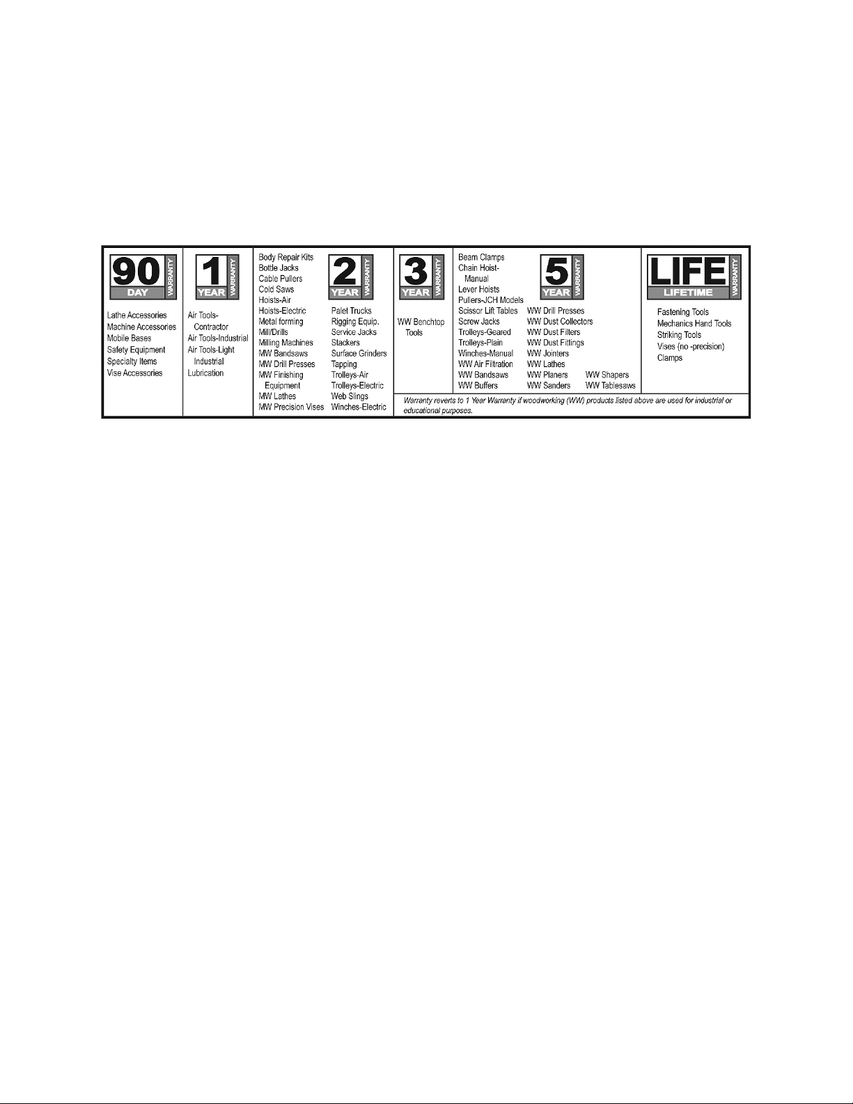
WARRANTY
JET products carry a limited warranty which varies in duration based upon the product (MW = Metalworking, WW =
Woodworking).
WHAT IS COVERED?
This warranty covers any defects in workmanship or materials subject to the exceptions stated below. Cutting tools,
abrasives and other consumables are excluded from warranty coverage.
WHO IS COVERED?
This warranty covers only the initial purchaser of the product.
WHAT IS THE PERIOD OF COVERAGE?
The general JET warranty lasts for the time period specified in the product literature of each product.
WHAT IS NOT COVERED?
Five Year Warranties do not cover woodworking (WW) products used for commercial, industrial or educational
purposes. Woodworking products with Five Year Warranties that are used for commercial, industrial or education
purposes revert to a One Year Warranty. This warranty does not cover defects due directly or indirectly to misuse,
abuse, negligence or accidents, normal wear-and-tear, improper repair or alterations, or lack of maintenance.
HOW TO GET SERVICE
The product or part must be returned for examination, postage prepaid, to a location designated by us. For the name
of the location nearest you, please call 1-800-274-6848.
You must provide proof of initial purchase date and an explanation of the complaint must accompany the
merchandise. If our inspection discloses a defect, we will repair or replace the product, or refund the purchase price,
at our option. We will return the repaired product or replacement at our expense unless it is determined by us that
there is no defect, or that the defect resulted from causes not within the scope of our warranty in which case we will,
at your direction, dispose of or return the product. In the event you choose to have the product returned, you will be
responsible for the shipping and handling costs of the return.
HOW STATE LAW APPLIES
This warranty gives you specific legal rights; you may also have other rights which vary from state to state.
LIMITATIONS ON THIS WARRANTY
WALTER MEIER (MANUFACTURING) INC., LIMITS ALL IMPLIED WARRANTIES TO THE PERIOD OF THE
LIMITED WARRANTY FOR EACH PRODUCT. EXCEPT AS STATED HEREIN, ANY IMPLIED WARRANTIES OR
MERCHANTABILITY AND FITNESS ARE EXCLUDED. SOME STATES DO NOT ALLOW LIMITATIONS ON HOW
LONG THE IMPLIED WARRANTY LASTS, SO THE ABOVE LIMITATION MAY NOT APPLY TO YOU.
WALTER MEIER SHALL IN NO EVENT BE LIABLE FOR DEATH, INJURIES TO PERSONS OR PROPERTY, OR
FOR INCIDENTAL, CONTINGENT, SPECI AL, OR CONSEQUENTIAL DAMAGES ARISING FROM THE USE OF
OUR PRODUCTS. SOME STATES DO NOT ALLOW THE EXCLUSION OR LIMITATION OF INCIDENTAL OR
CONSEQUENTIAL DAMAGES, SO THE ABOVE LIMITATION OR EXCLUSION MAY NOT APPLY TO YOU.
Walter Meier sells through distributors only. The specifications in Walter Meier catalogs are given as general
information and are not binding. Members of Walter Meier reserve the right to effect at any time, without prior notice,
those alterations to parts, fittings, and accessory equipment which they may deem necessary for any reason
®
whatsoever. JET
branded products are not sold in Canada by Walter Meier.
tools. For the name of an Authorized Service Center in
2

For your own safety, read the own er’s manual before operating the slip roll .
This slip roll i s designed and intended for use by properly trained and experienced personn el
only. If you are not familiar wit h the p roper and safe operation of a slip roll, do not use until
proper training and knowledge has been obtained.
1. KEEP GUARDS IN PLACE and in working order.
2. KEEP ALL BODY PARTS AWAY FROM MOVING PARTS. Avoid placing any part of your body
near belts, cutter s, gear s, et c .
3. DO NOT EXCEED GAUGE RATED CAPACITY on this slip roll, 20 gauge f or S R- 2024M and 22
gauge for SR-2236M.
4. KEEP THE WORK AREA CLEAN. Cluttered areas and work benches invite accidents.
5. KEEP CHILDREN AWAY. All visitors should be kept a safe distance fr om the work area.
6. MAKE THE WORKSHOP KID PROOF with padlocks, m aster switches, or by removing starter keys.
7. DON’T FORCE THE MACHINE. It will do the job bett er and saf er at t he rate for which it was
designed.
8. USE THE RIGHT MACHINE. Don’t force a machine or att ac hm ent t o do a job for whic h it was not
designed.
9. WEAR PROPER APPAREL. Do not wear loose clothing, gloves, neckti es, ri ngs, br ac elets, or other
jewelry which may get caught in moving parts. Non-slip foot wear i s recommended. Wear protective
hair covering t o contain long hair.
10. ALWAYS USE SAFETY GLASSES. Also use face or dust masks if the cutting operation is dusty.
Everyday eyeglasses only have impact resistant lenses; they are not safety gl asses.
11. DON’T OVERREACH. Keep proper f ooting and balance at all times.
12. MAINTAIN TOOLS WITH CARE. Keep tools sharp and clean for the best and saf est performance.
Follow instructions for lubricati ng and c hanging accessories.
13. NEVER STAND ON A MACHINE. Serious injury could occur if t he machine tipped.
14. CHECK DAMAGED PARTS. Before further use of the m ac hine, a guard or other part that is
damaged should be carefully checked to determine that it will operate properly and perform its
intended function - check for alignment of moving parts, binding of moving parts, br eak age of parts,
mounting, and any other c onditions that may affect it s operati on. A guard or other part that is
damaged should be properly repaired or replaced.
15. SHEET METAL STOCK HAS SHARP EDGES. To prevent cuts, use caution when handling.
16. KEEP HANDS AND FINGERS clear of the area in front and rear of the rolls.
17. DO NOT USE THE MACHINE for any purpose other than for whic h it was designed
18. FAILUR E TO C OMPLY with all of these warning s may cause serious injury .
19. SOME DUST CREATED BY power sanding, sawing, gr inding, drilling and other construction
activiti es cont ains chem icals known to cause cancer, birth defects or other reproductiv e harm. Some
examples of these chemicals are:
• Lead from lead based paint
• Crystalline sil ic a from bricks and cement and other masonry produc ts, and
• Arsenic and chromium from chemically-tr eated lumber.
20. YOUR RISK FROM THOS E EXPOSUR E S varies, depending on how often you do this type of work.
To reduce your exposure t o these chemicals: work in a well ventilated area, and work with approved
safety equipment , such as those dust masks that are specifi c ally designed to filter out mic r oscopic
particles
21. DO NOT OPERATE TOOL while under the influence of drugs, alcohol or any medication.
3

Specifications: SR-2024M SR-2236M
Stock Number................................................................. 756020 .................................................. 756026
Capacity (mil d steel) ....................................................... 20 .................................................................. 2 2
Maximum Formi ng Length .............................................. 24 ” ................................................................ 36”
Number and Diamet er of Rolls ........................................ 3 and 2” ................................................ 3 and 2”
Minimum Forming Radius ............................................... 1” .................................................................... 1”
Wire Grooves ................................................................. 3/16” 1/4", 5/16” ........................ 3/16” 1/4", 5/16”
Overall Dimensions (LxWxH) .......................................... 37” x 17” x 17” .............................. 49” x 17” x 17”
Uncrating and Clean-Up
1. Remove the crate from around the m ac hine.
2. Carefully clean all rust protected surfaces
with a mild solvent or kerosene and a soft
rag. Do not use lacquer thinner, paint
thinner, or gasoline. These will damage
painted surf ac es.
3. Coat all machi ned surfaces with a li ght coat
of oil to inhibit rust.
4. Remove the bolts holdi ng t he machine to the
skid.
5. Caref ully move t he machine t o a well li ght ed
area on a solid, level work bench, and
secure to the bench with lag screws or bolts.
6. Machine location must allow access to all
sides.
Front Rolls
The (#) in the text ref er s to the break down.
1. The upper and lower rolls #23 & #24 carry
the material through as the crank handle
#33 is turned in a clockwise di r ec tion.
2. The lower roll adjustment knobs #12 are
used to move the lower roll #24 up and
down for different gauge material.
3. The gap bet ween the two f ront rolls should
be equal at both ends.
Rear Roll
1. The rear rol l #25 can be adj usted to control
the radius by turning adjustment knobs #13.
2. The gap between the rear roll and the two
front rolls should be equal at both ends of
the roll to assure an equal radius at both
ends of the material.
Releasing the Material
1. Once the material has been rolled release
the material from the roll by lifting handle
#29. Move the handle bracket out of the
way.
2. Lift the upper rol l #23 by m oving l ever #3 t o
the right so that the material can be
removed.
Rolling Wir es
There are three wire grooves in the lower and
rear rolls that will accommodate a 3/16”, 1/4",
and 5/16” wire.
Lubrication
The machine must be lubricated every day of
service wit h a few drops of oil. An oil pi nhole is
located at both ends of the lower roll #24, and
rear roll #25. The upper roll #23 has two oil
pinholes on the left side. The right side c an be
lubed by opening the handle #29, and lightly
oiling the end of the upper roll shaft.
Every thirty day s of operation gr ease the gears
by removing the outer hex nut #7, and gear
cover #18.
Lightly oil the rolls when not in use to prevent
rust.
4

Breakdown for the SR-2024M & SR-2236M Slip Roll
5

Parts List for the SR-2024M & SR-2236M Slip Roll
Index Part
No. No. Description Size Quantity
1 .......... SR2024N-1 ...................Base Assem bly ...................................... ............................................... 1
............ SR2236N-1 ...................Base Assembly ...................................... ............................................... 1
3 .......... SR2024N-3 ...................Lever ..................................................... ............................................... 1
4 .......... SR2024N-4 ...................Rod ....................................................... ............................................... 1
............ SR2236N-4 ...................Rod ....................................................... ............................................... 1
5 .......... SR2024N-5 ...................Socket Head Cap Screw ........................ M8x20 ..................................... 3
6 .......... SR2024N-6 ...................Socket Head Cap Screw ........................ M10x25 ................................... 1
7 .......... SR2024N-7 ...................Hex Nut ................................................. M10 ........................................ 3
8 .......... SR2024N-8 ...................Hex Cap Screw ..................................... M12x20 ................................... 4
9 .......... SR2024N-9 ...................Left Support ........................................... ............................................... 1
10 ........ SR2024N-10 .................Upper Left Bearing Seat ........................ ............................................... 1
11 ........ SR2024N-11 .................Lower Left Bearing Seat ........................ ............................................... 2
12 ........ SR2024N-12 .................Knob ..................................................... ............................................... 2
13 ........ SR2024N-13 .................Knob ..................................................... ............................................... 2
14 ........ SR2024N-14 .................Gear ...................................................... ............................................... 1
15 ........ SR2024N-15 .................Set Screw Flat Point .............................. M8x8....................................... 4
16 ........ SR2024N-16 .................Gear ...................................................... ............................................... 1
17 ........ SR2024N-17 .................Spring Pi n.............................................. 5x20........................................ 3
18 ........ SR2024N-18 .................Gear Cov er ............................................ ............................................... 1
19 ........ SR2024N-19 .................Right Support ........................................ ............................................... 1
20 ........ SR2024N-20
22 ........ SR2024N-22 .................Bearing Seat ......................................... ............................................... 2
23 ........ SR2024N-23 .................Upper Roll ............................................. ............................................... 1
............ SR2236N-23 .................Upper Roll ............................................. ............................................... 1
24 ........ SR2024N-24 .................Lower Roll ............................................. ............................................... 1
............ SR2236N-24 .................Lower Roll ............................................. ............................................... 1
25 ........ SR2024N-25 .................Rear Roll ............................................... ............................................... 1
............ SR2236N-25 .................Rear Roll ............................................... ............................................... 1
26 ........ SR2024N-26 .................Link Rod ................................................ ............................................... 1
............ SR2236N-26 .................Link Rod ................................................ ............................................... 1
27 ........ SR2024N-27 .................Spring Pi n.............................................. 8x45........................................ 1
28 ........ SR2024N-28 .................Cover .................................................... ............................................... 1
29 ........ SR2024N-29 .................Handle................................................... ............................................... 1
30 ........ SR2024N-30 .................Cam ...................................................... ............................................... 1
31 ........ SR2024N-31 .................Handle Bracket ...................................... ............................................... 1
32 ........ SR2024N-32 .................Handle................................................... ............................................... 1
33 ........ SR2024N-33 .................Arm ....................................................... ............................................... 1
34 ........ SR2024N-34 .................Pin......................................................... ............................................... 1
35 ........ SR2024N-35 .................Flat Head Screw .................................... M4x5....................................... 4
36 ........ SR2024N-36 .................Plate ...................................................... ............................................... 2
37 ........ SR2024N-37 .................Set Screw Cone Point............................ M8x8....................................... 2
............ SR2024M-ID .................ID Label (not shown).............................. ............................................... 1
............ SR2236M-ID .................ID Label (not shown).............................. ............................................... 1
............ SR2024N-W..................Warning Label (not shown) .................... ............................................... 1
............ SR2024N-J ...................JET Label (not shown) ........................... ............................................... 1
.................Spring Pi n.............................................. 8x20........................................ 1
6

7

WALTER M EIE R (Manufa c turing) Inc.
427 New Sanford Road
LaVergne, Tennessee 37086
Phone: 800-274-6848
www.jettools.com
www.waltermeier.com
8
 Loading...