

Page 1

Operating Instructions and Parts Manual
Shear, Brake and Roll Machines
Models SBR-30M, SBR-40M
WALTER M EIE R (Manufa c turing) Inc.
427 New Sanford Road
LaVergne, Tennessee 37086 Part No. M-756031
Ph.: 800-274-6848 Revision A 08/2011
www.waltermeier.com Copyright © 2011 Walter Meier (Manufacturi ng) Inc .
Page 2

1.0 Warranty and Service
Walter Meier (Manufacturing) Inc., warrants every product it sells. If one of our tools needs service or repair, one of
our Authorized Service Centers located throughout the United States can give you quick service. In most cases, any
of these Walter Meier Authorized Service Centers can authorize warranty repair, assist you in obtaining parts, or
®
perform routine maintenance and major repair on your JET
your area call 1-800-274-6848.
MORE INFORMATION
Walter Meier is consistently adding new products to the line. For complete, up-to-date product information, check with
your local Walter Meier distributor, or visit waltermeier.com.
WARRANTY
JET products carry a limited warranty which varies in duration based upon the product (MW = Metalworking, WW =
Woodworking).
WHAT IS COVERED?
This warranty covers any defects in workmanship or materials subject to the exceptions stated below. Cutting tools,
abrasives and other consumables are excluded from warranty coverage.
WHO IS COVERED?
This warranty covers only the initial purchaser of the product.
WHAT IS THE PERIOD OF COVERAGE?
The general JET warranty lasts for the time period specified in the product literature of each product.
WHAT IS NOT COVERED?
Five Year Warranties do not cover woodworking (WW) products used for commercial, industrial or educational
purposes. Woodworking products with Five Year Warranties that are used for commercial, industrial or education
purposes revert to a One Year Warranty. This warranty does not cover defects due directly or indirectly to misuse,
abuse, negligence or accidents, normal wear-and-tear, improper repair or alterations, or lack of maintenance.
HOW TO GET SERVICE
The product or part must be returned for examination, postage prepaid, to a location designated by us. For the name
of the location nearest you, please call 1-800-274-6848.
You must provide proof of initial purchase date and an explanation of the complaint must accompany the
merchandise. If our inspection discloses a defect, we will repair or replace the product, or refund the purchase price,
at our option. We will return the repaired product or replacement at our expense unless it is determined by us that
there is no defect, or that the defect resulted from causes not within the scope of our warranty in which case we will,
at your direction, dispose of or return the product. In the event you choose to have the product returned, you will be
responsible for the shipping and handling costs of the return.
HOW STATE LAW APPLIES
This warranty gives you specific legal rights; you may also have other rights which vary from state to state.
LIMITATIONS ON THIS WARRANTY
WALTER MEIER (MANUFACTURING) INC., LIMITS ALL IMPLIED WARRANTIES TO THE PERIOD OF THE
LIMITED WARRANTY FOR EACH PRODUCT. EXCEPT AS STATED HEREIN, ANY IMPLIED WARRANTIES OR
MERCHANTABILITY AND FITNESS ARE EXCLUDED. SOME STATES DO NOT ALLOW LIMITATIONS ON HOW
LONG THE IMPLIED WARRANTY LASTS, SO THE ABOVE LIMITATION MAY NOT APPLY TO YOU.
WALTER MEIER SHALL IN NO EVENT BE LIABLE FOR DEATH, INJURIES TO PERSONS OR PROPERTY, OR
FOR INCIDENTAL, CONTINGENT, SPECI AL, OR CONSEQUENTIAL DAMAGES ARISING FROM THE USE OF
OUR PRODUCTS. SOME STATES DO NOT ALLOW THE EXCLUSION OR LIMITATION OF INCIDENTAL OR
CONSEQUENTIAL DAMAGES, SO THE ABOVE LIMITATION OR EXCLUSION MAY NOT APPLY TO YOU.
Walter Meier sells through distributors only. The specifications in Walter Meier catalogs are given as general
information and are not binding. Members of Walter Meier reserve the right to effect at any time, without prior notice,
those alterations to parts, fittings, and accessory equipment which they may deem necessary for any reason
®
whatsoever. JET
branded products are not sold in Canada by Walter Meier.
tools. For the name of an Authorized Service Center in
2
Page 3

2.0 Table of Contents
Section Page
1.0 Warranty and Service ....................................................................................................................... 2
2.0 Table of Contents ............................................................................................................................. 3
3.0 Safety Warnings ............................................................................................................................... 4
4.0 About this manual ............................................................................................................................. 5
5.0 Specifications ................................................................................................................................... 6
6.0 Set-Up and Assembly ....................................................................................................................... 7
6.1 Floor Diagrams.............................................................................................................................. 7
6.2 Unpacking ..................................................................................................................................... 8
6.3 Assembly ...................................................................................................................................... 8
6.4 Press Brake set-up ........................................................................................................................ 9
6.5 Shear set-up ................................................................................................................................. 9
6.6 Slip Roll set-up ............................................................................................................................ 1 1
7.0
Maintenance/Lubrication
8.0 Optional Accessories ...................................................................................................................... 13
9.0 Troubleshooting .............................................................................................................................. 14
10.0 Replacement Parts ....................................................................................................................... 14
10.1.1 SBR-30M Shear/Brake/Roll – Exploded Vi ew ......................................................................... 15
10.1.2 SBR-30M Shear/Brake/Roll – Parts List .................................................................................. 16
10.2.1 SBR-40M Shear/Brake/Roll – Exploded Vi ew ......................................................................... 18
10.2.2 SBR-40M Shear/Brake/Roll – Parts List .................................................................................. 19
................................................................................................................... 13
3
Page 4

3.0 Safety Warnings
1. Read and understand enti re owner’s m anual
before attempting assembly or operation.
2. Read and understand the warnings posted
on the machi ne and in this manual. F ai lure
to comply with all of these warnings may
cause serious injury.
3. Replace warning labels if they become
obscured or removed.
4. This shear/brake/roll machine is designed
and intended for use by proper ly t rained and
experienced personnel only. If you are not
familiar with the proper and safe operation of
a shear/brake/roll, do not use until proper
training and knowledge have been obtained.
5. Do not use this machine for other than its
intended use. If used for other purposes,
Walter Meier ( M anufacturing), Inc., disclaims
any real or im plied warranty and holds it self
harmless from any injury that may result
from that use.
6. This shear, brake and roll is int ended to be
used by one person only. K eep others away
from the machine during operations.
14. Keep hands and fingers away from the
press brake dies.
15. Do not exceed t he maximum capacit y of the
machine.
16. Do not use the shear to cut round bars,
chain, steel cable or hardened metals.
17. Before operating this machine, remove tie,
rings, watches and other jewelry, and roll
sleeves up past the elbows. Remove all
loose clothing and confine long hair.
18. Some dust created by power sanding,
sawing, grinding, drilling and other
construction activities contains chemicals
known to cause cancer, birth defects or
other reproductiv e harm . Some ex amples of
these chemicals are:
• Lead from lead based paint.
• Crystalline silica from bricks, cement
and other masonry product s.
• Arsenic and chromium from chemically
treated lum ber.
Your risk of exposure vari es, depending on
how often you do this type of work. To
reduce your exposure to these chemicals,
work in a well-ventil ated area and work with
approved safet y equipm ent, such as f ace or
dust masks that are specificall y designed to
filter out microscopic particles.
7. The shear, brake and roll must be bolted
securely to a stand and the stand bolted
securely to the f loor. If the mac hine is to be
bench-mount ed, the bench must be able to
support the weight of the machi ne and must
be bolted to the floor.
8. Always wear approved safety glasses/face
shields while using this machine. Everyday
eyeglasses only have impact resistant
lenses; they are not s af ety glasses.
9. Keep the floor around the shear, brake and
roll clear of scraps, debris, oil and grease.
The flooring ar ound the machine should be
a non-skid type.
10. Sheet metal stock has sharp edges. To
prevent cuts, deburr edges and use gloves
when handling.
11. K eep top guard in place when not using the
slip roll.
12. K eep hands and finger s clear of the slip roll
pinch point s.
13. Keep hands and f ingers away f rom the area
in front and rear of the shear blades.
19. Do not operate this machine while tired or
under the infl uence of drugs, al cohol or any
medication.
20. Check dam aged parts. Bef ore furt her use of
the machine, a guard or other part that is
damaged should be carefully checked to
determine that it will operate properly and
perform its intended function. Check for
alignment or binding of moving parts,
breakage of parts, mounting and any other
conditions that may affect its operation. A
guard or other part t hat is damaged should
be properly repaired or replaced.
21. Provide for adequate space surrounding
work area and non-glare, overhead lighting.
22. G ive your work undivi ded attention. Look ing
around, carrying on a conversation and
“horse-play” are c ar eless acts that can result
in serious injury.
4
Page 5

Familiarize you rself with the following safety no ti ces used in this manual.
This means that if precautions are not heeded, it may result i n mi nor i njur y and/or
possible machine damage.
This means that if precautions are not heeded, it may result i n serious or even fatal
injury.
4.0 About this manual
This manual is provided by Walter Meier (Manufacturing) Inc. covering the safe operation and
maintenance pr ocedures for a JET model SBR-30M and S BR-40M Shear, Brak e and Roll. T his manual
contains instructions on installation, safety precautions, general operating procedures, maintenance
instructi ons and parts breakdown. Your machi ne has been designed and con structed to pr ovide year s of
trouble-f r ee oper ation if used in accordance with the i nstructions as set forth in thi s docum ent.
If there are questions or c omments, please contact your local suppli er or Walter Meier. Walt er Meier can
also be reached at our web site: www.walt er meier.com.
Retain this manual for future reference. If the machine transfers ownership, the manual should
accompany it.
Read and understand the entire contents of this manual before attempting set- up
or operation. Failu re to comply may cause serious injury.
5
Page 6

5.0 Specifications
Model Number ............................................................................ SBR-30M ............................................ SBR-40M
Stock Number ................................................................................ 756031 ................................................ 756041
Materials:
Frame ....................................................................................... cast iron .............................................. cast iron
Table ......................................................................................... cast iron .............................................. cast iron
Handles ........................................................................................... steel .................................................... steel
Rolls ................................................................................................ steel .................................................... steel
Capacities & Dimensions:
Capacity - mild steel ..................................................................... 20 ga. .................................................. 20 ga.
Footprint (LxW) ....................................... 32-1/2”x14-1/2” (826x368mm) ....................... 43”x18” (1096x457mm)
Dimensions, assembled (LxWxH) .......44”x14”x24” (1118x356x610mm) ... 54”x18”x27-1/2”(1372x457x699mm)
Shearing:
Shearing capacity ................................................ 20 ga. x 30” (762mm) ........................ 20 ga. x 40” (1016mm)
Shear blade ............................................................................ reversible ............................................ reve rsible
Bending:
Bending capacity ................................................. 20 ga. x 30” (762mm) ........................ 20 ga. x 40” (1016mm)
No. of male dies .................................................................................... 7 .......................................................... 8
No. of female dies ................................................................................. 1 .......................................................... 1
Width of upper dies ....................................................1, 2, 3, 4, 4, 6, 10” ........................... 1, 2, 2, 4, 6, 7, 8, 12”
Upper die height ............................................................ 4-3/4” (121mm) ................................... 4-3/4” (121mm)
Rolling:
Rolling capacity .................................................... 20 ga. x 30” (762mm) ........................ 20 ga. x 40” (1016mm)
Wire grooves (dia.) ........................................................ 1/8”, 3/16”, 1/4" ................................... 1/8”, 3/16”, 1/4"
Size of slip rolls (dia. x L) ................................ 1-1/2” x 30” (38x762m m ) .................. 1-5/8” x 40” (41x1016mm)
Minimum forming radius ..................................................... 3/4” (19mm) ........................................ 1” (25.4mm)
Weights:
Net ................................................................................. 286 lb. (130 kg) ................................... 506 lb. (230 kg)
Shipping ......................................................................... 332 lb. (151 kg) ................................... 561 lb. (255 kg)
The specifications in this manual were current at time of publication, but because of our policy of continuous
improvement, Walter Meier (Manufacturing) Inc., reserves the right to change specifications at any time and
without prior notice, without incurring obligations.
6
Page 7
6.0 Set-Up and Assembly
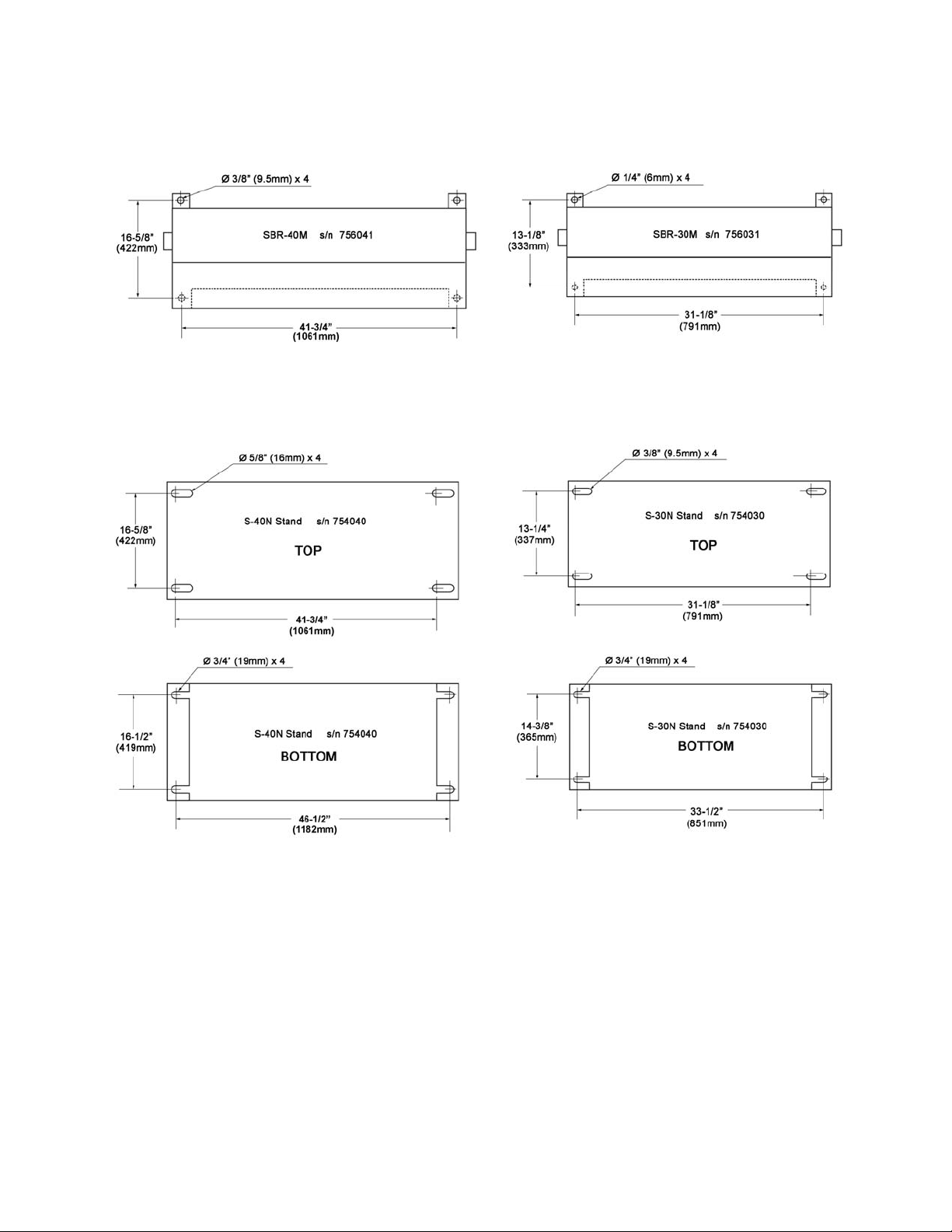
6.1 Floor Diagrams
Figure 1 – hole centers for S hear , Br ak e and Roll
Figure 2 – hole centers for Stands (OP TIONAL)
7
Page 8

6.2 Unpacking
Open shipping cont ainer and check f or shipping
damage. Report any damage immediately to
your distributor and shipping agent. Do not
discard any shipping material until the
Shear/Brake/Roll machine is assembled and
running properl y .
Compare the c ontents of y our cont ainer wit h the
following parts list to make sure all parts are
intact. Missing par ts, if any, should be reported
to your distributor. Read the instruction manual
thoroughly for assembly, maintenance and
safety instructions.
Contents of Shipping Container
1 Shear, Brake and Roll m ac hine
2 Handle assemblies
2 Guide rods with hex nuts
1 Guide plate
2 Mounting Bloc k s with T-handles
1 Instructi ons and Par t s Manual
1 Warranty Card
6.3 Assembly
Tools required for s et up and assem bly :
Figure 3
8. Loosen lock bolt (C, Figure 3).
9. Slide bar (B) into hub and tighten lock bolt
(C) to secure.
10. Re- install handle (A).
11. Install bot h guide rods into either the upper
or lower set of threaded hol es (Figures 4/5)
and tighten the setting by rotating hex nut
against the cast base of the machine with
19mm wrench.
5, 6, 8mm hex keys (“Allen wrenches”)
19mm open end wrench
1. Finish removing crate from around machine.
2. Remove bolts holding machine to pallet.
3. Carefully clean all rust protected surfaces
with a mild solvent or kerosene and a soft
rag. Do not use lacquer thinner, paint
thinner, or gasoline, as these may damage
painted surfaces.
4. Coat all machined surfac es with a very light
film of oil to i nhibit rust.
5. Caref ully move machine to a work bench or
stand. Machine location must allow free
access on all sides.
6. Bolt machine to stand or workbench. The
stand or workbench must be bolted to the
floor.
(NOTE: An optional stand is available for
this machine; see Section 9. Contact your
JET distri but or t o order. )
Figure 4
(Brake position)
7. Remove one handle ( A, Fi gure 3) f rom eac h
operating handl e assembly, using 8mm hex
key.
Figure 5
(Shear position)
8
Page 9

NOTE: For brake operation, install guide
rods into upper set of holes (Figure 4); for
shear operation, install in lower set of hol es
(Figure 5).
12. Install guide plate as shown in Fi gures 4 or
5. Secure it to rods using the T- handles.
10. Hold workpiece steady and use operating
handle to make bend.
To adjust brake beam (G, Figure 7) for 90°
bends at bot tom of stroke:
1. Slightly loosen locking screws (H) using
8mm hex key.
6.4 Press Brake set-up
Do not bend material larger
than 30” (40” ) 20-gauge mi ld steel. Fai lure to
comply may cause serious injury and/or
damage to the machine.
To set up for bending:
1. Place a strip of wood (D, Figure 6) on
bottom die, the full length of die.
2. Close brake until the wood contacts upper
dies (E).
3. Loosen screws (F ) usi ng 6mm hex key.
2. Turn brake beam adjusting screws (J) with
19mm wrench, until test bends reflect 90°
bend at both ends of brake.
3. Re-tighten screws (H).
Figure 7
For special repetitive bends, the brake beam
may be adjust ed to over-bend t he desired angle
since the metal will hav e some degree of “spring
back”.
Figure 6
4. Select upper dies (E) for desired job and
remove the others by sliding them out the
left end.
5. Move operating handle until the wood
pushes up the dies so that they seat
uniformly in upper beam.
6. Securely re-tighten all screws (Figure 4),
then release and remove wood strip.
7. If making repeated bends or using a long
workpiece, posit ion guide rods and pl ate for
brake operation, as shown in Figure 4.
8. Scribe a line on workpiece for bend l ocation.
(Be sure to accommodate bend allowance
based upon thi ckness of material. This can
be done either through trial and error, or by
consulting a m ac hinist’s handb ook .)
9. Rest workpiece on v-block (lower die) so
that the scri bed line is aligned with the t ips
of upper die(s).
6.5 Shear set-up
than 30” (40” ) 20 gauge mild steel. Failu re to
comply may cause serious injury and/or
damage to the machine.
1. Install gui de rods and plat e i n shear posit i on
(Figure 5) and adjust to desired length of
workpiece cut.
2. Pl ace workpiece agai nst guide bl ock at right
edge of table (K, Figure 8). The end of
workpiece should be against guide plate.
3. Operate handle to begin shearing cut.
Shearing action pr ogr esses from right to left.
NOTE: To prevent distortion when notching,
“snap” the handle to f acili tate piercing.
Do not shear material larg er
9
Page 10

Figure 8
Figure 10
6.5.2 Blade Rotation/Replacement
6.5.1 Lower Blade Adjustment
Upper and lower shear blades have been factor y
aligned and should not require immediate
adjustment. Should re-alignment be needed in
the future, proceed as follows:
1. Place a heav y sheet of paper in t he cutting
position, along entire length of bed, and
make a cut.
2. If the shear does not cut t he paper, loosen
screw (L, Fi gur e 8) at each end of table, wit h
8mm hex key.
3. Rotate adjustment screws (M, Figure 9) to
shift table and change the gap between
blades. Do not allow the blades to
overlap.
Exercise caution when
working with or near the blades. Use work
gloves when handling them.
The shearing blades are reversible and
interchangeable; when the edges dull, rotate
them to the new edge, as follows:
1. Remove hold-down by loosening screws (O,
Figure 11), using 6mm hex k ey.
2. Raise upper blade to hi ghest posi tion.
3. Remove seven screws (P, Figure 11) and
carefully r emove blade.
4. Rotate or r eplace blade and re-install screws
(P).
5. Reinstall hold-down. When blade is in
highest positi on, the gap between the holddown and the table should be within 1/4”.
Adjust to this position by turning the two
screws (O, Fi gure 11) as needed. W hen the
blade starts its downward travel, the holddown should imm ediately hold workpiec e in
place.
Figure 9
4. If t he shear cuts the paper on the ends, but
not the center, slight ly turn scre w (N, Figur e
10) clockwise until paper is cut the entire
length.
5. If the shear cuts the paper in t he center, but
not the ends, turn screw (N)
counterclockwise until paper i s cut the enti re
length.
Figure 11
10
Page 11

6.6 Slip Roll set-up
π
C
π
D
Do not roll material larger
than 30” (40”), 20-gauge
mild steel. The slip roll guard must cover the
rolls except when material is being fed into
the rolls. Failure to comply may cause
serious injury and/or damage to the machine.
Material Size Considerations
To determine approximate length of material
needed for a de si r ed size tube, use the foll owing
formula:
where
equals 3.1417
and
For example: To find the length of material
needed (C) to form a tube 4" in diameter,
multiply 3.1417 by 4". Result: 12.5667" is the
circumferenc e of approximate length of material
needed. Cut several pieces of material to this
length for a forming test r un. Mat eri al may hav e
to be lengthened or shortened depending upon
results of te st run .
TIP: If it doesn’t int erf ere wit h the pr oposed f i nal
shape or design, a slight bend made with the
press brake on the l eading ed ge will simplify the
initial rolling process, by allowing the leading
edge to slip more easily over the idle roll.
intersection of upper and lower rol ls. Failure
to comply may cause serious injury to
fingers and/or hands.
1. Make sure rolls and workpiece are clean
and free of debr is to prev ent pitti ng of sheet
metal.
,
DC
=
is the circumferenc e,
is the diameter.
Beware of pin ch point – the
3. Loosen bolt (R, Figure 12) to increase space
between upper and lower press rol ls.
4. Insert material between upper and lower
rolls, and t ight en bol t (R, Figur e 12) to l ower
the upper roll, until material fits snugly. The
upper roll must have sufficient pressure on
work piece to feed pr operl y .
5. Rotate both idle roll screws (Q, Figure 12) to
adjust idle roll’s proximity to the two main
rollers. Raise both ends an equal amount.
6. Run workpiece through the machine using
the handles. If workpiece is large, make
sure it receives proper support as it exi ts the
machine.
7. Make further passes of workpiece, raising
the idle roll increm entally before each pass,
until desired radius is achieved.
No exact f ormula can be fol lowed when mak ing
roll adjustments because material “spring-back”
varies with the kind of material being formed.
Only by t est forming several pieces can correct
adjustment s be obtained. Also, keep in mind t hat
it is much easier to re-pass material to m ake a
smaller radius than to attempt to increase a
radius that was made too small.
The idle r oll must be adjusted ex actly par allel or
the materi al wi ll spi ral duri ng the roll i ng process.
Measure each end of the opening with calipers if
greater preci si on is required.
Deliberat ely setting the roll s non-parallel can be
used to make cone shapes.
To remove cylind rical shap ed workpieces:
1. Loosen bolt (R, Figure 13)
2. Loosen thumb screw (S) to release the roll
catch.
2. Back off idle roll completely by rotating idle
roll screws (Q, Figure 12) counter - cl oc k wise.
Figure 13
3. Caref ully grasp upper roll and swing out the
end.
Figure 12
11
Page 12

Grasp upper roll firmly, to
prevent it fallin g out of machine.
4. Slip workpi ec e off end of r oll.
5. Reinstall upper roll, and tighten screw and
bolt (S, Figure 13).
6.6.1 Flat Roll ing
Softer metals (copper, aluminum, etc.) can be
processed through the slip roll machine to
straighten, flatten, or reduce their thickness.
Simply adj ust the upper press roll for thickness,
lower idle roll all the way down, and feed
workpiece through (Figure 14).
Figure 14
NOTE: The i dle roll will not descend com pletely
out of t he path of the wor k piece; thus, t her e may
be a slight bend in the workpiece. By flipping t he
workpiece over and re-feedi ng it , this bend can
be minimized.
2. Feed workpiece into machine. As it nears
the end (a, Figure 16), stop and reverse
direction (b, Fi gure 16).
3. Make further passes if needed, along with
increment al idle roll adjustments.
Figure 16
6.6.4 Bending Wire
There are three wire groov es at the end of t he
press roller s to ac c ommodate a 1/8”, 3/16” and a
1/4” wire.
Use the small est groove into whi ch the wire wil l
comfortably fit. Bend the wire using the same
principles as de scribed for f orming a radius. To
make a complete loop of wire, use the
instructions for forming a tube.
6.6.2 Forming a Radius
1. Adjust upper pr ess rol l as needed.
2. Insert workpiece from front.
3. Operate handle; when the mat erial reac hes
the point where the radius is to begin (a,
Figure 15), stop the machine and raise the
idle roll an equal amount on each end to
achieve desired bend.
Figure 15
4. Restart rolls and continue until bend is
completed ( b, Figure 15). Support workpiece
as it exits machine.
5. Make further passes if needed, along with
increment al idle roll adjustments.
6.6.3 Forming a Tube
1. Adjust upper press roll as needed for
workpiece thickness.
12
Page 13

7.0
Maintenance/Lubrication
8.0 Optional Accessories
Use caution when doing
maintenance work around
the shear blades.
1. Apply #2 lithium tube grease once a m onth
to the grease ni pples on both end s of frame
(A, Figure 17).
2. Keep the slip rolls clean and rust-free, and
frequently apply a light coat of oil to them.
3. Lightly brush m ulti-purpose grease ont o the
gears at the end of the roller s (B, Figure 17).
Turn operating handle to distribute the
grease.
4. Keep other exposed area s clean and lightly
coated with oil, such as the shear blades,
table and upper dies. (Remove upper dies
from bar for more eff ective cleaning).
Part No. Description
754030 Optional Stand f or SBR - 30N/ M
754040 Optional Stand f or SBR - 40N/ M
Figure 18 - Optional St and
Figure 17
13
Page 14

9.0 Troubles hooting
Trouble Probable Cause Remedy
SHEAR
Material won’t cut.
Incorrect blade gap.
Machine capacity exceeded. Use materials within capacity.
Unequal blade gap. Make blade gap equal.
Adjust gap to accommodate thicke r
materi al.
Cuts not square.
Poor cut quality.
BRAKE
Workpiece not bending,
or bending difficult.
Bend radius not
consistent across
materi al.
SLIP ROLL
Cones are made when
trying to roll cyli nders.
Workpiece not bending.
Not contacting table guides. Maintain consistent guides contact.
Blade is bowed. Remove bow.
Insufficient hold-down pressure. Adjust hold down.
Dull blade(s). Replace or sharpen.
Incorrect blade gap. Adjust gap as needed.
Loose gibs. Adjust backlash out of gibs.
Workpiece too thick. Use materials within capacity.
Improper bend allowance. Adjust brake beam for proper bend size.
Machine capacity exceeded. Use materials within capacity.
Brake beam improperly set for bending
allowance.
Rolls no t para l lel .
Machine capacity exceeded. Use materials within capacity.
Idle roll not engaging. Inspect and make corrections as needed.
Adjust brake beam for consistent bend.
Adjust idle (rear) roll until parallel to upper
press roll.
10.0 Replacement Parts
Replacement par ts are li sted on the f ollowing page s. To order par ts or reach our serv i ce departm ent, call
1-800-274-6848, Monday through Friday (see our website for business hours, www.waltermeier.com).
Having the Model Number and Serial Number of your mac hine available when you call will allow us to
serve you quickly and accurately.
NOTE: Non-proprietary fasteners (part num bers beginning with T S-) are standard sizes, and can usuall y
be found at local tool stores.
14
Page 15
10.1.1 SBR-30M Shear/Brake/Roll – Exploded View
15
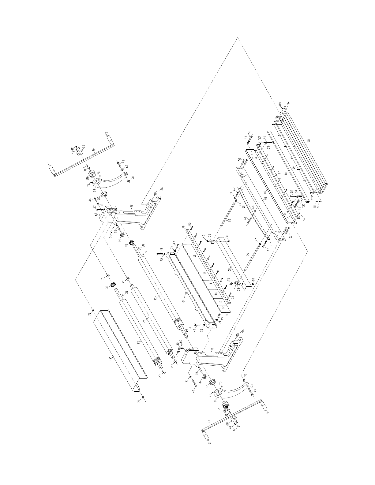
Page 16

10.1.2 SBR-30M Shear/Brake/Roll – Parts List
Index No. Part No. Description Size Qty
01 ............. SBR30M-01 .............Frame (left) .................................................. ......................................... 1
02 ............. SBR30M-02 .............Frame (right) ............................................... ......................................... 1
03 ............. SBR30M-03 .............Arm ............................................................. ......................................... 2
04 ............. SBR30M-04 .............Cross Beam ................................................ ......................................... 1
05 ............. SBR30M-05 .............Table ........................................................... ......................................... 1
06 ............. SBR30M-06 .............Spacer Bar .................................................. ......................................... 1
07 ............. SBR30M-07 .............Cutter Plate ................................................. ......................................... 1
08 ............. SBR30M-08 .............Guide Plate ................................................. ......................................... 1
09 ............. SBR30M-09 .............Guide Rod ................................................... ......................................... 2
10 ............. SBR30M-10 .............Guide Bar .................................................... ......................................... 1
11 ............. SBR30M-11 .............Brake Forming Die ....................................... 1” ...................................... 1
12 ............. SBR30M-12 .............Brake Forming Die ....................................... 2” ...................................... 1
13 ............. SBR30M-13 .............Brake Forming Die ....................................... 3” ...................................... 1
14 ............. SBR30M-14 .............Brake Forming Die ....................................... 4” ...................................... 2
15 ............. SBR30M-15 .............Brake Forming Die ....................................... 6” ...................................... 1
16 ............. SBR30M-16 .............Brake Forming Die ....................................... 10” .................................... 1
17 ............. S BR30M-17 .............C utter .......................................................... ......................................... 1
18 ............. SBR30M-18 .............Press Plate .................................................. ......................................... 1
19 ............. S BR30M-19 .............C utter .......................................................... ......................................... 1
20 ............. SBR30M-20 .............Handle Bar .................................................. ......................................... 2
21 ............. SBR30M-21 .............Handle......................................................... ......................................... 4
22 ............. S BR30M -22 .............Co ver .......................................................... ......................................... 1
23 ............. SBR30M-23 .............Roll.............................................................. ......................................... 1
24 ............. SBR30M-24 .............Lower Press Roll ......................................... ......................................... 1
25 ............. SBR30M-25 .............Upper Press Roll ......................................... ......................................... 1
26 ............. SBR30M-2 6 .............Eccentric Shaft ............................................ ......................................... 2
27 ............. SBR30M-27 .............Bushing ....................................................... ......................................... 2
28 ............. SBR30M-2 8 .............Eccentric Cap .............................................. ......................................... 2
29 ............. SBR30M-29 .............Bushing ....................................................... ......................................... 4
30 ............. SBR30M-30 .............Gear ............................................................ ......................................... 2
31 ............. S BR30M -31 .............Pivot Bushing .............................................. ......................................... 2
32 ............. SBR30M-32 .............Thumb Screw .............................................. ......................................... 1
33 ............. SBR30M-33 .............Guide Block ................................................. ......................................... 2
34 ............. SBR30M-34 .............Block ........................................................... .................... ..................... 1
35 ............. SBR30M-3 5 .............Screw .......................................................... ......................................... 2
36 ............. SBR30M-36 .............Locating Bolt ............................................... ......................................... 2
37 ............. SBR30M-37 .............Adjustable Bolt ............................................ ......................................... 2
38 ............. SBR30M-38 .............Key.............................................................. 8x7x25mm ........................ 2
39 ............. SBR30M-39 .............Key.............................................................. 5x5x6mm .......................... 2
40 ............. TS-1503031 .............Socket Head Cap Screw .............................. M6x12 .............................. 4
41 ............. TS-1503031 .............Socket H
42 ............. SBR30M-42 .............T-Handle ..................................................... M8x25 .............................. 2
43 ............. S BR30M-43 .............H ex Cap Bolt ............................................... M12x70 ............................ 2
44 ............. SBR30M-44 .............Star Grip Knob............................................. M10 .................................. 2
45 ............. SBR30M-42 .............T-Handle ..................................................... M8x25 .............................. 2
46 ............. TS-1482081 .............Hex Cap Screw ........................................... M6x40 .............................. 2
47 ............. TS-1505021 .............Socket Head Cap Screw .............................. M10x20 ............................ 2
48 ............. TS-2211451 .............Hex Cap Screw ........................................... M12x45 ............................ 2
49 ............. TS-1505051 .............Socket Head Cap Screw .............................. M10x35 ............................ 2
50 ............. TS-1504051 .............Socket Head Cap Screw .............................. M8x25 ............................ 1 0
51 ............. TS-1505041 .............Socket Head Cap Screw .............................. M10x30 ............................ 4
52 ............. SBR30M-5 2 .............Screw .......................................................... ......................................... 2
53 ............. S BR30M-53 .............H ex Cap Bolt ............................................... M8x90 .............................. 2
54 ............. SBR30M-54 .............Pressure Plate Bracket ................................ ......................................... 2
55 ............. SBR30M-55 .............Spring.......................................................... ......................................... 2
56 ............. TS-1505031 .............Socket Head Cap Screw .............................. M10x25 ............................ 2
ead Cap Screw .............................. M6x12 .............................. 2
16
Page 17

Index No. Part No. Description Size Qty
57 ............. TS-1503031 .............Socket Head Cap Screw .............................. M6x12 .............................. 7
58 ............. TS-1503031 .............Socket Head Cap Screw .............................. M6x12 .............................. 2
59 ............. TS-1503031 .............Socket Head Cap Screw .............................. M6x12 .............................. 7
60 ............. TS-1503031 .............Socket Head Cap Screw .............................. M6x12 .............................. 2
61 ............. TS-1492051 .............Hex Cap Screw ........................................... M12x50 ............................ 1
62 ............. SBR30M-62 .............Spring Pin.................................................... 5x20mm ........................... 4
63 ............. S BR30M-63 .............P lain Washer ............................................... 12mm ............................... 2
64 ............. SBR30M-64 .............Plain Washer ............................................... 8mm ................................. 4
65 ............. TS-1523061 .............Hex Socket Set Screw ................................. M6x20 .............................. 1
66 ............. SBR30M-66 .............Adjustable Nut ............................................. M12 .................................. 1
67 ............. TS-1550071 .............Plain Washer ............................................... 10mm ............................... 2
68 ............. S BR30M -68 .............Co ver .......................................................... ......................................... 2
69 ............. S BR30M-69 .............S pecial Washer ........................................... 10mm ............................... 2
70 ............. SBR30M-70 .............Press Plate .................................................. ......................................... 1
71 ............. TS-1550041 .............Plain Washer ............................................... 6 mm ................................. 4
72 ............. S BR30M -72 .............Hex Thin Nut ............................................... M12 .................................. 2
73 ............. TS-1550061 .............Plain Washer ............................................... 8 mm ............................... 1 0
74 ............. S BR30M-74 .............S pecial Washer ........................................... 10mm ............................... 2
75 ............. TS-1524051 .............Hex Socket Set Screw ................................. M8x20 .............................. 2
76 ............. SBR30M-76 .............Zerk Fitting .................................................. 8mm ................................. 2
77 ............. TS-1540081 .............Hex Nut ....................................................... 12mm ............................... 2
................. SBR30M-ID..............I.D. Label (not sho wn) .................................. ......................................... 1
................. SBR30M-WL ............Warning Label (not shown) .......................... ......................................... 1
17
Page 18
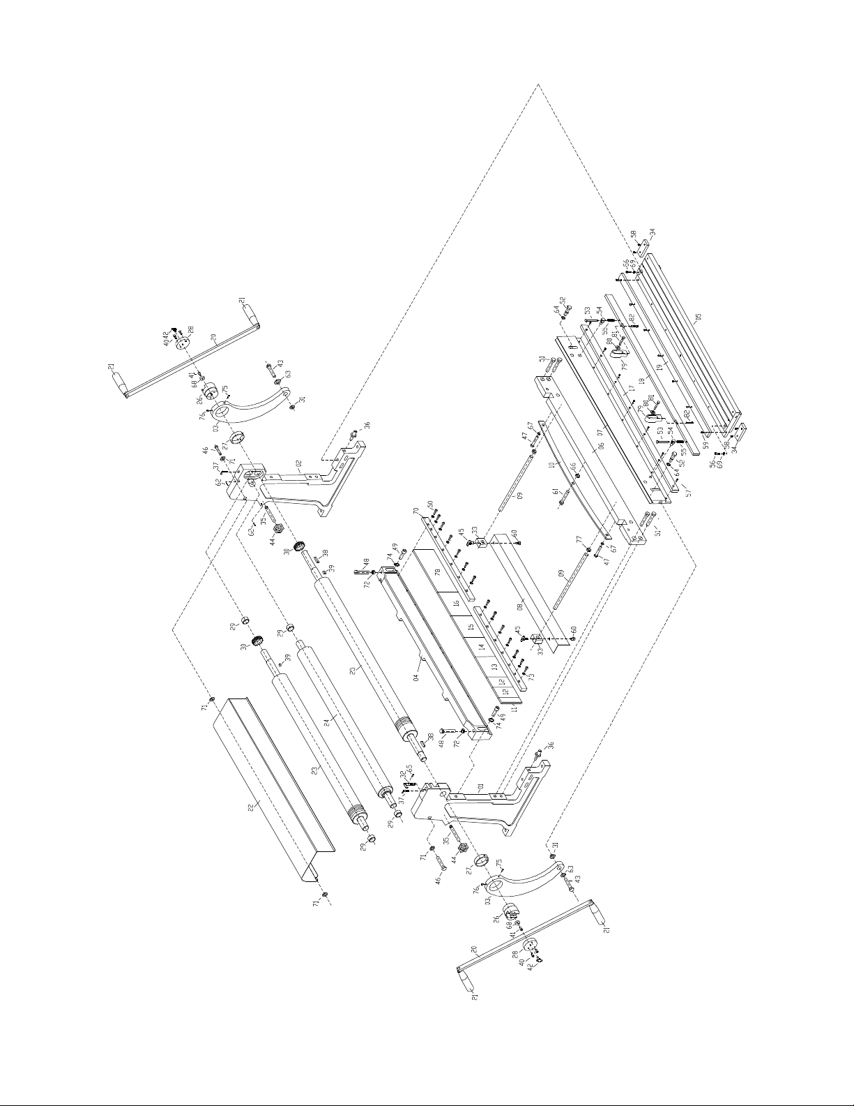
10.2.1 SBR-40M Shear/Brake/Roll – Exploded View
18
Page 19

10.2.2 SBR-40M Shear/Brake/Roll – Parts List
Index No. Part No. Description Size Qty
01 ............. SBR40M-01 .............Frame (left) .................................................. ......................................... 1
02 ............. SBR40M-02 .............Frame (right) ............................................... ......................................... 1
03 ............. SBR30M-03 .............Arm ............................................................. ......................................... 2
04 ............. SBR40M-04 .............Cross Beam ................................................ ......................................... 1
05 ............. SBR40M-05 .............Table ........................................................... ......................................... 1
06 ............. SBR40M-06 .............Spacer Bar .................................................. ......................................... 1
07 ............. SBR40M-07 .............Cutter Plate ................................................. ......................................... 1
08 ............. SBR40M-08 .............Guide Plate ................................................. ......................................... 1
09 ............. SBR40M-09 .............Guide Rod ................................................... ......................................... 1
10 ............. SBR40M-10 .............Guide Bar .................................................... ......................................... 1
11 ............. SBR30M-11 .............Brake Forming Die ....................................... 1” ...................................... 1
12 ............. SBR30M-12 .............Brake Forming Die ....................................... 2” ...................................... 2
13 ............. SBR30M-14 .............Brake Forming Die ....................................... 4” ...................................... 1
14 ............. SBR30M-15 .............Brake Forming Die ....................................... 6” ...................................... 1
15 ............. SBR40M-15 .............Brake Forming Die ....................................... 7” ...................................... 1
16 ............. SBR40M-16 .............Brake Forming Die ....................................... 8” ...................................... 1
17 ............. S BR40M-17 .............C utter .......................................................... ......................................... 1
18 ............. SBR40M-18 .............Press Plate .................................................. ......................................... 1
19 ............. S BR40M-19 .............C utter .......................................................... ......................................... 1
20 ............. SBR40M-20 .............Handle Bar .................................................. ......................................... 2
21 ............. SBR30M-21 .............Handle......................................................... ......................................... 4
22 ............. S BR40M -22 .............Co ver .......................................................... ......................................... 1
23 ............. SBR40M-23 .............Roll.............................................................. ......................................... 1
24 ............. SBR40M-24 .............Lower Press Roll ......................................... ......................................... 1
25 ............. SBR40M-25 .............Upper Press Roll ......................................... ......................................... 1
26 ............. SBR30M-2 6 .............Eccentric Shaft ............................................ ......................................... 2
27 ............. SBR30M-27 .............Bushing ....................................................... ......................................... 2
28 ............. SBR30M-2 8 .............Eccentric Cap .............................................. ......................................... 2
29 ............. SBR40M-29 .............Bushing ....................................................... ......................................... 1
30 ............. SBR40M-30 .............Gear ............................................................ ......................................... 1
31 ............. S BR30M -31 .............Pivot Bushing .............................................. ......................................... 2
32 ............. SBR40M-32 .............Thumb Screw .............................................. ......................................... 1
33 ............. SBR40M-33 .............Guide Block ................................................. ......................................... 2
34 ............. SBR40M-34 .............Block ........................................................... .................... ..................... 2
35 ............. SBR40M-3 5 .............Screw .......................................................... ......................................... 2
36 ............. SBR40M-36 .............Locating Bolt ............................................... ......................................... 2
37 ............. SBR30M-37 .............Adjustable Bolt ............................................ ......................................... 2
38 ............. SBR40M-38 .............Key.............................................................. 8x7x25mm ........................ 2
39 ............. SBR40M-39 .............Key.............................................................. 5x5x6mm .......................... 2
40 ............. TS-1503031 .............Socket Head Cap Screw .............................. M6x12 .............................. 4
41 ............. TS-1503031 .............Socket H
42 ............. SBR30M-42 .............T-Handle ..................................................... M8x25 .............................. 2
43 ............. S BR30M-43 .............H ex Cap Bolt ............................................... M12x70 ............................ 2
44 ............. SBR30M-44 .............Star Grip Knob............................................. M10 .................................. 2
45 ............. SBR30M-42 .............T-Handle ..................................................... M8x25 .............................. 2
46 ............. TS-1482081 .............Hex Cap Screw ........................................... M6x40 .............................. 2
47 ............. TS-1492021 .............Socket Head Cap Screw .............................. M12x30 ............................ 2
48 ............. TS-2211451 .............Hex Cap Screw ........................................... M12x45 ............................ 2
49 ............. TS-1506051 .............Socket Head Cap Screw .............................. M12x40 ............................ 2
50 ............. TS-1505051 .............Socket Head Cap Screw .............................. M10x35 .......................... 14
51 ............. TS-1506041 .............Socket Head Cap Screw .............................. M12x35 ............................ 4
52 ............. SBR40M-5 2 .............Screw .......................................................... ......................................... 2
53 ............. S BR30M-53 .............H ex Cap Bolt ............................................... M8x90 .............................. 2
54 ............. SBR40M-54 .............Pressure Plate Bracket ................................ ......................................... 2
55 ............. SBR40M-55 .............Spring.......................................................... ......................................... 2
56 ............. TS-1505031 .............Socket Head Cap Screw .............................. M10x25 ............................ 2
ead Cap Screw .............................. M6x12 .............................. 2
19
Page 20

Index No. Part No. Description Size Qty
57 ............. TS-1504021 .............Socket Head Cap Screw .............................. M8x12 .............................. 9
58 ............. TS-1503031 .............Socket Head Cap Screw .............................. M6x12 .............................. 4
59 ............. TS-1504021 .............Socket Head Cap Screw .............................. M8x12 .............................. 9
60 ............. TS-1504021 .............Socket Head Cap Screw .............................. M8x12 .............................. 2
61 ............. S BR40M-61 .............H ex Cap Bolt ............................................... M12x65 ............................ 1
62 ............. SBR30M-62 .............Spring Pin.................................................... 5x20mm ........................... 4
63 ............. S BR30M-63 .............P lain Washer ............................................... 12mm ............................... 2
64 ............. S BR40M-64 .............P lain Washer ............................................... 12mm ............................... 2
65 ............. TS-1524051 .............Hex Socket Set Screw ................................. M8x20 .............................. 1
66 ............. SBR30M-66 .............Adjustment Nut ............................................ M12 .................................. 1
67 ............. TS-1550071 .............Plain Washer ............................................... 10mm ............................... 2
68 ............. S BR30M -68 .............Co ver .......................................................... ......................................... 2
69 ............. S BR30M-69 .............S pecial Washer ........................................... 10mm ............................... 2
70 ............. SBR40M-70 .............Press Plate .................................................. ......................................... 2
71 ............. TS-1550041 .............Plain Washer ............................................... 6 mm ................................. 4
72 ............. S BR30M -72 .............Hex Thin Nut ............................................... M12 .................................. 2
73 ............. TS-1550071 .............Plain Washer ............................................... 1 0 mm ............................. 14
74 ............. S BR40M-74 .............S pecial Washer ........................................... 12mm ............................... 2
75 ............. SBR30M-75 .............Hex Socket Set Screw ................................. M8x20 .............................. 2
76 ............. SBR30M-76 .............Zerk Fitting .................................................. 8mm ................................. 2
77 ............. TS-154010 ...............Hex Nut ....................................................... M16 ................................ 16
78 ............. SBR40M-78 .............Brake Forming Die ....................................... 12” .................................... 1
79 ............. SBR40M-79 .............Press Plate Bracket ..................................... ......................................... 2
80 ............. S BR40M-80 .............P lain Washer ............................................... 12mm ............................... 2
81 ............. S BR40M-81 .............H ex Cap Bolt ............................................... M12x45 ............................ 2
82 ............. TS-1503071 .............Socket Head Cap Screw .............................. M6x30 .............................. 2
................. SBR40M-ID..............I.D. Label (not sho wn) .................................. ......................................... 1
................. SBR30M-WL ............Warning Label (not shown) .......................... ......................................... 1
WALTER M EIE R (Manuf a c turing) Inc.
427 New Sanford Road
LaVergne, Tennessee 37086
Phone: 800-274-6848
www.waltermeier.com
20
 Loading...