

Jet ProMac FX-383V Operating Instructions Manual

FX-383V
GB - ENGLISH
Operating Instructions
Dear Customer,
Many thanks for the confidence you have shown in us with the purchase of your new machine. This manual has been prepared
for the owner and operators of a FX-383V milling drilling centre to promote safety during installation, operation and
maintenance procedures. Please read and understand the information contained in these operating instructions and the
accompanying documents. To obtain maximum life and efficiency from your machine, and to use the machine safely, read this
manual thoroughly and follow instructions carefully.
…Table of Contents
1. Declaration of conformity
2. Warranty
3. Safety
4. Machine specifications
5. Transport and start up
6. Machine operation
7. Setup and adjustments
8. Trouble shooting
9. Environmental protection
10. Available accessories
1. Declaration of conformity
On our own responsibility we hereby declare that this product
complies with the regulations* listed on page 2. Designed in
consideration with the standards**.
2. Warranty
The Seller guarantees that the supplied product is free from
material defects and manufacturing faults. This warranty does
not cover any defects which are caused, either directly or
indirectly, by incorrect use, carelessness, accidental damage,
repair, inadequate maintenance or cleaning and normal wear
and tear.
Guarantee and/or warranty claims must be made within
twelve months from the date of purchase (date of invoice).
Any further claims shall be excluded.
This warranty includes all guarantee obligations of the Seller
and replaces all previous declarations and agreements
concerning warranties.
The warranty period is valid for eight hours of daily use. If this
is exceeded, the warranty period shall be reduced in
proportion to the excess use, but to no less than three
months.
Returning rejected goods requires the prior express consent
of the Seller and is at the Buyer’s risk and expense.
and Conditions (GTC). The GTC can be viewed at
www.jettools.com or can be sent by post upon request.
The Seller reserves the right to make changes to the product
and accessories at any time.
3. Safety
3.1 Authorized use
This milling drilling centre is designed for milling and drilling
machinable metal and plastic materials only. Machining of
other materials is not permitted and may be carried out in
specific cases only after consulting with the manufacturer.
Never cut magnesiumhigh danger to fire!
The workpiece must allow to safely be loaded and clamped
for machining.
The proper use also includes compliance with the operating
and maintenance instructions given in this manual.
The machine must be operated only by persons familiar with
its operation and maintenance and who are familiar with its
hazards.
The required minimum age must be observed.
The machine must only be used in a technically perfect
condition.
When working on the machine, all safety mechanisms and
covers must be mounted.
In addition to the safety requirements contained in these
operating instructions and your country’s applicable
regulations, you should observe the generally recognized
technical rules concerning the operation of metalworking
machines.
Any other use exceeds authorization.
In the event of unauthorized use of the machine, the
manufacturer renounces all liability and the responsibility is
transferred exclusively to the operator.
3.2 General safety notes
Metalworking machines can be dangerous if not used
properly. Therefore the appropriate general technical rules as
well as the following notes must be observed.

FX-383V
Read and understand the entire instruction manual before
attempting assembly or operation.
Keep this operating instruction close by the machine,
protected from dirt and humidity, and pass it over to the new
owner if you part with the tool.
No changes to the machine may be made.
Daily inspect the function and existence of the safety
appliances before you start the machine.
Do not attempt operation in this case, protect the machine by
unplugging the power cord.
Remove all loose clothing and confine long hair.
Before operating the machine, remove tie, rings, watches,
other jewellery, and roll up sleeves above the elbows.
Wear safety shoes; never wear leisure shoes or sandals.
Always wear the approved working outfit.
Do not wear gloves.
Wear goggles when working
Install the machine so that there is sufficient space for safe
operation and work piece handling.
Keep work area well lighted.
The machine is designed to operate in closed rooms and
must be bolted to the cabinet stand or a solid work bench.
Make sure the machine cannot tip.
Make sure that the power cord does not impede work and
cause people to trip.
Keep the floor around the machine clean and free of scrap
material, oil and grease.
Stay alert!
Give your work undivided attention. Use common sense. Do
not operate the machine when you are tired.
Keep an ergonomic body position.
Maintain a balanced stance at all times.
Do not operate the machine under the influence of drugs,
alcohol or any medication. Be aware that medication can
change your behaviour.
Never reach into the machine while it is operating or running
down.
Never leave a running machine unattended. Before you leave
the workplace switch off the machine.
Keep children and visitors a safe distance from the work
area.
Do not operate the electric tool near inflammable liquids or
gases.
Observe the fire fighting and fire alert options, for example
the fire extinguisher operation and place.
Do not use the machine in a dump environment and do not
expose it to rain.
Work only with well sharpened tools.
Always close the chuck guard and pulley cover before you
start the machine.
Remove the chuck key and wrenches before machine
operation.
Specifications regarding the maximum or minimum size of the
work piece must be observed.
Do not remove chips and work piece parts until the machine
is at a standstill.
Do not stand on the machine.
Connection and repair work on the electrical installation may
be carried out by a qualified electrician only.
Have a damaged or worn power cord replaced immediately.
Never place your fingers in a position where they could
contact any rotating tool, chuck or cutting chips.
Secure work piece against rotation. Use fixtures, clamps or a
vice to hold the work piece.
Never hold the work piece with your hands alone.
When using a vice, always fasten it to the table.
Never do any works “freehand” (hand-holding the work piece
rather than supporting it).
Never move the head while the machine is running.
If a work piece overhangs the table such that it will fall or tip if
not held, clamp it to the table or provide auxiliary support.
Check the save clamping of the work piece before starting
the machine.
Remove cutting chips with the aid of an appropriate chip hook
when the machine is at a standstill only.
Never stop the rotating chuck or tool with your hands.
Measurements and adjustments may be carried out when the
machine is at a standstill only.
Setup work may only be carried out after the machine is
protected against accidental starting by pressing the
emergency stop button.
Maintenance and repair work may only be carried out after
the machine is protected against accidental starting by pulling
the mains plug.
Do not use wire wheels or grinding wheels on this machine.
To avoid injury from parts thrown by the spring, follow
instructions exactly as given when adjusting the spring
tension of the quill (see chapter 7, Fig 11)
3.3 Remaining hazards
When using the machine according to regulations some
remaining hazards may still exist.
The rotating chuck, tool and cutting chips can cause injury.
Thrown and hot work pieces and cutting chips can lead to
injury.
Chips, dust and noise can be health hazards. Be sure to wear
personal protection gear such as safety goggles, dust mask
and ear protection.
The use of incorrect mains supply or a damaged power cord
can lead to injuries caused by electricity.
FX-383V
4. Machine specifications
4.1 Technical data
Drilling capacity 32 mm
Face milling capacity 75 mm
Motor 1,5kW
Mains supply 3~400V, PE, 50Hz
Spindle speed variable 150 – 2500 RPM
Spindle travel 150 mm
Spindle taper MT 3
Spindle diameter 75 mm
Table size 730 x 210 mm
X-Axis travel 370 mm
Y-Axis travel 170 mm
T-Slots 3 16mm
Machine dimensions
( L x W x H ) 1100 x 910 x 2100 mm
Machine weight 280 kg
4.2 Noise emission
Acoustic pressure level (EN ISO 11202):
Idling at maximum speed 73,8 dB (A)
The specified values are emission levels and are not
necessarily to be seen as safe operating levels.
As workplace conditions vary, this information is intended to
allow the user to make a better estimation of the hazards and
risks involved only.
4.3 Content of delivery
1 Milling drilling Machine
1 Machine stand
1 Coolant system
1 Operating tools
1 Operating manual
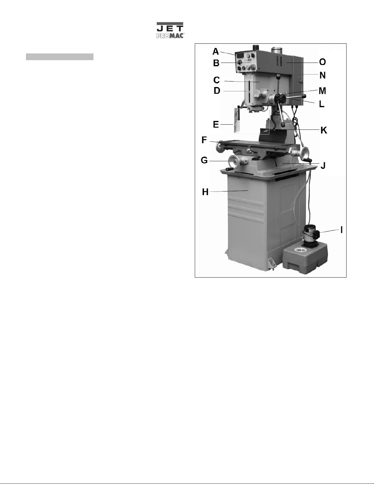
4.4 Machine Description
Fig 1
A….Digital tachometer
B….Control panel
C….Machine head
D….Depth scale
E….Safety Guard
F….Work table
G….Hand wheel
H….Stand
I…..Pump with coolant tank
J….Machine base
K….Coolant nozzle
L….Quill feed levers
M….Head lock handle
N….Electric box
O….Pulley cover
FX-383V
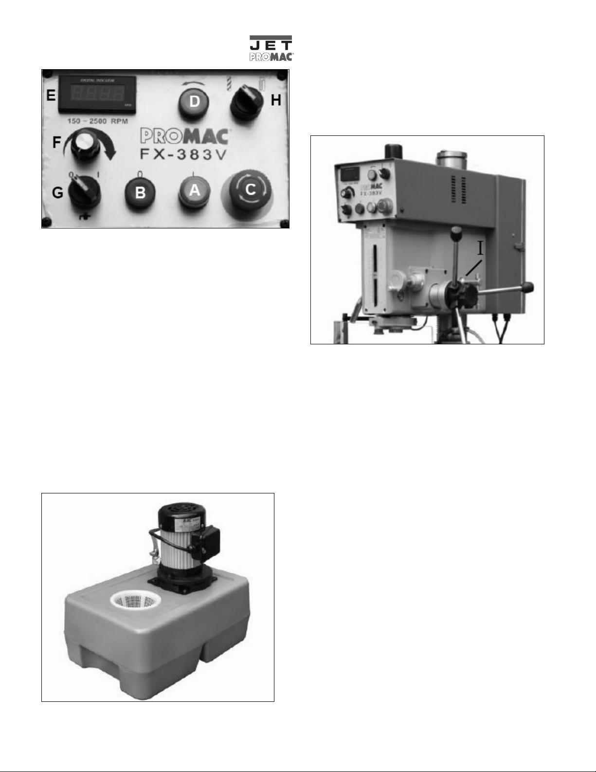
Fig 2
A. ON Switch – Starts the motor.
B. OFF Switch – Stops the motor. As the power still exists,
pressing ON will restarts the machine.
C. Emergency Stop Switch – Stops the machine
immediately. As the machine is without any power. Turn
the switch clockwise to unlock the switch before starting
the machine.
NOTE: To restart the machine, 5 to 7 seconds of waiting
is needed for the inverter to release the current.
D. Reverse Switch – Reverses the spindle rotation. Used for
executing a tapping operation.
E. Tachometer–Displays the rate of spindle rotation in RPM.
F. Spindle Speed Control knob – Changes the speed of
spindle rotation.
G. Pump Switch – Starts the coolant flow for cutting.
H. Drilling/Tapping Selector – Selects the mode of operation.
Fig 3
The coolant tank (Fig 3) holds coolant, which pumped to the
work piece for cooling and lubricating while cutting. Before
the operation of a new machine, add coolant to the coolant
tank. When iron filings clog the screen, cleaning will be
required. Before cleaning, take off the screen and drain out
the coolant.
Fig 4
The machine head (Fig 4) can be rotated 360° around the
column. It allows more flexibility in work piece sizes.
Turn off the machine.
Unlock the head handles (I–Fig. 2).
Use the riser handle to raise or lower the head. Firmly grip
the head and push left or right to rotate the head.
Lock the head handles (I).
Always keep the machine head locked after the height of
head is set as requirement.
Warning!
Failure to lock the head handles may result in damage of the
machine and personal injury.
 Loading...