

Page 1

OWNER'S MANUAL
JPB-60 & 90 Paving Breakers
WMH TOOL GROUP
Industrial Division
P.O. BOX 1349
Auburn, WA 98071-1349
Ph: 1-800-274-6848 ▪ Fax: 1-800-274-6840
E-mail: jet@wmhtoolgroup.com
www.wmhtoolgroup.com M-550075 12/02
Copyright © WMH Tool Group
Page 2

This manual has been prepared for the owner and operators of a Paving Breaker. Its purpose, aside from
machine operation, is to promote safety through the use of accepted correct operating and maintenance
procedures. Completely read the safety and maintenance instructions before operating or servicing the
machine. To obtain maximum life and efficiency from your tool, and to aid in using the machine safely,
read this manual thoroughly and follow instructions carefully.
Warranty & Service
The WMH Tool Group warrants every product it sells. If one of our tools needs service or repair, one of
our Authorized Repair Stations located throughout the United States can give you quick service.
In most cases, any one of these WMH Tool Group Repair Stations can authorize warranty repair, assist
you in obtaining parts, or perform routine maintenance and major repair on your JET, Performax, Wilton,
or Powermatic tools.
For the name of an Authorized Repair Station in your area, please call 1-800-274-6848, or visit
www.wmhtoolgroup.com
More Information
Remember, the WMH Tool Group is consistently adding new products to the line. For complete, up-todate product information, check with your local WMH Tool Group distributor, or visit
www.wmhtoolgroup.com
WMH Tool Group Warranty
The WMH Tool Group (including JET, Performax, Wilton and Powermatic brands) makes every effort to
assure that its products meet high quality and durability standards and warrants to the original retail
consumer/purchaser of our products that each product be free from defects in materials and workmanship
as follow: 1 YEAR LIMITED WARRANTY ON ALL PRODUCTS UNLESS SPECIFIED OTHERWISE.
This Warranty does not apply to defects due directly or indirectly to misuse, abuse, negligence or
accidents, normal wear-and-tear, repair or alterations outside our facilities, or to a lack of maintenance.
THE WMH TOOL GROUP LIMITS ALL IMPLIED WARRANTIES TO THE PERIOD SPECIFIED ABOVE,
FROM THE DATE THE PRODUCT WAS PURCHASED AT RETAIL. EXCEPT AS STATED HEREIN,
ANY IMPLIED WARRANTIES OR MERCHANTIBILITY AND FITNESS ARE EXCLUDED. SOME
STATES DO NOT ALLOW LIMITATIONS ON HOW LONG THE IMPLIED WARRANTY LASTS, SO THE
ABOVE LIMITATION MAY NOT APPLY TO YOU. THE WMH TOOL GROUP SHALL IN NO EVENT BE
LIABLE FOR DEATH, INJURIES TO PERSONS OR PROPERTY, OR FOR INCIDENTAL,
CONTINGENT, SPECIAL, OR CONSEQUENTIAL DAMAGES ARISING FROM THE USE OF OUR
PRODUCTS. SOME STATES DO NOT ALLOW THE EXLUSION OR LIMITATION OF INCIDENTAL OR
CONSEQUENTIAL DAMAGES, SO THE ABOVE LIMITATION OR EXCLUSION MAY NOT APPLY TO
YOU.
To take advantage of this warranty, the product or part must be returned for examination, postage
prepaid, to an Authorized Repair Station designated by our office. Proof of purchase date and an
explanation of the complaint must accompany the merchandise. If our inspection discloses a defect, we
will either repair or replace the product, or refund the purchase price if we cannot readily and quickly
provide a repair or replacement, if you are willing to accept a refund. We will return repaired product or
replacement at WMH Tool Group’s expense, but if it is determined there is no defect, or that the defect
resulted from causes not within the scope of WMH Tool Group’s warranty, then the user must bear the
cost of storing and returning the product. This warranty gives you specific legal rights; you may also have
other rights which vary from state to state.
The WMH Tool Group sells through distributors only. Members of the WMH Tool Group reserve the right
to effect at any time, without prior notice, those alterations to parts, fittings, and accessory equipment
which they may deem necessary for any reason whatsoever.
2
Page 3

WARNING
This paving breaker is designed and intended for use by properly trained and experienced
personnel only. If you are not familiar with the proper and safe operation of a paving breaker, do
not use until proper training and knowledge has been obtained.
• Always wear approved impact resistant eye protection.
• Always wear approved ear protection.
• Always wear gloves and protective clothing.
• Always direct the tool exhaust away from yourself and others.
• Always disconnect the tool from the air supply when not in use.
• Always check that the cutting chisel is securely latched in the tool before depressing the throttle
trigger.
• Always hold the cutting tool down firmly on the work before depressing the throttle trigger.
• Some dust created by power sanding, sawing, grinding, drilling and other construction activities
contains chemicals known to cause cancer, birth defects or other reproductive harm. Some
examples of these chemicals are:
• Lead from lead based paint
• crystalline silica from bricks and cement and other masonry products, and
• arsenic and chromium from chemically-treated lumber.
• Your risk from those exposures varies, depending on how often you do this type of work. To reduce
your exposure to these chemicals: work in a well ventilated area, and work with approved safety
equipment, such as those dust masks that are specifically designed to filter out microscopic particles
• Do not operate tool while under the influence of drugs, alcohol or any medication.
Specifications
Model Stock
No.
PB-60-1-1/8 550075 “T” 1-1/8”x6” 2-1/4” 5” 1,400 88.97 25-3/8” 58 3/4” 66 72
PB-60-1-1/4 550076 “T” 1-1/4”x6” 2-1/4” 5” 1,400 88.97 25-3/8” 58 3/4” 66 72
PB-90-1-1/8 550077 “T” 1-1/8”x6” 2-5/8” 6-1/2” 1,250 180.83 28-1/2” 77 3/4” 92-1/2 101
PB-90-1-1/4 550078 “T” 1-1/4”x6” 2-5/8” 6-1/2” 1,250 180.83 28-1/2” 77 3/4” 92-1/2 101
The specifications in this manual are given as general information and are not binding. JWMH Tool
Group reserves the right to effect, at any time and without prior notice, changes or alterations to parts,
fittings, and accessory equipment deemed necessary for any reason whatsoever.
Handle
Type
Shank
Size
Piston
Dia.
Piston
Stroke
Blows
per
Minute
Ft/Lb.
per Blow
@ 90 PSI
Overall
Length
CFM Air
Hose
ID
Net
lbs.
Ship
lbs.
3
Page 4
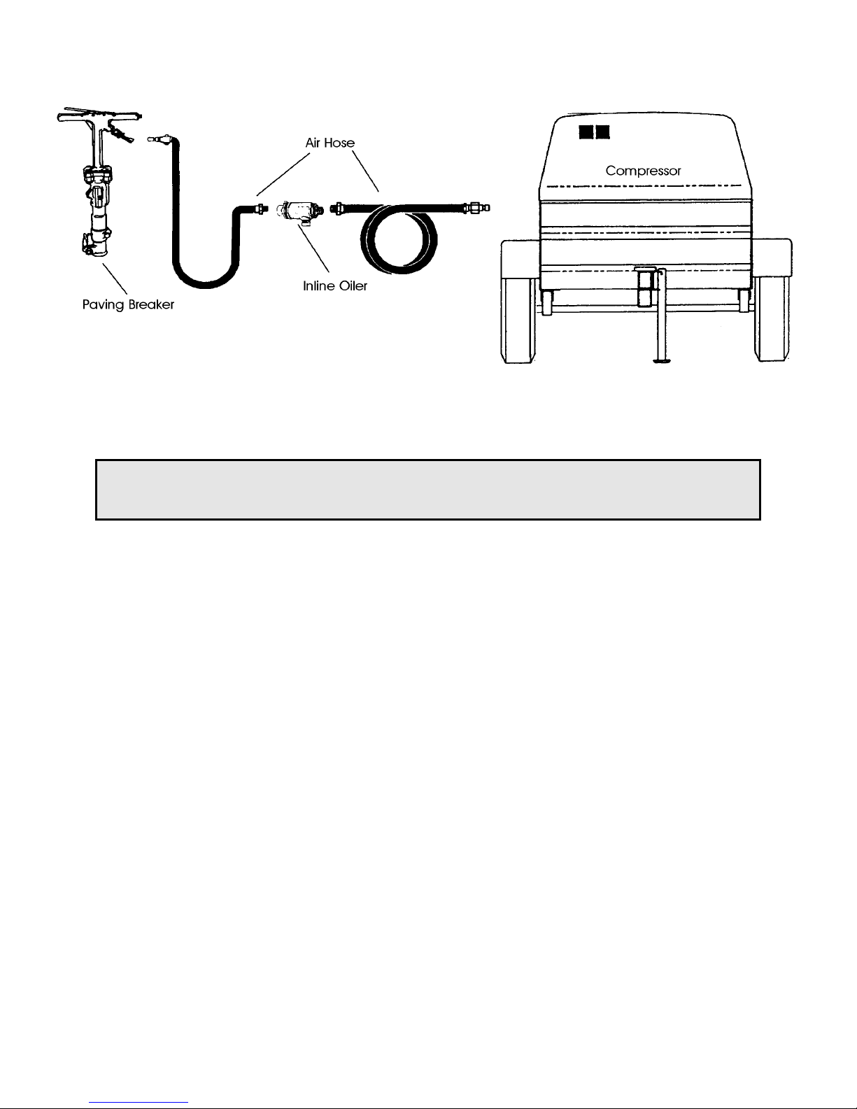
Air Hose and Connections
Daily Service
To maintain optimum tool performance, the following service is required on a daily basis:
CAUTION
Operating the tool without air lubrication, even for just a few minutes, can severely damage the
valve parts, cylinder, and piston. Such damage is not covered by your tool warranty.
• Be sure the inline oiler has lubricant and is working properly.
• Drain the air system moisture trap.
• Be sure the air pressure is regulated to no more than 90 PSI.
• Pour several ounces of JET Marvel Air Tool Oil into the tool inlet before connecting to the air supply.
• Before storing the tool, pour a few ounces of JET Marvel Air Tool Oil into the air inlet and momentarily
operate the tool.
Troubleshooting
Loss of power or erratic action:
• Compressor producing insufficient air pressure for tool.
• Compressor producing insufficient air volume for tool.
• Moisture, or debris in air hose.
• Air hose undersize, or in poor condition.
• Inadequate air system lubrication.
• Incorrect shank size.
• Excessively worn shank.
• Loose side, or back head bolts. Loose bolts can cause loss of power and tool damage. Checking
bolt torque weekly when the tool is in regular use is recommended.
• Tool is badly worn or has internal damage.
Air leakage, low impact, low bpm, tool operates with throttle off, loose chisel, steel retainer latch
does not catch:
• See Repair Notes for additional information.
4
Page 5

Disassembly
1. Disconnect the air tool from the air system.
2. Loosen the back head bolt nuts, remove the lock washer, and back head bolt nuts.
3. Remove the back head from the cylinder and remove the throttle valve, throttle valve spring, plunger,
and plunger spring.
4. Remove the valve guide, valve, valve chest, valve seat, valve chest dowel pin, and piston.
5. Remove the cylinder, tappet seat, and tappet.
6. Disassemble the front head:
• Loosen the steel retainer bolt nut.
• Remove the steel retainer bolts, the steel retainer, and the retainer bolt bushings.
• Remove the steel retainer plunger and the retainer spring.
• Remove the front head bushing from the front head by pressing it out from the backside using
a 15-ton press.
7. Disassemble the back head:
• Remove the two throttle lever pins and release the throttle lever.
• Using a press and a 0.37” (9.4mm) pin, remove the throttle valve stem guide from the back
head.
• Remove the 5/8” oil control plug from the back head and take out the oil control felt.
8. Disassemble the air inlet:
• Loosen the air inlet swivel nut and remove it from the cylinder.
• Remove the air inlet swivel.
• Remove the air inlet screen from the cylinder.
• Remove the O-ring(s) from the air inlet swivel nut and air inlet swivel.
Repair Notes
Air Leakage:
• If air is leaking from the air inlet swivel nut or air inlet swivel, change the O-rings and check for
loosening of the air inlet swivel nut.
• If air is leaking from the throttle valve area, check for wear of the throttle valve stem guide.
• If air is leaking from the back head and cylinder, check the plug carefully and change the O-ring on
the throttle valve. Also check for foreign matter, which may have entered during assembly.
Low Impact or Loss of Blows per Minute:
• Check the clearance between the pistons and the cylinder. The maximum clearance should be 0.005
in. (.13 mm). Check that the piston moves freely and is not seized.
• Check for valve seizure.
Tool continues to operate after releasing throttle lever:
• Check the throttle valve seat surface for damage. Also check for foreign material in the valve area.
Chisel is loose:
• Change the front head bushing.
Steel retainer latch does not catch
• Check for excessive steel retainer wear.
• Check for excessive steel retainer plunger and spring wear.
5
Page 6

Reassembly
Front Head Assembly
1. Using a 15-ton press, press the front head bushing into place. A hex flat must align with the front
head steel retainer.
2. Assemble the steel retainer spring and steel retainer plunger into the front head.
3. Assemble the steel retainer bolt bushings on each side of the front head. Set the retainer into the
retainer slot. To support the retainer, insert the retainer bolt through the bushings from the stopper
side of the front head.
4. Place the 3/4” nut and washer on the bolt. See the torque specifications chart for the torque setting.
Back Head Assembly
1. Place the chamfered side of the throttle valve stem guide into the back head and tap into position.
2. Ream the guide with a 0.312” (7.93 mm) reamer tool.
3. Set the throttle valve lever into the back head.
4. Place a 0.312” (7.93 mm) steel rod into the hole and hammer the pin in.
5. Apply a light film of grease on the rubber handle and slide onto the handle.
6. Assemble the plugs on both sides of the back head. See the torque specifications chart for the torque
setting.
7. Place the throttle valve o-ring in position where the cylinder will meet.
8. Insert the oil control felt onto the top portion of the back head and assemble the oil control plug.
Air Inlet Assembly
1. Place the #P91222 O-ring onto the air inlet swivel.
2. Place the #P91237 O-ring onto the air inlet swivel nut.
3. Assemble the air inlet swivel into the air inlet swivel nut and tighten the nut.
Complete Assembly
1. Stand the front head assembly in the vertical position.
2. Assemble the tappet seat and cylinder onto the front head, making sure the retainer nut and exhaust
port on the cylinder are in line with each other.
3. Place the front head bolts into the holes.
4. Assemble the front head bolt springs, front head lock washer, and tighten the front head bolt nut. A
minimum of three bolt threads should be visible.
5. Assemble the valve seat, valve, valve chest, and valve guide into the cylinder. Note: the valve chest
and valve guide must align with the knock placement. The valve has no orientation.
6. Install the valve chest dowel pin.
7. Install the five cylinder plugs into the cylinder.
8. Set the air inlet screen into the exhaust portion of the cylinder.
9. Install the air inlet assembly. See torque specification chart.
10. Place the throttle valve spring onto the throttle valve and install into the cylinder.
11. Lightly grease the inner diameter of the plunger, insert the plunger spring, and place on top of the
valve guide.
12. Place the back head on top of the cylinder and put the back head bolts from underneath into the four
holes.
13. Assemble the lock washer and fasten the back head bolt nuts. See torque specification chart for bolt
tightness.
14. Assemble the back head with the lever in line with the cylinder exhaust port.
15. Remove oil fill plug in the back head and refill the spindle oil tank.
16. Tighten oil tank plug. See torque specification chart.
17. Before operating a newly rebuilt tool, pour a few ounces of JET Marvel air tool oil into the air inlet.
6
Page 7

Torque Specifications (ft./lb.):
Refer to the chart below when assembling parts or tightening after a period of service:
Front Head Bolt
Back Head Bolt
Front Retainer Bolt
Oil Tank Bolt
GD Plug
Air Inlet Assembly
PB-60 PB-90
2-2.5mm* 3mm*
166.3-202.5 166.3-202.5
43.4-57.8 43.4-57.8
57.8 28.9-32.5
7.2-10.8 10.8-14.5
202.58-216.9 202.5-216.9
* Torque setting for the front head bolt on the PB-60 and PB-90 is given as the measurement between the
bottom of the nut and the end of the bolt.
7
Page 8

Parts Breakdown for JPB-60-1-1/8” and JPB-60-1-1/4”
8
Page 9

Parts List for JPB-60-1-1/8” and JPB-60-1-1/4”
Index Part
No. No. Description Size Qty.
1 ..........P61119..........................Oil Plug.................................................... ................................................. 1
2 ..........P61111..........................Back Head............................................... ................................................. 1
3 ..........P91245..........................Felt Oiler.................................................. 8.5x25mm ................................1
4 ..........P91220..........................Oil Control Plug ....................................... 1/2"........................................... 1
5 ..........P91217..........................Throttle Lever .......................................... ................................................. 1
6 ..........P91250..........................Spring Pin................................................ 4x40mm ...................................1
7 ..........P91252..........................Stop Lever Spring ................................... ................................................. 1
8 ..........P91251..........................Stop Lever .............................................. ................................................. 1
9 ..........P91218..........................Throttle Lever Pin....................................8x30mm ................................... 2
10 ........P91213..........................Rubber Grip............................................. ................................................. 2
11 ........P91225..........................Back Head Nut ........................................ ................................................. 4
12 ........P91224..........................Lock Washer ........................................... 5/8” ........................................... 4
13 ........P91210..........................Plunger Spring ........................................ ................................................. 1
14 ........P91209..........................Plunger.................................................... ................................................. 1
15 ........P61107..........................Valve Guide............................................. ................................................. 1
16 ........P61105..........................Valve Chest............................................. ................................................. 1
17 ........P91204..........................Automatic Valve ...................................... ................................................. 1
18 ........P61106..........................Valve Seat............................................... ................................................. 1
19 ........P91215..........................Throttle Valve Stem Guide...................... ................................................. 1
20 ........P91212..........................O-Ring.....................................................21.7x3.5mm ............................. 1
21 ........P91214..........................Throttle Valve .......................................... ................................................. 1
22 ........P91216..........................Throttle Valve Spring .............................. ................................................. 1
23 ........P91202..........................Cylinder Plug........................................... .................................................3
24 ........P91208..........................Dowel Pin ................................................ 1/4"x3/4”................................... 1
25 ........P61101..........................Cylinder ................................................... ................................................. 1
26 ........P91238..........................Air Inlet Screen ....................................... ................................................. 1
27 ........P91222..........................Air Inlet Swivel O-Ring ............................ 28.5x2mm ................................ 1
28 ........P91235..........................Air Inlet Swivel ........................................ ................................................. 1
29 ........P91237..........................O-Ring.....................................................29.4x3.1mm ............................. 1
30 ........P91236..........................Air Inlet Swivel Nut .................................. ................................................. 1
31 ........P91246..........................Plug ......................................................... ................................................. 1
32 ........P61123..........................Back Head Bolt ....................................... ................................................. 4
33 ........P61139..........................Front Head Bolt ....................................... ................................................. 2
34 ........P91244..........................Rubber Plug ............................................ ................................................. 1
35 ........P61103..........................Piston Hammer ....................................... ................................................. 1
36 ........P61126..........................Tappet Seat............................................. ................................................. 1
37 ........P61127..........................Tappet ..................................................... ................................................. 1
38 ........P61143..........................Front Head Bushing ................................ Used w/the JPB-60-1-1/8” ....... 1
............P91243 ..........................Front Head Bushing ................................ Used w/the JPB-60-1-1/4” ....... 1
39 ........P61121..........................Front Head .............................................. ................................................. 1
40 ........P91242..........................Front Head Bolt Spring ........................... ................................................. 2
41 ........P91241..........................Front Head Bolt Lock Washer................. .................................................2
42 ........P91240..........................Front Head Bolt Nut ................................ ................................................. 2
43 ........P91229..........................Steel Retainer Bolt .................................. ................................................. 1
44 ........P91232..........................Steel Retainer Bolt Bushing .................... ................................................. 2
45 ........P91231..........................Lock Washer ........................................... 3/4"........................................... 1
46 ........P91230..........................Steel Retainer Bolt Nut ........................... 3/4"-16 ..................................... 1
47 ........P91234..........................Steel Retainer Spring.............................. ................................................. 1
48 ........P91233..........................Steel Retainer Plunger............................ ................................................. 1
49 ........P91228..........................Steel Retainer ......................................... ................................................. 1
9
Page 10

Parts Breakdown for JPB-90-1-1/8” and JPB-90-1-1/4”
10
Page 11

Parts List for JPB-90-1-1/8” and JPB-90-1-1/4”
Index Part
No. No. Description Size Qty.
1 ..........P91213..........................Rubber Grip............................................. ................................................. 2
2 ..........P91211..........................Back Head............................................... ................................................. 1
3 ..........P91220..........................Oil Control Plug ....................................... 1/8”........................................... 1
4 ..........P91245..........................Felt Oiler.................................................. 8.5x25mm ................................1
5 ..........P91217..........................Throttle Lever .......................................... ................................................. 1
6 ..........P91250..........................Spring Pin................................................ 4x40mm ...................................1
7 ..........P91251..........................Stop Lever............................................... ................................................. 1
8 ..........P91252..........................Stop Lever Spring ................................... ................................................. 1
9 ..........P91218..........................Throttle Lever Pin....................................8x30mm ................................... 2
10 ........P91248..........................Oil Tank Plug........................................... 1/2"...........................................2
11 ........P91225..........................Back Head Nut ........................................ ................................................. 4
12 ........P91224..........................Lock Washer ........................................... 5/8” ........................................... 4
13 ........P91219..........................Oil Plug.................................................... ................................................. 1
14 ........P91210..........................Plunger Spring ........................................ ................................................. 1
15 ........P91209..........................Plunger.................................................... ................................................. 1
16 ........P91208..........................Dowel Pin ................................................ 1/4"x3/4”................................... 1
17 ........P91207..........................Valve Guide............................................. ................................................. 1
18 ........P91205..........................Valve Chest............................................. ................................................. 1
19 ........P91204..........................Automatic Valve ...................................... ................................................. 1
20 ........P91206..........................Valve Seat............................................... .................................................1
21 ........P91215..........................Throttle Valve Stem Guide...................... ................................................. 1
22 ........P91212..........................O-Ring.....................................................21.7x3.5mm ............................. 1
23 ........P91214..........................Throttle Valve .......................................... ................................................. 1
24 ........P91216..........................Throttle Valve Spring .............................. ................................................. 1
25 ........P91202..........................Cylinder Plug........................................... .................................................5
26 ........P91201..........................Cylinder .................................................. ................................................. 1
27 ........P91238..........................Air Inlet Screen ....................................... ................................................. 1
28 ........P91222..........................Air Inlet Swivel O-Ring ............................ 28.5x2mm ................................ 1
29 ........P91235..........................Air Inlet Swivel ........................................ ................................................. 1
30 ........P91237..........................O-Ring.....................................................29.4x3.1mm ............................. 1
31 ........P91236..........................Air Inlet Swivel Nut .................................. ................................................. 1
32 ........P91246..........................Plug ......................................................... ................................................. 1
33 ........P91223..........................Back Head Bolt ....................................... ................................................. 4
34 ........P91239..........................Front Head Bolt ....................................... ................................................. 2
35 ........P91244..........................Rubber Plug ............................................ ................................................. 1
36 ........P91203..........................Piston Hammer ....................................... ................................................. 1
37 ........P91226..........................Tappet Seat............................................. ................................................. 1
38 ........P91227..........................Tappet ..................................................... ................................................. 1
39 ........P61143..........................Front Head Bushing ................................ Used w/the JPB-90-1-1/8” ....... 1
............P91243 ..........................Front Head Bushing ................................ Used w/the JPB-90-1-1/4” ....... 1
40 ........P91221..........................Front Head .............................................. ................................................. 1
41 ........P91242..........................Front Head Bolt Spring ........................... ................................................. 2
42 ........P91241..........................Front Head Bolt Lock Washer................. .................................................2
43 ........P91240..........................Front Head Nut ....................................... ................................................. 2
44 ........P91229..........................Steel Retainer Bolt .................................. ................................................. 1
45 ........P91232..........................Steel Retainer Bolt Bushing .................... ................................................. 2
46 ........P91231..........................Lock Washer ........................................... 3/4"........................................... 1
47 ........P91230..........................Steel Retainer Bolt Nut ........................... 3/4"-16 ..................................... 1
48 ........P91234..........................Steel Retainer Spring.............................. ................................................. 1
49 ........P91233..........................Steel Retainer Plunger............................ ................................................. 1
50 ........P91228..........................Steel Retainer ........................................ ................................................. 1
11
 Loading...