

JET L-100-1000-10, L-100-1000-20, L-100-1000-30, L-100-150WO-10, L-100-100-10 Operating Instructions and Parts Manual
...Page 1

Operating Instructions and Parts Manual
L-100 Series Hand Chain Hoists
WALTER MEIER (Manufacturing), Inc.
427 New Sanford Road
LaVergne, Tennessee 37086 Part No. M-106210
Ph.: 800-274-6848 Revision B 04/2010
www.waltermeier.com Copyright © 2010 Walter Meier (Manufacturing) Inc.
Page 2

Warranty and Service
Walter Meier (Manufacturing) Inc., warrants every product it sells. If one of our tools needs service or repair, one of
our Authorized Service Centers located throughout the United States can give you quick service. In most cases, any
of these Walter Meier Authorized Service Centers can authorize warranty repair, assist you in obtaining parts, or
®
perform routine maintenance and major repair on your JET
your area call 1-800-274-6848.
MORE INFORMATION
Walter Meier is consistently adding new products to the line. For complete, up-to-date product information, check with
your local Walter Meier distributor, or visit waltermeier.com.
WARRANTY
JET products carry a limited warranty which varies in duration based upon the product (MW = Metalworking, WW =
Woodworking).
WHAT IS COVERED?
This warranty covers any defects in workmanship or materials subject to the exceptions stated below. Cutting tools,
abrasives and other consumables are excluded from warranty coverage.
WHO IS COVERED?
This warranty covers only the initial purchaser of the product.
WHAT IS THE PERIOD OF COVERAGE?
The general JET warranty lasts for the time period specified in the product literature of each product.
WHAT IS NOT COVERED?
Five Year Warranties do not cover woodworking (WW) products used for commercial, industrial or educational
purposes. Woodworking products with Five Year Warranties that are used for commercial, industrial or education
purposes revert to a One Year Warranty. This warranty does not cover defects due directly or indirectly to misuse,
abuse, negligence or accidents, normal wear-and-tear, improper repair or alterations, or lack of maintenance.
HOW TO GET SERVICE
The product or part must be returned for examination, postage prepaid, to a location designated by us. For the name
of the location nearest you, please call 1-800-274-6848.
You must provide proof of initial purchase date and an explanation of the complaint must accompany the
merchandise. If our inspection discloses a defect, we will repair or replace the product, or refund the purchase price,
at our option. We will return the repaired product or replacement at our expense unless it is determined by us that
there is no defect, or that the defect resulted from causes not within the scope of our warranty in which case we will,
at your direction, dispose of or return the product. In the event you choose to have the product returned, you will be
responsible for the shipping and handling costs of the return.
HOW STATE LAW APPLIES
This warranty gives you specific legal rights; you may also have other rights which vary from state to state.
LIMITATIONS ON THIS WARRANTY
WALTER MEIER (MANUFACTURING) INC., LIMITS ALL IMPLIED WARRANTIES TO THE PERIOD OF THE
LIMITED WARRANTY FOR EACH PRODUCT. EXCEPT AS STATED HEREIN, ANY IMPLIED WARRANTIES OR
MERCHANTABILITY AND FITNESS ARE EXCLUDED. SOME STATES DO NOT ALLOW LIMITATIONS ON HOW
LONG THE IMPLIED WARRANTY LASTS, SO THE ABOVE LIMITATION MAY NOT APPLY TO YOU.
WALTER MEIER SHALL IN NO EVENT BE LIABLE FOR DEATH, INJURIES TO PERSONS OR PROPERTY, OR
FOR INCIDENTAL, CONTINGENT, SPECIAL, OR CONSEQUENTIAL DAMAGES ARISING FROM THE USE OF
OUR PRODUCTS. SOME STATES DO NOT ALLOW THE EXCLUSION OR LIMITATION OF INCIDENTAL OR
CONSEQUENTIAL DAMAGES, SO THE ABOVE LIMITATION OR EXCLUSION MAY NOT APPLY TO YOU.
Walter Meier sells through distributors only. The specifications in Walter Meier catalogs are given as general
information and are not binding. Members of Walter Meier reserve the right to effect at any time, without prior notice,
those alterations to parts, fittings, and accessory equipment which they may deem necessary for any reason
®
whatsoever. JET
branded products are not sold in Canada by Walter Meier.
tools. For the name of an Authorized Service Center in
2
Page 3

Table of Contents
Warranty and Service .............................................................................................................................. 2
Table of Contents .................................................................................................................................... 3
Introduction ............................................................................................................................................. 3
Warning ................................................................................................................................................... 4
Specifications .......................................................................................................................................... 5
Using the Chain Hoist .............................................................................................................................. 6
Prior to Operation ................................................................................................................................. 6
Hooking the Load ................................................................................................................................. 7
Raising the Load .................................................................................................................................. 7
Hand Chain – Cutting and Installing ......................................................................................................... 8
Load Chain and Bottom Hook .................................................................................................................. 9
Load Chain Inspection (all models) ....................................................................................................... 9
Load Chain Removal (all models) ......................................................................................................... 9
Load Chain and Bottom Hook Installation .............................................................................................. 10
Chain Installation – 0.5- to 2-Ton Hoists ............................................................................................. 10
Chain Installation – 3- to 5-Ton Hoists ................................................................................................ 10
Chain Installation – 10- to 20-Ton Hoists ............................................................................................ 11
Attaching Load Chain to Load Chain Sprocket (all models) ................................................................... 9
Inspection and Maintenance .................................................................................................................. 12
Load Limits ............................................................................................................................................ 13
Load Chain ........................................................................................................................................ 13
Hooks (Top & Bottom) .................................................................................................................... 13
Replacement Parts ................................................................................................................................ 13
Parts List: L100-25 Chain Hoist (0.25 Ton) ......................................................................................... 14
Parts List: L100-50 Chain Hoist (0.5 Ton) ........................................................................................... 16
Parts List – L100-100 Chain Hoist (1 Ton) .......................................................................................... 18
Parts List – L100-150 Chain Hoist (1.5 Ton) ....................................................................................... 20
Parts List – L100-200 Chain Hoist (2 Ton) .......................................................................................... 22
Parts List – L100-300 Chain Hoist (3.0 Ton) ....................................................................................... 24
Parts List – L100-500 Chain Hoist (5 Ton) .......................................................................................... 26
Parts List – L100-1000 Chain Hoist (10 Ton) ...................................................................................... 28
Parts List – L100-1500 Chain Hoist (15 Ton) ...................................................................................... 30
Parts List – L100-2000 Chain Hoist (20 Ton) ...................................................................................... 32
L-100 Chain Hoist Parts Breakdown ................................................................................................... 34
Introduction
This manual is provided by Walter Meier (Manufacturing) Inc., covering the safe operation and
maintenance procedures for a JET Model L-100 Series Chain Hoist. This manual contains instructions on
installation, safety precautions, general operating procedures, maintenance instructions and parts
breakdown. This tool has been designed and constructed to provide years of trouble free operation if
used in accordance with instructions set forth in this manual. If there are any questions or comments,
please contact either your local supplier or Walter Meier. Walter Meier can also be reached at our web
site: www.waltermeier.com.
3
Page 4

Warning
1. Read and understand the entire owners manual before attempting assembly or operation.
2. Read and understand the warnings posted on the tool and in this manual. Failure to comply with all of
these warnings may cause serious injury and/or damage to property.
3. Replace the warning labels if they become obscured or are missing.
4. Keep visitors a safe distance from the work area. Keep children away.
5. Give your work undivided attention. Looking around, carrying on a conversation and “horse-play” are
careless acts that can result in serious injury.
6. This chain hoist is designed and intended for use by properly trained and experienced personnel only.
If you are not familiar with the proper and safe operation of a chain hoist, do not use until proper
training and knowledge have been obtained.
7. Do not use this chain hoist for other than its intended use. If used for other purposes, Walter Meier
(Manufacturing) Inc., disclaims any real or implied warranty and holds itself harmless from any injury
that may result from that use.
8. Do not use to lift people or loads over people.
9. Do not exceed the rated capacity of the chain hoist.
10. Do not use more than hand power to pull the hand chain.
11. Do not use the load chain as a sling; this may cause damage to the chain.
12. Always inspect the chain hoist for damage prior to use. If the chain hoist is damaged, do not use until
it has been repaired or replaced.
13. Do not use more than one chain hoist to lift or move a load. If this is unavoidable, each chain hoist
must have the same capacity as the load to be moved.
14. Never allow the load chain to “set” over sharp edges. All lifts must be made with straight chain that is
free of obstacles.
15. If the hand chain is difficult to operate, then the load exceeds the capacity of the chain hoist. Select a
chain hoist of larger capacity.
16. Do not use a chain hoist unless load is centered between top and bottom hooks.
17. Always take time to study the job to be performed and choose the safest method. Do not place
yourself or other people in an unsafe position.
18. Leave all internal maintenance to a qualified Walter Meier repair station.
19. Replace the chain with factory replacement chain only. Do not use any other type of chain.
20. Never use the chain hoist if either hook is stretched, deformed, or has a broken or missing safety
latch. Always replace the safety latch and/or the hook before placing the chain hoist back into service.
21. Understand and follow all procedures as set forth in American National Standards titled “Performance
Standard for Hand Chain Manually Operated Chain Hoists.” ANSI/ASME HST-2M. This standard is
available through the American Society of Mechanical Engineers, 345 East 47
th
St., NY, NY 10017.
(www.asme.org)
Familiarize yourself with the following safety notices used in this manual:
This means that if precautions are not heeded, it may result in minor injury and/or
possible tool damage.
This means that if precautions are not heeded, it may result in serious injury or possibly
even death.
4
Page 5

Specifications
5
Page 6

Using the Chain Hoist
Prior to Operation
1. Support for the hoist may be hook, clevis pin,
trolley, or beam clamp. Whatever method of
suspension is chosen, the support components
must be rated equal to, or greater than the
capacity of the chain hoist.
2. If the chain hoist has not been used for an
extended period of time, check for proper
operation before putting into service.
3. The brake mechanism must be kept clean and
free from dirt, water, and oil. Never allow oil to
penetrate the brake mechanism. Always keep
your chain hoist clean and store in a clean, dry
location.
4. Although oiling the chain is not mandatory, a
light coat of 30-weight oil applied periodically to
the chain will create easier operation and
prolong the life of the chain.
5. Check the chain for damage and elongation.
Replace damaged chain before using the chain
hoist.
The load chain supplied with your JET chain hoist
is designed, manufactured, and tested for proper fit
and durability. Over a period of time, the chain may
need to be replaced. For your own safety, use
factory replacement chain only.
Use of other than factory
replacement chain may cause serious injury
and/or damage to the hoist.
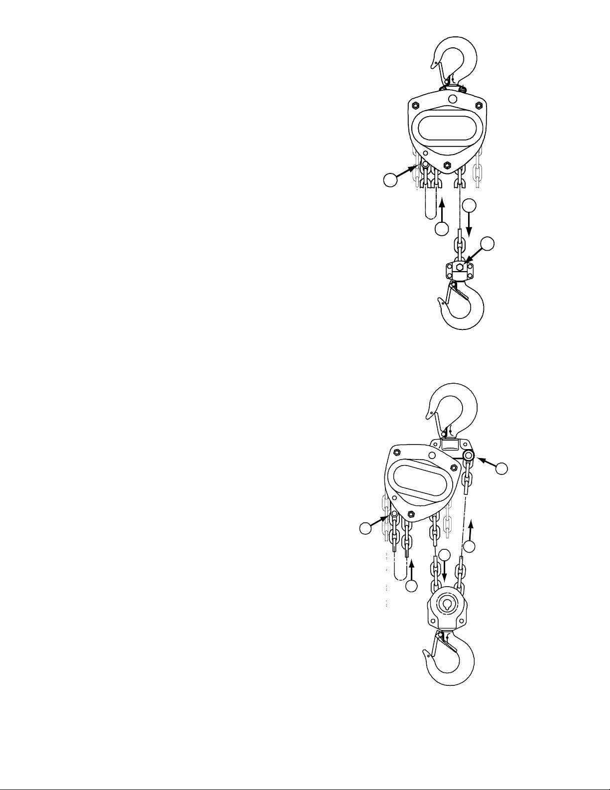
6. The top and bottom hooks on your JET chain
hoist are designed to open to warn of an
overload. Both top and bottom hooks for 0.5 to
5 ton hoists have two indicator points (A, Figure
1) cast into the hook for measurement. Refer to
Table 2 (page 13) to determine if a hook needs
to be replaced.
Hooks for 10- and 20-ton hoists do not have
indicator points. Measurements are made at
the jaw opening (B, Figure 1).
7. It is important to check top and bottom hooks
for proper opening. If the safety latch no longer
contacts the hook opening, replace the hook.
Never side load the top or bottom hook; this
practice is dangerous and could lead to
serious injury.
8. If the vertical angle at the neck of the bottom or
top hook reaches 10°, replace the hook (see
Figure 2).
Figure 1
Figure 2
6
Page 7

Hooking the Load
1. Secure the upper hook.
2. Place the bottom hook securely into the object
to be lifted.
3. Place ropes or chain in the center of the bottom
hook, making sure the safety latch is secure.
Never load the hook in front of the safety latch.
See Figure 3.
4. Avoid lifting one load with two hoists. If this is
unavoidable, apply equal weight to both hoists
and use hoists with the proper lift capacity.
Capacity of each hoist must be equal to the
total load to be lifted.
5. Check that the chain is not twisted at the
bottom hook. All welds should face the same
direction (Figure 4).
6. For hoists with two or more falls of chain, make
sure the bottom hook is not turned over. This
may cause the chain to twist.
Raising the Load
To raise the load, pull the right side of the hand
chain (A, Figure 5) clockwise.
Figure 3
Figure 4
To lower the load, pull the left side of the hand
chain (B, Figure 5) counterclockwise.
Important: Make sure the hoist has an adequate
length of load chain to raise or lower the load in a
safe manner. Do not attempt to lower the hoist
beyond its limit.
Figure 5
7
Page 8

Hand Chain – Cutting and
Installing
To cut the hand chain in order to increase or
shorten:
To change the length of the hand chain, the chain
must be cut and links added to increase the overall
length or links removed to decrease the length.
This is done as follows:
1. Insert one link lengthwise into the vise (Figure
6). Be sure that the side opposite the weld lies
completely below the surface of the vise jaw
(about 1/3 of a link). This prevents nicking or
cutting the lower part of the link.
2. Using a hack saw, cut through the upper part of
the link at the weld.
3. Loosen the link, reposition the link vertically at
the edge of the vise with the level of the cut
above the vise jaw (Figure 7).
4. Tighten the vise jaw.
5. Using an adjustable wrench, twist the link
horizontally from front to back. (Figure 8) Open
just far enough to insert (or remove) a second
chain link.
Figure 6
Figure 7
Note: Chain length is now ready to lengthen or
shorten.
6. Insert or remove the second end link at the
opening in the first end link.
7. Using an adjustable wrench, twist the link
horizontally until the link is in the original closed
position. See Figure 9.
Do not push the link inward
from the curved ends. This will distort the link.
Check that the link is closed and free of twist.
8. If installing entire new chain, insert the end of
the hand chain into the groove at the top of the
hand chain wheel (see Figure 10). Rotate the
hand chain wheel and pull the chain through.
9. Re-weld the link at the cut.
10. Grind off excess on the weld so that it is
smooth.
Figure 8
Figure 9
8
Page 9

Load Chain and Bottom Hook
Load Chain Inspection (all models)
Over time, the load chain will wear or elongate.
This can cause damage to the hoist, breakage, or
non-engagement of the load sheave.
Do not operate the hoist with a
twisted, kinked or damaged load chain. Do not
splice the load chain. Check the chain for
excessive wear or stretch. Failure to comply
may cause serious injury.
1. Test the hoist under load in both the lifting and
lowering directions, observing the operation of
chain and sprockets. Chain should feed
smoothly into and away from the sprockets.
2. If the chain binds, jumps, or is noisy, make sure
it is clean and properly lubricated. If the trouble
persists, inspect the chain and mating parts for
wear, distortion, or other damage.
3. Clean the chain before inspection. Examine for
gouges, nicks, weld splatter, corrosion, and
distorted links. Slacken the chain and move
adjacent links to one side, looking for wear at
the contact points. If you see wear or suspect
stretching, measure the chain as follows:
Attaching Load Chain to Load Chain
Sprocket (all models)
Install the new load chain onto the load chain
sprocket as follows , referring to Fig. 10:
1. Position the load chain sprocket by rotating the
hand chain wheel so that the wide and narrow
grooves show.
2. Insert the load chain into the sprocket grooves
so that the chain will wind up and back over the
sprocket. Welds must face away from the
sprocket.
3. Rotate the hand chain wheel so that the load
chain falls six to eight inches at the back of the
sprocket.
• Select an unworn, unstretched length of
chain (i.e. at the slack end).
• Suspend the chain vertically under tension
and, using a caliper type gauge, measure
the outside length of several links about 12
to 24 inches.
• Measure the same number of links in used
sections and calculate the percentage of
the increase in length.
4. If the length of used chain exceeds 2-1/2
percent of the unused chain, replace the chain.
(See “Load Limits” on page 13 for specific link
measurements.)
Do not add to the load chain.
Replace the entire chain. Failure to comply may
cause serious injury.
Load Chain Removal (all models)
Remove the old load chain as follows while
referring to Figure 11:
1. Remove the cotter pin (A) and the chain anchor
pin (C) on the chain anchor (D), allowing the
end of the chain to fall free.
2. Pull the hand chain (Fig. 5) until the load chain
is completely removed from the gear assembly.
Figure 10
Referring to Figure 11:
4. Insert one end of the chain link (B) into the
chain anchor (D).
5. Insert the chain anchor pin (C) through the
chain anchor (D) and chain link (B) and secure
with the cotter pin (A).
Figure 11
Continue with Load Chain and Bottom Hook
Installation on the following page, proceeding to the
section that applies to your hoist: 1/2- to 2-Ton
hoists, 3- to 5-Ton hoists, or 10- to 20-Ton Hoists.
9
Page 10
Load Chain and Bottom Hook
Installation
The following procedure assumes that the load
chain has been attached to the chain anchor (A,
Figure 12) and fed through the load chain sprocket
as described in the previous section. This section
completes the load chain and bottom hook
installation.
A
Chain Installation – 0.5- to 2-Ton Hoists
Referring to Figure 12:
1. Remove the lock nut and bolt from the lower
hook (D).
2. Insert the last chain link (C) into the lower hook
slot.
3. Re-insert the bolt through the lower hook slot
and chain link.
4. Re-attach the lock nut to the bolt and tighten.
Chain Installation – 3- to 5-Ton Hoists
Referring to Figure 13:
1. After installing the load chain into the load
chain sprocket (B), run the remaining chain
through your hand to remove any twist. The
last link of the chain must be in the same
direction as the first. If not, cut off the last link.
C
B
D
0.5 to 2 Ton
Figure 12
E
2. Insert the last link into the pulley of the lower
hook (C).
3. Pull the load chain through and up from the
underside of the pulley (C, D).
4. Remove the cotter pin and chain anchor pin in
the upper hook slot (E).
5. Insert the last link into the upper hook slot.
6. Check that the load chain is not twisted.
7. Re-position the chain anchor pin back through
the upper hook slot and the last chain link and
secure with the cotter pin.
A
D
C
B
3 to 5 Ton
Figure 13
10
Page 11

Chain Installation – 10- to 20-Ton Hoists
Referring to Figure 14:
1. After installing the load chain into the load
chain sprocket (B), run the remaining chain
through your hand to remove any twist. The
last link of the chain must be in the same
direction as the first. If not, cut off the last link.
2. Insert the last link into the left side pulley of the
lower hook (C).
3. Pull the load chain through and up from the
underside of the pulley (C, D).
4. Insert the last link into the right hand pulley of
the upper hook, moving the chain up, then
around and down (D, E). Check that the load
chain is not twisted and welds face away from
the pulley.
5. Insert the last link into the right side pulley of
the lower hook, pulling around, then up from
the underside of the pulley (E, F). Check that
the load chain is not twisted and welds face
away from the pulley.
6. Remove the cotter pin and chain anchor pin in
the upper hook slot (G).
7. Insert the last link into the upper hook slot.
8. Check that the load chain is not twisted.
Re-position the chain anchor pin back through the
upper hook slot and the last chain link and secure
with the cotter pin.
G
A
C
D
B
E
F
10 Ton
Figure 14
11
Page 12

Inspection and Maintenance
Read and follow ANSI Inspection and
Maintenance Instructions. Know the meaning of
Frequent Inspection, Periodic Inspection,
Normal Service, Heavy Service, and Severe
Service. It is the customer’s responsibility to
understand and follow all ANSI and JET
inspection and maintenance instructions.
All repairs and adjustments
are to be performed by trained and
experienced personnel using procedures
that are approved for the hoist system being
serviced. Failure to comply may cause
serious injury.
All safety related deficiencies
discovered in the inspection are to be
corrected before the hoist is to be placed
back into service. Failure to comply may
cause serious injury.
Check for internal damage
whenever external damage has occurred.
Failure to comply may cause serious injury.
1. Clean hoist after each use and oil lightly.
2. Do not drop or drag the hoist.
3. Store the hoist in a clean and dry
environment.
4. Chain oiling is not mandatory but will
increase the life of the chain.
5. Leave all repairs and adjustments of internal
parts to qualified repair personnel.
6. Inspect the load chain and the lower hook
after lifting a maximum weight load.
7. This hoist uses special alloy hoisting chain
and does not interchange with any other
manufacturer. All replacement chain must
be purchased from your JET distributor or
from Walter Meier (Manufacturing) Inc.,
directly by calling 800-274-6848.
8. Check and inspect the brake system
frequently.
9. Annually, the hoist should be disassembled,
inspected, and cleaned by trained and
experienced personnel only. Contact a
Walter Meier authorized service center by
calling your dealer or visiting our web site at
waltermeier.com.
10. After servicing, test the hoist with no load,
then test the hoist with a load.
12
Page 13

Load Limits
Load Chain
Capacity
0.25 ton 2.36” 2.43"
0.5 ton 2.95” 3.04"
1 ton 3.74” 3.85"
1.5 ton 4.13” 4.25"
2 ton 4.72” 4.86"
3 ton 4.13” 4.25"
5 ton 5.31” 5.47"
10 ton 5.31” 5.47"
15 ton 5.31” 5.47"
20 ton 5.31” 5.47"
Carefully inspect the entire load chain. As
illustrated in Figure 15, measure five consecutive
links with callipers to measure the length. Check
every three feet and especially where excessive
wear is indicated. Any load chain that shows
noticeable deformation or heat influence must be
replaced with a new one. Never extend load chain
by welding a second piece to the original.
5 Links
Normal
Table 1
5 Links
Limit
Hooks (Top & Bottom)
Capacity
0.25 ton 1.39” 1.47” -- --
0.5 ton 1.36" 1.44" -- -1 ton 1.77" 1.88" -- --
1.5 ton 1.86" 1.97" -- -2 ton 2.05" 2.17" -- -3 ton 2.45" 2.60" -- -5 ton 3.06" 3.24" -- --
10 ton -- -- 2.52" 2.67"
15 ton -- -- 3.15” 3.34”
20 ton -- -- 3.23” 3.42”
See Figure 16. Replace the hook when the “A”
measurement is wider than “A” Limit in the table
above. Never heat-treat the hook or attach anything
to the hook by welding.
“A”
Norm
“A”
Limit
Table 2
“B”
Norm
“B”
Limit
Figure 15
A
B
Figure 16
Replacement Parts
Replacement parts are listed on the following pages. To order parts or reach our service department, call
1-800-274-6848, Monday through Friday (see our website for business hours, www.waltermeier.com).
Having the Model Number and Serial Number of your machine available when you call will allow us to
serve you quickly and accurately.
13
Page 14

Parts List: L100-25 Chain Hoist (0.25 Ton)
Parts listed under each assembly are parts that make up that assembly. Sold as an assembly only.
Index No. Part No. Description Size Qty
1 ............... L100-25-1 ................Top Hook Assembly .............................................................................. 1
................. ................................Top Hook .............................................................................................. 1
................. ................................Safety Latch .......................................................................................... 1
................. ................................Double Spring........................................................................................ 1
................. ................................Socket Head Cap Screw .....................................M4x20 ........................ 1
................. ................................Lock Nut .............................................................M4 .............................. 1
................. ................................Top Hook Holder ................................................................................... 1
................. ................................Rivet ...................................................................4x14 mm .................... 2
2 ............... L100-25-2 ................Safety Latch Assembly .......................................................................... 2
................. ................................Safety Latch .......................................................................................... 2
................. ................................Double Spring........................................................................................ 2
................. ................................Socket Head Cap Screw .....................................M4x20 ........................ 2
................. ................................Lock Nut .............................................................M4 .............................. 2
3 ............... L100-25-3 ................Top Hook Shaft ..................................................................................... 1
4 ............... L100-25-4 ................Split Pin ..............................................................2.5x20 mm ................. 1
5 ............... L100-25-5 ................Bottom Hook Assembly ......................................................................... 1
................. ................................Bottom Hook ......................................................................................... 1
................. ................................Safety Latch .......................................................................................... 1
................. ................................Double Spring........................................................................................ 1
................. ................................Socket Head Cap Screw .....................................M4x20 ........................ 1
................. ................................Lock Nut .............................................................M4 .............................. 1
................. ................................Rivet ...................................................................5x20 mm .................... 2
6 ............... L100-25-6 ................Bottom Hook Shaft ................................................................................ 1
7 ............... TS-1541011 .............Lock Nut .............................................................M5 .............................. 1
8 ............... L100-25-8 ................Hand Wheel Cover Assembly ................................................................ 1
................. ................................Hand Wheel Cover ................................................................................ 1
................. ................................Hand Chain Guide ................................................................................. 2
8A ............ L100-25-8A ..............Warning Label ....................................................................................... 1
9 ............... L100-25-9 ................Positional Collar .................................................................................... 1
................. L100-25-9-1 .............Wheel Stopper (Available from 2010-02-01) .......M6 .............................. 1
10 ............. L100-25-10 ..............Pin......................................................................................................... 1
................. L100-25-10-1 ...........Wheel Washer (Available from 2010-02-01) ........................................... 1
11 ............. L100-25-11 ..............Split Pin (Cancelled from 2010-02-01) ................1.5x15 mm ................. 1
12 ............. L100-25-12 ..............Hand Chain – specify length ...............................3x15 mm .................... 1
13 ............. L100-25-13 ..............Hand Chain Connecting Link ................................................................. 1
14 ............. L100-25-14 ..............Hand Chain Wheel ................................................................................ 1
................. L100-25-14-1 ...........Hand Chain Wheel (Available from 2010-02-01) .................................... 1
14L ........... L100-25WO-14L ......Overload Limiter Assembly (used on overload protection model)............ 1
................. ................................Overload Limiter Knob ........................................................................... 1
................. ................................Brake Disc ............................................................................................. 2
................. ................................Hand Chain Wheel ................................................................................ 1
................. ................................Bushing in Hand Chain Wheel ............................................................... 1
................. ................................Disc Spring Plate ................................................................................... 1
................. ................................Disc Spring ............................................................................................ 1
................. ................................Disc Spring Stopper ............................................................................... 1
................. ................................Lock Nut ................................................................................................ 1
15 ............. L100-25-15 ..............Snap Ring ..........................................................5 mm .......................... 2
16 ............. L100-25-16 ..............Pawl ...................................................................................................... 2
17 ............. L100-25-17 ..............Pawl Spring ........................................................................................... 2
18 ............. L100-25-18 ..............Ratchet Disc Assembly .......................................................................... 1
................. L100-25-18-1 ...........Ratchet Disc Assembly (Available from 2010-02-01) .............................. 1
................. ................................Ratchet Disc .......................................................................................... 1
................. ................................Ratchet Bushing .................................................................................... 1
19 ............. L100-25-19 ..............Disc Hub ............................................................................................... 1
................. L100-25-19-1 ...........Disc Hub (Available from 2010-02-01) ................................................... 1
14
Page 15

Parts List: L100-25 Chain Hoist (0.25 Ton)
20 ............. L100-25-20 ..............Wheel Side Plate Assembly ................................................................... 1
................. L100-25-20-1 ...........Wheel Side Plate Assembly (Available from 2010-02-01) ....................... 1
................. ................................Wheel Side Plate ................................................................................... 1
................. ................................Pawl Pin ................................................................................................ 2
................. ................................Brake Cover .......................................................................................... 1
................. ................................Double Seal Ball Bearing ....................................d25xD42x9 mm .......... 1
21 ............. L100-25-21 ..............Double Seal Ball Bearing ....................................d20xD37x9 mm .......... 1
21A .......... L100-25-21A ............Double Seal Ball Bearing ....................................d25xD42x9 mm .......... 1
21B .......... L100-25-21B ............Double Seal Ball Bearing ....................................d6xD15x5 mm ............ 1
22 ............. L100-25-22 ..............Gear Side Plate Assembly ..................................................................... 1
................. ................................Gear Side Plate ..................................................................................... 1
................. ................................Bushing ................................................................................................. 2
................. ................................Double Seal Ball Bearing ....................................d25xD42x9 mm .......... 1
23 ............. L100-25-23 ..............Load Gear ............................................................................................. 1
24 ............. L100-25-24 ..............Drive Shaft ............................................................................................ 1
................. L100-25-24-1 ...........Drive Shaft (Available from 2010-02-01) ................................................ 1
25 ............. L100-25-25 ..............Gear Case Assembly ............................................................................. 1
................. ................................Gear Case ............................................................................................. 1
................. ................................Bushing ................................................................................................. 2
................. ................................Double Seal Ball Bearing ....................................d10xD22x6 mm .......... 1
26 ............. TS-2361081 .............Lock Washer ......................................................M8 .............................. 3
26A .......... TS-2361081 .............Lock Washer ......................................................M8 .............................. 3
27 ............. TS-1541021 .............Lock Nut .............................................................M6 .............................. 3
27A .......... TS-1541021 .............Lock Nut .............................................................M6 .............................. 3
28 ............. L100-25-28 ..............Rivet ...................................................................2x4 mm ...................... 4
29 ............. L100-25-29 ..............Name Plate ........................................................................................... 1
29 ............. L100-25WO-29 ........Name Plate (used on overload protection model) ................................... 1
30 ............. L100-25-30 ..............Spur Gear Assembly.............................................................................. 2
................. ................................Spur Gear.............................................................................................. 2
................. ................................Pinion Gear ........................................................................................... 2
31 ............. L100-25-31 ..............Load Sheave ......................................................................................... 1
31A .......... L100-25-31A ............C-Clip .................................................................6.3x2 mm ................... 1
31B .......... L100-25-31B ............Needle Bearing HK1412 .....................................d12xD16x8 mm .......... 1
32 ............. L100-25-32 ..............Guide Roller .......................................................................................... 2
33 ............. L100-25-33 ..............Stripper ................................................................................................. 1
34 ............. L100-25-34 ..............Chain Anchor Plate ................................................................................ 1
35 ............. L100-25-35 ..............Chain Anchor Pin................................................................................... 1
36 ............. L100-25-36 ..............Split Pin ..............................................................2x12 mm .................... 1
37 ............. L100-25-37 ..............Load Chain – specify length ................................4x12 mm .................... 1
47 ............. L100-25-47 ..............Snap Ring ..........................................................18 mm ........................ 1
48 ............. L100-25-48 ..............Dust Cover (Available from 2010-02-01) ................................................ 1
Note:
When ordering replacement chain (Index #12, #37), specify length.
15
Page 16

Parts List: L100-50 Chain Hoist (0.5 Ton)
Parts listed under each assembly are parts that make up that assembly. Sold as an assembly only.
Index No. Part No. Description Size Qty
1 ............... L100-50-1 ................Top Hook Assembly .............................................................................. 1
................. ................................Top Hook .............................................................................................. 1
................. ................................Safety Latch .......................................................................................... 1
................. ................................Double Spring........................................................................................ 1
................. ................................Socket Head Cap Screw .....................................M4x20 ........................ 1
................. ................................Lock Nut .............................................................M4 .............................. 1
................. ................................Top Hook Holder ................................................................................... 1
................. ................................Rivet ...................................................................5x20 mm .................... 2
2 ............... L100-50-2 ................Safety Latch Assembly .......................................................................... 2
................. ................................Safety Latch .......................................................................................... 2
................. ................................Double Spring........................................................................................ 2
................. ................................Socket Head Cap Screw .....................................M4x20 ........................ 2
................. ................................Lock Nut .............................................................M4 .............................. 2
3 ............... L100-50-3 ................Top Hook Shaft ..................................................................................... 1
4 ............... L100-50-4 ................Split Pin ..............................................................2x20 mm .................... 1
5 ............... L100-50-5 ................Bottom Hook Assembly ......................................................................... 1
................. ................................Bottom Hook ......................................................................................... 1
................. ................................Safety Latch .......................................................................................... 1
................. ................................Double Spring........................................................................................ 1
................. ................................Socket Head Cap Screw .....................................M4x20 ........................ 1
................. ................................Lock Nut .............................................................M4 .............................. 1
................. ................................Rivet ...................................................................5x20 mm .................... 2
6 ............... L100-50-6 ................Bottom Hook Shaft ................................................................................ 1
7 ............... TS-1541021 .............Lock Nut .............................................................M6 .............................. 1
8 ............... L100-50-8 ................Hand Wheel Cover Assembly ................................................................ 1
................. ................................Hand Wheel Cover ................................................................................ 1
................. ................................Hand Chain Guide ................................................................................. 2
8A ............ L100-50-8A ..............Warning Label ....................................................................................... 1
9 ............... L100-50-9 ................Positional Collar .................................................................................... 1
................. L100-50-9-1 .............Wheel Stopper (Available from 2010-02-01) .......M8 .............................. 1
10 ............. L100-50-10 ..............Pin......................................................................................................... 1
................. L100-50-10-1 ...........Wheel Washer (Available from 2010-02-01) ........................................... 1
11 ............. L100-50-11 ..............Split Pin (Cancelled from 2010-02-01) ................1.5x15 mm ................. 1
12 ............. L100-50-12 ..............Hand Chain – specify length ...............................4.8x22 mm ................. 1
13 ............. L100-50-13 ..............Hand Chain Connecting Link ................................................................. 1
14 ............. L100-50-14 ..............Hand Chain Wheel ................................................................................ 1
................. L100-50-14-1 ...........Hand Chain Wheel (Available from 2010-02-01) .................................... 1
14L-50 ...... L100-50WO-14L ......Overload Limiter Assembly (used on overload protection model)............ 1
................. L100-50WO-14-1L ...Overload Limiter Assembly (used on overload protection model)............ 1
(Available from 2010-02-01)
................. ................................Overload Limiter Knob ........................................................................... 1
................. ................................Brake Disc ............................................................................................. 2
................. ................................Hand Chain Wheel ................................................................................ 1
................. ................................Bushing in Hand Chain Wheel ............................................................... 1
................. ................................Disc Spring Plate ................................................................................... 1
................. ................................Disc Spring ............................................................................................ 1
................. ................................Disc Spring Stopper ............................................................................... 1
................. ................................Lock Nut ................................................................................................ 1
15 ............. L100-50-15 ..............Snap Ring ..........................................................7 mm .......................... 2
16 ............. L100-50-16 ..............Pawl ...................................................................................................... 2
17 ............. L100-50-17 ..............Pawl Spring ........................................................................................... 2
18 ............. L100-50-18 ..............Ratchet Disc Assembly .......................................................................... 1
................. L100-50-18-1 ...........Ratchet Disc Assembly (Available from 2010-02-01) .............................. 1
................. ................................Ratchet Disc .......................................................................................... 1
................. ................................Ratchet Bushing .................................................................................... 1
16
Page 17

Parts List: L100-50 Chain Hoist (0.5 Ton)
19 ............. L100-50-19 ..............Disc Hub ............................................................................................... 1
................. L100-50-19-1 ...........Disc Hub (Available from 2010-02-01) ................................................... 1
20 ............. L100-50-20 ..............Wheel Side Plate Assembly ................................................................... 1
................. L100-50-20-1 ...........Wheel Side Plate Assembly (Available from 2010-02-01) ....................... 1
................. ................................Wheel Side Plate ................................................................................... 1
................. ................................Stay Bolt ................................................................................................ 3
................. ................................Pawl Pin ................................................................................................ 2
................. ................................Brake Cover .......................................................................................... 1
................. ................................Double Seal Ball Bearing ....................................d30xD47x9 mm .......... 1
21 ............. L100-50-21 ..............Double Seal Ball Bearing ....................................d30xD47x9 mm .......... 1
21A .......... L100-50-21A ............Double Seal Ball Bearing ....................................d25xD42x9 mm .......... 1
21B .......... L100-50-21B ............Double Seal Ball Bearing ....................................d10xD22x6 mm .......... 1
22 ............. L100-50-22 ..............Gear Side Plate Assembly ..................................................................... 1
................. ................................Gear Side Plate ..................................................................................... 1
................. ................................Bushing ................................................................................................. 2
................. ................................Double Seal Ball Bearing ....................................d25x42x9 mm ............. 1
23 ............. L100-50-23 ..............Load Gear ............................................................................................. 1
24 ............. L100-50-24 ..............Drive Shaft ............................................................................................ 1
................. L100-50-24-1 ...........Drive Shaft (Available from 2010-02-01) ................................................ 1
25 ............. L100-50-25 ..............Gear Case Assembly ............................................................................. 1
................. ................................Gear Case ............................................................................................. 1
................. ................................Bushing ................................................................................................. 2
................. ................................Double Seal Bearing ...........................................10dx22Dx6 mm .......... 1
26 ............. TS-2361081 .............Lock Washer ......................................................M8 .............................. 3
26A .......... TS-2361081 .............Lock Washer ......................................................M8 .............................. 3
27 ............. TS-1541031 .............Lock Nut .............................................................M8 .............................. 3
27A .......... TS-1541031 .............Lock Nut .............................................................M8 .............................. 3
28 ............. L100-50-28 ..............Rivet ...................................................................3x5 mm ...................... 4
29 ............. L100-50-29 ..............Name Plate ........................................................................................... 1
29 ............. L100-50WO-29 ........Name Plate (used on overload protection model) ................................... 1
30 ............. L100-50-30 ..............Spur Gear Assembly.............................................................................. 2
................. ................................Spur Gear.............................................................................................. 2
................. ................................Pinion Gear ........................................................................................... 2
31 ............. L100-50-31 ..............Load Sheave ......................................................................................... 1
31A .......... L100-50-31A ............C-Clip .................................................................21 mm ........................ 1
31B .......... L100-50-31B ............Needle Bearing ...................................................d14xD21x12 mm ........ 1
32 ............. L100-50-32 ..............Guide Roller .......................................................................................... 2
33 ............. L100-50-33 ..............Stripper ................................................................................................. 1
34 ............. L100-50-34 ..............Chain Anchor Plate ................................................................................ 1
35 ............. L100-50-35 ..............Chain Anchor Pin................................................................................... 1
36 ............. L100-50-36 ..............Split Pin ..............................................................2x12 mm .................... 1
37 ............. L100-50-37 ..............Load Chain – specify length ................................5x15 mm .................... 1
47 ............. L100-50-47 ..............Snap Ring ..........................................................22 mm ........................ 1
48 ............. L100-50-48 ..............Dust Cover (Available from 2010-02-01) ................................................ 1
Note:
When ordering replacement chain (Index #12, #37), specify length.
17
Page 18

Parts List – L100-100 Chain Hoist (1 Ton)
Parts listed under each assembly are parts that make up that assembly. Sold as an assembly only.
Index No. Part No. Description Size Qty
1 ............... L100-100-1 ..............Top Hook Assembly .............................................................................. 1
................. ................................Top Hook .............................................................................................. 1
................. ................................Safety Latch .......................................................................................... 1
................. ................................Double Spring........................................................................................ 1
................. ................................Socket Head Cap Screw .....................................M4x20 ........................ 1
................. ................................Lock Nut .............................................................M4 .............................. 1
................. ................................Top Hook Holder ................................................................................... 1
................. ................................Rivet ...................................................................5x20 mm .................... 2
2 ............... L100-100-2 ..............Safety Latch Assembly .......................................................................... 2
................. ................................Safety Latch .......................................................................................... 2
................. ................................Double Spring........................................................................................ 2
................. ................................Socket Head Cap Screw .....................................M4x20 ........................ 2
................. ................................Lock Nut .............................................................M4 .............................. 2
3 ............... L100-100-3 ..............Top Hook Shaft ..................................................................................... 1
4 ............... L100-100-4 ..............Split Pin ..............................................................2.5x20 mm ................. 1
5 ............... L100-100-5 ..............Bottom Hook Assembly ......................................................................... 1
................. ................................Bottom Hook ......................................................................................... 1
................. ................................Safety Latch .......................................................................................... 1
................. ................................Double Spring........................................................................................ 1
................. ................................Socket Head Cap Screw .....................................M4x20 ........................ 1
................. ................................Lock Nut .............................................................M4 .............................. 1
................. ................................Rivet ...................................................................5x20 mm .................... 2
6 ............... L100-100-6 ..............Bottom Hook Shaft ................................................................................ 1
7 ............... TS-1541021 .............Lock Nut .............................................................M6 .............................. 1
8 ............... L100-100-8 ..............Hand Wheel Cover Assembly ................................................................ 1
................. ................................Hand Wheel Cover ................................................................................ 1
................. ................................Hand Chain Guide ................................................................................. 2
8A ............ L100-50-8A ..............Warning Label ....................................................................................... 1
9 ............... L100-50-9 ................Positional Collar .................................................................................... 1
................. L100-50-9-1 .............Wheel Stopper (Available from 2010-02-01)........M8 .............................. 1
10 ............. L100-50-10 ..............Pin......................................................................................................... 1
................. L100-50-10-1 ...........Wheel Washer (Available from 2010-02-01) ........................................... 1
11 ............. L100-50-11 ..............Split Pin (Cancelled from 2010-02-01) ................1.5x15 mm ................. 1
12 ............. L100-100-12 ............Hand Chain – specify length ...............................5x25 mm .................... 1
13 ............. L100-100-13 ............Hand Chain Connecting Link ................................................................. 1
14 ............. L100-100-14 ............Hand Chain Wheel ................................................................................ 1
................. L100-100-14-1 .........Hand Chain Wheel (Available from 2010-02-01) .................................... 1
14L-100 .... L100-100WO-14L ....Overload Limiter Assembly (used on overload protection model)............ 1
................. L100-100WO-14-1L .Overload Limiter Assembly (used on overload protection model)............ 1
(Available from 2010-02-01)
................. ................................Overload Limiter Knob ........................................................................... 1
................. ................................Brake Disc ............................................................................................. 2
................. ................................Hand Chain Wheel ................................................................................ 1
................. ................................Bushing in Hand Chain Wheel ............................................................... 1
................. ................................Disc Spring Plate ................................................................................... 1
................. ................................Disc Spring ............................................................................................ 1
................. ................................Disc Spring Stopper ............................................................................... 1
................. ................................Lock Nut ................................................................................................ 1
15 ............. L100-100-15 ............Snap Ring ..........................................................10 mm ........................ 2
16 ............. L100-100-16 ............Pawl ...................................................................................................... 2
17 ............. L100-100-17 ............Pawl Spring ........................................................................................... 2
18 ............. L100-100-18 ............Ratchet Disc Assembly .......................................................................... 1
................. L100-100-18-1 .........Ratchet Disc Assembly (Available from 2010-02-01) .............................. 1
................. ................................Ratchet Disc .......................................................................................... 1
................. ................................Ratchet Bushing .................................................................................... 1
18
Page 19

Parts List: L100-100 Chain Hoist (1 Ton)
19 ............. L100-100-19 ............Disc Hub ............................................................................................... 1
................. L100-100-19-1 .........Disc Hub (Available from 2010-02-01) ................................................... 1
20 ............. L100-100-20 ............Wheel Side Plate Assembly ................................................................... 1
................. L100-100-20-1 .........Wheel Side Plate Assembly (Available from 2010-02-01) ....................... 1
................. ................................Wheel Side Plate ................................................................................... 1
................. ................................Stay Bolt ................................................................................................ 3
................. ................................Pawl Pin ................................................................................................ 2
................. ................................Brake Cover .......................................................................................... 1
................. ................................Double Seal Ball Bearing ....................................d30xD55x13 mm ........ 1
21 ............. L100-100-21 ............Double Seal Ball Bearing ....................................d30xD55x13 mm ........ 1
21A .......... L100-100-21A ..........Double Seal Ball Bearing ....................................d25xD47x12 mm ........ 1
21B .......... L100-100-21B ..........Double Seal Ball Bearing ....................................d10xD30x9 mm .......... 1
22 ............. L100-100-22 ............Gear Side Plate Assembly ..................................................................... 1
................. ................................Gear Side Plate ..................................................................................... 1
................. ................................Bushing ................................................................................................. 2
................. ................................Double Seal Ball Bearing ....................................d25xD47x12 mm ........ 1
23 ............. L100-100-23 ............Load Gear ............................................................................................. 1
24 ............. L100-100-24 ............Drive Shaft ............................................................................................ 1
................. L100-100-24-1 .........Drive Shaft (Available from 2010-02-01) ................................................ 1
25 ............. L100-100-25 ............Gear Case Assembly ............................................................................. 1
................. ................................Gear Case ............................................................................................. 1
................. ................................Bushing ................................................................................................. 2
................. ................................Double Seal Bearing ...........................................d10xD30x9 mm .......... 1
26 ............. TS-2361081 .............Lock Washer ......................................................M8 .............................. 3
26A .......... TS-2361081 .............Lock Washer ......................................................M8 .............................. 3
27 ............. TS-1541031 .............Lock Nut .............................................................M8 .............................. 3
27A .......... TS-1541031 .............Lock Nut .............................................................M8 .............................. 3
28 ............. L100-100-28 ............Rivet ...................................................................3x6 mm ...................... 4
29 ............. L100-100-29 ............Name Plate ........................................................................................... 1
29 ............. L100-100WO-29 ......Name Plate (used on overload protection model) ................................... 1
30 ............. L100-100-30 ............Spur Gear Assembly.............................................................................. 2
................. ................................Spur Gear.............................................................................................. 2
................. ................................Pinion Gear ........................................................................................... 2
31 ............. L100-100-31 ............Load Sheave ......................................................................................... 1
31A .......... L100-50-31A ............C-Clip .................................................................21 mm ........................ 1
31B .......... L100-50-31B ............Needle Bearing ...................................................1d4xD21x12 mm ........ 1
32 ............. L100-100-32 ............Guide Roller .......................................................................................... 2
33 ............. L100-100-33 ............Stripper ................................................................................................. 1
34 ............. L100-100-34 ............Chain Anchor Plate ................................................................................ 1
35 ............. L100-100-35 ............Chain Anchor Pin................................................................................... 1
36 ............. L100-100-36 ............Split Pin ..............................................................2x15 mm .................... 1
37 ............. L100-100-37 ............Load Chain – specify length ................................6.3x19 mm ................. 1
47 ............. L100-50-47 ..............Snap Ring ..........................................................22 mm ........................ 1
48 ............. L100-100-48 ............Dust Cover (Available from 2010-02-01) ................................................ 1
Note:
When ordering replacement chain (Index #12, #37), specify length.
19
Page 20

Parts List – L100-150 Chain Hoist (1.5 Ton)
Parts listed under each assembly are parts that make up that assembly. Sold as an assembly only.
Index No. Part No. Description Size Qty
1 ............... L100-150-1 ..............Top Hook Assembly .............................................................................. 1
................. ................................Top Hook .............................................................................................. 1
................. ................................Safety Latch .......................................................................................... 1
................. ................................Double Spring........................................................................................ 1
................. ................................Socket Head Cap Screw .....................................M5x25 ........................ 1
................. ................................Lock Nut .............................................................M5 .............................. 1
................. ................................Top Hook Holder ................................................................................... 1
................. ................................Rivet ...................................................................6x24 mm .................... 2
2 ............... L100-150-2 ..............Safety Latch Assembly .......................................................................... 2
................. ................................Safety Latch .......................................................................................... 2
................. ................................Double Spring........................................................................................ 2
................. ................................Socket Head Cap Screw .....................................M5x25 ........................ 2
................. ................................Lock Nut .............................................................M5 .............................. 2
3 ............... L100-300-3 ..............Top Hook Shaft ..................................................................................... 1
4 ............... L100-100-4 ..............Split Pin ..............................................................2.5x20 mm ................. 1
5 ............... L100-150-5 ..............Bottom Hook Assembly ......................................................................... 1
................. ................................Bottom Hook ......................................................................................... 1
................. ................................Safety Latch .......................................................................................... 1
................. ................................Double Spring........................................................................................ 1
................. ................................Socket Head Cap Screw .....................................M5x25 ........................ 1
................. ................................Lock Nut .............................................................M5 .............................. 1
................. ................................Rivet ...................................................................6x24 mm .................... 2
6 ............... L100-150-6 ..............Bottom Hook Shaft ................................................................................ 1
7 ............... TS-1541031 .............Lock Nut .............................................................M8 .............................. 1
8 ............... L100-300-8 ..............Hand Wheel Cover Assembly ................................................................ 1
................. ................................Hand Wheel Cover ................................................................................ 1
................. ................................Hand Chain Guide ................................................................................. 2
8A ............ L100-50-8A ..............Warning Label ....................................................................................... 1
9 ............... L100-50-9 ................Positional Collar .................................................................................... 1
................. L100-50-9-1 .............Wheel Stopper (Available from 2010-02-01)........M8 .............................. 1
10 ............. L100-50-10 ..............Pin......................................................................................................... 1
................. L100-50-10-1 ...........Wheel Washer (Available from 2010-02-01) ........................................... 1
11 ............. L100-50-11 ..............Split Pin (Cancelled from 2010-02-01) ................1.5x15 mm ................. 1
12 ............. L100-100-12 ............Hand Chain – specify length ...............................5x25 mm .................... 1
13 ............. L100-100-13 ............Hand Chain Connecting Link ................................................................. 1
14 ............. L100-300-14 ............Hand Chain Wheel ................................................................................ 1
................. L100-300-14-1 .........Hand Chain Wheel (Available from 2010-02-01) .................................... 1
14L-150 .... L100-300WO-14L ....Overload Limiter Assembly (used on overload protection model)............ 1
................. L100-300WO-14-1L .Overload Limiter Assembly (used on overload protection model)............ 1
(Available from 2010-02-01)
................. ................................Overload Limiter Knob ........................................................................... 1
................. ................................Brake Disc ............................................................................................. 2
................. ................................Hand Chain Wheel ................................................................................ 1
................. ................................Bushing in Hand Chain Wheel ............................................................... 1
................. ................................Disc Spring Plate ................................................................................... 1
................. ................................Disc Spring ............................................................................................ 1
................. ................................Disc Spring Stopper ............................................................................... 1
................. ................................Lock Nut ................................................................................................ 1
15 ............. L100-100-15 ............Snap Ring ..........................................................10 mm ........................ 2
16 ............. L100-100-16 ............Pawl ...................................................................................................... 2
17 ............. L100-100-17 ............Pawl Spring ........................................................................................... 2
18 ............. L100-100-18 ............Ratchet Disc Assembly .......................................................................... 1
................. ................................Ratchet Disc .......................................................................................... 1
................. ................................Ratchet Bushing .................................................................................... 1
19 ............. L100-100-19 ............Disc Hub ............................................................................................... 1
................. L100-100-19-1 .........Disc Hub (Available from 2010-02-01) ................................................... 1
20
Page 21

Parts List: L100-150 Chain Hoist (1.5 Ton)
20 ............. L100-300-20 ............Wheel Side Plate Assembly ................................................................... 1
................. L100-300-20-1 .........Wheel Side Plate Assembly (Available from 2010-02-01) ....................... 1
................. ................................Wheel Side Plate ................................................................................... 1
................. ................................Stay Bolt ................................................................................................ 3
................. ................................Pawl Pin ................................................................................................ 2
................. ................................Brake Cover .......................................................................................... 1
................. ................................Double Seal Ball Bearing ....................................d30xD55x13 mm ........ 1
21 ............. L100-100-21 ............Double Seal Ball Bearing ....................................d30xD55x13 mm ........ 1
21A .......... L100-100-21 ............Double Seal Ball Bearing ....................................d30xD55x13 mm ........ 1
21B .......... L100-100-21B ..........Double Seal Ball Bearing ....................................d10xD30x9 mm .......... 1
22 ............. L100-300-22 ............Gear Side Plate Assembly ..................................................................... 1
................. ................................Gear Side Plate ..................................................................................... 1
................. ................................Bushing ................................................................................................. 2
................. ................................Double Seal Ball Bearing ....................................d30xD55x13 mm ........ 1
23 ............. L100-300-23 ............Load Gear ............................................................................................. 1
24 ............. L100-300-24 ............Drive Shaft ............................................................................................ 1
................. L100-300-24-1 .........Drive Shaft (Available from 2010-02-01) ................................................ 1
25 ............. L100-300-25 ............Gear Case Assembly ............................................................................. 1
................. ................................Gear Case ............................................................................................. 1
................. ................................Bushing ................................................................................................. 2
................. ................................Double Seal Bearing ...........................................d10xD30x9 mm .......... 1
26 ............. TS-2361081 .............Lock Washer ......................................................M8 .............................. 3
26A .......... TS-2361081 .............Lock Washer ......................................................M8 .............................. 3
27 ............. TS-1541031 .............Lock Nut .............................................................M8 .............................. 3
27A .......... TS-1541031 .............Lock Nut .............................................................M8 .............................. 3
28 ............. L100-100-28 ............Rivet ...................................................................3x6 mm ...................... 4
29 ............. L100-150-29 ............Name Plate ........................................................................................... 1
29 ............. L100-150WO-29 ......Name Plate (used on overload protection model) ................................... 1
30 ............. L100-300-30 ............Spur Gear Assembly.............................................................................. 2
................. ................................Spur Gear.............................................................................................. 2
................. ................................Pinion Gear ........................................................................................... 2
31 ............. L100-300-31 ............Load Sheave ......................................................................................... 1
31A .......... L100-50-31A ............C-Clip .................................................................21 mm ........................ 1
31B .......... L100-50-31B ............Needle Bearing ...................................................d14xD21x12 mm ........ 1
32 ............. L100-300-32 ............Guide Roller .......................................................................................... 2
33 ............. L100-300-33 ............Stripper ................................................................................................. 1
34 ............. L100-300-34 ............Chain Anchor Plate ................................................................................ 1
35 ............. L100-300-35 ............Chain Anchor Pin................................................................................... 1
36 ............. L100-100-36 ............Split Pin ..............................................................2x15 mm .................... 1
37 ............. L100-300-37 ............Load Chain – specify length ................................7.1x21 mm ................. 1
47 ............. L100-300-47 ............Snap Ring ..........................................................28 mm ........................ 1
48 ............. L100-300-48 ............Dust Cover (Available from 2010-02-01) ................................................ 1
Note: When ordering replacement chain (Index #12, #37), specify length.
21
Page 22

Parts List – L100-200 Chain Hoist (2 Ton)
Parts listed under each assembly are parts that make up that assembly. Sold as an assembly only.
Index No. Part No. Description Size Qty
1 ............... L100-200-1 ..............Top Hook Assembly .............................................................................. 1
................. ................................Top Hook .............................................................................................. 1
................. ................................Safety Latch .......................................................................................... 1
................. ................................Double Spring........................................................................................ 1
................. ................................Socket Head Cap Screw .....................................M5x25 ........................ 1
................. ................................Lock Nut .............................................................M5 .............................. 1
................. ................................Top Hook Holder ................................................................................... 1
................. ................................Rivet ...................................................................6x24 mm .................... 2
2 ............... L100-200-2 ..............Safety Latch Assembly .......................................................................... 2
................. ................................Safety Latch .......................................................................................... 2
................. ................................Double Spring........................................................................................ 2
................. ................................Socket Head Cap Screw .....................................M5x25 ........................ 2
................. ................................Lock Nut .............................................................M5 .............................. 2
3 ............... L100-200-3 ..............Top Hook Shaft ..................................................................................... 1
4 ............... L100-100-4 ..............Split Pin ..............................................................2.5x20 mm ................. 1
5 ............... L100-200-5 ..............Bottom Hook Assembly ......................................................................... 1
................. ................................Bottom Hook ......................................................................................... 1
................. ................................Safety Latch .......................................................................................... 1
................. ................................Double Spring........................................................................................ 1
................. ................................Socket Head Cap Screw .....................................M5x25 ........................ 1
................. ................................Lock Nut .............................................................M5 .............................. 1
................. ................................Rivet ...................................................................6x24 mm .................... 2
6 ............... L100-200-6 ..............Bottom Hook Shaft ................................................................................ 1
7 ............... TS-1541031 .............Lock Nut .............................................................M8 .............................. 1
8 ............... L100-200-8 ..............Hand Wheel Cover Assembly ................................................................ 1
................. ................................Hand Wheel Cover ................................................................................ 1
................. ................................Hand Chain Guide ................................................................................. 2
8A ............ L100-50-8A ..............Warning Label ....................................................................................... 1
9 ............... L100-500-9 ..............Positional Collar .................................................................................... 1
................. L100-50-9-1 .............Wheel Stopper (Available from 2010-02-01)........M8 .............................. 1
10 ............. L100-500-10 ............Pin......................................................................................................... 1
................. L100-50-10-1 ...........Wheel Washer (Available from 2010-02-01) ........................................... 1
11 ............. L100-50-11 ..............Split Pin (Cancelled from 2010-02-01) ................1.5x15 mm ................. 1
12 ............. L100-100-12 ............Hand Chain – specify length ...............................5x25 mm .................... 1
13 ............. L100-100-13 ............Hand Chain Connecting Link ................................................................. 1
14 ............. L100-200-14 ............Hand Chain Wheel ................................................................................ 1
................. L100-200-14-1 .........Hand Chain Wheel (Available from 2010-02-01) .................................... 1
14L-200 .... L100-200WO-14L ....Overload Limiter Assembly (used on overload protection model)............ 1
................. L100-200WO-14-1L .Overload Limiter Assembly (used on overload protection model)............ 1
(Available from 2010-02-01)
................. ................................Overload Limiter Knob ........................................................................... 1
................. ................................Brake Disc ............................................................................................. 2
................. ................................Hand Chain Wheel ................................................................................ 1
................. ................................Bushing in Hand Chain Wheel ............................................................... 1
................. ................................Disc Spring Plate ................................................................................... 1
................. ................................Disc Spring ............................................................................................ 1
................. ................................Disc Spring Stopper ............................................................................... 1
................. ................................Lock Nut ................................................................................................ 1
15 ............. L100-100-15 ............Snap Ring ..........................................................10 mm ........................ 2
16 ............. L100-100-16 ............Pawl ...................................................................................................... 2
17 ............. L100-100-17 ............Pawl Spring ........................................................................................... 2
18 ............. L100-200-18 ............Ratchet Disc Assembly .......................................................................... 1
................. L100-200-18-1 .........Ratchet Disc Assembly (Available from 2010-02-01) .............................. 1
................. ................................Ratchet Disc .......................................................................................... 1
................. ................................Ratchet Bushing .................................................................................... 1
22
Page 23

Parts List: L100-200 Chain Hoist (2 Ton)
19 ............. L100-200-19 ............Disc Hub ............................................................................................... 1
................. L100-200-19-1 .........Disc Hub (Available from 2010-02-01) ................................................... 1
20 ............. L100-200-20 ............Wheel Side Plate Assembly ................................................................... 1
................. L100-200-20-1 .........Wheel Side Plate Assembly (Available from 2010-02-01) ....................... 1
................. ................................Wheel Side Plate ................................................................................... 1
................. ................................Stay Bolt ................................................................................................ 3
................. ................................Pawl Pin ................................................................................................ 2
................. ................................Brake Cover .......................................................................................... 1
................. ................................Double Seal Ball Bearing ....................................d35xD62x14 mm ........ 1
21 ............. L100-500-21 ............Double Seal Ball Bearing ....................................d35xD62x14 mm ........ 1
21A .......... L100-100-21 ............Double Seal Ball Bearing ....................................d30xD55x13 mm ........ 1
21B .......... L100-500-21B ..........Double Seal Ball Bearing ....................................d12xD32x10 mm ........ 1
22 ............. L100-200-22 ............Gear Side Plate Assembly ..................................................................... 1
................. ................................Gear Side Plate ..................................................................................... 1
................. ................................Bushing ................................................................................................. 2
................. ................................Double Seal Ball Bearing ....................................d30xD55x13 mm ........ 1
23 ............. L100-200-23 ............Load Gear ............................................................................................. 1
24 ............. L100-200-24 ............Drive Shaft ............................................................................................ 1
................. L100-200-24-1 .........Drive Shaft (Available from 2010-02-01) ................................................ 1
25 ............. L100-200-25 ............Gear Case Assembly ............................................................................. 1
................. ................................Gear Case ............................................................................................. 1
................. ................................Bushing ................................................................................................. 2
................. ................................Double Seal Bearing ...........................................12x32x10 mm ............. 1
26 ............. TS-2361101 .............Lock Washer ......................................................M10 ............................ 3
26A .......... TS-2361081 .............Lock Washer ......................................................M8 .............................. 3
27 ............. TS-1541041 .............Lock Nut .............................................................M10 ............................ 3
27A .......... TS-1541031 .............Lock Nut .............................................................M8 .............................. 3
28 ............. L100-100-28 ............Rivet ...................................................................3x6 mm ...................... 4
29 ............. L100-200-29 ............Name Plate ........................................................................................... 1
29 ............. L100-200WO-29 ......Name Plate (used on overload protection model) ................................... 1
30 ............. L100-200-30 ............Spur Gear Assembly.............................................................................. 2
................. ................................Spur Gear.............................................................................................. 2
................. ................................Pinion Gear ........................................................................................... 2
31 ............. L100-200-31 ............Load Sheave ......................................................................................... 1
31A .......... L100-500-31A ..........C-Clip .................................................................24 mm ........................ 1
31B .......... L100-500-31B ..........Needle Bearing ...................................................17x42x15 mm ............. 1
32 ............. L100-200-32 ............Guide Roller .......................................................................................... 2
33 ............. L100-200-33 ............Stripper ................................................................................................. 1
34 ............. L100-200-34 ............Chain Anchor Plate ................................................................................ 1
35 ............. L100-200-35 ............Chain Anchor Pin................................................................................... 1
36 ............. L100-100-36 ............Split Pin ..............................................................2x15 mm .................... 1
37 ............. L100-200-37 ............Load Chain – specify length ................................8x24 mm .................... 1
47 ............. L100-300-47 ............Snap Ring ..........................................................28 mm ........................ 1
48 ............. L100-200-48 ............Dust Cover (Available from 2010-02-01) ................................................ 1
Note: When ordering replacement chain (Index #12, #37), specify length.
23
Page 24

Parts List – L100-300 Chain Hoist (3.0 Ton)
Parts listed under each assembly are parts that make up that assembly. Sold as an assembly only.
Index No. Part No. Description Size Qty
1 ............... L100-300-1 ..............Top Hook Assembly .............................................................................. 1
................. ................................Top Hook .............................................................................................. 1
................. ................................Safety Latch .......................................................................................... 1
................. ................................Double Spring........................................................................................ 1
................. ................................Socket Head Cap Screw .....................................M5x30 ........................ 1
................. ................................Lock Nut .............................................................M5 .............................. 1
................. ................................Top Hook Holder ................................................................................... 1
................. ................................Rivet ...................................................................10x32 ......................... 2
2 ............... L100-300-2 ..............Safety Latch Assembly .......................................................................... 2
................. ................................Safety Latch .......................................................................................... 2
................. ................................Double Spring........................................................................................ 2
................. ................................Socket Head Cap Screw .....................................M5x30 ........................ 2
................. ................................Lock Nut .............................................................M5 .............................. 2
3 ............... L100-300-3 ..............Top Hook Shaft ..................................................................................... 1
4 ............... L100-100-4 ..............Split Pin ..............................................................2.5x20 mm ................. 1
5 ............... L100-300-5 ..............Bottom Hook Assembly ......................................................................... 1
................. ................................Bottom Hook ......................................................................................... 1
................. ................................Safety Latch .......................................................................................... 1
................. ................................Double Spring........................................................................................ 1
................. ................................Socket Head Cap Screw .....................................M5x30 ........................ 1
................. ................................Lock Nut .............................................................M5 .............................. 1
................. ................................Idle Shaft ............................................................................................... 1
................. ................................Idle Sheave ........................................................................................... 1
................. ................................Socket Head Cap Screw .....................................M8x25 ........................ 2
................. ................................Lock Nut .............................................................M8 .............................. 2
................. ................................Lock Nut .............................................................M12 ............................ 2
................. ................................Lock Washer ......................................................M12 ............................ 2
................. ................................Bottom Hook Holder .............................................................................. 1
8 ............... L100-300-8 ..............Hand Wheel Cover Assembly ................................................................ 1
................. ................................Hand Wheel Cover ................................................................................ 1
................. ................................Hand Chain Guide ................................................................................. 2
8A ............ L100-50-8A ..............Warning Label ....................................................................................... 1
9 ............... L100-50-9 ................Positional Collar .................................................................................... 1
................. L100-50-9-1 .............Wheel Stopper (Available from 2010-02-01)........M8 .............................. 1
10 ............. L100-50-10 ..............Pin......................................................................................................... 1
................. L100-50-10-1 ...........Wheel Washer (Available from 2010-02-01) ........................................... 1
11 ............. L100-50-11 ..............Split Pin (Cancelled from 2010-02-01) ................1.5x15 mm ................. 1
12 ............. L100-100-12 ............Hand Chain – specify length ...............................5x25 mm .................... 1
13 ............. L100-100-13 ............Hand Chain Connecting Link ................................................................. 1
14 ............. L100-300-14 ............Hand Chain Wheel ................................................................................ 1
................. L100-300-14-1 .........Hand Chain Wheel (Available from 2010-02-01) .................................... 1
14L-300 .... L100-300WO-14L ....Overload Limiter Assembly (used on overload protection model)............ 1
................. L100-300WO-14-1L .Overload Limiter Assembly (used on overload protection model)............ 1
(Available from 2010-02-01)
................. ................................Overload Limiter Knob ........................................................................... 1
................. ................................Brake Disc ............................................................................................. 2
................. ................................Hand Chain Wheel ................................................................................ 1
................. ................................Bushing in Hand Chain Wheel ............................................................... 1
................. ................................Disc Spring Plate ................................................................................... 1
................. ................................Disc Spring ............................................................................................ 1
................. ................................Disc Spring Stopper ............................................................................... 1
................. ................................Lock Nut ................................................................................................ 1
15 ............. L100-100-15 ............Snap Ring ..........................................................10 mm ........................ 2
16 ............. L100-100-16 ............Pawl ...................................................................................................... 2
17 ............. L100-100-17 ............Pawl Spring ........................................................................................... 2
24
Page 25

Parts List: L100-300 Chain Hoist (3.0 Ton)
18 ............. L100-100-18 ............Ratchet Disc Assembly .......................................................................... 1
................. L100-300-18-1 .........Ratchet Disc Assembly (Available from 2010-02-01) .............................. 1
................. ................................Ratchet Disc .......................................................................................... 1
................. ................................Ratchet Bushing .................................................................................... 1
19 ............. L100-100-19 ............Disc Hub ............................................................................................... 1
................. L100-100-19-1 .........Disc Hub (Available from 2010-02-01) ................................................... 1
20 ............. L100-300-20 ............Wheel Side Plate Assembly ................................................................... 1
................. L100-300-20-1 .........Wheel Side Plate Assembly (Available from 2010-02-01) ....................... 1
................. ................................Wheel Side Plate ................................................................................... 1
................. ................................Stay Bolt ................................................................................................ 3
................. ................................Pawl Pin ................................................................................................ 2
................. ................................Brake Cover .......................................................................................... 1
................. ................................Double Seal Ball Bearing ....................................d30xD55x13 mm ........ 1
21 ............. L100-100-21 ............Double Seal Ball Bearing ....................................d30xD55x13 mm ........ 1
21A .......... L100-100-21 ............Double Seal Ball Bearing ....................................d30xD55x13 mm ........ 1
21B .......... L100-100-21B ..........Double Seal Ball Bearing ....................................d10xD30x9 mm .......... 1
22 ............. L100-300-22 ............Gear Side Plate Assembly ..................................................................... 1
................. ................................Gear Side Plate ..................................................................................... 1
................. ................................Bushing ................................................................................................. 2
................. ................................Double Seal Ball Bearing ....................................d30xD55x13 mm ........ 1
23 ............. L100-300-23 ............Load Gear ............................................................................................. 1
24 ............. L100-300-24 ............Drive Shaft ............................................................................................ 1
................. L100-300-24-1 .........Drive Shaft (Available from 2010-02-01) ................................................ 1
25 ............. L100-300-25 ............Gear Case Assembly ............................................................................. 1
................. ................................Gear Case ............................................................................................. 1
................. ................................Bushing ................................................................................................. 2
................. ................................Double Seal Bearing ...........................................d10xD30x9 mm .......... 1
26 ............. TS-2361081 .............Lock Washer ......................................................M8 .............................. 3
26A .......... TS-2361081 .............Lock Washer ......................................................M8 .............................. 3
27 ............. TS-1541031 .............Lock Nut .............................................................M8 .............................. 3
27A .......... TS-1541031 .............Lock Nut .............................................................M8 .............................. 3
28 ............. L100-100-28 ............Rivet ...................................................................3x6 mm ...................... 4
29 ............. L100-300-29 ............Name Plate ........................................................................................... 1
29 ............. L100-300WO-29 ......Name Plate (used on overload protection model) ................................... 1
30 ............. L100-300-30 ............Spur Gear Assembly.............................................................................. 2
................. ................................Spur Gear.............................................................................................. 2
................. ................................Pinion Gear ........................................................................................... 2
31 ............. L100-300-31 ............Load Sheave ......................................................................................... 1
31A .......... L100-50-31A ............C-Clip .................................................................21 mm ........................ 1
31B .......... L100-50-31B ............Needle Bearing ...................................................14x21x12 mm ............. 1
32 ............. L100-300-32 ............Guide Roller .......................................................................................... 2
33 ............. L100-300-33 ............Stripper ................................................................................................. 1
34 ............. L100-300-34 ............Chain Anchor Plate ................................................................................ 1
35 ............. L100-300-35 ............Chain Anchor Pin................................................................................... 1
36 ............. L100-100-36 ............Split Pin ..............................................................2x15 mm .................... 1
37 ............. L100-300-37 ............Load Chain – specify length ................................7.1x21 mm ................. 1
38 ............. L100-300-38 ............Top Hook Pin......................................................................................... 1
39 ............. TS-1541031 .............Lock Nut .............................................................M8 .............................. 1
40 ............. TS-1504051 .............Socket Head Cap Screw .....................................M8x25 ........................ 2
41 ............. TS-1541031 .............Lock Nut .............................................................M8 .............................. 2
42 ............. L100-300-42 ............Idle Shaft ............................................................................................... 1
43 ............. L100-300-43 ............Idle Sheave ........................................................................................... 1
47 ............. L100-300-47 ............Snap Ring ..........................................................28 mm ........................ 1
48 ............. L100-300-48 ............Dust Cover (Available from 2010-02-01) ................................................ 1
Note: When ordering replacement chain (Index #12, #37), specify length.
25
Page 26

Parts List – L100-500 Chain Hoist (5 Ton)
Parts listed under each assembly are parts that make up that assembly. Sold as an assembly only.
Index No. Part No. Description Size Qty
1 ............... L100-500-1 ..............Top Hook Assembly .............................................................................. 1
................. ................................Top Hook .............................................................................................. 1
................. ................................Safety Latch .......................................................................................... 1
................. ................................Double Spring........................................................................................ 1
................. ................................Socket Head Cap Screw .....................................M5x30 ........................ 1
................. ................................Lock Nut .............................................................M5 .............................. 1
................. ................................Top Hook Holder ................................................................................... 1
................. ................................Rivet ...................................................................10x32 mm .................. 2
2 ............... L100-500-2 ..............Safety Latch Assembly .......................................................................... 2
................. ................................Safety Latch .......................................................................................... 2
................. ................................Double Spring........................................................................................ 2
................. ................................Socket Head Cap Screw .....................................M5x30 ........................ 2
................. ................................Lock Nut .............................................................M5 .............................. 2
3 ............... L100-500-3 ..............Top Hook Shaft ..................................................................................... 1
4 ............... L100-500-4 ..............Split Pin ..............................................................2.5x22 mm ................. 1
5 ............... L100-500-5 ..............Bottom Hook Assembly ......................................................................... 1
................. ................................Bottom Hook ......................................................................................... 1
................. ................................Safety Latch .......................................................................................... 1
................. ................................Double Spring........................................................................................ 1
................. ................................Socket Head Cap Screw .....................................M5x30 ........................ 1
................. ................................Lock Nut .............................................................M5 .............................. 1
................. ................................Idle Shaft ............................................................................................... 1
................. ................................Idle Sheave ........................................................................................... 1
................. ................................Socket Head Cap Screw .....................................M10x30 ...................... 3
................. ................................Lock Nut .............................................................M10 ............................ 3
................. ................................Bottom Hook Holder .............................................................................. 1
8 ............... L100-500-8 ..............Hand Wheel Cover Assembly ................................................................ 1
................. ................................Hand Wheel Cover ................................................................................ 1
................. ................................Hand Chain Guide ................................................................................. 2
8A ............ L100-50-8A ..............Warning Label ....................................................................................... 1
9 ............... L100-500-9 ..............Positional Collar .................................................................................... 1
................. L100-50-9-1 .............Wheel Stopper (Available from 2010-02-01)........M8 .............................. 1
10 ............. L100-500-10 ............Pin......................................................................................................... 1
................. L100-50-10-1 ...........Wheel Washer (Available from 2010-02-01) ........................................... 1
11 ............. L100-50-11 ..............Split Pin (Cancelled from 2010-02-01) ................1.5x15 mm ................. 1
12 ............. L100-100-12 ............Hand Chain – specify length ...............................5x25 mm .................... 1
13 ............. L100-100-13 ............Hand Chain Connecting Link ................................................................. 1
14 ............. L100-500-14 ............Hand Chain Wheel ................................................................................ 1
14L-500 .... L100-500WO-14L ....Overload Limiter Assembly (used on overload protection model)............ 1
................. L100-500WO-14-1L .Overload Limiter Assembly (used on overload protection model)............ 1
(Available from 2010-02-01)
................. ................................Overload Limiter Knob ........................................................................... 1
................. ................................Brake Disc ............................................................................................. 2
................. ................................Hand Chain Wheel ................................................................................ 1
................. ................................Bushing in Hand Chain Wheel ............................................................... 1
................. ................................Disc Spring Plate ................................................................................... 1
................. ................................Disc Spring ............................................................................................ 1
................. ................................Disc Spring Stopper ............................................................................... 1
................. ................................Lock Nut ................................................................................................ 1
15 ............. L100-100-15 ............Snap Ring ..........................................................10 mm ........................ 2
16 ............. L100-100-16 ............Pawl ...................................................................................................... 2
17 ............. L100-100-17 ............Pawl Spring ........................................................................................... 2
18 ............. L100-500-18 ............Ratchet Disc Assembly .......................................................................... 1
................. L100-500-18-1 .........Ratchet Disc Assembly (Available from 2010-02-01) .............................. 1
................. ................................Ratchet Disc .......................................................................................... 1
................. ................................Ratchet Bushing .................................................................................... 1
26
Page 27

Parts List: L100-500 Chain Hoist (5 Ton)
19 ............. L100-500-19 ............Disc Hub ............................................................................................... 1
................. L100-500-19-1 .........Disc Hub (Available from 2010-02-01) ................................................... 1
20 ............. L100-500-20 ............Wheel Side Plate Assembly ................................................................... 1
................. L100-500-20-1 .........Wheel Side Plate Assembly (Available from 2010-02-01) ....................... 1
................. ................................Wheel Side Plate ................................................................................... 1
................. ................................Stay Bolt ................................................................................................ 3
................. ................................Pawl Pin ................................................................................................ 2
................. ................................Brake Cover .......................................................................................... 1
................. ................................Double Seal Ball Bearing ....................................d35xD62x14 mm ........ 1
21 ............. L100-500-21 ............Double Seal Ball Bearing ....................................d35xD62x14 mm ........ 1
21A .......... L100-500-21 ............Double Seal Ball Bearing ....................................d35xD62x14 mm ........ 1
21B .......... L100-500-21B ..........Double Seal Ball Bearing ....................................d12xD32x10 mm ........ 1
22 ............. L100-500-22 ............Gear Side Plate Assembly ..................................................................... 1
................. ................................Gear Side Plate ..................................................................................... 1
................. ................................Bushing ................................................................................................. 2
................. ................................Double Seal Ball Bearing ....................................d35xD62x14 mm ........ 1
23 ............. L100-500-23 ............Load Gear ............................................................................................. 1
24 ............. L100-500-24 ............Drive Shaft ............................................................................................ 1
................. L100-500-24-1 .........Drive Shaft (Available from 2010-02-01) ................................................ 1
25 ............. L100-500-25 ............Gear Case Assembly ............................................................................. 1
................. ................................Gear Case ............................................................................................. 1
................. ................................Bushing ................................................................................................. 2
................. ................................Double Seal Bearing ...........................................d12xD32x10 mm ........ 1
26 ............. TS-2361121 .............Lock Washer ......................................................M12 ............................ 3
26A .......... TS-2361081 .............Lock Washer ......................................................M8 .............................. 3
27 ............. TS-2342121 .............Lock Nut .............................................................M12 ............................ 3
27A .......... TS-1541031 .............Lock Nut .............................................................M8 .............................. 3
28 ............. L100-100-28 ............Rivet ...................................................................3x6 mm ...................... 4
29 ............. L100-500-29 ............Name Plate ........................................................................................... 1
29 ............. L100-500WO-29 ......Name Plate (used on overload protection model) ................................... 1
30 ............. L100-500-30 ............Spur Gear Assembly.............................................................................. 2
................. ................................Spur Gear.............................................................................................. 2
................. ................................Pinion Gear ........................................................................................... 2
31 ............. L100-500-31 ............Load Sheave ......................................................................................... 1
31A .......... L100-500-31A ..........C-Clip .................................................................24 mm ........................ 1
31B .......... L100-500-31B ..........Needle Bearing ...................................................17x24x15 mm ............. 1
32 ............. L100-500-32 ............Guide Roller .......................................................................................... 2
33 ............. L100-500-33 ............Stripper ................................................................................................. 1
34 ............. L100-500-34 ............Chain Anchor Plate ................................................................................ 1
35 ............. L100-500-35 ............Chain Anchor Pin................................................................................... 1
36 ............. L100-500-36 ............Split Pin ..............................................................2x18 mm .................... 1
37 ............. L100-500-37 ............Load Chain – specify length ................................9x27 mm .................... 1
38 ............. L100-500-38 ............Top Hook Pin......................................................................................... 1
39 ............. TS-1541041 .............Lock Nut .............................................................M10 ............................ 1
40 ............. TS-1505041 .............Socket Head Cap Screw .....................................M10x30 ...................... 3
41 ............. TS-1541041 .............Lock Nut .............................................................M10 ............................ 3
42 ............. L100-500-42 ............Idle Shaft ............................................................................................... 1
43 ............. L100-500-43 ............Idle Sheave ........................................................................................... 1
47 ............. L100-500-47 ............Snap Ring ..........................................................32 mm ........................ 1
48 ............. L100-500-48 ............Dust Cover (Available from 2010-02-01) ................................................ 1
Note: When ordering replacement chain (Index #12, #37), specify length.
27
Page 28

Parts List – L100-1000 Chain Hoist (10 Ton)
Parts listed under each assembly are parts that make up that assembly. Sold as an assembly only.
Index No. Part No. Description Size Qty
1 ................ L100-1000-1 .............. Top Hook Assembly................................................. ...................................... 1
.................. .................................. Top Hook ................................................................. ...................................... 1
.................. .................................. Safety Latch ............................................................. ...................................... 1
.................. .................................. Double Spring .......................................................... ...................................... 1
.................. .................................. Socket Head Cap Screw.......................................... M5x30 ........................... 1
.................. .................................. Lock Nut................................................................... M5 ................................. 1
.................. .................................. Top Hook Holder...................................................... ...................................... 1
.................. .................................. Hook Collar Bushing ................................................ ...................................... 1
.................. .................................. Idle Shaft.................................................................. ...................................... 1
.................. .................................. Idle Sheave .............................................................. ...................................... 1
.................. .................................. Needle B earing ........................................................ ...................................... 1
.................. .................................. Socket Head Cap Screw.......................................... M12x40 ......................... 2
.................. .................................. Lock Nut................................................................... M12 ............................... 2
.................. .................................. Lock washer............................................................. M12 ............................... 2
2 ................ L100-1000-2 .............. Safety Latch Assembly ............................................ ...................................... 2
.................. .................................. Safety Latch ............................................................. ...................................... 2
.................. .................................. Double Spring .......................................................... ...................................... 2
.................. .................................. Socket Head Cap Screw.......................................... M5x30 ........................... 2
.................. .................................. Lock Nut................................................................... M5 ................................. 2
3 ................ L100-500-3 ................ Top Hook Shaft ........................................................ ...................................... 1
4 ................ L100-500-4 ................ Split Pin.................................................................... 2.5x22 mm .................... 1
5 ................ L100-1000-5 .............. Bottom Hook Assembly ........................................... ...................................... 1
.................. .................................. Bottom Hook ............................................................ ...................................... 1
.................. .................................. Safety Latch ............................................................. ...................................... 1
.................. .................................. Double Spring .......................................................... ...................................... 1
.................. .................................. Socket Head Cap Screw.......................................... M5x30 ........................... 1
.................. .................................. Lock Nut................................................................... M5 ................................. 1
.................. .................................. Idle Shaft.................................................................. ...................................... 2
.................. .................................. Idle Sheave .............................................................. ...................................... 2
.................. .................................. Needle B earing ........................................................ ...................................... 1
.................. .................................. Socket Head Cap Screw.......................................... M12x45 ......................... 3
.................. .................................. Lock Nut................................................................... M12 ............................... 3
.................. .................................. Lock Washer ............................................................ M12 ............................... 3
.................. .................................. Hook Collar Bushing ................................................ ...................................... 1
.................. .................................. Bottom Hook Holder ................................................ ...................................... 1
8 ................ L100-500-8 ................ Hand Wheel Cover Assembly .................................. ...................................... 1
.................. .................................. Hand Wheel Cover .................................................. ...................................... 1
.................. .................................. Hand Chain Guide ................................................... ...................................... 2
8A .............. L100-50-8A ............... W arning Labe l.......................................................... ...................................... 1
9 ................ L100-500-9 ................ Positional Collar ....................................................... ...................................... 1
.................. L100-50-9-1............... Wheel Stopper (Available from 2010-02-01) ........... M8 ................................. 1
10 .............. L100-500-10 .............. Pin............................................................................ ...................................... 1
.................. L100-50-10-1............. Wheel Washer (Available from 2010-02-01)............ ...................................... 1
11 .............. L100-50-11 ................ Split Pin (Available from 2010-02-01) ...................... 1.5x15 mm .................... 1
12 .............. L100-100-12 .............. Hand Chain – specify length .................................... 5 x25 mm ....................... 1
13 .............. L100-100-13 .............. Hand Chain Connecting Link ................................... ...................................... 1
14 .............. L100-500-14 .............. Hand Chain W heel................................................... ...................................... 1
.................. L100-500-14-1........... Hand Chain W heel (Available from 2010-02-01) ..... ...................................... 1
14L-1000 ... L100-500WO-14L...... Overload Limiter Assembly (used on overload protection model) .................. 1
.................. L100-1000WO-14-1L Overload Limiter Assembly (used on overload protection model) ................. 1
(Available from 2010-02-01)
.................. .................................. Overload Limiter Knob ............................................. ...................................... 1
.................. .................................. Brake Disc ............................................................... ...................................... 2
.................. .................................. Hand Chain W heel................................................... ...................................... 1
.................. .................................. Bushing in Hand Chain Wheel ................................. ...................................... 1
.................. .................................. Disc Spring Plate ..................................................... ...................................... 1
.................. .................................. Disc Spring .............................................................. ...................................... 1
.................. .................................. Disc Spring Stopper ................................................. ...................................... 1
.................. .................................. Lock Nut................................................................... ...................................... 1
28
Page 29

Parts List: L100-1000 Chain Hoist (10 Ton)
15 .............. L100-100-15 .............. Snap Ri ng ................................................................ 10 mm ........................... 2
16 .............. L100-100-16 .............. Pawl ......................................................................... ...................................... 2
17 .............. L100-100-17 .............. Pawl Spring.............................................................. ...................................... 2
18 .............. L100-500-18 .............. Ratchet Disc Assembly ............................................ ...................................... 1
.................. L100-500-18-1........... Ratchet Disc Assembly (Available from 2010-02-01) ..................................... 1
.................. .................................. Ratchet Disc ............................................................ ...................................... 1
.................. .................................. Ratchet Bushing ...................................................... ...................................... 1
19 .............. L100-500-19 .............. Disc H ub .................................................................. ...................................... 1
.................. L100-500-19-1........... Disc Hub (Available from 2010-02-01)..................... ...................................... 1
20 .............. L100-500-20 .............. Wheel Side Plate Assembly..................................... ...................................... 1
.................. L100-500-20-1........... Wheel Side Plate Assembly (Available from 2010-02-01) .............................. 1
.................. .................................. Wheel Side Plate ..................................................... ...................................... 1
.................. .................................. Stay Bolt .................................................................. ...................................... 3
.................. .................................. Pawl Pin ................................................................... ...................................... 2
.................. .................................. Brake Cover ............................................................. ...................................... 1
.................. .................................. Double Seal Ball Bearing ......................................... d35xD62x14 mm ........... 1
21 .............. L100-500-21 .............. Double Seal Ball Bearing ......................................... d35xD62x14 mm ........... 1
21A ............ L100-500-21 .............. Double Seal Ball Bearing ......................................... d35xD62x14 mm ........... 1
21B ............ L100-500-21B ........... Double Seal Ball Bearing ......................................... d12xD32x10 mm ........... 1
22 .............. L100-500-22 .............. Gear Side Plate Assembly ....................................... ...................................... 1
.................. .................................. Gear Side Plate ....................................................... ...................................... 1
.................. .................................. Bushing .................................................................... ...................................... 2
.................. .................................. Double Seal Ball Bearing ......................................... d35xD62x14 mm ........... 1
23 .............. L100-500-23 .............. Load Gear ................................................................ ...................................... 1
24 .............. L100-500-24 .............. Drive S haft ............................................................... ...................................... 1
.................. L100-500-24-1........... Drive Shaft (Available from 2010-02-01) ................. ...................................... 1
25 .............. L100-500-25 .............. Gear Case Assembly ............................................... ...................................... 1
.................. .................................. Gear Case ............................................................... ...................................... 1
.................. .................................. Bushing .................................................................... ...................................... 2
.................. .................................. Double Seal Bearing ................................................ d12xD32x10 mm ........... 1
26 .............. TS-2361121 .............. Lock Washer ............................................................ M12 ............................... 3
26A ............ TS-2361081 .............. Lock W asher ............................................................ M8 ................................. 3
27 .............. TS-2342121 .............. Lock Nut................................................................... M12 ............................... 3
27A ............ TS-1541031 .............. Lock Nut................................................................... M8 ................................. 3
28 .............. L100-100-28 .............. Rivet......................................................................... 3x6 mm ......................... 4
29 .............. L100-1000-29 ............ Name Plate .............................................................. ...................................... 1
29 .............. L100-1000WO-29...... Name Plate (used on overload protection model) ... ...................................... 1
30 .............. L100-500-30 .............. Spur Gear Assembly................................................ ...................................... 2
.................. .................................. Spur Gear ................................................................ ...................................... 2
.................. .................................. Pinion Gear .............................................................. ...................................... 2
31 .............. L100-500-31 .............. Load Sheave............................................................ ...................................... 1
31A ............ L100-500-31A ........... C-Clip ....................................................................... 24 mm ........................... 1
31B ............ L100-500-31B ........... Needle Bearing ........................................................ 17 x24x15 mm ............... 1
32 .............. L100-500-32 .............. Guide Roller ............................................................. ...................................... 2
33 .............. L100-500-33 .............. Stripper .................................................................... ...................................... 1
34 .............. L100-500-34 .............. Chain Anchor Plate .................................................. ...................................... 1
35 .............. L100-500-35 .............. Chain Anchor Pin ..................................................... ...................................... 1
36 .............. L100-500-36 .............. Split Pin.................................................................... 2x18 mm ....................... 1
37 .............. L100-500-37 .............. Load Chain – specify length .................................... 9x27 mm ....................... 1
38 .............. L100-1000-38 ............ Top H ook Pin ........................................................... ...................................... 1
39 .............. TS-2342121 .............. Lock Nut................................................................... M12 ............................... 1
40 .............. TS-1506051 .............. Socket Head Cap Screw.......................................... M12x40 ......................... 2
40A ............ TS-1506061 .............. Socket Head Cap Screw.......................................... M12x45 ......................... 3
41 .............. TS-1540081 .............. Nut ........................................................................... M12 ............................... 5
41A ............ TS-2360121 .............. Washer .................................................................... M12 ............................... 5
42 .............. L100-500-42 .............. Idle Shaft.................................................................. ...................................... 1
43 .............. L100-500-43 .............. Idle Sheave .............................................................. ...................................... 1
44 .............. L100-1000-44 ............ Hook Collar Assembly ............................................. ...................................... 2
.................. .................................. Steel Ball.................................................................. .................................... 52
.................. .................................. Set Screw ................................................................ M12 ............................... 2
47 .............. L100-500-47 .............. Snap Ri ng ................................................................ 32 mm ........................... 1
48 .............. L100-500-48 .............. Dust Cover (Available from 2010-02-01) ................. ...................................... 1
Note: When ordering replacement chain (Index #12, #37), specify length.
29
Page 30

Parts List – L100-1500 Chain Hoist (15 Ton)
Parts listed under each assembly are parts that make up that assembly. Sold as an assembly only.
Index No. Part No. Description Size Qty
1 ............... L100-1500-1 ............Top Hook Assembly .............................................................................. 1
................. ................................Top Hook .............................................................................................. 1
................. ................................Safety Latch .......................................................................................... 1
................. ................................Double Spring........................................................................................ 1
................. ................................Socket Head Cap Screw .....................................M5x30 ........................ 1
................. ................................Lock Nut .............................................................M6 .............................. 1
................. ................................Top Hook Holder ................................................................................... 1
................. ................................Hook Collar Bushing .............................................................................. 1
................. ................................Idle Shaft ............................................................................................... 1
................. ................................Idle Sheave ........................................................................................... 2
................. ................................Needle Bearing ...................................................................................... 2
................. ................................Socket Head Cap Screw .....................................M12x40 ...................... 1
................. ................................Lock Nut .............................................................M12 ............................ 2
................. ................................Lock washer .......................................................M12 ............................ 2
2 ............... L100-1500-2 ............Safety Latch Assembly .......................................................................... 2
................. ................................Safety Latch .......................................................................................... 2
................. ................................Double Spring........................................................................................ 2
................. ................................Socket Head Cap Screw .....................................M5x30 ........................ 2
................. ................................Lock Nut .............................................................M5 .............................. 2
3 ............... L100-500-3 ..............Top Hook Shaft ..................................................................................... 1
4 ............... L100-500-4 ..............Split Pin ..............................................................2.5x22 mm ................. 1
5 ............... L100-1500-5 ............Bottom Hook Assembly ......................................................................... 1
................. ................................Bottom Hook ......................................................................................... 1
................. ................................Safety Latch .......................................................................................... 1
................. ................................Double Spring........................................................................................ 1
................. ................................Socket Head Cap Screw .....................................M6x30 ........................ 1
................. ................................Lock Nut .............................................................M6 .............................. 1
................. ................................Idle Shaft ............................................................................................... 1
................. ................................Idle Sheave ........................................................................................... 3
................. ................................Needle Bearing ...................................................................................... 3
................. ................................Socket Head Cap Screw ........................................................................ 3
................. ................................Lock Nut ................................................................................................ 3
................. ................................Lock Washer ......................................................................................... 3
................. ................................Hook Collar Bushing .............................................................................. 1
................. ................................Bottom Hook Holder .............................................................................. 1
8 ............... L100-500-8 ..............Hand Wheel Cover Assembly ................................................................ 1
................. ................................Hand Wheel Cover ................................................................................ 1
................. ................................Hand Chain Guide ................................................................................. 2
8A ............ L100-50-8A ..............Warning Label ....................................................................................... 1
9 ............... L100-500-9 ..............Positional Collar .................................................................................... 1
................. L100-50-9-1 .............Wheel Stopper (Available from 2010-02-01)........................................... 1
10 ............. L100-500-10 ............Pin......................................................................................................... 1
................. L100-50-10-1 ...........Wheel Washer (Available from 2010-02-01) ........................................... 1
11 ............. L100-50-11 ..............Split Pin (Cancelled from 2010-02-01) ................1.5x15 mm ................. 2
12 ............. L100-100-12 ............Hand Chain – specify length ...............................5x25 mm .................... 2
13 ............. L100-100-13 ............Hand Chain Connecting Link ................................................................. 2
14 ............. L100-500-14 ............Hand Chain Wheel (Available from 2010-02-01) .................................... 2
14L ........... L100-1500WO-14L...Overload Limiter Assembly (used on overload protection model)............ 2
................. ................................Overload Limiter Knob ........................................................................... 2
................. ................................Brake Disc ............................................................................................. 4
................. ................................Hand Chain Wheel ................................................................................ 2
................. ................................Bushing in Hand Chain Wheel ............................................................... 2
................. ................................Disc Spring Plate ................................................................................... 2
................. ................................Disc Spring ............................................................................................ 2
................. ................................Disc Spring Stopper ............................................................................... 2
................. ................................Lock Nut ................................................................................................ 2
30
Page 31

Parts List: L100-1500 Chain Hoist (15 Ton)
15 ............. L100-100-15 ............Snap Ring ..........................................................10 mm ........................ 2
16 ............. L100-100-16 ............Pawl ...................................................................................................... 2
17 ............. L100-100-17 ............Pawl Spring ........................................................................................... 2
18 ............. L100-500-18 ............Ratchet Disc Assembly .......................................................................... 1
................. L100-500-18-1 .........Ratchet Disc Assembly (Available from 2010-02-01) .............................. 1
................. ................................Ratchet Disc .......................................................................................... 1
................. ................................Ratchet Bushing .................................................................................... 1
19 ............. L100-500-19 ............Disc Hub ............................................................................................... 1
................. L100-500-19-1 .........Disc Hub (Available from 2010-02-01) ................................................... 1
20 ............. L100-500-20 ............Wheel Side Plate Assembly ................................................................... 1
................. L100-500-20-1 .........Wheel Side Plate Assembly (Available from 2010-02-01) ....................... 1
................. ................................Wheel Side Plate ................................................................................... 1
................. ................................Stay Bolt ................................................................................................ 3
................. ................................Pawl Pin ................................................................................................ 2
................. ................................Brake Cover .......................................................................................... 1
................. ................................Double Seal Ball Bearing ....................................d35xD62x14 mm ........ 1
21 ............. L100-500-21 ............Double Seal Ball Bearing ....................................d35xD62x14 mm ........ 1
21A .......... L100-500-21 ............Double Seal Ball Bearing ....................................d35xD62x14 mm ........ 1
21B .......... L100-500-21B ..........Double Seal Ball Bearing ....................................d12xD32x10 mm ........ 1
22 ............. L100-500-22 ............Gear Side Plate Assembly ..................................................................... 1
................. ................................Gear Side Plate ..................................................................................... 1
................. ................................Bushing ................................................................................................. 2
................. ................................Double Seal Ball Bearing ....................................d35xD62x14 mm ........ 1
23 ............. L100-500-23 ............Load Gear ............................................................................................. 1
24 ............. L100-500-24 ............Drive Shaft ............................................................................................ 1
................. L100-500-24-1 .........Drive Shaft (Available from 2010-02-01) ................................................ 1
25 ............. L100-500-25 ............Gear Case Assembly ............................................................................. 1
................. ................................Gear Case ............................................................................................. 1
................. ................................Bushing ................................................................................................. 2
................. ................................Double Seal Bearing ...........................................d12xD32x10 mm ........ 1
26 ............. TS-2361121 .............Lock Washer ......................................................M12 ............................ 3
26A .......... TS-2361081 .............Lock Washer ......................................................M8 .............................. 3
27 ............. TS-2342121 .............Lock Nut .............................................................M12 ............................ 3
27A .......... TS-1541031 .............Lock Nut .............................................................M8 .............................. 3
28 ............. L100-100-28 ............Rivet ...................................................................3x6 mm ...................... 4
29 ............. L100-1500-29 ..........Name Plate ........................................................................................... 1
29 ............. L100-1500WO-29 ....Name Plate (used on overload protection model) ................................... 1
30 ............. L100-500-30 ............Spur Gear Assembly.............................................................................. 2
................. ................................Spur Gear.............................................................................................. 2
................. ................................Pinion Gear ........................................................................................... 2
31 ............. L100-500-31 ............Load Sheave ......................................................................................... 1
31A .......... L100-500-31A ..........C-Clip .................................................................24 mm ........................ 1
31B .......... L100-500-31B ..........Needle Bearing HK1715 .....................................d17xD24x15 mm ........ 1
32 ............. L100-500-32 ............Guide Roller .......................................................................................... 2
33 ............. L100-500-33 ............Stripper ................................................................................................. 1
34 ............. L100-500-34 ............Chain Anchor Plate ................................................................................ 1
35 ............. L100-500-35 ............Chain Anchor Pin................................................................................... 1
36 ............. L100-500-36 ............Split Pin ..............................................................2x18 mm .................... 1
37 ............. L100-500-37 ............Load Chain – specify length ................................9x27 mm .................... 1
38 ............. L100-500-38 ............Top Hook Pin......................................................................................... 1
39 ............. TS-1541041 .............Lock Nut .............................................................M10 ............................ 1
40 ............. TS-1505041 .............Socket Head Cap Screw .....................................M10x30 ...................... 3
41 ............. TS-1541041 .............Lock Nut .............................................................M10 ............................ 3
42 ............. L100-500-42 ............Idle Shaft ............................................................................................... 1
43 ............. L100-500-43 ............Idle Sheave ........................................................................................... 1
47 ............. L100-500-47 ............Snap Ring ..........................................................32 mm ........................ 2
48 ............. L100-500-48 ............Dust Cover (Available from 2010-02-01) ................................................ 1
52 ............. L100-750-52 ............Spring Pin...........................................................8x18 mm .................... 4
Note: When ordering replacement chain (Index #12, #37), specify length.
31
Page 32

Parts List – L100-2000 Chain Hoist (20 Ton)
Parts listed under each assembly are parts that make up that assembly. Sold as an assembly only.
Index No. Part No. Description Size Qty
1 ................ L100-2000-1 .............. Top Hook Assembly................................................. ...................................... 1
.................. .................................. Top Hook ................................................................. ...................................... 1
.................. .................................. Safety Latch ............................................................. ...................................... 1
.................. .................................. Double Spring .......................................................... ...................................... 1
.................. .................................. Socket Head Cap Screw.......................................... M6x30 ........................... 1
.................. .................................. Lock Nut................................................................... M6 ................................. 1
.................. .................................. Top Hook Holder...................................................... ...................................... 1
.................. .................................. Hook Collar Bushing ................................................ ...................................... 1
.................. .................................. Needle B earing ........................................................ 4x30 mm ....................... 1
.................. .................................. Idle Shaft.................................................................. ...................................... 1
.................. .................................. Idle Sheave .............................................................. ...................................... 3
.................. .................................. Hook Shaft ............................................................... ...................................... 1
.................. .................................. Snap Ri ng ................................................................ 35 mm ........................... 2
.................. .................................. Snap Ri ng ................................................................ 42 mm ........................... 2
2 ................ L100-2000-2 .............. Safety Latch Assembly ............................................ ...................................... 2
.................. .................................. Safety Latch ............................................................. ...................................... 2
.................. .................................. Double Spring .......................................................... ...................................... 2
.................. .................................. Socket Head Cap Screw.......................................... M6x30 ........................... 2
.................. .................................. Lock Nut................................................................... M6 ................................. 2
3 ................ L100-500-3 ................ Top Hook Shaft ........................................................ ...................................... 2
4 ................ L100-500-4 ................ Split Pin (5,10,20 Ton) ............................................. 2.5x22 mm .................... 2
5 ................ L100-2000-5 .............. Bottom Hook Assembly ........................................... ...................................... 1
.................. .................................. Bottom Hook ............................................................ ...................................... 1
.................. .................................. Safety Latch ............................................................. ...................................... 1
.................. .................................. Double Spring .......................................................... ...................................... 1
.................. .................................. Socket Head Cap Screw.......................................... M6x30 ........................... 1
.................. .................................. Lock Nut................................................................... M6 ................................. 1
.................. .................................. Needle B earing ........................................................ 4x20 mm ....................... 1
.................. .................................. Idle Shaft.................................................................. ...................................... 4
.................. .................................. Idle Sheave .............................................................. ...................................... 2
.................. .................................. Bottom Hook Shaft................................................... ...................................... 1
.................. .................................. Snap Ri ng ................................................................ 35 mm ........................... 4
.................. .................................. Snap Ri ng ................................................................ 42 mm ........................... 2
.................. .................................. Hook Collar Bushing ................................................ ...................................... 1
.................. .................................. Bottom Hook Holder ................................................ ...................................... 1
8 ................ L100-500-8 ................ Hand Wheel Cover Assembly (5,10,20 Ton) ........... ...................................... 2
.................. .................................. Hand Wheel Cover .................................................. ...................................... 2
.................. .................................. Hand Chain Guide ................................................... ...................................... 4
8A .............. L100-50-8A ............... W arning Labe l (all models) ...................................... ...................................... 2
9 ................ L100-500-9 ................ Positional Collar (2,5,10,20 Ton) ............................. ...................................... 2
.................. L100-50-9-1............... Wheel Stopper (Available from 2010-02-01) ........... ...................................... 1
10 .............. L100-500-10 .............. Pin (2,5,10,20 Ton) .................................................. ...................................... 2
.................. L100-50-10-1............. Wheel Washer (Available from 2010-02-01)............ ...................................... 1
11 .............. L100-50-11 ................ Split Pin (Cancelled from 2010-02-01)..................... 1.5x15 mm .................... 2
12 .............. L100-100-12 .............. Hand Chain – specify length .................................... 5 x25 mm ....................... 2
13 .............. L100-100-13 .............. Hand Chain Connecting Link ................................... ...................................... 2
14 .............. L100-500-14 .............. Hand Chain W heel (5,10,20 Ton) ............................ ...................................... 2
.................. L100-500-14-1........... Hand Chain W heel (Available from 2010-02-01) ..... ...................................... 2
14L ............ L100-2000WO-14L.... Overload Limiter Assembly (used on overload protection model) .................. 2
.................. .................................. Overload Limiter Knob ............................................. ...................................... 2
.................. .................................. Brake Disc ............................................................... ...................................... 4
.................. .................................. Hand Chain W heel................................................... ...................................... 2
.................. .................................. Bushing in Hand Chain Wheel ................................. ...................................... 2
.................. .................................. Disc Spring Plate ..................................................... ...................................... 2
.................. .................................. Disc Spring .............................................................. ...................................... 2
.................. .................................. Disc Spring Stopper ................................................. ...................................... 2
.................. .................................. Lock Nut................................................................... ...................................... 2
32
Page 33

Parts List: L100-2000 Chain Hoist (20 Ton)
15 .............. L100-100-15 .............. Snap Ri ng ................................................................ 10 mm ........................... 4
16 .............. L100-100-16 .............. Pawl ......................................................................... ...................................... 4
17 .............. L100-100-17 .............. Pawl Spring.............................................................. ...................................... 4
18 .............. L100-500-18 .............. Ratchet Disc Assembly ............................................ ...................................... 2
.................. L100-500-18-1........... Ratchet Disc Assembly (Available from 2010-02-01) ..................................... 1
.................. .................................. Ratchet Disc ............................................................ ...................................... 2
.................. .................................. Ratchet Bushing ...................................................... ...................................... 2
19 .............. L100-500-19 .............. Disc H ub .................................................................. ...................................... 2
.................. L100-500-19-1........... Disc Hub (Available from 2010-02-01)..................... ...................................... 2
20 .............. L100-500-20 .............. Wheel Side Plate Assembly..................................... ...................................... 2
.................. L100-500-20-1........... Wheel Side Plate Assembly (Available from 2010-02-01) .............................. 2
.................. .................................. Wheel Side Plate ..................................................... ...................................... 2
.................. .................................. Stay Bolt .................................................................. ...................................... 3
.................. .................................. Pawl Pin ................................................................... ...................................... 4
.................. .................................. Brake Cover ............................................................. ...................................... 2
.................. .................................. Double Seal Ball Bearing ......................................... d35xD62x14 mm ........... 2
21 .............. L100-500-21 .............. Double Seal Ball Bearing ......................................... d35xD62x14 mm ........... 2
21A ............ L100-500-21 .............. Double Seal Ball Bearing ......................................... d35xD62x14 mm ........... 2
21B ............ L100-500-21B ........... Double Seal Ball Bearing ......................................... d12xD32x10 mm ........... 2
22 .............. L100-500-22 .............. Gear Side Plate Assembly ....................................... ...................................... 2
.................. .................................. Gear Side Plate ....................................................... ...................................... 2
.................. .................................. Bushing .................................................................... ...................................... 4
.................. .................................. Double Seal Ball Bearing ......................................... d35xD62x14 mm ........... 2
23 .............. L100-500-23 .............. Load Gear ................................................................ ...................................... 2
24 .............. L100-500-24 .............. Drive S haft ............................................................... ...................................... 2
.................. L100-500-24-1........... Drive Shaft (Available from 2010-02-01) ................. ...................................... 2
25 .............. L100-500-25 .............. Gear Case Assembly ............................................... ...................................... 2
.................. .................................. Gear Case ............................................................... ...................................... 2
.................. .................................. Bushing .................................................................... ...................................... 4
.................. .................................. Double Seal Bearing ................................................ d12xD32x10 mm ........... 2
26 .............. TS-2361121 .............. Lock Washer ............................................................ M12 ............................... 6
26A ............ TS-2361081 .............. Lock W asher ............................................................ M8 ................................. 6
27 .............. TS-2342121 .............. Lock Nut................................................................... M12 ............................... 6
27A ............ TS-1541031 .............. Lock Nut................................................................... M8 ................................. 6
28 .............. L100-100-28 .............. Rivet......................................................................... 3x6 mm ......................... 8
29 .............. L100-2000-29 ............ Name Plate .............................................................. ...................................... 2
29 .............. L100-2000WO-29...... Name Plate (used on overload protection model) ... ...................................... 2
30 .............. L100-500-30 .............. Spur Gear Assembly................................................ ...................................... 4
.................. .................................. Spur Gear ................................................................ ...................................... 4
.................. .................................. Pinion Gear .............................................................. ...................................... 4
31 .............. L100-500-31 .............. Load Sheave............................................................ ...................................... 2
31A ............ L100-500-31A ........... C-Clip ....................................................................... 24 mm ........................... 2
31B ............ L100-500-31B ........... Needle Bearing ........................................................ d17 xD24x15 mm ........... 2
32 .............. L100-500-32 .............. Guide Roller ............................................................. ...................................... 4
33 .............. L100-500-33 .............. Stripper .................................................................... ...................................... 2
34 .............. L100-500-34 .............. Chain Anchor Plate .................................................. ...................................... 2
35 .............. L100-500-35 .............. Chain Anchor Pin ..................................................... ...................................... 2
36 .............. L100-500-36 .............. Split Pin.................................................................... 2x18 mm ....................... 2
37 .............. L100-500-37 .............. Load Chain – specify length .................................... 9x27 mm ....................... 2
42 .............. L100-500-42 .............. Bottom Idle Shaft ..................................................... ...................................... 2
42A ............ L100-500-42A ........... Top Idle Shaft .......................................................... ...................................... 1
43 .............. L100-600-43 .............. Idle Sheave .............................................................. ...................................... 7
45 .............. L100-600-45 .............. Hook Shaft ............................................................... ...................................... 1
46 .............. L100-500-46 .............. Bottom Hook Shaft................................................... ...................................... 1
47 .............. L100-500-47 .............. Snap Ri ng ................................................................ 32 mm ........................... 2
47A ............ L100-500-47A ........... Snap R ing ................................................................ 42 mm ........................... 4
47B ............ L100-500-47B ........... Snap R ing ................................................................ 35 mm ........................... 6
48 .............. L100-500-48 .............. Dust Cover ............................................................... ...................................... 1
Note: When ordering replacement chain (Index #12, #37), specify length.
33
Page 34
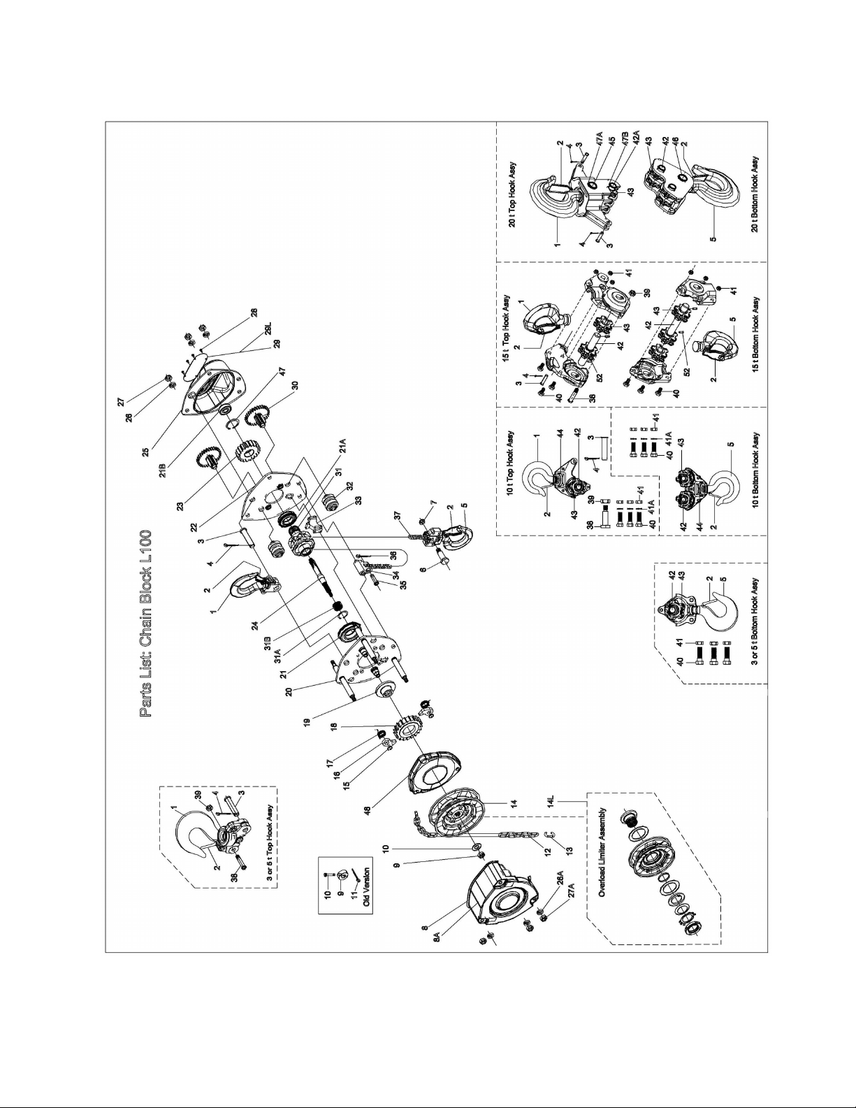
L-100 Chain Hoist Parts Breakdown
34
Page 35

NOTES
35
Page 36

L-100-
Record your purchase and installation information here
Purchased from: Date:
Serial Number: Model Number:
Stock Number:
Location Installed:
Date Installed: Date in Service:
WALTER MEIER (Manufacturing) Inc.
427 New Sanford Road
LaVergne, Tennessee 37086
Phone: 800-274-6848
www.waltermeier.com
36
 Loading...