


This .pdf document is bookmarked
Operating Instructions and Parts Manual
22-inch Woodworking Scroll Saw
Model JWSS-22B
For serial no. 18011801 and higher
JET
427 New Sanford Road Part No. M-727200B
LaVergne, Tennessee 37086 Edition 4 01/2018
Ph.: 800-274-6848 ECR 171108102444
www.jettools.com Copyright © 2018 JET

1.0 IMPORTANT SAFETY
INSTRUCTIONS
WARNING – To reduce risk of injury:
1. Read and understand the entire owner's
manual before attempting assembly or
operation.
2. Read and understand the warnings posted on
the machine and in this manual. Failure to
comply with all of these warnings may cause
serious injury.
3. Replace the warning labels if they become
obscured or removed.
4. This scroll saw is designed and intended for use
by properly trained and experienced personnel
only. If you are not familiar with the proper and
safe operation of a scroll saw, do not use until
proper training and knowledge have been
obtained.
5. Do not use this scroll saw for other than its
intended use. If used for other purposes, JET
disclaims any real or implied warranty and holds
itself harmless from any injury that may result
from that use.
6. Always wear ANSI Z87.1 approved safety
glasses or face shield while using this machine.
(Everyday eyeglasses only have impact
resistant lenses; they are not safety glasses.)
7. Before operating this scroll saw, remove tie,
rings, watches and other jewelry, and roll
sleeves up past the elbows. Do not wear loose
clothing. Confine long hair. Non-slip footwear or
anti-skid floor strips are recommended. Do not
wear gloves.
8. Wear ear protectors (plugs or muffs) if noise
exceeds safe levels.
9. WARNING: Drilling, sawing, sanding or
machining wood products generates wood dust
and other substances known to the State of
California to cause cancer. Avoid inhaling dust
generated from wood products or use a dust
mask or other safeguards to avoid inhaling dust
generated from wood products.
10. Wood products emit chemicals known to the
State of California to cause birth defects or
other reproductive harm. (California Health and
Safety Code Section 25249.6)
11. Do not operate this machine while tired or under
the influence of drugs, alcohol or any
medication.
12. Make certain the switch is in the OFF position
before connecting the machine to the power
supply.
13. Make certain the machine is properly grounded.
14. Make all machine adjustments or maintenance
with the machine unplugged from the power
source.
15. Remove adjusting keys and wrenches. Form a
habit of checking to see that keys and adjusting
wrenches are removed from the machine
before turning it on.
16. Keep safety guards in place at all times when
the machine is in use. If removed for
maintenance purposes, use extreme caution
and replace the guards immediately after
completion of maintenance.
17. Check damaged parts. Before further use of the
machine, a guard or other part that is damaged
should be carefully checked to determine that it
will operate properly and perform its intended
function. Check for alignment of moving parts,
binding of moving parts, breakage of parts,
mounting and any other conditions that may
affect its operation. A guard or other part that is
damaged should be properly repaired or
replaced.
18. Provide for adequate space surrounding work
area and non-glare, overhead lighting.
19. Keep the floor around the machine clean and
free of scrap material, oil and grease.
20. Keep visitors a safe distance from the work
area. Keep children away.
21. Make your workshop child proof with padlocks,
master switches or by removing starter keys.
22. Give your work undivided attention. Looking
around, carrying on a conversation and “horseplay” are careless acts that can result in serious
injury.
23. Maintain a balanced stance at all times so that
you do not fall into the blade or other moving
parts. Do not overreach or use excessive force
to perform any machine operation.
24. Use the right tool at the correct speed and feed
rate. Do not force a tool or attachment to do a
job for which it was not designed. The right tool
will do the job better and more safely.
25. Use recommended accessories; improper
accessories may be hazardous.
26. Maintain tools with care. Keep saw blades
sharp and clean for the best and safest
performance. Follow instructions for lubricating
and changing accessories.
27. Turn off the machine before cleaning. Use a
brush or compressed air to remove chips or
debris — do not use your hands.
2

28. Do not stand on the machine. Serious injury
could occur if the machine tips over.
29. Never leave the machine running unattended.
Turn the power off and do not leave the
machine until it comes to a complete stop.
30. Remove loose items and unnecessary work
pieces from the area before starting the
machine.
31. Keep hands and fingers away from moving saw
blade.
32. Don’t use in dangerous environment. Don’t use
power tools in damp or wet location, or expose
them to rain. Keep work area well lighted.
Additional safety instructions for
scroll saws
33. Scroll saw must be secured to a sturdy
foundation. If there is a tendency for the stand
or workbench to move, it must also be secured
to the floor.
34. Blade must be properly tensioned before
operating. Failure to do so could result in blade
breakage and possible injury.
35. Never start saw with workpiece contacting
blade.
36. Always keep fingers and hands away from
blade. Avoid awkward hand positions where a
sudden slip might cause hand to move into or
toward the blade.
Familiarize yourself with the following safety notices used in this manual:
37. Always hold stock firmly against table. The
provided hold-down should be correctly
positioned over the workpiece.
38. Do not attempt to saw any stock that does not
have a flat surface, without a suitable support.
Do not cut pieces of material too small to hold
by hand.
39. Care must be taken when cutting material with
an irregular cross section. The blade could
pinch before the cut is completed. Any stock,
such as frame molding, must lie flat on the table
surface and not be allowed to rock.
40. Dowels or tubing have a tendency to roll while
being cut and cause the blade to “bite.” Round
material should be held firmly against the table.
41. Turn off saw before backing stock out of an
incomplete cut. Only remove jammed cut-off
pieces after blade has stopped.
42. Make “relief” cuts before cutting long curves.
43. When cutting large or oversize stock, always
make sure material is supported at table height.
44. Do not feed workpiece too fast while cutting.
Feed workpiece only fast enough for the blade
to cut.
45. Never reach under the table while blade is
moving.
machine damage.
injury.
This means that if precautions are not heeded, it may result in minor injury and/or possible
This means that if precautions are not heeded, it may result in serious, or possibly even fatal,
SAVE THESE INSTRUCTIONS
3

1.2 Switch lock-out
To safeguard your machine from unauthorized operation and accidental starting by young children, the use of a
padlock (not included) is highly recommended. See Figure 1. Place the key in a location that is inaccessible to
children and others not qualified to use the tool.
Figure 1
2.0 About this manual
This manual is provided by JET, covering the safe operation and maintenance procedures for a JET Model
JWSS-22B Scroll Saw. This manual contains instructions on installation, safety precautions, general operating
procedures, maintenance instructions and parts breakdown. Your machine has been designed and constructed
to provide consistent, long-term operation if used in accordance with the instructions as set forth in this document.
This manual is not intended to be an exhaustive guide to scroll saw operational methods, choice of blades or
wood stock, etc. Additional knowledge can be obtained from experienced users or trade artic les. Whatever
accepted methods are used, always make personal safety a priority.
If there are questions or comments, please contact your local supplier or JET. JET c an also be reached at our
web site: www.jettools.com.
Retain this manual for future reference. If the machine transfers ownership, the manual should accompany it.
Read and understand the entire contents of this manual before attempting assembly or
operation! Failure to comply may cause serious injury!
Register your product using the mail-in card provided, or register online:
http://www.jettools.com/us/en/service-and-support/product-registration/
4

3.0 Table of contents
Section Page
1.0 IMPORTANT SAFETY INSTRUCTIONS ....................................................................................................... 2
1.2 Switch lock-out ........................................................................................................................................... 4
2.0 About this manual .......................................................................................................................................... 4
3.0 Table of contents ............................................................................................................................................ 5
4.0 Glossary ......................................................................................................................................................... 6
5.0 Specifications ................................................................................................................................................. 7
5.1 Mounting hole pattern ................................................................................................................................. 8
6.0 General features ............................................................................................................................................ 8
7.0 Setup and assembly ....................................................................................................................................... 9
7.1 Shipping contents ....................................................................................................................................... 9
7.2 Tools required for assembly ....................................................................................................................... 9
7.3 Unpacking and cleanup .............................................................................................................................. 9
7.4 Transporting saw ........................................................................................................................................ 9
7.5 Mounting to bench or stand ...................................................................................................................... 10
7.6 Assembling stand (optional) ..................................................................................................................... 10
7.7 Blade storage ........................................................................................................................................... 10
7.8 Foot pedal ................................................................................................................................................ 10
7.9 Dust collection .......................................................................................................................................... 11
8.0 Electrical connections .................................................................................................................................. 11
8.1 GROUNDING INSTRUCTIONS ............................................................................................................... 11
8.2 Extension cords ........................................................................................................................................ 11
9.0 Adjustments ................................................................................................................................................. 12
9.1 Arm tilt ...................................................................................................................................................... 12
9.2 Installing blade ......................................................................................................................................... 12
9.3 Adjusting blade tension ............................................................................................................................ 13
9.4 Material hold-down ................................................................................................................................... 13
9.5 Speed control ........................................................................................................................................... 13
9.6 Squaring blade to table ............................................................................................................................ 13
9.7 Adjusting blade oscillation ........................................................................................................................ 14
9.8 Arm lift retention ....................................................................................................................................... 15
9.9 Blower nozzle ........................................................................................................................................... 15
10.0 Operations .................................................................................................................................................. 15
10.1 General operating tips ............................................................................................................................ 15
10.2 On/off controls ........................................................................................................................................ 15
10.3 Procedure ............................................................................................................................................... 15
11.0 User-maintenance ...................................................................................................................................... 16
11.1 General maintenance ............................................................................................................................. 16
11.2 Lubrication .............................................................................................................................................. 16
11.3 Fuse inspection ...................................................................................................................................... 16
11.4 Commutator brush inspection ................................................................................................................ 17
12.0 Blade selection ........................................................................................................................................... 18
12.1 Width ...................................................................................................................................................... 18
12.2 Pitch ....................................................................................................................................................... 18
12.3 Set .......................................................................................................................................................... 18
12.4 Material ................................................................................................................................................... 18
12.5 Tooth form .............................................................................................................................................. 19
13.0 Optional accessories .................................................................................................................................. 19
14.0 Troubleshooting JWSS-22B Scroll Saw ..................................................................................................... 20
15.0 Replacement Parts ..................................................................................................................................... 21
15.1.1 JWSS-22B Upper & Lower Arm Assembly – Exploded View .............................................................. 22
15.1.2 JWSS-22B Upper & Lower Arm Assembly – Parts List ....................................................................... 23
15.2.1 JWSS-22B Table & Cabinet Assembly – Exploded View .................................................................... 24
15.2.2 JWSS-22B Table & Cabinet Assembly – Parts List ............................................................................ 25
15.3.1 JWSS-22B Drive Link Assembly – Exploded View ............................................................................. 26
15.3.2 JWSS-22B Drive Link Assembly – Parts List ...................................................................................... 26
15.4.1 Stand (OPTIONAL) for JWSS-22B Scroll Saw – Exploded View ........................................................ 28
15.4.2 Stand (OPTIONAL) for JWSS-22B Scroll Saw – Parts List ................................................................. 28
16.0 Electrical Connections – JWSS-22B Scroll Saw ........................................................................................ 29
17.0 Warranty and service ................................................................................................................................. 30
5

4.0 Glossary
Some terms relevant to the scroll saw:
Beam strength: A blade’s resistance to backward
deflection caused by pressure of the workpiece.
Bevel edge cut: Tilt of blade between 0° and 45° to
perform angled cutting operation.
Blade drift: Deviation of blade from a straight line.
The smaller the blade, the more prone to drifting.
Blade tracking: How the blade moves through the
cutting path.
Contour cut: Cutting outside the workpiece line.
Crosscut: A cut made across the grain of a
workpiece.
Deflection: Tendency of blade to be pushed
backward under pressure from the workpiece.
Feed rate: Linear travel of workpiece into blade.
Freehand: Moving the workpiece into the blade
using only the hands, without a fixed positioning
device.
Fret work: Cutting inside the workpiece; also called
open work, or pierce cutting.
Kerf: The resulting cut or gap made by the blade.
Kickback, or Lift: The tendency of workpiece to
rise off the table due to being caught by the blade.
Leading edge: Edge of workpiece that first gets
pushed into blade.
Parallel: Position of saw arm equal in distance at
every point to the table surface.
Parallel link: style of scroll saw in which a motor
pushes rods in upper and lower arms that move
articulated arms holding the blade. (The JET scroll
saw is this type.)
Perpendicular: 90° (right angle) intersection or
position of vertical and horizontal planes, such as
saw blade to table.
Pin-end blade: Blade that requires a pin to secure
it to the saw. (These are not suitable for intricate
fretwork.)
Plain-end blade: Blade that slides into a clamp
without need of a pin holder. These are preferred for
delicate fretwork. (The JET scroll saw uses this
type.)
Rake angle: Angle of a blade tooth in respect to a
line perpendicular to the back edge of blade.
Relief cut: Extra cut to remove waste material and
prevent the blade from binding when cutting a curve.
Rip Cut: A cut made along the grain of the
workpiece.
Scroller: User of a scroll saw. Sometimes called
“scroll-sawyer”.
Scroll work: General term for designs with spirals
and rolling curves.
Stack cutting: Placing multiple workpieces
together for simultaneous cutting. (CAUTION:
Pieces must be properly taped or glued together to
prevent sliding.)
Throat capacity: Distance from blade to body
column; identifies maximum workpiece size.
Trailing edge: Edge of workpiece that last contacts
blade.
6

5.0 Specifications
Model number ................................................................................................................................................ JWSS-22B
Stock numbers:
Scroll saw with foot switch ............................................................................................................................727200B
Scroll saw with foot switch and stand ...........................................................................................................727200K
Optional stand only .......................................................................................................................................727200S
Motor and electricals:
Motor type ................................................................................................................................................ brushed DC
Horsepower ........................................................................................................................................ 1/16 HP (50W)
Phase ............................................................................................................................................................... single
Voltage ............................................................................................................................................................. 120 V
Cycle .................................................................................................................................................................. 60Hz
Listed FLA (full load amps) ................................................................................................................................ 1.3 A
Starting amps........................................................................................................................................................ 2 A
Running amps (no load) .................................................................................................................................... 0.5 A
On/off switch .................................................................................................................... rocker style, and foot pedal
Power cord............................................................................................................................. 18 AWG, 6 ft. (183 cm)
Power plug installed (saw and foot pedal) ...................................................................................................... 15 amp
Foot pedal cord length ....................................................................................................................................... 7.2 ft.
Recommended circuit and fuse/breaker size
Overload fuse ......................................................................................................................................... 3.15A, 250V
Blade and capacities:
Stroke .............................................................................................................................................. 3/4 in. (18.6 mm)
Speed ..................................................................................................................... variable, 400 to 1550 stroke/min.
Throat capacity ............................................................................................................................................ 22-3/8 in.
Blade type used ..................................................................................................................... plain-end (pinless) 5 in.
Blades included ...................................................................................................................................... (5) Skip type
Maximum cutting depth .......................................................................................................................... 2 in. (51 mm)
Arm tilt .................................................................................................................... 45 degrees left; 45 degrees right
Main materials:
Body and tool tray ............................................................................................................................................... steel
Main table ......................................................................................................................................... ground cast iron
Trunnion ............................................................................................................................................................. steel
Arm ............................................................................................................................................... steel, plastic cover
Table:
Table dimensions (LxW) ........................................................................................ 23.62 x 12.67 in. (600 x 322 mm)
Table slot width .................................................................................................................................................. 5 mm
Table height from floor, on optional stand ............................................................................... adj ustable; 32 to 38 in.
Distance front edge of table to blade (approximate) ........................................................................ 3-5/8 in. (92 mm)
Dimensions:
Optional stand footprint (LxW) ................................................................................... 28 x 25-1/2 in. (711 x 648 mm)
Overall dimensions – saw only (LxWxH) ............................................ 33 x 15-1/2 x 17-1/2 in. (838 x 394 x 445 mm)
Overall dimensions – saw on stand (LxWxH) ......................................... 33 x 25-1/2 x 48 in. (838 x 648 x 1219 mm)
Shipping dimensions – saw only .................................................. 35.4" x 17.7" x 18.9" (900mm x 450mm x 480mm)
Dust collection:
Dust port outside diameter ................................................................................................................................ 1-1/2”
Recommended dust extraction volume ........................................................................ 300–350 CFM (8.5–10 CMM)
Weights:
Net weight, saw only .......................................................................................................................... 68.2 lbs (31 kg)
Net weight, optional stand only ......................................................................................................... 21.5 lbs (9.8 kg)
1
subject to local/national electrical codes.
L = length; W = width; H = height
Specifications in this manual were current at time of publicati on, but b eca use of our policy of continuo us im pro vem ent ,
JET reserves the right to change specifications at any time and without prior notice, without incurring obligations.
1
...................................................................................................... 15A
7

5.1 Mounting hole pattern
Figure 2: scroll saw mounting hole pattern
6.0 General features
Figure 3: JWSS-22B features
8

7.0 Setup and assembly
Read and understand all
assembly instructions before attempting
assembly. Saw must remain unplugged from
power source during assembly procedures.
7.1 Shipping contents
Refer to Figure 4.
1 Scroll saw (not shown)
4 Leveling feet with hex nuts
2 Lower blade holders
1 Foot pedal assembly
1 Dust port
1 Blade rack
5 Blades, skip type (not shown)
4 Rubber washer – (HP5)
1 Operator’s manual (not shown)
1 Product registration card (not shown)
#2 Cross-point screwdriver (for blade rack)
Figure 5: hardware package JWSS22B-SHP
7.3 Unpacking and cleanup
1. Remove all contents from shipping carton.
Remove protective coating from the table using
a soft cloth moistened with a solvent. (Do not
use acetone, gasoline or lacquer thinner for this
purpose, as these will damage painted and
plastic parts.)
2. Inspect contents for shipping damage or
missing parts. Report any damage or part
shortages to your distributor. (Note: Check saw
for any pre-installed parts before reporting part
shortage.)
Figure 4: contents (not to scale)
Stand (Optional Accessory)
Refer to Figure 10, or sect. 15.4.1.
2 Long top braces – (#3)
2 Short top braces – (#4)
2 Short bottom braces – (#7)
2 Long bottom braces – (#8)
4 Legs – (#5)
4 Leg extensions – (#10)
1 Hardware package (see Figure 5); contains:
4 Hex cap screws 5/16x1 – (HP1)
24 Carriage bolts 5/16x1/2 – (HP2)
32 Flat washers 5/16 – (HP3)
28 Hex nuts 5/16 – (HP4)
7.4 Transporting saw
Do NOT lift scroll saw beneath
arm (Figure 6) which may result in damage to
linkage system. Always lift using motor and
edge of table (Figure 7).
Figure 6: INCORRECT lifting
7.2 Tools required for assembly
14mm open-end wrench (for foot pads)
12mm wrench (for optional stand only)
3mm hex wrench (for blade guide)
Figure 7: correct lifting
9

7.5 Mounting to bench or stand
The scroll saw should be
installed upon a sturdy, flat surface with all four
legs contacting the surface. Do NOT install with
saw partially hanging over edge of table or
workbench.
If scroll saw will not be bolted down to a surface,
install the four foot pads to reduce vibration. See
Figure 8. Lower hex nut may be adjusted for height.
Tighten top hex nut down against saw foot.
Figure 8: leveling foot
The preferred method is to mount the saw directly to
a solid workbench or table, or to the optional JET
stand. If mounting to a workbench, use a pad
(provided rubber washers) between saw and bench
to minimize vibration. See Figure 9.
3. If stand will not be bolted to the floor, install the
leveling feet (shown in Figure 8) that were
included with the scroll saw, onto the bottoms of
the stand leg extensions (Figure 10).
4. Position stand upright on level floor. Push down
on stand assembly to settle it on floor, then fully
tighten all fasteners with 12mm wrench.
5. Some scrollers prefer to tilt the saw toward them
for convenience. If this is desired, adjust only
the two front leg extensions.
6. Mount scroll saw to stand, using fasteners
shown (also identified in Figure 5).
Figure 10: stand assembly (optional accessory)
Figure 9: bench mounting (fasteners not included)
If a non-permanent method is preferred, an
alternative is to fasten the saw to a thick plywood
board (minimum 3/4-inch), then attach the board to
a table using clamps.
7.6 Assembling stand (optional)
1. Assemble stand pieces, referring to Figure 10.
(Refer to exploded view, sect. 15.4.1, if further
clarification is needed.) Only hand-tighten all
fasteners at this time.
NOTE: One end of each leg (#5) forms a slight
“V” shape – this end goes at the top. The bottom
edge of the leg forms a straight line.
2. The leg extensions (#10, Figure 10) can be
adjusted for height.
7.7 Blade storage
The blade rack (Figure 11) can be mounted to either
side of the scroll saw. It contains holes for storage
of blades inside “test tubes” (not provided).
Additionally, four slots provide storage for blades
pre-inserted into a blade holder.
Figure 11: blade storage
7.8 Foot pedal
Connect plug from scroll saw into receptacle on
back of foot pedal. Then plug foot pedal into power
source. (If not using foot pedal, plug saw directly into
power source; the on/off switch is then pressed to
start and stop the saw.)
10

It is strongly recommended the foot pedal be
secured in place using screws through the two
holes. It may be secured directly to the floor or a
wide board laid beneath the saw.
7.9 Dust collection
Slide dust port into the slot on underside of table. A
dust collector or shop vacuum can be connected to
the dust port with a hose and reducing adaptor (not
provided).
8.0 Electrical connections
The JWSS-22B Scroll Saw is prewired for 120-volt
power. The saw comes with a plug designed for use
on a circuit with a grounded outlet that looks like the
one pictured in A, Figure 12.
Before connecting to power source, be sure switch
is in off position.
It is recommended that the scroll saw be connected
to a dedicated 15 amp circuit with circuit breaker or
fuse. If connected to a circuit protected by fuses, use
time delay fuse marked “D”. Local codes take
precedence over recommendations.
This tool is for use on a nominal 120-V circuit, and
has a grounded plug that looks like the plug
illustrated in sketch A in Figure 12. A temporary
adaptor that looks like the adaptor illustrated in
sketches B and C may be used to connect this plug
to a 2-pole receptacle as shown in sketch B if a
properly grounded outlet is not available. The
temporary adaptor should be used only until a
properly grounded outlet (sketch A) can be installed
by a qualified electrician. The green colored rigid
ear, lug, or the like extending from the adaptor must
be connected to a permanent ground such as a
properly grounded outlet box cover. Whenever the
adaptor is used, it must be held in place by a metal
screw.
In Canada, the use of a temporary adaptor is not
permitted by the Canadian Electrical Code, C22.1.
8.1 GROUNDING INSTRUCTIONS
This machine must be grounded. In the event of a
malfunction or breakdown, grounding provides a
path of least resistance for electric current to reduce
the risk of electric shock. This tool is equipped with
an electric cord having an equipment-grounding
conductor and a grounding plug. The plug must be
plugged into a matching outlet that is properly
installed and grounded in accordance with all local
codes and ordinances.
Do not modify the plug provided - if it will not fit the
outlet, have the proper outlet installed by a qualified
electrician.
Improper connection of the equipment-grounding
conductor can result in a risk of electric shock. The
conductor with insulation having an outer surface
that is green with or without yellow stripes is the
equipment-grounding conductor. If repair or
replacement of the electric cord or plug is
necessary, do not connect the equipment-grounding
conductor to a live terminal.
Check with a qualified
electrician or service personnel if the grounding
instructions are not completely understood, or if
in doubt as to whether the tool is properly
grounded. Failure to comply may cause ser ious
or fatal injury.
Use only 3-wire extension cords that have 3-prong
grounding plugs and 3-pole receptacles that accept
the tool's plug.
Repair or replace damaged or worn cord
immediately.
Figure 12: plug configuration
8.2 Extension cords
The use of extension cords is discouraged; try to
position machines near the power source. If an
extension cord is necessary, make sure it is in good
condition. When using an extension cord, be sure to
use one heavy enough to carry the current your
product will draw. An undersized cord will cause a
drop in line voltage resulting in loss of power and
overheating. Table 1 shows correct size to use
depending on cord length and nameplate ampere
rating. If in doubt, use the next heavier gauge. The
smaller the gauge number, the heavier the cord.
Ampere
Rating
More
Than
0 6 18 16 16 14
6 10 18 16 14 12
10 12 16 16 14 12
12 16 14 12
Not
More
Than
Volts
120 25 50 100 150
AWG
Extension Cord Recommendations
Total length of
cord in feet
Not
Recommended
Table 1
11
9.0 Adjustments
Before making adjustments to
saw, push rocker switch to OFF. Also unplug
saw from power if working ar ound blade area.
9.1 Arm tilt
The table remains stationary, so the operator’s
hands can remain in the same comfortable position,
with no risk of the workpiece sliding off the table.
The arm can be tilted up to 45-degrees left or right
for beveled cuts, which are frequently used in
projects such as marquetry.
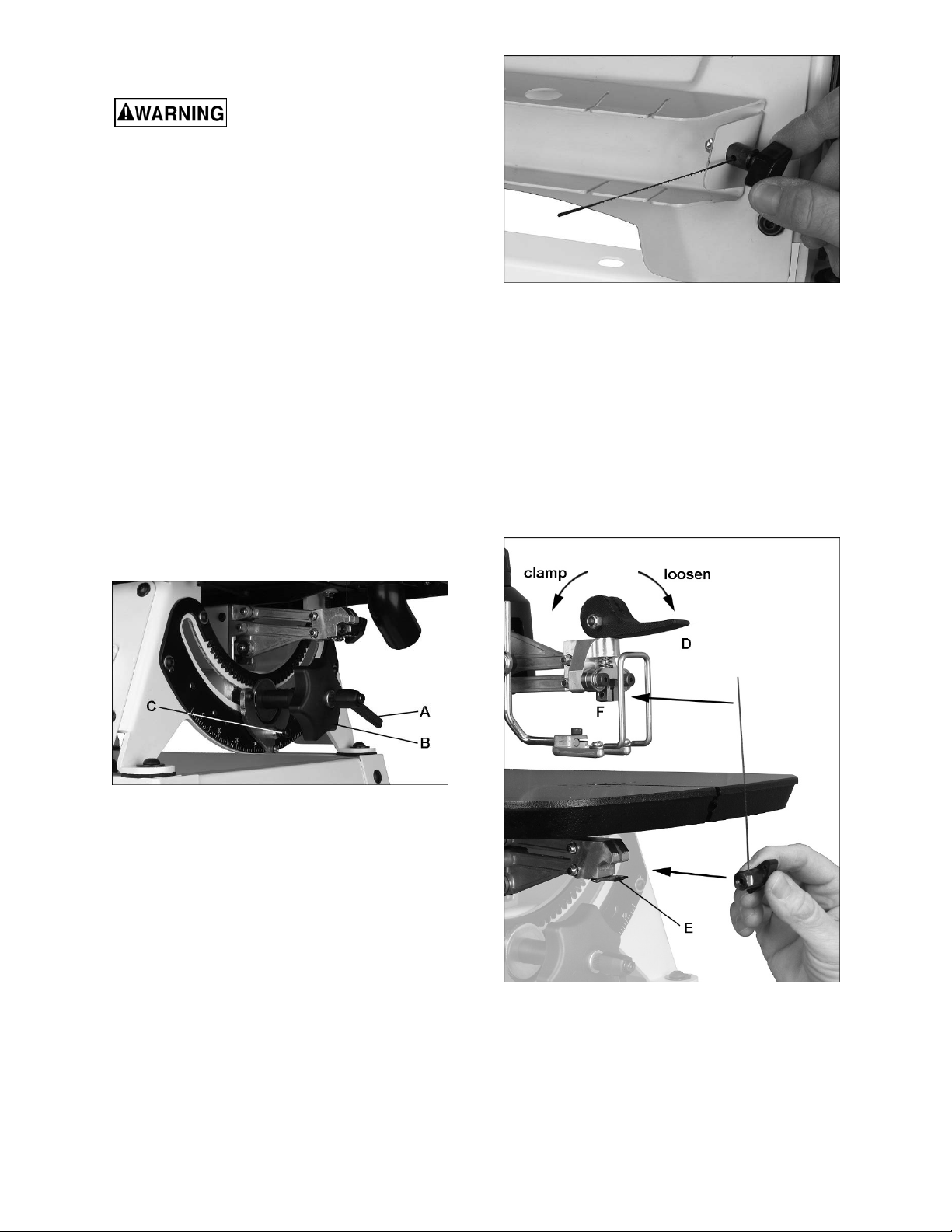
Refer to Figure 13.
1. Loosen lock handle (A).
2. Make sure upper guard and blower nozzle
positions will not conflict with table.
3. Rotate handle (B) to desired angle. Preset
stops are available at 90°, 45°, 30° and 22.5°,
left and right. Push detent pin (C) while rotating
handle (B) until pin engages hole.
4. Tighten lock handle (A) and release pin.
Lock handle (A) is adjustable to prevent obstruction
when in angled position: Pull out handle and rotate
on pin, then release, making sure it reseats on pin.
Figure 14: installing blade into holder
4. Flip clamping lever (D, Figure 15) toward front
of saw to release guide.
5. Push blade holder into clip (E) while guiding
blade through table slot.
6. Push top end of blade into upper guide (F),
making sure it rests between the contact points
of guide set screws, and against the back stop.
7. Flip clamping lever (D) toward rear of saw to
tension blade. Do not over-tension blade; this
can result in blade breakage or premature wear
to clamping surfaces.
Figure 13: arm tilt adjustment
9.2 Installing blade
1. Turn off saw.
2. Insert lower blade holder (Figure 14) into hole
in blade rack for leverage, and loosen knob.
3. Slide blade into holder deep enough to gain
sufficient clamping, but not all the way which
can result in blade being too short for sufficient
gripping by upper guide. Make sure blade teeth
point down, toward the blade holder. Tighten
blade holder knob.
NOTE: If the blade holder set screw is backed
out, turn it in with a 3mm hex wrench until it
touches the tip of the knob when knob is
tightened down. You may need to stabilize the
blade holder with a 10mm wrench on the flats
while doing this.
Figure 15: installing blade into guides
8. Check that blade teeth point forward and down
toward table.
9. Try moving blade by hand to make sure it is
secure. Pluck the blade with your finger, as you
would a guitar string – it should emit a clear note
if properly tensioned.
12
TIP: If changing a blade while cutting fretwork, you
may first push blade through pilot hole in workpiece,
then install blade to saw. See Figure 16. This
prevents having to raise the arm for the first cut.
Figure 16: installing blade with workpiece
9.3 Adjusting blade tension
If blade refuses to be clamped tightly according to
the above steps, one or both of the following
adjustments may be needed (Figure 17):
• Upper clamp spring pressure can be adjusted
by lifting handle (D) to vertical position. Rotate
handle clockwise one turn to increase pressure,
then push handle into clamping position. Note:
Too much handle rotation will prevent clamping.
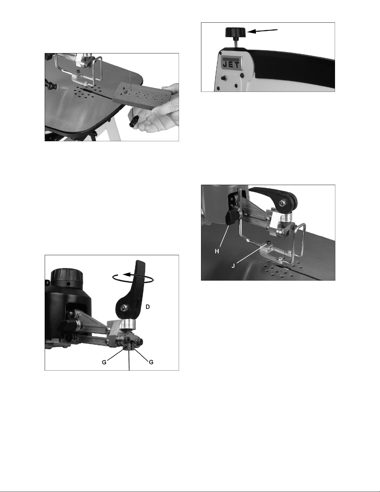
Figure 18: arm adjustment knob
9.4 Material hold-down
Refer to Figure 19.
Adjust material hold-down as close to workpiece as
possible without impeding workpiece movement.
For vertical adjustment, Loosen knob (H, Figure 19)
and slide hold-down to position. Tighten knob.
For forward/back movement and angling to table,
loosen socket head screw (J) and adjust. Tighten
screw.
• Turn set screws (G) with 3mm hex wrench
clockwise to reduce gap between clamping
surfaces.
Figure 17: tension adjustment
Either of the above steps should resolve blade
tension problems. If problem still exists:
• Rotate arm adjustment knob (Figure 18)
clockwise by hand. This will raise arm and apply
more tension to blade.
IMPORTANT: Rotating arm adjustment knob
for tension purposes should only be done if
absolutely needed, as it will affect later blade
oscillation settings (sect. 9.7).
Figure 19: hold-down
9.5 Speed control
Refer to Figure 3.
Rotate speed control knob while saw is running –
clockwise to increase blade strokes per minute,
counterclockwise to decrease.
9.6 Squaring blade to table
Refer to Figures 20 and 21.
The blade may get out of alignment with the table
over time, depending upon how often the saw is
used, and frequent use of the tilt mechanism.
Periodically check squareness of blade to table as
follows.
1. Turn off saw, unplug from power source.
2. Make sure blade is fully tensioned.
3. Set blade tilt to “0” (90 degrees).
13

4. Place a machinists square or other 90-degree
measuring device on table and against blade
(Figure 20). Do not deflect blade by pushing into
it.
Figure 20: inspecting blade squareness
5. If side of blade does not lie flush against square,
first check that the set screws (see G, Figure
17) protrude evenly into the clamping area.
Adjust if needed.
6. If blade is still not perpendicular, loosen eight
screws on trunnion plates, at front and back of
saw (Figure 21)
7. Nudge trunnion/arm assembly until side of
blade is flush to square.
8. Tighten all screws at front and back.
9. If needed, loosen screw on pointer (K) and
adjust it to zero. Tighten screw.
This adjustment is based upon user’s preference; as
the scroller gains experience, he/she will get a feel
for the oscillation that is most efficient for the work
at hand.
1. Turn off saw and remove blade.
2. First verify that upper arm is parallel to table
surface (Figure 22). Push arm down, and
measure at front and back of arm; if
measurements are different, rotate arm
adjustment knob (L) until upper arm is parallel.
Figure 22: arm/table parallelism
3. Adjustments to blade oscillation can be subtle;
place a square or block of wood on table and
alongside blade as reference.
4. Loosen screws on moto r flange (M, Figure 23)
with 4mm hex wrench. Only loosen screws
enough to allow motor rotation.
5. Turn motor shaft (N, Figure 23) with flat-blade
screwdriver to observe blade motion.
Alternatively, you may turn on saw to slowest
speed to observe blade motion.
Figure 21: squaring blade to table
9.7 Adjusting blade oscillation
Refer to Figure 22.
Blade movement can be adjusted to accommodate
different wood stock and types of operations. For
example, for faster, more aggressive cutting the
blade can be adjusted for slight backward
movement on the upstroke, and slight forward
movement into the wood on the downstroke. For
slower, fine detail work and more control,
completely vertical blade movement is often
preferred.
14
Figure 23: blade oscillation

6. Slowly rotate entire motor by hand to adjust
oscillation. Clockwise rotation will make blade
movement more aggressive on downstroke.
Counterclockwise will make blade more
aggressive on upstroke. See Figure 23.
TIP: If more rotation is needed, turn off saw and
install motor mount screws in second set of
holes behind motor flange.
7. When desired oscillation is achieved, securely
tighten motor mount screws (M).
9.8 Arm lift retention
Refer to Figure 24.
If arm will not remain in position after being raised,
loosen hex nut (14mm wrench) and slightly turn
adjustment screw clockwise with flat blade
screwdriver, until arm remains in raised position. Do
not overtighten. Tighten hex nut.
7. Make relief cuts as needed to prevent binding
of blade in workpiece.
8. A blade has a tendency to follow the wood
grain. Be prepared to compensate for this to
achieve accurate cuts.
9. Use caution when sawing round pieces, such
as dowels, which tend to roll while cutting.
10. Keep fingers away from cutting path. Avoid
awkward hand positions or getting fingers
wedged between saw arm and workpiece when
cutting small workpieces.
11. For fretwork, drill all needed pilot holes at the
same time before moving to the scroll saw. Drill
pilot holes as close as possible to reference
lines.
12. As a general rule, select the narrowest blades
recommended for intricate curve cutting, and
widest blades for straight cuts or large curve
cuts.
13. Run saw only at high enough speed to
efficiently do the work. Constant running at
maximum speed is not necessary for most
operations, may reduce control of the cutting
process, and may hasten wear on the saw.
Figure 24: tightening arm lift
9.9 Blower nozzle
Adjust blower nozzle away from operator, and as
close to blade as needed without interfering with
blade or workpiece movement.
10.0 Operations
10.1 General operating tips
1. Always use a clean, sharp blade.
2. Maintain proper posture to avoid strain. Saw
table should be set approximately level with
operator’s elbows.
3. Avoid wrist or finger strain which can occur by
constantly pushing workpiece against table.
Always use hold-down whenever possible.
4. Guide the wood into the blade slowly to prevent
blade breakage.
5. You will achieve best results when cutting wood
less than 1-inch thick. When cutting stock
thicker than 1-inch, guide the stock very slowly
into the blade, taking care not to bend or twist
the blade.
6. Blade should have minimum 3 teeth in contact
with workpiece at all times.
10.2 On/off controls
With foot pedal: Push on/off switch to ON position
(I). Press foot pedal to operate saw, release pedal
to stop.
Without foot pedal: Push on/off switch to ON
position (I); saw will operate. Press switch to OFF
position (O) to stop.
If foot pedal is not used and
power outage occurs during operation, blade
will resume motion when power is restored.
Turn off switch immediately after pow er outage
to avoid accidental restart.
10.3 Procedure
1. Install blade appropriate for desired operation.
Make sure blade is properly tensioned, and
teeth point forward and down toward table.
2. Position blower nozzle and hold-down.
For straight cutting or outside curve cutting:
3. Turn on saw and allow blade to reach full
operating speed.
4. Set speed using variable control knob.
5. Hold workpiece firmly against table and feed
workpiece directly into front edge of blade with
steady pressure. See Figures 25 and 26. Do not
use excessive pressure – allow the blade to do
the work. Compensate for blade drift.
15
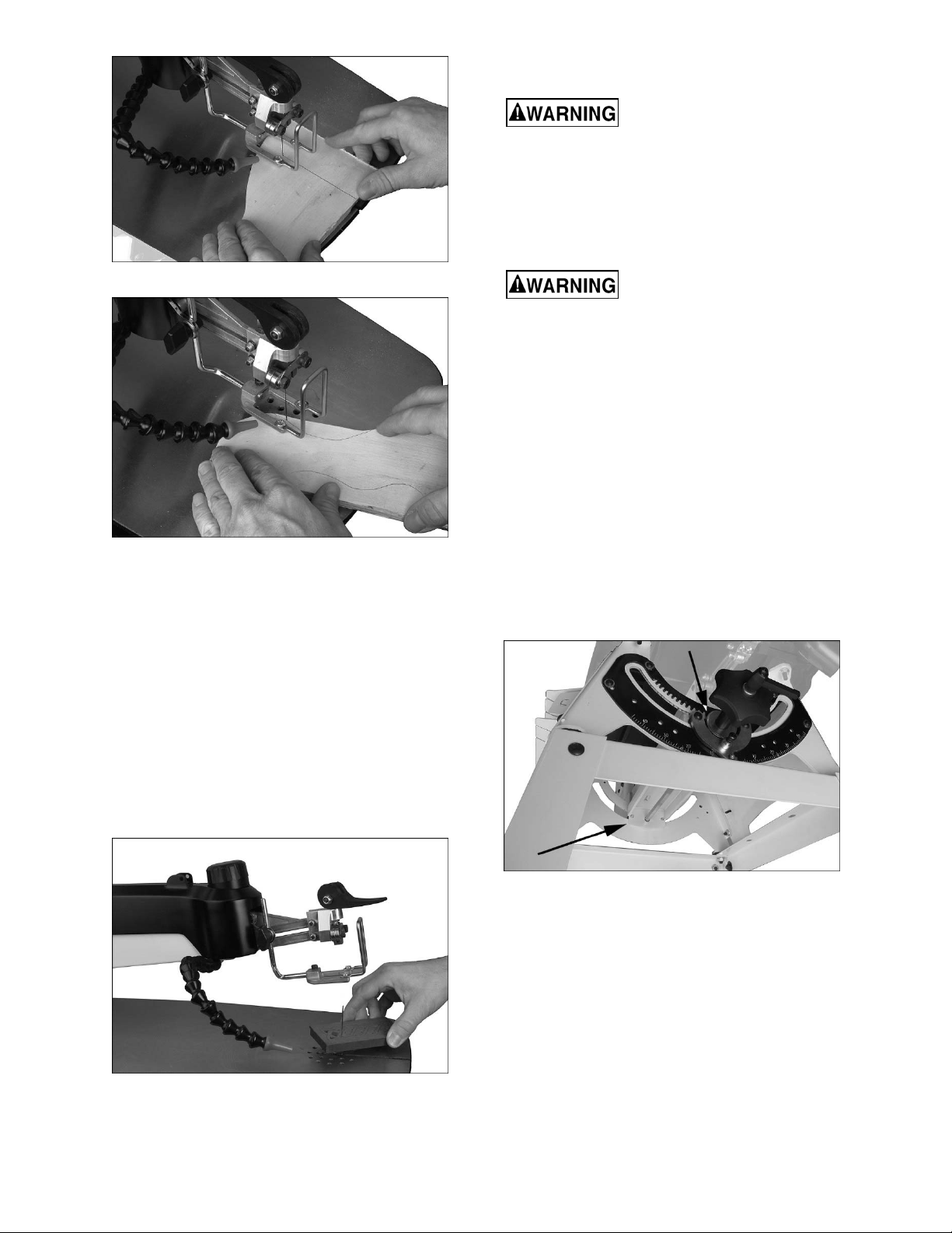
Figure 25: straight cutting
Figure 26: outside curve cutting
For fretwork (inside cutting):
1. Drill pilot holes in workpiece just large enough
for blade insertion.
2. Release clamp lever (D, Figure 27) and raise
arm.
3. Guide blade through pilot hole in workpiece.
11.0 User-maintenance
Always unplug scroll saw from
power before performing maintenance. Failure
to comply may result in serious personal injury.
11.1 General maintenance
Clean wood dust from the saw frequently, using a
vacuum or compressed air, or damp cloth. Use a
soft bristle brush for crevices.
Use proper eye and respiratory
protection if using compressed air.
Keep the table clean. Periodically apply a light coat
of paste wax or spray protectant to the table to
prevent rust and maintain a smooth surface.
When finished cutting, release blade from upper
clamp to remove unneeded tension on clamp
spring. Remove blade if saw will be stored for longer
periods.
Periodically inspect the prongs of the lower spring
plate (see E, Figure 15). Bend upward slightly if
needed to ensure a firm grip upon lower blade
holder.
11.2 Lubrication
Periodically apply light dabs of grease to front and
rear trunnions (Figure 28) where parts slide against
one another.
4. Lower arm and tighten clamp lever (D).
5. Hold workpiece tightly against table and turn on
saw. Set speed using variable control knob.
6. Smoothly guide workpiece into blade, using
light pressure. Avoid coming to a complete stop
while cutting.
Figure 27: fretwork cutting
Figure 28
Bearings in the drive mechanism are pre-lubricated
and sealed; no further attention is needed for these.
11.3 Fuse inspection
The scroll saw is equipped with a 5-amp fuse for
overload protection. If the saw stops working,
inspect fuse:
1. Unscrew fuse cap (Figure 29) and pull fuse out
of cap.
2. If fuse has blown, replace it.
3. Install new fuse into cap, then screw cap into
hole.
16
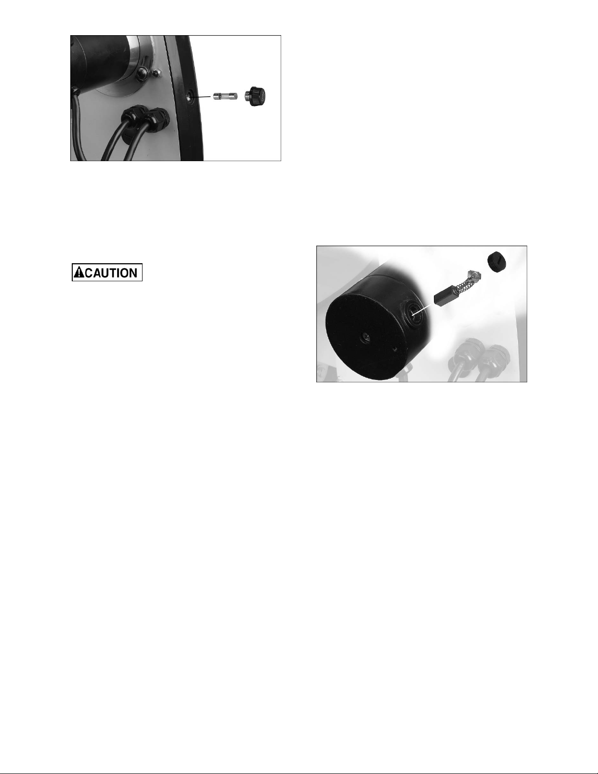
Figure 29
11.4 Commutator brush inspection
To maintain motor efficiency, inspect the two carbon
brushes every two months, or more frequently if saw
is heavily used. Stalling or loss of power may be a
symptom of worn carbon brushes. If one brush is
worn out, replace both at the same time.
Continued use of a damaged or
worn brush may result in damage to motor
armature.
1. Unplug saw from power source.
2. Unscrew and remove cap with flat blade
screwdriver. See Figure 30.
3. Gently pry up an edge of the brass clip, until the
spring causes it to disengage from hole. (Notice
orientation of brush as you remove it; it should
be inserted in the same manner; curvature of
brush will match curvature of motor.)
4. Pull out brush and inspect. Brush should be
replaced if any of the following are discovered:
• Brush has worn to about 1/2-inch long.
• Signs of crumbling, burning or breaking.
• End of brush is rough or pitted.
• Abnormal coloration of spring
• Broken lead in spring
• Collapsed spring
5. Install new brush (or reinstall current brush) and
gently press it all the way into hole until the
brass clip is secured.
6. Install cap.
7. Repeat for other brush.
NOTE: It is recommended that saw be run without
load for several minutes to seat new brushes.
Figure 30
17

12.0 Blade selection
Refer to Figures 31 and 32.
The following information is general in nature. The
scroller is encouraged to research specific options
to meet project needs. Note that the same
specifications may vary among manufacturers.
A wide array of blades are available for the scroll
saw. Woodworking blade sizes range from #3/0 to
#12.
Here are factors to consider when selecting a blade:
• Type of material to be cut (hardwood,
softwood?).
• Thickness of workpiece (thicker pieces will
require larger blades).
• Features of workpiece (straight cuts, sweeping
curves or tight fretwork?).
These factors are important because they involve
basic concepts of blade design. There are 5 blade
features that normally vary to meet certain kinds of
sawing requirements. They are:
1. width
2. pitch (number of teeth per inch)
3. tooth set
4. blade material
5. tooth form
12.1 Width
Width is measured from back edge of blade to tip of
tooth. Generally, wider blades are used for making
straight cuts and long curves. Narrow blades are
suited for cuts with tight corners, such as fretwork.
When cutting straight lines with a narrow blade, the
blade may have a tendency to drift (called “blade
lead”).
12.2 Pitch
Pitch is measured in “teeth per inch” (TPI) and can
be constant or variable.
A fine pitch (more teeth per inch) will cut slowly but
more smoothly, and minimize vibration. A coarse
pitch (fewer teeth per inch) will cut faster but more
roughly.
Try to use a blade that will have a minimum of 3
teeth engaged in the workpiece at any given time.
12.3 Set
“Set” refers to the manner in which the blade teeth
are bent or positioned. Bending the teeth creates a
kerf that is wider than the back of the blade. This
helps the operator more easily pivot a workpiece
through curve cuts, and decreases friction between
blade and workpiece on straight cuts. Two common
sets are the straight (or alternating) and the raker.
Figure 31: blade anatomy
12.4 Material
Blades are manufactured by stamping, milling, or
grinding.
• Stamped blades are punched out on a press
from sheet steel. The teeth are given an
alternate set to allow clearance in the kerf.
• Milled blades are made by flattening a steel
wire, cutting the teeth through a “milling”
process, then heat-hardening the steel.
• Ground blades have high-carbon steel teeth
which tend to hold their sharpness longer, and
provide smooth cuts.
Special styles are also available, such as twist and
spiral blades, which cut from all sides.
Most blades offered are 5 inches long; if a longer
blade is acquired the end can be snipped off to
accommodate the saw.
Optimally, a blade (and the operator’s technique)
should leave smooth, clean cuts that do not require
sanding, as it is often very difficult to sand inside
cuts after they are made.
Instead of purchasing a wide assortment of styles
from the start, the scroller may find a few carefullyselected styles will serve most of his or her needs.
The selection can be expanded as the scroller gains
experience.
18

12.5 Tooth form
Figure 32 shows common blade forms. Tooth f orm
has an effect on cutting rate.
Regular: Standard blade form with evenly spaced
teeth and zero-degree rake angle. Offers clean cuts
at slower feed rates.
Skip Tooth: More space between teeth, for good
chip removal and fast cuts.
Double Tooth: A skip tooth with larger gaps
between tooth sets; good chip removal, fast cutting.
Reverse Tooth: Prevents underside tear-out,
leaves clean edge.
Spiral: Cuts on all sides without turning workpiece;
limited applications but good for looser fretwork.
Crown Tooth: Cuts on both up and down strokes
for clean, splinter-free edges. Depending on blade
oscillation settings, a crown tooth blade may often
be turned over for a fresh set of cutting teeth.
Figure 32: blade forms
13.0 Optional accessories
These accessory items, purchased separately, can enhance the functionality of your scroll saw. Contact your
dealer to order, or call JET at the phone number on the cover.
727200S – Steel stand for JWSS-22B 727201 – Lower Blade Holder (set of 3)
19

14.0 Troubleshooting JWSS-22B Scroll Saw
Symptom Possible Cause Correction *
Motor will not start. Low voltage. Check power line for proper voltage.
Motor will not start:
fuses blow or circuit
breaker trips.
Machine slows when
operating.
Tilting mechanism
difficult to move.
Blades frequently
break.
Blade refuses to
tension properly, or
keeps slipping.
Open circuit in motor or loose
connection.
Damaged cord or plug. Inspect and replace.
Carbon brushes worn. Replace brushes.
Short circuit in line cord or plug. Inspect cord or plug for damaged
Short circuit in motor or loose
connections.
Incorrect fuses or circuit breakers in
power line.
Applying too much pressure to
workpiece.
Caked dust or other obstruction in
trunnion assemblies.
Incorrect blade tension. Set proper tension.
Blade being overworked. Reduce feed rate.
Wrong blade for job. Select proper blade.
Blade twisting in workpiece. Avoid side pressure on blade. Reduce
Too few teeth per inch. Blade should have minimum 3 teeth in
Blade not seated properly. Inspect entry of blade into upper and lower
Clamping lever needs tightening. Tighten clamp lever.
Inspect all lead connections on motor for
loose or open connections.
insulation and shorted wires.
Inspect all connections on motor for loose
or shorted terminals or worn insulation.
Install correct fuses or circuit breakers.
Feed workpiece more slowly.
Clean trunnion areas and apply light dabs
of grease to contacting parts.
feed rate.
contact with workpiece.
blade chucks.
Set screws in upper blade chuck are
backed out, not contacting blade.
Blade clamp has oil or debris on it. Clean blade clamp, ends of set screws.
Blade drift. Some drift is unavoidable depending
upon size of blade and type of cut.
Incorrect blade tension. Increase tension.
Excessive vibration. Saw improperly mounted. Secure saw properly to bench or stand.
Unsuitable mounting surface. Less vibration will occur with a heavier
Arms/linkage system not tight. Tighten trunnion lock knob.
Loose motor mounting. Tighten motor mount screws.
* WARNING: Some corrections may require a qualified electrician or service personnel.
Table 2
Tighten set screws.
Compensate by manipulation of workpiece
into blade.
work bench. Use pads or fiber washers at
mounting contact points.
20

15.0 Replacement Parts
Replacement parts are listed on the following pages. To order parts or reach our service department, call 1-800274-6848 Monday through Friday, 8:00 a.m. to 5:00 p.m. CST. Having the Model Number and Serial Number of
your machine available when you call will allow us to serve you quickly and accurately.
Some parts are shown for reference only and may not be available individually.
Non-proprietary parts, such as fasteners, are usually available at local hardware stores or may be ordered from
JET.
21

15.1.1 JWSS-22B Upper & Lower Arm Assembly – Exploded View
17
18
5
6
1
8
13
12
4
48
16
14
3
15
49
2
9
10
11
48
46
19
52
8
47
7
21
20
8
45
1
24
24
32
8
31
26
23
14
22
30
34
36
35
51
50
37
33
38
39
29
40
28
41
45
27
14
25
43
53
44
42
22

15.1.2 JWSS-22B Upper & Lower Arm Assembly – Parts List
Index No Part No Description Size Qty
1 ................ F009668 .................... Button Head Socket Screw ...................................... #10-32x1/4 .................... 2
2 ................ JWSS22B-202 ........... Top Cover ................................................................ ...................................... 1
3 ................ JWSS22B-203 ........... Switch Rubber Cover ............................................... ...................................... 1
4 ................ JWSS22B-204 ........... Switch ...................................................................... ...................................... 1
5 ................ TS-1521031 .............. Socket Set Screw .................................................... M4x8 ....... ...................... 1
6 ................ JWSS22B-206 ........... VR Knob with Speed Label ...................................... ...................................... 1
7 ................ JWSS22B-207 ........... Upper Arm ............................................................... ...................................... 1
8 ................ F009916 .................... Button Head Socket Screw ...................................... #10-32x5/16 .................. 7
9 ................ F009670 .................... Button Head Socket Screw ...................................... #10-32x3/8 .................... 2
10 .............. JWSS22B-210 ........... Dust Blower ............................................................. ...................................... 1
11 .............. TS-081B022 .............. Pan Head Screw ...................................................... #8-32x3/8 ...................... 2
12 .............. JWSS22B-212 ........... Hold Down Mount Plate ........................................... ...................................... 1
13 .............. JWSS22B-213 ........... Hold Down Clamp Screw ......................................... ...................................... 1
14 .............. TS-0680021 .............. Flat Washer ............................................................. 1/4” ................................ 4
15 .............. JWSS22B-215 ........... Hold Down Clamp Knob .......................................... ...................................... 1
16 .............. JWSS22B-216 ........... Hold Down Bar......................................................... ...................................... 1
17 .............. JWSS22B-217 ........... Air Nozzle ................................................................ ...................................... 1
18 .............. TS-0206022 .............. Socket Head Cap Screw ......................................... #10-32x1/2 ........ ............ 1
19 .............. JWSS22B-219 ........... Hold Down Fork ....................................................... ...................................... 1
20 .............. JWSS22B-220 ........... Main Body ................................................................ ...................................... 1
21 .............. 5508073 .................... Hex Nylon Lock Nut ................................................. #10-32 ........................... 3
22 .............. F009917 .................... Button Head Socket Screw ...................................... #10-32x2-1/4 ................. 3
23 .............. TS-0680021 .............. Flat Washer ............................................................. 1/4 ..... ............................ 1
24 .............. TS-0640071 .............. Hex Nylon Lock Nut ................................................. 1/4-20 ............................ 2
25 .............. F009918 .................... Button Head Socket Screw ...................................... 1/4-20x2-1/2 .................. 2
26 .............. TS-130205 ................ Lock Washer ............................................................ 1/4 ................................. 1
27 .............. TS-081B012 .............. Phillips Pan Head Machine Screw ........................... #8-32x1/4 ...................... 2
28 .............. TS-0720041 .............. External Tooth Lock Washer ................................... #8 .................................. 2
29 .............. TS-0561031 .............. Hex Nut .................................................................... 3/8-16 ............................ 1
30 .............. JWSS22B-230 ........... Ball Set Screw ......................................................... 3/8-16x5/8 ..................... 1
31 .............. JWSS22B-231 ........... Housing Cross Block ............................................... ...................................... 1
32 .............. JWSS22B-232 ........... Cross Block Retainer ............................................... ...................................... 1
33 .............. JWSS22B-233 ........... Cap .......................................................................... ...................................... 1
34 .............. JWSS22B-234 ........... Strain Relief ............................................................. ...................................... 2
35 .............. JWSS22B-235 ........... Control Box .............................................................. ...................................... 1
36 .............. JWSS22B-236 ........... Arm Adjustment Knob .............................................. ...................................... 1
.................. JWSS22B-237A ........ PC Board with VR (#37,38,39) ................................ ...................................... 1
37 .............. .................................. Variable Resistor ..................................................... ...................................... 1
38 .............. .................................. Control Cable ........................................................... ...................................... 1
39 .............. JWSS22B-239 ........... PC Board ................................................................. ...................................... 1
40 .............. JWSS22B-240 ........... Machine Screw ........................................................ M4x8 ............................. 4
41 .............. JWSS22B-241 ........... Cover Plate .............................................................. ...................................... 1
42 .............. TS-0254021 .............. Button Head Socket Screw ...................................... 1/4-20x1/2 ..................... 3
43 .............. JWSS22B-243 ........... Sponge Block .......................................................... ...................................... 1
44 .............. JWSS22B-244 ........... Power Cord .............................................................. 3x18A WG ..................... 1
45 .............. JET-92 ....................... JET Logo ................................................................. 92x38mm .................... .. 2
46 .............. JWSS22B-246 ........... Upper Blade Guard .................................................. ...................................... 1
47 .............. TS-2361041 .............. Lock Washer ............................................................ M4 ................................. 2
48 .............. TS-081B012 .............. Phillips Pan Head Machine Screw ........................... #8-32x1/4 ...................... 2
49 .............. JWSS22B-249 ........... Switch Protector....................................................... ...................................... 1
50 .............. JWSS22B-250 ........... Fuse ......................................................................... 3.15A ............................ 1
51 .............. JWSS22B-251 ........... Fuse Holder ............................................................. ...................................... 1
52 .............. JWSS22B-252 ........... Lower Blade Guard .................................................. ...................................... 1
53 .............. JWSS22B-253 ........... Foot Switch Assembly ............................................. ...................................... 1
54 .............. LM000187 ................. Warning Label (not shown) ...................................... 30x102mm .................... 1
55 .............. LM000188 ................. Warning Label (not shown) ...................................... 49x100mm .................... 1
56 .............. LM000189 ................. ID Label, JWSS-22B (not shown) ............................ ...................................... 1
23

15.2.1 JWSS-22B Table & Cabinet Assembly – Exploded View
2
3
4
1
23
24
21
25
22
19
18
17
15
14
21
20
13
22
5
16
9
6
8
7
12
11
10
34
33
32
26
24
4
27
24
26
23
28
24
35
36
30
31
37
29

15.2.2 JWSS-22B Table & Cabinet Assembly – Parts List
Index No Part No Description Size Qty
1 ................ JWSS22B-301 ........... Blade Tilt Locking Lever .......................................... ...................................... 1
2 ................ TS-0680021 .............. Flat Washer ............................................................. 1/4 .... ............................. 1
3 ................ JWSS22B-303 ........... Tilt Adjust Knob........................................................ ...................................... 1
4 ................ JWSS22B-304 ........... Blade Tilt Washer .................................................... ...................................... 2
5 ................ JWSS22B-305 ........... Tilt Lock Draw Rod .................................................. ...................................... 1
6 ................ JWSS22B-306 ........... Detent Plunger ......................................................... ...................................... 1
7 ................ JWSS22B-307 ........... Spring ...................................................................... ...................................... 1
8 ................ JWSS22B-308 ........... Tilt Detent Barrel ...................................................... ...................................... 1
9 ................ JWSS22B-309 ........... E-Ring ...................................................................... ETW-3 ........................... 1
10 .............. JWSS22B-310 ........... Pointer ..................................................................... ...................................... 1
11 .............. TS-1550021 .............. Flat Washer ............................................................. M4 ...... ........................... 1
12 .............. TS-2284061 .............. Phillips Pan Head Machine Screw ........................... M4x6 ............................. 1
13 .............. TS-0254061 .............. Button Head Socket Screw ...................................... 1/4-20x1 ........................ 2
14 .............. JWSS22B-314 ........... Angle Indicator Bracket ........................................... ...................................... 1
15 .............. JWSS22B-315 ........... Blade Tilt Drive Gear ............................................... ...................................... 2
16 .............. JWSS22B-316 ........... Angle Follower ......................................................... ...................................... 2
17 .............. F009916 .................... Button Head Socket Screw ...................................... #10-32x5/16 .................. 8
18 .............. TS-069204 ................ Flat Washer ............................................................. #10x12x1 ...................... 8
19 .............. JWSS22B-319 ........... Front Trunnion Plate ................................................ ...................................... 1
20 .............. JWSS22B-320 ........... Hex Flange Nut ........................................................ 1/4-20UNC .................. 12
21 .............. JWSS22B-321 ........... Trunnion................................................................... ...................................... 2
22 .............. JWSS22B-322 ........... Side Panel ............................................................... ...................................... 2
23 .............. TS-0254041 .............. Button Head Socket Screw ...................................... 1/4-20x3/4 ..................... 8
24 .............. TS-0680021 .............. Flat Washer ............................................................. 1/4 ................................. 9
25 .............. JWSS22B-325 ........... Rear Trunnion Plate ................................................ ...................................... 1
26 .............. TS-0720071 .............. Lock Washer ............................................................ 1/4 ................................. 3
27 .............. TS-0050011 .............. Hex Cap Screw ........................................................ 1/4-20x1/2 . .................... 1
28 .............. JWSS22B-328 ........... Table ........................................................................ ...................................... 1
29 .............. TS-0273062 .............. Socket Set Screw .................................................... 1/4-20x1 ........................ 4
30 .............. JWSS22B-330 ........... Dust Collect Plate .................................................... ...................................... 1
31 .............. JWL1015-124 ............ Button Head Socket Screw ...................................... #10-24x1/4 .................... 4
32 .............. JWSS22B-332 ........... Dust Port .................................................................. 1-1/2 OD ....................... 1
33 .............. TS-0561082 .............. Hex Nut .................................................................... 3/8-16 ............................ 8
34 .............. JWSS22B-334 ........... Leveling Foot ........................................................... 3/8-16x1-1/4 .................. 4
35 .............. JWSS22B-335 ........... Blade Rack .............................................................. ...................................... 1
36 .............. TS-2286121 .............. Pan Head Screw ...................................................... M6x12 ....... .................... 2
37 .............. JWSS22B-337 ........... Sponge .................................................................... ...................................... 1
38 .............. F002095 .................... External Tooth Lock Washer ................................... M4 ................................. 1
39 .............. TS-0050031 .............. Hex Cap Screw ........................................................ 1/4-20x3/4 . .................... 2
25

15.3.1 JWSS-22B Drive Link Assembly – Exploded View
1
2
3
5
7
13
15
17
16
19
18
20
24
23
21
22
19
18
14
10
23
22
27
12
25
26
29
8
10
9
11
52
52
30
28
26
32
33
10
31
4
6
13
30
31
10
26
33
28
25
55
59
18
13
29
18
35
18
10
38
18
59
26
26
40
10
18
32
18
18
34
18
55
58
35
43
18
34
44
47
48
42
56
57
49
45
46
26
38
44
50
51
15.3.2 JWSS-22B Drive Link Assembly – Parts List
Index No Part No Description Size Qty
1 ................ JWSS22B-401 ........... Motor........................................................................ ...................................... 1
.................. JWSS22B-MCB ......... Motor Carbon Brush (not shown) ............................ ...................................... 2
.................. JWSS22B-MCBC ...... Motor Carbon Brush Cap (not shown) ..................... ...................................... 2
.................. LM000190 ................. Motor Label, JWSS-22B (not shown) ...................... ...................................... 1
2 ................ JWSS22B-402 ........... Balance Block .......................................................... ...................................... 1
3 ................ TS-1523011 .............. Socket Set Screw .................................................... M6x6 ....... ...................... 1
4 ................ TS-0254021 .............. Button Head Socket Screw ...................................... 1/4-20x1/2 ..................... 3
5 ................ TS-0720071 .............. Lock Washer ............................................................ 1/4 ................................. 3
6 ................ TS-0680021 .............. Flat Washer ............................................................. 1/4 ................................. 3
7 ................ JWSS22B-407 ........... Motor Cover Plate .................................................... ...................................... 1
8 ................ TS-1514021 .............. Socket Head Flat Screw .......................................... M6x16 ........................... 4
.................. JWSS22B-CDLA ....... Complete Drive Link Assembly (#9 thru 27, #52) .... ...................................... 1
9 ................ BB-608ZZ .................. Ball Bearing ............................................................. 608ZZ ........................... 1
10 .............. TS-1550061 .............. Flat Washer ............................................................. M8 ................................. 6
11 .............. JWSS22B-411 ........... Motor Cam ............................................................... ...................................... 1
12 .............. JWSS22B-412 ........... Nut ........................................................................... M8xP1.25LH ................. 1
13 .............. JWSS22B-413 ........... Bearing .................................................................... 810 ................................ 3
14 .............. JWSS22B-414 ........... Inner Bearing Sleeve ............................................... Ø8.046x21.5mm ........... 1
15 .............. TS-1541011 .............. Hex Nylon Lock Nut ................................................. M5 ................................. 1
16 .............. TS-1550031 .............. Flat Washer ............................................................. M5 ................................. 2
26

Index No Part No Description Size Qty
17 .............. JWSS22B-417 ........... Rocker Cam ............................................................. ...................................... 1
18 .............. JWSS22B-418 ........... Bearing .................................................................... 0609 ............................ 12
19 .............. JWSS22B-419 ........... Inner Bearing Sleeve (Long) .................................... Ø6.03x16.5mm ............. 2
20 .............. F005667 .................... Socket Head Cap Screw ......................................... M5x28 ........................... 1
21 .............. JWSS22B-421 ........... Main Rocker Pivot.................................................... Ø14.04x35.50mm ......... 1
22 .............. JWSS22B-422 ........... Bearing Cover .......................................................... ...................................... 2
23 .............. JWSS22B-423 ........... Bearing .................................................................... 1412 .............................. 2
24 .............. JWSS22B-424 ........... Bushing .................................................................... ...................................... 1
25 .............. TS-1550021 .............. Flat Washer ............................................................. M4 ................................. 8
26 .............. TS-1541001 .............. Hex Nylon Lock Nut ................................................. M4 ............................... 12
27 .............. TS-1501071 .............. Socket Head Cap Screw ......................................... M4x25 ........................... 6
28 .............. JWSS22B-428 ........... Rocker Mount .......................................................... ...................................... 2
29 .............. F005359 .................... Socket Head Cap Screw ......................................... M4x45 ........................... 2
30 .............. JWSS22B-430 ........... Air Pump Bellows..................................................... ...................................... 2
31 .............. JWSS22B-431 ........... Inner Bearing Sleeve – Front Rocker ...................... Ø8.03x18.40mm ........... 2
32 .............. JWSS22B-432 ........... Front Rocker ............................................................ ...................................... 2
33 .............. JWSS22B-433 ........... Inner Bearing Sleeve (Long) .................................... Ø6.03x37mm ................ 2
34 .............. JWSS22B-434 ........... Inner Bearing Sleeve ............................................... Ø6.03x16mm ................ 2
35 .............. JWSS22B-435 ........... Strut ......................................................................... ...................................... 2
.................. JWSS22B-NLBCK ..... New Lower Blade Chuck Kit (#26,36,37,59,64) ....... ...................................... 1
Serial no. 18011801 and higher
36 .............. JWSS22B-436A ........ Lower Blade Chuck with Magnet ............................. ...................................... 1
37 .............. F005668 .................... Socket Head Cap Screw ......................................... M4x22 ........................... 2
38 .............. JWSS22B-438 ........... Set Screw ................................................................ M6x5 ............................. 5
.................. 727201 ...................... Lower Blade Holder Assembly (#38, 40, 56 thru 58), set of 3 ........................ 1
40 .............. JWSS22B-440 ........... Lower Blade Holder ................................................. ...................................... 2
42 .............. JWSS22B-442 ........... Blade……………………..0.36mm (t) x 1.1mm (W) x 130mm (L) x 11 TPI ..... 5
43 .............. JWSS22B-443 ........... Tension Lever .......................................................... ...................................... 1
44 .............. JWSS22B-444 ........... Screw ....................................................................... ...................................... 3
45 .............. TS-1541011 .............. Hex Nylon Lock Nut ................................................. M5 ................................. 1
46 .............. JWSS22B-446 ........... Bolt........................................................................... ...................................... 1
47 .............. JWSS22B-447 ........... Upper Blade Chuck ................................................. ...................................... 1
48 .............. JWSS22B-448 ........... Spring ...................................................................... ...................................... 1
49 .............. JWSS22B-449 ........... Bearing .................................................................... R4ZZ ............................. 4
50 .............. JWSS22B-450 ........... Blade Clamp Assembly (includes #38) .................... ...................................... 1
51 .............. JWSS22B-451 ........... Plate......................................................................... ...................................... 1
52 .............. JWSS22B-452 ........... Drive Link Assembly ................................................ ...................................... 2
55 .............. JWSS22B-455 ........... Inner Bearing Sleeve (Short) ................................... Ø6.03x21mm ................ 2
.................. JWSS22B-TSA .......... Thumb Screw Assembly (#56 thru 58) .................... ...................................... 1
56 .............. JWSS22B-456 ........... Thumb Screw........................................................... ...................................... 1
57 .............. JWSS22B-457 ........... O-Ring ..................................................................... ...................................... 1
58 .............. JWSS22B-458 ........... Press Bar ................................................................. ...................................... 1
59 .............. J WSS22B-459A ........ Inner Bearing Sleeve ............................................... Ø6.03x14.2mm ............. 1
62 .............. F005673 .................... Socket Head Cap Screw ......................................... M4x27 ........................... 2
63 .............. TS-1501081 .............. Socket Head Cap Screw ......................................... M4x30 ........................... 2
64 .............. TS-1550021 .............. Flat Washer ............................................................. M4 ................................. 8
65 .............. TS-1550041 .............. Flat Washer ............................................................. M6 ......
66 .............. F005672 .................... Socket Head Cap Screw ......................................... M4x24 ........................... 2
67 .............. JWSS22B-267 ........... Cable, Main Switch to PCB (not shown) .................. ...................................... 1
........................... 2
27
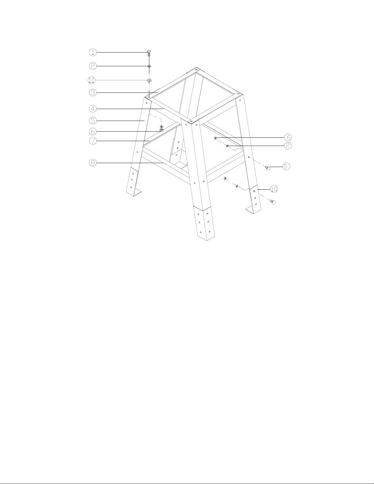
15.4.1 Stand (OPTIONAL) for JWSS-22B Scroll Saw – Exploded View
15.4.2 Stand (OPTIONAL) for JWSS-22B Scroll Saw – Parts List
Index No Part No Description Size Qty
.................. 727200S .................... Stand for Scroll Saw (#1 thru 10)............................. ........................................
1 ................ TS-0051051 .............. Hex Cap Screw ........................................................ 5/16"-18 x 1" ................. 4
2 ................ TS-0680031 .............. Flat Washer ............................................................. 5/16" ............................ 32
3 ................ JWSS22B-103 ........... Top Short Brace....................................................... ...................................... 2
4 ................ JWSS22B-104 ........... Top Long Brace ....................................................... ...................................... 2
5 ................ JWSS22B-105 ........... Leg ........................................................................... ...................................... 4
6 ................ TS-0570021 .............. Hex Nut .................................................................... 5/16"-18 ...................... 28
7 ................ JWSS22B-107 ........... Bottom Short Brace ................................................. ...................................... 2
8 ................ JWSS22B-108 ........... Bottom Long Brace .................................................. ...................................... 2
9 ................ JWSS22B-109 ........... Round Hd. Carriage Bolt, b.oxide ............................ 5/16"-18 x 1/2” ............ 24
10 .............. JWSS22B-110 ........... Leg Extension .......................................................... ...................................... 4
11 .............. JWSS22B-111 ........... Rubber washer (included with saw hardware) ......... ...................................... 4
.................. JWSS22B-SHK ......... Stand Hardware Kit (#1,2,6,9) ................................. ........................................
28

16.0 Electrical Connections – JWSS-22B Scroll Saw
29

17.0 Warranty and service
JET® warrants every product it sells against manufacturers’ defects. If one of our tools needs service or repair, please
contact Technical Service by calling 1-800-274-6846, 8AM to 5PM CST, Monday through Friday.
Warranty Period
The general warranty lasts for the time period specified in the literature included with your product or on the official
JET branded website.
• JET products carry a limited warranty which varies in duration based upon the product. (See chart below)
• Accessories carry a limited warranty of one year from the date of receipt.
• Consumable items are defined as expendable parts or accessories expected to become inoperable within a
reasonable amount of use and are covered by a 90 day limited warranty against manufacturer’s defects.
Who is Covered
This warranty covers only the initial purchaser of the product from the date of delivery.
What is Covered
This warranty covers any defects in workmanship or materials subjec t to the limitations stated below. This warranty
does not cover failures due directly or indirectly to misuse, abuse, negligence or accidents, normal wear-and-tear,
improper repair, alterations or lack of maintenance. JET woodworking machinery is designed to be used with Wood.
Use of these machines in the processing of metal, plastics, or other materials outside recommended guidelines may
void the warranty. The exceptions are acrylics and other natural items that are made specifically for wood turning.
Warranty Limitations
Woodworking products with a Five Year Warranty that are used for commercial or industrial purposes default to a
Two Year Warranty. Please contact Technical Service at 1-800-274-6846 for further clarification.
How to Get Technical Support
Please contact Technical Service by calling 1-800-274-6846. Please note that you will be asked to provide proof
of initial purchase when calling. If a product requires further inspection, the Technical Service representative will
explain and assist with any additional action needed. JET has Authorized Service Centers located throughout the
United States. For the name of an Authorized Service Center in your area call 1-800-274-6846 or use the Service
Center Locator on the JET website.
More Information
JET is constantly adding new products. For complete, up-to-date product information, check with your local distributor
or visit the JET website.
How State Law Applies
This warranty gives you specific legal rights, subject to applicable state law.
Limitations on This Warranty
JET LIMITS ALL IMPLIED WARRANTIES TO THE PERIOD OF THE LIMITED WARRANTY FOR EACH PRODUCT.
EXCEPT AS STATED HEREIN, ANY IMPLIED WARRANTIES OF MERCHANTABILITY AND FITNESS FOR A
PARTICULAR PURPOSE ARE EXCLUDED. SOME STATES DO NOT ALLOW LIMITATIONS ON HOW LONG AN
IMPLIED WARRANTY LASTS, SO THE ABOVE LIMITATION MAY NOT APPLY TO YOU.
JET SHALL IN NO EVENT BE LIABLE FOR DEATH, INJURIES TO PERSONS OR PROPERTY, OR FOR
INCIDENTAL, CONTINGENT, SPECIAL, OR CONSEQUENTIAL DAMAGES ARISING FROM THE USE OF OUR
PRODUCTS. SOME STATES DO NOT ALLOW THE EXCLUSION OR LIMITATION OF INCIDENTAL OR
CONSEQUENTIAL DAMAGES, SO THE ABOVE LIMITATION OR EXCLUSION MAY NOT APPLY TO YOU.
JET sells through distributors only. The specifications listed in JET printed materials and on official JET website are
given as general information and are not binding. JET reserves the right to effect at any time, without prior notice,
those alterations to parts , fittings, and accessory equipment which they may deem necessary for any reason
whatsoever. JET
Product Listing with Warranty Period
90 Days – Parts; Consumable items
1 Year – Motors; Machine Accessories
2 Year – Metalworking Machinery; Electric Hoists, Electric Hoist Accessories; Woodworking Machinery used
for industrial or commercial purposes
3 Year – Air Compressors
5 Year – Woodworking Machinery
Limited Lifetime – JET Parallel clamps; VOLT Series Electric Hoists; Manual Hoists; Manual Hoist
Accessories; Shop Tools; Warehouse & Dock products; Hand Tools; Air Tools
NOTE: JET is a divi sion of JP W Industri es, Inc. Ref eren ces i n this d ocumen t to JET als o ap ply to JPW Industries, I nc.,
or any of its successors in interest to the JET brand.
®
branded products are not sold in Canada by JPW Industries, Inc.
30

This page intentionally left blank.
31

427 New Sanford Road
LaVergne, Tennessee 37086
Phone: 800-274-6848
www.jettools.com
32
 Loading...