

Operating Instructions and Parts Manual
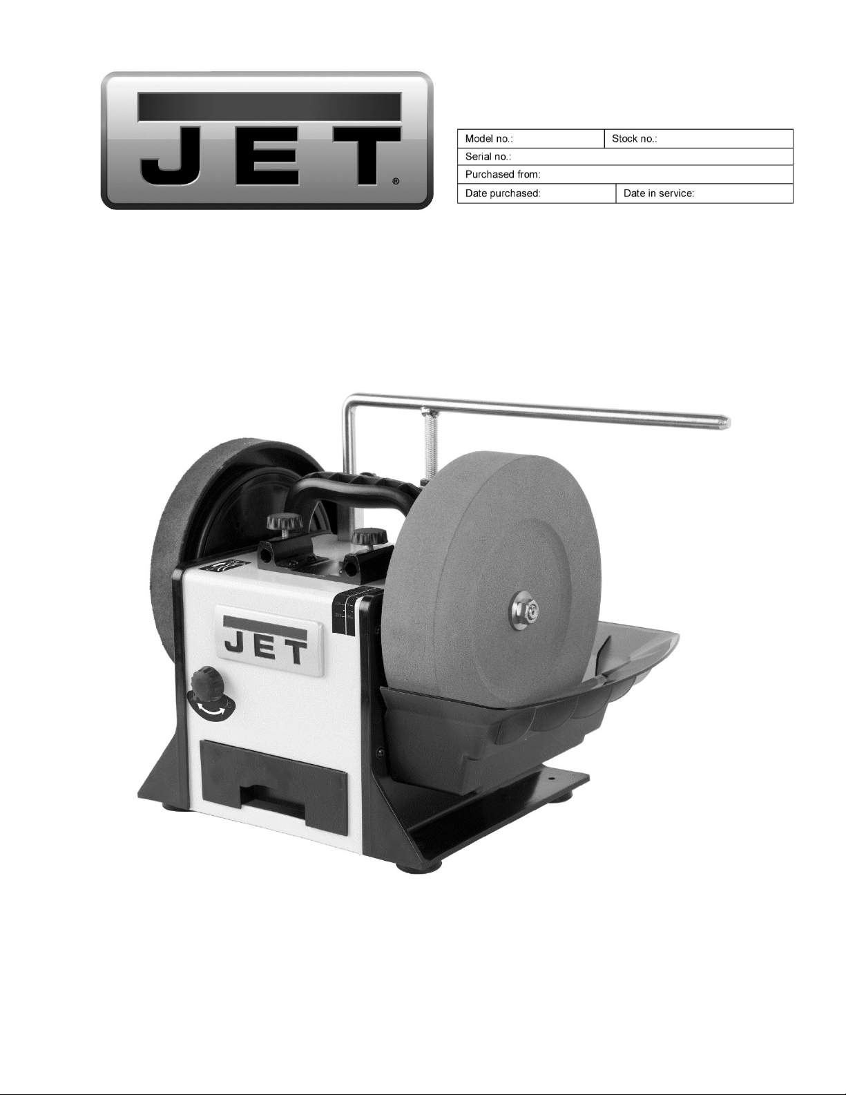
10” Slow Speed Wet Sharpener
Model JWS-10
JET
427 New Sanford Road
LaVergne, Tennessee 37086 Document No. M-727100
Ph.: 800-274-6848 Edition 1 05/2020
www.jettools.com Copyright © 2020 JET

1.0 IMPORTANT SAFETY
INSTRUCTIONS
WARNING – To reduce risk of injury:
1. Read and understand the entire owner’s manual
before attempting assembly or operation.
2. Read and understand the warnings posted on the
machine and in this manual. Failure to comply with
all of these warnings may cause serious injury.
3. Replace warning labels if they become obscured
or removed.
4. This machine is designed for grinding and
sharpening of ferrous tools only. Machining of
other materials is not permitted and may be
carried out in specific cases only after consulting
with the manufacturer.
5. This machine must be operated only by persons
familiar with its operation and maintenance and
who are familiar with its hazards.
6. Do not use this machine for other than its intended
use. If used for other purposes, JET disclaims any
real or implied warranty and holds itself harmless
from any injury that may result from that use.
7. Do not modify the machine.
8. Always wear protective eye wear when operating
machinery. Eye wear shall be impact resistant,
protective safety glasses with side shields which
comply with ANSI Z87.1 specifications. Use of eye
wear which does not comply with ANSI Z87.1
specifications could result in severe injury from
breakage of eye protection. (Everyday eyeglasses
only have impact resistant lenses; they are NOT
safety glasses.)
9. Make certain the machine is properly grounded.
10. Wear proper apparel. Do not wear loose clothing,
neckties, rings, bracelets, or other jewelry which
may get caught in moving parts. Wear protective
hair covering to contain long hair. Non-slip
footwear is recommended.
11. Wear protective clothing such as apron or safety
shoes, where the grinding activity presents a
hazard to the operator.
12. Avoid wearing gloves when possible. If a glove
must be worn to hold a long-bladed tool, use extra
caution that the glove does not catch and pull the
hand into parts of the machine or a tool blade.
13. Wear ear protectors (plugs or muffs) if the
particular work requires it.
14. Do not operate this machine while tired or under
the influence of drugs, alcohol or any medication.
15. Make certain the switch is in the OFF position
before connecting the machine to the power
supply.
16. Make certain the machine is properly grounded.
17. Make all machine adjustments or maintenance
with the machine unplugged from the power
source.
18. Remove adjusting keys and wrenches. Form a
habit of checking to see that keys and adjusting
wrenches are removed from the machine before
turning it on.
19. Keep safety guards in place at all times when the
machine is in use. If removed for maintenance
purposes, use extreme caution and replace the
guards immediately after completion of
maintenance.
20. Periodically check screws and bolts for tightness.
21. Check damaged parts. Before further use of the
machine, a guard or other part that is damaged
should be carefully checked to determine that it
will operate properly and perform its intended
function. Check for alignment of moving parts,
binding of moving parts, breakage of parts,
mounting and any other conditions that may affect
its operation. A guard or other part that is damaged
should be properly repaired or replaced.
22. Provide for adequate space surrounding work
area and non-glare, overhead lighting.
23. Keep the floor around the machine clean and free
of scrap material, oil and grease.
24. Keep visitors a safe distance from the work area.
Keep children away.
25. Make your workshop child proof with padlocks,
master switches or by removing starter keys.
26. Give your work undivided attention. Looking
around, carrying on a conversation and “horseplay” are careless acts that can result in serious
injury.
27. Keep proper footing and balance at all times so
that you do not fall into or lean against the grinding
wheel or other moving parts. Do not overreach or
use excessive force to perform any machine
operation.
28. Disconnect grinder from power source before
servicing and when changing abrasive wheels.
29. Use recommended accessories. The use of
improper accessories may cause risk of injury to
persons.
30. Turn off the machine before cleaning. Use a brush
to remove chips or debris — do not use bare
hands.
31. Never leave the grinder running unattended. Turn
power off and do not leave machine until wheels
come to a complete stop.
32. Remove loose items and unnecessary work
pieces from the area before starting the grinder.
2

33. Don’t use in dangerous environment. Don’t use
power tools in damp or wet location, or expose
them to rain. Don’t use this grinder in a flammable
environment. Keep work area well lighted.
34. Keep work area clean. Cluttered areas and
benches invite accidents.
35. Use the right tool. Don't force tool or attachment to
do a job for which it was not designed.
36. Use proper extension cord. Make sure your
extension cord is in good condition. When using
an extension cord, be sure to use one heavy
enough to carry the current your product will draw.
An undersized cord will cause a drop in line
voltage resulting in loss of power and overheating.
Table 2 (see sect. 7.2) shows the correct size to
use depending on cord length and nameplate
ampere rating. If in doubt, use the next heavier
gage. The smaller the gage number, the heavier
the cord.
37. Connection and repair work on the electrical
installation must be carried out by a qualified
electrician.
38. Tools are sharp and can lead to serious injuries;
always handle them with care.
39. Never perform any operation freehand. Tools to be
sharpened must be held in/on the appropriate
fixture and be guided firmly with both hands to
prevent them being thrown off during the
sharpening operation.
40. Never place your hand near the cutting area,
grinding stone and honing wheel while machine is
in operation.
41. Never attempt to hone a tool against the rotation –
the tool will be thrown off and the honing wheel will
be damaged.
42. Make sure the power cord does not present a
tripping hazard.
43. The stone wheel is designed for wet operation
only. Do not use the wheel dry – it will cause rapid
overheating and potential damage to wheel and
the tool being sharpened.
44. Do not overtighten wheel nut.
45. Frequently clean grinding dust from the machine.
46. Inspect abrasive wheels for cracks or other forms
of damage. Perform a “ring test” to check wheel
integrity. Do not use a faulty or damaged wheel.
47. Verify that maximum RPM of abrasive wheels is
compatible with speed of grinder. Do not remove
the blotter (label) from either side of a grinding
wheel.
48. Allow wheel to reach full RPM before starting the
grinding operation.
49. Do not crowd the work so that the wheels slow.
50. Do not grind on the side of a wheel; do all work on
the grinding face or edge. The only exception is if
the wheel is specifically rated for side grinding.
51. Do not grind aluminum or magnesium, as these
may pose a fire hazard.
52. Do not start the machine while a workpiece is
contacting a wheel.
WARNING: Some dust, fumes and gases
created by power sanding, sawing, grinding, drilling,
welding and other construction activities contain
chemicals known to the State of California to cause
cancer and birth defects or other reproductive harm.
Some examples of these chemicals are:
lead from lead based paint
crystalline silica from bricks, cement and other
masonry products
arsenic and chromium from chemically treated
lumber
Your risk of exposure varies, depending on how
often you do this type of work. To reduce your
exposure to these chemicals, work in a wellventilated area and work with approved safety
equipment, such as dust masks that are specifically
designed to filter out microscopic particles. For more
information go to
http://www. p65warnings.ca.gov/ wood.
and
http://www.p65warnings.ca.gov/
SAVE THESE INSTRUCTIONS
Familiarize yourself with the following safety notices used in this manual:
This means that if precautions are not heeded, it may result in minor injury and/or possible
machine damage.
This means that if precautions are not heeded, it may result in serious, or possibly even fatal,
injury.
3

2.0 Table of contents
Section Page
1.0 IMPORTANT SAFETY INSTRUCTIONS ....................................................................................................... 2
2.0 Table of contents ............................................................................................................................................ 4
3.0 About this manual .......................................................................................................................................... 5
4.0 Specifications ................................................................................................................................................. 6
5.0 Unpacking ...................................................................................................................................................... 8
5.1 Standard Components and Optional Accessories ...................................................................................... 8
6.0 Setup and assembly ..................................................................................................................................... 10
6.1 Mounting stone wheel .............................................................................................................................. 10
6.2 Installing water tank .................................................................................................................................. 10
6.3 Support arm (optional) .............................................................................................................................. 10
6.4 Storage ..................................................................................................................................................... 10
7.0 Electrical connections .................................................................................................................................. 10
7.1 Grounding instructions ............................................................................................................................. 10
7.2 Extension cords ........................................................................................................................................ 11
8.0 Adjustments ................................................................................................................................................. 11
8.1 Sharpening jig set up ................................................................................................................................. 11
8.2 Torque adjustment ................................................................................................................................... 12
9.0 Basic operation ............................................................................................................................................ 12
9.1 Stone wheel dressing ............................................................................................................................... 12
9.2 Tool grinding ............................................................................................................................................. 12
9.3 Tool honing ............................................................................................................................................... 13
10.0 User Maintenance ...................................................................................................................................... 13
10.1 Care of grinding wheels .......................................................................................................................... 13
10.2 Wheel replacement ................................................................................................................................ 13
10.3 Commutator brush inspection ................................................................................................................ 13
10.4 Cleaning ................................................................................................................................................. 14
10.5 Lubrication .............................................................................................................................................. 14
10.6 Additional servicing ................................................................................................................................ 14
11.0 Troubleshooting JWS-10 Wet Sharpener .................................................................................................. 15
11.1 Motor and electrical problems ................................................................................................................ 15
11.2 Mechanical and operational problems .................................................................................................... 16
12.0 Replacement Parts ..................................................................................................................................... 17
12.1.1 727100 Wet Sharpener Assembly – Exploded View ........................................................................... 18
12.1.2 727100 Wet Sharpener Assembly – Parts List .................................................................................... 19
12.2.1 727001 Rotational Base Assembly (Optional) – Exploded View ......................................................... 20
12.2.2 727001 Rotational Base Assembly (Optional) – Parts List .................................................................. 20
12.3 DT-1 Diamond Truing Tool (Optional Accessory) .................................................................................. 21
12.4 KJ-1 Knife Jig (Optional Accessory) ....................................................................................................... 22
12.5 GJ-1 Gouge Jig (Optional Accessory) .................................................................................................... 23
12.6 LKJ Long Knife Jig (Optional Accessory) ............................................................................................... 24
12.7 STJ-1 Carving Tool Jig (Optional Accessory) ........................................................................................ 25
12.8 SJ-1 Scissors Jig (Optional Accessory) ................................................................................................. 25
12.9 SWGJ-1 Side Wheel Grinding Jig (Optional Accessory) ........................................................................ 26
12.10 PLH-1 Profiled Leather Honing Wheel (Optional Accessory) ............................................................... 26
12.11 SEJ-1 Straight Edge Jig (Optional Accessory) ..................................................................................... 27
12.12 AJ-1 Axe Jig (Optional Accessory) ....................................................................................................... 27
12.13 PCJ-1 Plane Camber Jig (Optional Accessory) ................................................................................... 28
12.14 AMD-1 Angle Measuring Device (Optional Accessory) ........................................................................ 29
12.15 TR-1 Tool Rest (Optional Accessory) ................................................................................................... 30
12.16 SA-1 Support Arm Assembly ................................................................................................................ 30
12.17 SAE-1 Support Arm Extension Assembly (Optional Accessory) .......................................................... 31
13.0 Electrical connections for JWS-10 Wet Sharpener .................................................................................... 32
14.0 Warranty and Service ................................................................................................................................. 33
4

3.0 About this manual
This manual is provided by JET, covering the safe operation and maintenance procedures for a JET Model JWS10 Wet Sharpener. This manual contains basic instructions on installation, safety precautions, general operating
procedures, maintenance instructions and parts breakdown. Your machine has been designed and constructed
to provide consistent, long-term operation if used in accordance with the instructions as set forth in this document.
The operator is encouraged to familiarize him/herself with ANSI B7.1 – Safety Requirements for Use, Care and
Protection of Abrasive Wheels.
If there are questions or comments, please contact your local supplier or JET. JET can also be reached at our
web site: www.jettools.com.
Retain this manual for future reference. If the machine transfers ownership, the manual should accompany it.
Read and understand the entire contents of this manual before attempting assembly or
operation! Failure to comply may cause serious injury!
Register your product using the mail-in card provided, or register online:
http://www.jettools.com/us/en/service-and-support/warranty/registration/
5

4.0 Specifications
Table 1
Model number
Stock number 727100
Motor and Electricals
Motor Brushed DC, 120V, 1.8A
Power source required
On/off switch rocker style, waterproof
Power cable size 18AWG x 3C SJTW, 6 ft. (182 cm)
Power plug installed 5-15P, 15A, 125V
Recommended minimum circuit size 1 10A
Noise emission 2
Wheels
Stone Wheel size (dia. x width x bore) 10 x 2 x 1/2 in. (250 x 50 x 12 mm)
Stone wheel material single alundum
Stone wheel grit 220
Wheel speed, no load Variable, 90-150 RPM
Honing wheel size (dia. x width) 9 x 1-3/16 in. (230 x 30 mm)
Honing wheel material ABS+, leather tire
Main materials
Arbor SUS-304 Steel
Housing Steel
Knobs and Handle ABS Polymide
Dimensions
Base mounting holes, centers, (WxD) 10X7-7/8in (255X200mm)
Footprint (WxD) 12 x 10.15 in. (305 x 258 mm)
Overall dimensions (LxWxH) 16 x 12 x 13 in. (400 x 300 x 330 mm)
Shipping dimensions (LxWxH) 19-1/2 x 15 x 17 in. (495.3 x 381 x 431.8 mm)
Weights
Net weight 22.5 lb (10.2 kg)
Shipping weight 23.5 lb (10.7 kg)
1
subject to local/national electrical codes.
2
The specified values are emission levels and are not necessarily to be seen as safe operating levels. As workplace
conditions vary, this information is intended to allow the user to make a better estimation of the hazards and risks
involved only.
L = length, W = width, H = height, D = depth
The specifications in this manual were current at time of publication, but because of our policy of continuous
improvement, JET reserves the right to change specifications at any time and without prior notice, without incurring
obligations.
Acoustic power, idling 74.0 dB(A)
Acoustic pressure, idling 68.7 dB(A)
120V AC, single phase, 60Hz
JWS-10
6

This page intentionally left blank.
7
5.0 Unpacking
Separate all parts from the packing material. Remove the storage tray and the foam bracing from near the motor.
Check each part against Table 1. Make certain that all items in the Standard column are included in the shipping
container and accounted for before discarding any packing material.
Note: Optional Accessories are available for purchase by calling your local dealer or JET.
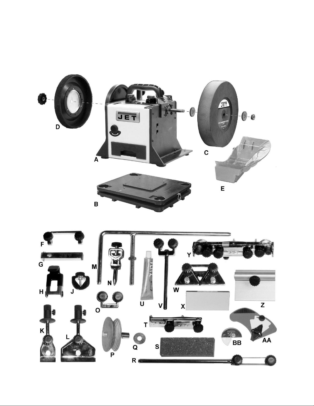
5.1 Standard Components and Optional Accessories
Figure 5-1
8

Item
A 727100 JWS-10 Slow Speed Wet Sharpener w/ accessories x
B 727001 Rotational Base Assembly x
C 707022 Stone Wheel x
D 727023 Leather Honing/Strop Wheel x
E 727000-143 Water Tank x
F,G 727003 DT-1 Diamond Truing Tool x
H 708031 AJ-1 Axe Jig x
J 708025 STJ-1 Carving Tool Jig x
K 708019 KJ-1 Knife Jig x
L 727006 LKJ Long Knife Jig x
M 727019 SA-1 Support Arm x
N,O 708020 GJ-1 Gouge Jig x
P,Q 727013 PLH-1 Profiled Leather Honing Wheel x
R 727020 SAE-1 Support Arm Extension Assembly x
S 708017 SG-1 Stone Grader x
Stock
No
Model
No
Description Standard Optional
T 727014 SEJ-1 Straight Edge Jig x
U 708023 Honing Compound x
V 727012 SWGJ-1 Side Wheel Grinding Jig x
W,X 708026 SJ-1 Scissors Jig x
Y 727016 PCJ-1 Plane Camber Jig x
Z 727018 TR-1 Tool rest x
AA 727010 AMD-1 Angle Measuring Device x
BB 708041 AMD-2 Existing Angle Measuring Device x
727200
727300 Blade Jig Set (includes H, K, W, X) x
M-727100 Manual for JWS-10 x
For assembly, operation, adjustments, maintenance and troubleshooting, please see the DVD included
with this machine.
Wood Turning Jig Set (includes J, N, O,
chisel angle jig, hex wrench)
Table 2
x
9
6.0 Setup and assembly
7.0 Electrical connections
The Wet Sharpener must be
disconnected from power during assembly.
Inspect the Wet Sharpener – if any damage is found,
notify your dealer immediately. Do not use a
damaged machine.
Clean all rust-protected surfaces with a mild solvent.
Remove shipping foam: A foam block is inserted
inside the machine to prevent the motor shaft from
resting on the drive wheel during shipment. Remove
storage drawer, turn machine on its side, and
remove the foam block before operating.
The machine should be placed on a stable and level
surface. It can be bolted down if needed.
6.1 Mounting stone wheel
Install stone wheel (C) on shaft. See Figure 5-1.
Place a washer on each side of wheel, and tighten
nut.
Note: The stone has already been trued by the
manufacturer.
6.2 Installing water tank
Install water tank (F) to lower mounting position on
side of machine. See cover photo.
Fill the tank with water up to the “MAX” marked level.
The stone will soak up a lot of water – approximately
0.5L (1/2 qt.) – within the first 15 minutes.
As the stone wears to a smaller diameter, the tank
must be moved to the upper mounting position.
6.3 Support arm (optional)
Install the accessory support arm (M, Figure 5-1) to
the vertical or the horizontal sleeves, depending
upon the specific sharpening to be done. Always
tighten knobs to secure.
6.4 Storage
The machine has an integrated drawer (E, Figure 5-
1) where the standard accessories can be stored for
quick access.
The existing angle measuring device (T, Figure 5-1)
will stick to the magnets on the designated place at
the side of the machine.
The angle measuring device (S, Figure 5-1) has
integrated magnets and will stick to any surface on
the machine body.
Electrical connections should
be made by a qualified electrician in compliance
with all relevant codes. This tool must be
properly grounded.
The wet sharpener is prewired for 120V single
phase power, and is supplied with a plug designed
for use on a circuit with a grounded outlet that looks
like the one pictured in A, Figure 6-1.
Before connecting to power source, be sure switch
is in OFF position.
It is recommended that the wet sharpener be
connected to a minimum 10-amp circuit with circuit
breaker or fuse. If using fuses, they should be timedelay fuses marked “D”. Local codes take
precedence over recommendations.
Figure 6-1: plug configurations
7.1 Grounding instructions
1. All Grounded, Cord-connected Tools:
This tool must be grounded. In the event of a
malfunction or breakdown, grounding provides a
path of least resistance for electric current to reduce
the risk of electric shock. This tool is equipped with
an electric cord having an equipment-grounding
conductor and a grounding plug. The plug must be
plugged into a matching outlet that is properly
installed and grounded in accordance with all local
codes and ordinances.
Do not modify the plug provided - if it will not fit the
outlet, have the proper outlet installed by a qualified
electrician.
Improper connection of the equipment-grounding
conductor can result in a risk of electric shock. The
conductor with insulation having an outer surface
that is green with or without yellow stripes is the
equipment-grounding conductor. If repair or
replacement of the electric cord or plug is
necessary, do not connect the equipment-grounding
conductor to a live terminal.
Check with a qualified
electrician or service personnel if the grounding
instructions are not completely understood, or if
in doubt as to whether the tool is properly
grounded. Failure to comply may cause serious
or fatal injury.
10
Use only 3-wire extension cords that have 3-prong
grounding plugs and 3-pole receptacles that accept
the tool's plug.
Repair or replace damaged or worn cord
immediately.
2. Grounded, cord-connected tools intended for use
on a supply circuit having a nominal rating less than
150 volts:
This tool is intended for use on a circuit that has an
outlet that looks like the one illustrated in A, Figure
6-1. An adapter, shown in B and C, may be used to
connect this plug to a 2-pole receptacle as shown in
B if a properly grounded outlet is not available. The
temporary adapter should be used only until a
properly grounded outlet can be installed by a
qualified electrician. This adapter is not permitted in
Canada. The green-colored rigid ear, lug, and the
like, extending from the adapter must be connected
to a permanent ground such as a properly grounded
outlet box.
7.2 Extension cords
The use of extension cords is discouraged. Try to
position equipment near the power source. If an
extension cord becomes necessary, use only threewire extension cords that have three-prong
grounding type plugs and three-prong receptacles
that accept the tool's plug. Replace or repair
damaged or worn cord immediately.
Make sure your extension cord is good condition,
and is heavy enough to carry the current your
product will draw. An undersized cord will cause a
drop in line voltage resulting in loss of power and
overheating.
Table 1 shows the correct size to use depending on
cord length and nameplate ampere rating. If in
doubt, use the next heavier gage. The smaller the
gage number (AWG), the heavier the cord.
8.0 Adjustments
8.1 Sharpening jig set up
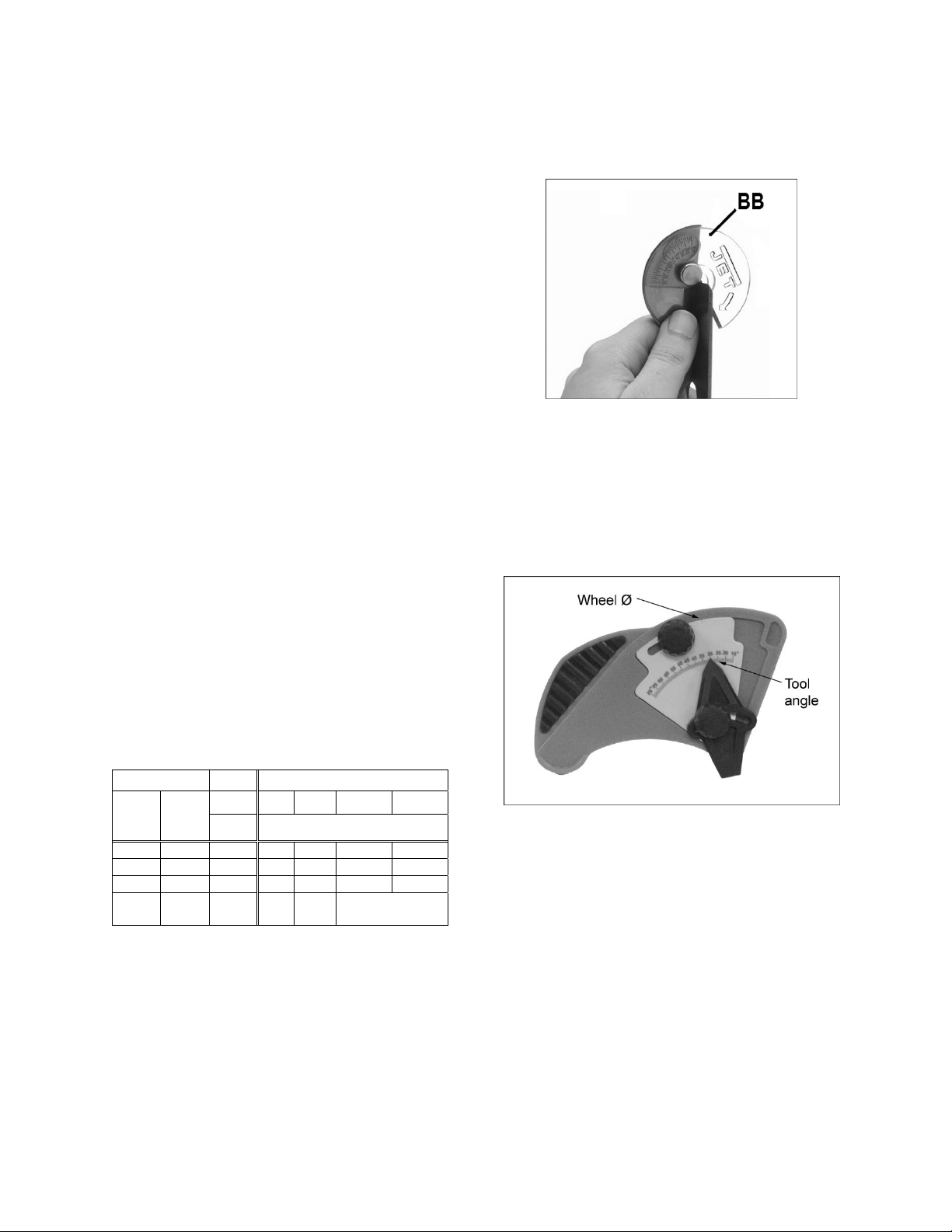
1. Use the existing angle measuring device to
establish the tool’s cutting edge (Figure 10-1).
Figure 8-1
2. Clamp the tool in the appropriate jig.
3. Adjust the support arm (Figure 10-2) and
change the tool clamping position to achieve
the correct grinding angle.
4. Set the tool angle and wheel diameter on
supplied angle measuring device. See Figure
10-2. Tighten both knobs.
Amp Rating Volts Total length of cord in feet
More
Than
Not
More
Than
0 6 18 16 16 14
6 10 18 16 14 12
10 12 16 16 14 12
12 16 14 12
Extension Cord Recommendations
120 25 50 100 150
AWG
Not
Recommended
Table 3
Figure 8-2
5. Place device on wheel and against jig, as
shown. Make additional adjustments to jig
position as needed.
NOTE: The correct stone diameter needs to be
set on the scale to achieve proper angle
reading.
11

Figure 8-3 (optional straight edge jig shown)
8.2 Torque adjustment
During heavy use, the friction drive may slip. If this
occurs, turn the torque adjust knob (Figure 10-3)
clockwise to increase pressure to the friction drive.
Note: When machine is not in use, or if additional
torque is not required, release the pressure to avoid
permanent deformation of friction drive
components.
The stone is designed for wet sharpening only.
Always fill the water tank with clean tap water, and
make sure the wheel contacts the water before
operating.
9.1 Stone wheel dressing
See Figure 9-1.
The supplied dual surface stone grader (S) dresses
the stone wheel for fine or coarse sharpening.
6. Start the machine.
7. Move the stone grader left/right evenly to dress
the stone.
8. The stone may be dressed for fine or coarse
sharpening at any time by using the correct side
of the stone grader.
Figure 8-4
9.0 Basic operation
Always wear safety glasses or
face shield. Familiarize yourself with all safety
instructions in sect. 1.0 before operating this
machine. Failure to comply may result in serious
injury.
Make sure the water level in the
tank is sufficient to keep the stone wheel wet.
Never use the wheel dry – it will cause rapid
overheating and potential damage to wheel and
tool.
The rocker switch on the Wet Sharpener body starts
and stops the machine.
The speed adjustment knob can be set to
accommodate the particular sharpening or honing
procedure needed. It can also be used to
compensate for gradual reduction in wheel
diameter.
Figure 9-1
9.2 Tool grinding
See Figure 9-2
Never perform any tool grinding operation freehand.
Tools to be sharpened must be held in the
appropriate fixture and be guided firmly so they will
not be thrown off during the sharpening process.
The wet sharpener may have to be turned to a more
convenient operating position.
Check that support arm is parallel to wheel surface.
Generally, you will achieve the best result by
grinding against the wheel. See Figure 9-2.
Figure 9-2 (optional straight edge jig shown)
12

Move the tool left/right to ensure even wear across
the wheel.
Narrow or convex cutting edges require less
pressure.
Use both hands to stabilize the tool/jig during the
sharpening process.
9.3 Tool honing
See Figure 9-3.
Honing is used to remove burrs from the sharpening
process, and to develop a very fine edge on a tool.
It is recommended to rub a very light application of
machine tool oil onto the honing leather before
proceeding.
Apply honing compound to the honing wheel. A
piece of card can be used to spread it evenly on the
wheel as the wheel is rotating on slow speed. If
honing performance begins to diminish, reapply
compound.
For quick burr removal, alternately hone both sides
of the cutting edge.
Always hone with wheel rotation. See Figure 9-3.
Do not attempt to hone against
the wheel (A, Figure 8-3); the tool will catch and
may be forced from the hand. Also the honing
wheel will be damaged.
Cracked wheels should be replaced
IMMEDIATELY. The other conditions can be
remedied with a dressing tool. See sect. 9.1.
Do not store a wet stone in freezing temperatures.
When machine is not in use, remove water tank. The
stone wheel should not sit idle in water for long
periods of time.
Frequently empty the water tank, and refill with fresh
water. Clean out debris or shavings.
10.2 Wheel replacement
Before replacing a grinding wheel, perform a “ring
test” on the replacement wheel as follows. The
wheel must be completely dry.
1. Loop a piece of string through the grinding
wheel hole and suspend the wheel by holding
up the string.
2. Tap the wheel with a piece of scrap wood or a
wooden dowel.
3. A good wheel will "ring"; a defective wheel will
"thud". Discard any wheel that does not "ring".
An internal defect may not be apparent by visual
inspection alone. The ring test may identify an
internal crack or void.
IMPORTANT: If you replace a wheel, obtain one
with a safe rated speed at least as high as the NO
LOAD RPM of the Wet Sharpener. See sect. 4 for
wheel specifications.
Figure 9-3
10.0 User Maintenance
For safety, turn the switch to OFF and remove plug
from the power source outlet before adjusting and
maintaining the wet sharpener. If the power cord is
worn, cut or damaged in any way, have it replaced
immediately.
10.1 Care of grinding wheels
In normal use, grinding wheels may become
cracked, grooved, rounded at the edges, chipped,
out of true or loaded with foreign material.
10.3 Commutator brush inspection
To maintain motor efficiency, inspect the two carbon
brushes every six months or more frequently if
machine is heavily used. Stalling or loss of power
may be a symptom of worn carbon brushes. If one
brush is worn out, replace both at the same time.
Continued use of a damaged or
worn brush may result in damage to motor
armature.
1. Unplug wet sharpener from power source.
2. Remove the drawer and the honing wheel.
3. Position wet sharpener on its side.
4. Loosen the switch box and pull it outward to
provide more space for turning the motor and
accessing both brushes. See Figure 10-1.
13

Figure 10-1
5. Use a tool to unscrew and remove cap. Note: If
standard tools will not fit the space, a box
wrench and flat head bit can be maneuvered
successfully, as shown in Figure 10-2.
Brush has worn to about 1/8-inch long.
Signs of crumbling, burning or breaking.
End of brush is rough or pitted.
Abnormal coloration of spring
Broken lead in spring
Collapsed spring
8. Install new brush (or reinstall current brush if
only inspecting) and gently press it all the way
into hole.
9. Install cap.
10. Repeat for opposite brush.
11. Retighten switch box, turn wet sharpener
upright and reinstall honing wheel and drawer.
NOTE: It is recommended that wet sharpener be
run without load for several minutes to seat new
brushes.
10.4 Cleaning
Metal shavings may still be hot
from recent grinding operations. Make sure
shavings and debris are cold before cleaning
the grinder.
Brush all shavings from the motor housing and
support arm. Check grinding wheel for cracks and
chips. Replace if damaged.
Frequently empty and refill the water tank. Clean out
any shavings or sludge from the bottom.
Figure 10-2
6. The spring will disengage brush from hole.
(Notice orientation of brush as you remove it; it
should be inserted in the same manner;
curvature of brush will match curvature of
motor.)
7. Pull out brush and inspect. Brush should be
replaced if any of the following are discovered:
Avoid use of the following
cleaning chemicals or solvents: gasoline,
carbon tetrachloride, chlorinated solvents,
ammonia and household detergents containing
ammonia.
10.5 Lubrication
All motor bearings are permanently lubricated and
sealed at the factory and require no additional
lubrication.
10.6 Additional servicing
Any other servicing should be performed by an
authorized service representative.
14

11.0 Troubleshooting JWS-10 Wet Sharpener
11.1 Motor and electrical problems
Table 4
* WARNING: Some corrections may require a qualified electrician.
Symptom Possible Cause Correction *
Motor will not start. Not connected to power source. Verify that plug is properly inserted into
receptacle.
Motor cord cut or abraded. Replace with new cord.
Fuse blown or circuit breaker open. Re-set. May be too many machines on
one line.
Plug on cord is faulty. Replace with new plug.
Low line voltage. Check power line for proper voltage.
Motor will not start;
fuses blow or circuit
breakers trip.
Motor slows, or fails to
develop full power.
Open circuit in motor or loose
connection.
Faulty switch. Replace switch.
Open circuit in motor or loose
connection.
Motor failure. Contact JET technical service.
Too many electrical machines
running on same circuit.
Incorrect fuse. Use time-delay fuse, or go to circuit with
Wheels cannot rotate because of
obstruction.
Undersized extension cord. Use correct size extension cord.
Short circuit in line cord or plug. Inspect cord or plug for damaged
Short circuit in motor or loose
connections.
Low line voltage. Check power line for proper voltage.
Motor overloaded. Reduce load to motor; do not press so
Inspect all lead connections on motor for
loose or open connections.
Inspect all lead connections on motor for
loose or open connections.
Turn off other machines and try again.
higher rated fuse or breaker.
Unplug and clear wheels of any
obstruction.
insulation and shorted wires.
Inspect all connections on motor for loose
or shorted terminals or worn insulation.
hard.
Motor stalls, resulting
in blown fuses or
tripped circuit.
Motor failure. Contact JET technical service.
Motor overloaded. Reduce load on motor; do not press so
hard.
Short circuit in motor or loose
connections.
Low voltage. Correct the low voltage conditions.
Incorrect fuses or circuit breakers in
power line.
Loose connections. Inspect connections.
15
Inspect connections on motor for loose or
shorted terminals or worn insulation.
Install correct fuses or breakers.

Symptom Possible Cause Correction *
Excessive vibration. Machine on uneven surface. Place machine on flat surface.
Stone wheel out of balance. Dress wheel.
One side of wheel is saturated. Allow wheel to dry. Do not leave idle
wheel immersed in water.
Loose fasteners. Check all fasteners.
11.2 Mechanical and operational problems
Table 5
Symptom Possible Cause Correction *
Wheel doesn’t hold an
edge, or wears too
rapidly.
Marring of tool edge. Debris on wheel. Dress wheel for a fresh surface. Clean
Wheel slips during
rotation.
Grinding creates a
slight angle along width
of tool.
Too much pressure being applied. Use lighter pressure; let the wheel do the
work.
Poor grade of wheel. Use quality wheels.
debris from tank, and refill with fresh
water.
Insufficient torque adjustment. Use torque adjust knob to remedy.
Screw or knob not tightened down. Tighten down wheel fasteners (do not
overtighten).
Jig is slipping. Make sure jig is tightened down.
Support arm not parallel to wheel. Adjust support arm to make parallel.
16

12.0 Replacement Parts
Replacement parts are listed on the following pages. To order parts or reach our service department, call 1-800274-6848 Monday through Friday, 8:00 a.m. to 5:00 p.m. CST. Having the Model Number and Serial Number of
your machine available when you call will allow us to serve you quickly and accurately.
Non-proprietary parts, such as fasteners, can be found at local hardware stores, or may be ordered from JET.
Some parts are shown for reference only, and may not be available individually.
17

12.1.1 727100 Wet Sharpener Assembly – Exploded View
18

12.1.2 727100 Wet Sharpener Assembly – Parts List
Index No. Part No. Description Size Qty
1 ................ 727000-101 ............... Spacer ..................................................................... Ø10x18x1.5 mm ........... 1
2 ................ 727000-102 ............... Bushing .................................................................... ...................................... 2
3 ................ 727000-103 ............... Motor Mount Shaft ................................................... ...................................... 1
4 ................ 727000-104 ............... Carbon Brush .......................................................... ...................................... 2
5 ................ 727000-105 ............... Carbon Brush Cover ................................................ ...................................... 2
6 ................ 727000-106 ............... Motor ....................................................................... Brushed DC .................. 1
7 ................ 727000-107 ............... Handle ..................................................................... ...................................... 1
8 ................ 727000-108 ............... Knob w/M6 Bolt Insert ............................................. ...................................... 2
9 ................ 727000-109 ............... Socket Head Cap Screw ......................................... M8-16 x 20 .................... 2
10 .............. 727000-110 ............... Power Cable with Plug............................................. ...................................... 1
11 .............. 727000-111 ............... Pressure Spring ....................................................... ...................................... 1
12 .............. 727000-112 ............... Self-Tapping Screw ................................................. ...................................... 2
13 .............. 727000-113 ............... Self-Tapping Screw ................................................. ST4x14 mm .................. 4
14A ............ 727000-114A ............. Switch Assembly (#14 thru 18) ................................ ...................................... 1
14 .............. 727000-114 ............... Waterproof On/Off Switch ........................................ ...................................... 1
15 .............. 727000-115 ............... Speed Actuator (Potentiometer) .............................. ...................................... 1
16 .............. 727000-116 ............... Switch Box Cover .................................................... ...................................... 1
17 .............. 727000-117 ............... Speed Switch Knob w/Indicator ............................... ...................................... 1
18 .............. 727000-118 ............... Switch Box ............................................................... ...................................... 1
19 .............. 727000-119 ............... Honing Wheel Lock Knob ........................................ ...................................... 1
20 .............. 727000-120 ............... Self-Tapping Screw ................................................. ST4x6 mm .................... 3
21 .............. 727000-121 ............... Honing Wheel End Cover ........................................ ...................................... 1
22 .............. 727023 ...................... Honing Wheel with Leather ..................................... ...................................... 1
23 .............. 727000-123 ............... Lock Nut .................................................................. ...................................... 1
24 .............. TS-2360121 .............. Flat Washer ............................................................. M12x24x1.5 .................. 2
25 .............. 727000-125 ............... Drive Wheel ............................................................. ...................................... 1
26 .............. 727000-126 ............... Self-Tapping Screw ................................................. ST3.5x6 mm ................. 8
27 .............. 727000-127 ............... Slide Bearing Cover ................................................. ...................................... 2
28 .............. 727000-128 ............... Slide Bearing ........................................................... ...................................... 2
29 .............. 727000-129 ............... Pin ........................................................................... ...................................... 1
30 .............. 727000-130 ............... Left Machine Support .............................................. ...................................... 1
31 .............. 727000-131 ............... Vertical Support ....................................................... ...................................... 2
32 .............. 727000-132 ............... Washer .................................................................... Ø18.5x24x0.6 mm ........ 2
33 .............. 727000-133 ............... Lock Nut .................................................................. ...................................... 2
34 .............. 727000-134 ............... Drive Shaft ............................................................... ...................................... 1
35 .............. 727000-135 ............... Horizontal Support Knob ......................................... ...................................... 2
36 .............. 727000-136 ............... Cord Strain Relief .................................................... 6P-4 .............................. 3
37 .............. TS-1541031 .............. Nylon LockNut ......................................................... M8 ................................. 2
38 .............. 727000-138 ............... Machine Body .......................................................... ...................................... 1
39 .............. 727000-139 ............... Water Shield ............................................................ ...................................... 1
40 .............. 707022 ...................... Stone Wheel ............................................................ ...................................... 1
41 .............. 727000-141 ............... Washer .................................................................... ...................................... 2
42 .............. TS-1540081 .............. Hex Nut .................................................................... M12 x 1.75 .................... 1
43 .............. 727000-143 ............... Water Tank .............................................................. ...................................... 1
44 .............. 727000-144 ............... Right Machine Support ............................................ ...................................... 1
45 .............. TS-1533032 .............. Pan Head Screw ...................................................... M5 x 10 ....................... 27
46 .............. 727000-146 ............... Rubber Foot ............................................................. ...................................... 4
47 .............. 727000-147 ............... Horizontal Support ................................................... ...................................... 1
48 .............. 727019 ...................... SA-1 Support Arm Assembly ................................... ...................................... 1
49 .............. 727000-149 ............... Drawer ..................................................................... ...................................... 1
50 .............. 727000-150 ............... Lock Nut .................................................................. .....
51 .............. 727000-151 ............... Torque Adjusting Knob ............................................ ...................................... 1
52 .............. 727000-152 ............... Cylinder Magnet ...................................................... ...................................... 1
53 .............. JET-113 ..................... JET Logo (not shown).............................................. 113 x 47 mm ................. 1
................................. 1
19

12.2.1 727001 Rotational Base Assembly (Optional) – Exploded View
12.2.2 727001 Rotational Base Assembly (Optional) – Parts List
Index No. Part No. Description Size Qty
.................. 727001 ...................... Rotational Base Assembly (#1 thru 7) ..................... ........................................
1 ................ 727001-101 ............... Cross Pan Head Screw with flat washer ................. M4x10 ........................... 8
2 ................ 727001-102 ............... Rubber Foot ............................................................. ...................................... 4
3 ................ 727001-103 ............... Lower Part of Base .................................................. ...................................... 1
4 ................ 727001-104 ............... Rotating Assembly ................................................... ...................................... 1
5 ................ TS-1503051 .............. Socket Head Cap Screw ......................................... M6x20 ........................... 4
6 ................ 727001-106 ............... Upper Part of Base .................................................. ...................................... 1
7 ................ 727001-107 ............... Locating Pin Assembly ............................................ ...................................... 1
20

12.3 DT-1 Diamond Truing Tool (Optional Accessory)
Stock # 727003
Index No Part No Description Size Qty
1. ............... 727003-101 ............... Lock Screw .............................................................. ...................................... 1
2. ............... 727003-102 ............... Diamond Tip ............................................................ ...................................... 1
3 ................ 727000-108 ............... Knob w/M6 Bolt Insert ............................................. ...................................... 2
4 ................ 727003-104 ............... Holder ...................................................................... ...................................... 1
5 ................ 727003-105 ............... Square Tube ............................................................ ...................................... 1
6 ................ 727003-106 ............... Tube End Cover ...................................................... ...................................... 1
21

12.4 KJ-1 Knife Jig (Optional Accessory)
Stock # 708019
Index No Part No Description Size Qty
1. ............... 708019-101 ............... Knob ........................................................................ ...................................... 1
2. ............... 708019-102 ............... Adjusting Knob ........................................................ ...................................... 1
3 ................ 708019-103 ............... Top Plate ................................................................. ...................................... 1
4 ................ 708019-104 ............... Knob ........................................................................ ...................................... 1
5 ................ 708019-105 ............... Handle ..................................................................... ...................................... 1
6 ................ 708019-106 ............... Bottom Plate ............................................................ ...................................... 1
7 ................ 708019-107 ............... Brass Insert ............................................................. ...................................... 2
8 ................ 708019-108 ............... Cone Spring ............................................................. ...................................... 2
22

12.5 GJ-1 Gouge Jig (Optional Accessory)
Stock # 708020
Index No Part No Description Size Qty
1. ............... 708020-101 ............... Knob ........................................................................ ...................................... 1
2 ................ 708020-102 ............... Brass Insert ............................................................. ...................................... 1
3 ................ 708020-103 ............... Body ........................................................................ ...................................... 1
4 ................ 708020-104 ............... Rubber Ring ............................................................ ...................................... 1
5 ................ 708020-105 ............... Brass End Piece ...................................................... ...................................... 1
6 ................ TS-1540041 .............. Hex Nut .................................................................... M6 ................................. 1
7 ................ 708020-107 ............... Pivot ......................................................................... ...................................... 1
8 ................ 708020-108 ............... Holder ...................................................................... ...................................... 1
9 ................ 727000-108 ............... Knob w/M6 Bolt Insert ............................................. ...................................... 2
10 .............. TS-1503061 .............. Socket Head Cap Screw ......................................... M6x25 ........................... 1
23

12.6 LKJ Long Knife Jig (Optional Accessory)
Stock # 727006
Index No Part No Description Size Qty
1. ............... 727006-101 ............... Top Plate ................................................................. ...................................... 1
2 ................ 708019-102 ............... Adjusting Knob ........................................................ ...................................... 1
3 ................ 708019-101 ............... Knob ........................................................................ ...................................... 1
4 ................ 708019-107 ............... Brass Insert ............................................................. ...................................... 2
5 ................ 727006-105 ............... Bottom Plate ............................................................ ...................................... 1
6 ................ 708019-108 ............... Cone Spring ............................................................. ...................................... 2
7 ................ 708019-105 ............... Handle ..................................................................... ...................................... 1
8 ................ 708019-104 ............... Knob ........................................................................ ...................................... 1
24

12.7 STJ-1 Carving Tool Jig (Optional Accessory)
Stock # 708025
Index No Part No Description Size Qty
1. ............... 708016-101 ............... Knob ........................................................................ ...................................... 1
2 ................ 708025-102 ............... Body ........................................................................ ...................................... 1
3 ................ 708025-103 ............... Brass Insert ............................................................. ...................................... 1
STJ-1 – Carving Tool Jig SJ-1 – Scissors Jig
12.8 SJ-1 Scissors Jig (Optional Accessory)
Stock # 708026
Index No Part No Description Size Qty
1. ............... 708019-101 ............... Knob ........................................................................ ...................................... 2
2 ................ 708019-102 ............... Adjusting Knob ........................................................ ...................................... 2
3 ................ 708026-103 ............... Top Plate ................................................................. ...................................... 2
4 ................ 708019-108 ............... Cone Spring ............................................................. ...................................... 4
5 ................ 708026-105 ............... Bottom Plate ............................................................ ...................................... 1
6 ................ 708019-107 ............... Brass Insert ............................................................. ...................................... 4
7 ................ 708026-107 ............... Plastic Slide Sheet ................................................... ...................................... 1
8 ................ 708026-108 ............... Scissors Jig Rest ..................................................... ...................................... 1
9 ................ 727000-108 ............... Knob w/M6 Bolt Insert ............................................. ...................................... 1
25

12.9 SWGJ-1 Side Wheel Grinding Jig (Optional Accessory)
Stock # 727012
Index No Part No Description Size Qty
1. ............... 727000-108 ............... Knob w/M6 Bolt Insert ............................................. ...................................... 2
2 ................ 727012-102 ............... Holder ...................................................................... ...................................... 1
3 ................ 727012-103 ............... Bar ........................................................................... ...................................... 1
12.10 PLH-1 Profiled Leather Honing Wheel (Optional Accessory)
Stock # 727013
Index No Part No Description Size Qty
1. ............... 727000-141 ............... Washer .................................................................... ...................................... 2
2 ................ 727013-102 ............... Leather Wheel ......................................................... ...................................... 1
3 ................ 727013-103 ............... Shaft ........................................................................ ...................................... 1
26

12.11 SEJ-1 Straight Edge Jig (Optional Accessory)
Stock # 727014
Index No Part No Description Size Qty
1. ............... 727014-101 ............... Bushing .................................................................... ...................................... 2
2 ................ 727014-102 ............... Bottom Plate ............................................................ ...................................... 1
3 ................ 727014-103 ............... Knob ........................................................................ ...................................... 2
4 ................ 727014-104 ............... Top Plate ................................................................. ...................................... 1
5 ................ 708019-108 ............... Cone Spring ............................................................. ...................................... 2
12.12 AJ-1 Axe Jig (Optional Accessory)
Stock # 708031
Index No Part No Description Size Qty
1. ............... 727014-101 ............... Bushing .................................................................... ...................................... 2
2 ................ 708031-102 ............... Axe Holder ............................................................... ...................................... 1
27

12.13 PCJ-1 Plane Camber Jig (Optional Accessory)
Stock # 727016
Index No Part No Description Size Qty
1. ............... 727014-104 ............... Top Plate ................................................................. ...................................... 1
2 ................ 727014-103 ............... Knob ........................................................................ ...................................... 4
3 ................ 727016-103 ............... Rubber Rest ............................................................ ...................................... 2
4 ................ 727016-104 ............... Middle Plate ............................................................. ...................................... 1
5 ................ 727016-105 ............... Bottom Plate ............................................................ ...................................... 1
6 ................ 727014-101 ............... Bushing .................................................................... ...................................... 2
7 ................ 727016-107 ............... Lock Plate Brass Insert ............................................ ...................................... 2
8 ................ 727016-108 ............... Lock Plate ................................................................ ...................................... 2
9 ................ 727016-109 ............... Adjusting Screw ....................................................... ...................................... 2
10 .............. 708019-108 ............... Cone Spring ............................................................. ...................................... 4
11 .............. 727016-111 ............... Knob ........................................................................ ...................................... 1
12 .............. 727016-112 ............... Slide Plate ............................................................... ...................................... 1
13 .............. 727016-113 ............... Brass Insert ............................................................. ...................................... 2
28

12.14 AMD-1 Angle Measuring Device (Optional Accessory)
Stock # 727017
Index No Part No Description Size Qty
1. ............... 727017-101 ............... Bottom Rubber Grip ................................................. ...................................... 1
2 ................ 727017-102 ............... Angle Measuring Body ............................................ ...................................... 1
3 ................ 727017-103 ............... Top Rubber Grip ...................................................... ...................................... 1
4 ................ 727017-104 ............... Angle Measuring Dial .............................................. ...................................... 1
5 ................ 727017-105 ............... Knob ........................................................................ ...................................... 2
6 ................ 727017-106 ............... Indicator ................................................................... ...................................... 1
7 ................ 727017-107 ............... Hex Bolt ................................................................... M4x8 ............................. 1
8 ................ 727017-108 ............... Hex Bolt ................................................................... M4x14 ........................... 1
9 ................ 727017-109 ............... Cylinder Magnet ...................................................... ...................................... 1
29

12.15 TR-1 Tool Rest (Optional Accessory)
Stock # 727018
Index No Part No Description Size Qty
1. ............... 727000-108 ............... Knob w/M6 Bolt Insert ............................................. ...................................... 1
2 ................ 727018-102 ............... Tool Rest ................................................................. ...................................... 1
12.16 SA-1 Support Arm Assembly
Stock # 727019
Index No Part No Description Size Qty
1. ............... 727019-101 ............... Support Arm ............................................................ ...................................... 1
2 ................ 727019-102 ............... Adjusting Nut ........................................................... ...................................... 1
30

12.17 SAE-1 Support Arm Extension Assembly (Optional Accessory)
Stock # 727020
Index No Part No Description Size Qty
1 ................ 727020-101 ............... Extension Bar .......................................................... ...................................... 1
2 ................ 727020-102 ............... Extension Bar Base ................................................. ...................................... 1
3 ................ 727000-108 ............... Knob w/M6 Bolt Insert ............................................. ...................................... 2
31

13.0 Electrical connections for JWS-10 Wet Sharpener
32

14.0 Warranty and Service
JET warrants every product it sells against manufacturers’ defects. If one of our tools needs service or repair, please
contact Technical Service by calling 1-800-274-6846, 8AM to 5PM CST, Monday through Friday.
Warranty Period
The general warranty lasts for the time period specified in the literature included with your product or on the official
JET branded website.
JET products carry a limited warranty which varies in duration based upon the product. (See chart below)
Accessories carry a limited warranty of one year from the date of receipt.
Consumable items are defined as expendable parts or accessories expected to become inoperable within a
reasonable amount of use and are covered by a 90 day limited warranty against manufacturer’s defects.
Who is Covered
This warranty covers only the initial purchaser of the product from the date of delivery.
What is Covered
This warranty covers any defects in workmanship or materials subject to the limitations stated below. This warranty
does not cover failures due directly or indirectly to misuse, abuse, negligence or accidents, normal wear-and-tear,
improper repair, alterations or lack of maintenance. JET woodworking machinery is designed to be used with Wood.
Use of these machines in the processing of metal, plastics, or other materials may void the warranty. The exceptions
are acrylics and other natural items that are made specifically for wood turning.
Warranty Limitations
Woodworking products with a Five Year Warranty that are used for commercial or industrial purposes default to a
Two Year Warranty. Please contact Technical Service at 1-800-274-6846 for further clarification.
How to Get Technical Support
Please contact Technical Service by calling 1-800-274-6846. Please note that you will be asked to provide proof
of initial purchase when calling. If a product requires further inspection, the Technical Service representative will
explain and assist with any additional action needed. JET has Authorized Service Centers located throughout the
United States. For the name of an Authorized Service Center in your area call 1-800-274-6846 or use the Service
Center Locator on the JET website.
More Information
JET is constantly adding new products. For complete, up-to-date product information, check with your local distributor
or visit the JET website.
How State Law Applies
This warranty gives you specific legal rights, subject to applicable state law.
Limitations on This Warranty
JET LIMITS ALL IMPLIED WARRANTIES TO THE PERIOD OF THE LIMITED WARRANTY FOR EACH PRODUCT.
EXCEPT AS STATED HEREIN, ANY IMPLIED WARRANTIES OF MERCHANTABILITY AND FITNESS FOR A
PARTICULAR PURPOSE ARE EXCLUDED. SOME STATES DO NOT ALLOW LIMITATIONS ON HOW LONG AN
IMPLIED WARRANTY LASTS, SO THE ABOVE LIMITATION MAY NOT APPLY TO YOU.
JET SHALL IN NO EVENT BE LIABLE FOR DEATH, INJURIES TO PERSONS OR PROPERTY, OR FOR
INCIDENTAL, CONTINGENT, SPECIAL, OR CONSEQUENTIAL DAMAGES ARISING FROM THE USE OF OUR
PRODUCTS. SOME STATES DO NOT ALLOW THE EXCLUSION OR LIMITATION OF INCIDENTAL OR
CONSEQUENTIAL DAMAGES, SO THE ABOVE LIMITATION OR EXCLUSION MAY NOT APPLY TO YOU.
JET sells through distributors only. The specifications listed in JET printed materials and on official JET website are
given as general information and are not binding. JET reserves the right to effect at any time, without prior notice,
those alterations to parts, fittings, and accessory equipment which they may deem necessary for any reason
whatsoever. JET
Product Listing with Warranty Period
90 Days – Parts; Consumable items
1 Year – Motors; Machine Accessories
2 Year – Metalworking Machinery; Electric Hoists, Electric Hoist Accessories; Woodworking Machinery used
for industrial or commercial purposes; Air Tools
5 Year – Woodworking Machinery
Limited Lifetime – JET Parallel clamps; VOLT Series Electric Hoists; Manual Hoists; Manual Hoist
Accessories; Shop Tools; Warehouse & Dock products; Hand Tools
NOTE: JET is a division of JPW Industries, Inc. References in this document to JET also apply to JPW Industries,
Inc., or any of its successors in interest to the JET brand.
®
branded products are not sold in Canada by JPW Industries, Inc.
33

This page intentionally left blank.
34

This page intentionally left blank.
35

427 New Sanford Road
LaVergne, Tennessee 37086
Phone: 800-274-6848
www.jettools.com
36
 Loading...