


This .pdf document is bookmarked
Operating Instructions and Parts Manual
JWL-1442VS Wood Lathe
JET
427 New Sanford Road
LaVergne, Tennessee 37086 Part No. M-708358
Ph.: 800-274-6848 Revision D2 06/2014
www.jettools.com Copyright © 2014 JET

Warranty and Service
JET® warrant s ever y pro duct i t sell s against m anuf actu rers’ defec ts. If one of ou r tools needs ser vice or rep air, please
contact Technical Service by calling 1-800-274-6846, 8AM to 5PM CST, Monday through Friday.
Warranty Period
The general warranty lasts for the time period specified in the literature included with your product or on the official
JET branded website.
• JET products carry a limited warranty which varies in duration based upon the product. (See chart below)
• Accessories carry a limited warranty of one year from the date of receipt.
• Consumable items are defined as expendable parts or accessories expected to become inoperable within a
reasonable amount of use and are covered by a 90 day limited warranty against manufacturer’s defects.
Who is Covered
This warranty covers only the initial purchaser of the product from the date of delivery.
What is Co vered
This warranty covers any defects in workmanship or materials subject to the limitations stated below. This warranty
does not cover failures due directly or indirectly to misuse, abuse, negligence or accidents, normal wear-and-tear,
improper repair, alterations or lack of maintenance.
Warranty Limitations
Woodworking products with a Five Year Warranty that are used for commercial or industrial purposes default to a
Two Year Warranty. Please contact Technical Service at 1-800-274-6846 for further clarification.
How to Get Technical Support
Please contact Technical Service by calling 1-800-274-6846. Please note that you will be asked to provide pro of
of initia l p u rch a s e whe n calling. If a product requires further inspection, the Technical Service representative will
explain and assist with any additional action needed. JET has Authorized Service Centers located throughout the
United States. For the name of an Authorized Service Center in your area call 1-800-274-6846 or use the Service
Center Locator on the JET website.
More Informa t io n
JET is constantly adding new products. For complete, up-to-date product information, check with your local distributor
or visit the JET website.
How S tate Law A pplies
This warranty gives you specific legal rights, subject to applicable state law.
Limitations on This Warranty
JET LIMITS ALL IMPLIED WARRANTIES TO THE PERIOD OF THE LIMITED WARRANTY FOR EACH PRODUCT.
EXCEPT AS STATED HEREIN, ANY IMPLIED WARRANTIES OF MERCHANTABILITY AND FITNESS FOR A
PARTICULAR PURPOSE ARE EXCLUDED. SOME STATES DO NOT ALLOW LIMITATIONS ON HOW LONG AN
IMPLIED WARRANTY LASTS, SO THE ABOVE LIMITATION MAY NOT APPLY TO YOU.
JET SHALL IN NO EVENT BE LIABLE FOR DEATH, INJURIES TO PERSONS OR PROPERTY, OR FOR
INCIDENTAL, CONTINGENT, SPECIAL, OR CONSEQUENTIAL DAMAGES ARISING FROM THE USE OF OUR
PRODUCTS. SOME STATES DO NOT ALLOW THE EXCLUSION OR LIMITATION OF INCIDENTAL OR
CONSEQUENTIAL DAMAGES, SO THE ABOVE LIMITATION OR EXCLUSION MAY NOT APPLY TO YOU.
JET sells through distributors only. The specifications listed in JET printed materials and on official JET website are
given as general information and are not binding. JET reserves the right to effect at any time, without prior notice,
those alterations to parts, fittings, and accessory equipment which they may deem necessary for any reason
whatsoever. JET
Product Listing with Warranty Period
90 Days – Parts; Consumable items; Light-Duty Air Tools
1 Year – Motors; Machine Accessories; Heavy-Duty Air Tools; Pro-Duty Air Tools
2 Year – Metalworking Machinery; Electric Hoists, Electric Hoist Accessories
5 Year – Woodworking Machinery
Limited Lifetime – JET Parallel clamps; VOLT Series Electric Hoists; Manual Hoists; Manual Hoist
Accessories; Shop Tools; Warehouse & Dock products; Hand Tools
NOTE: JET is a division of JPW Industries, Inc. References in this document to JET also apply to JPW Industries,
Inc., or any of its successors in interest to the JET brand.
®
branded products are not sold in Canada by JPW Industries, Inc.
2

Table of Contents
Warranty and Servic e .............................................................................................................................. 2
Table of Contents .................................................................................................................................... 3
Warnings ................................................................................................................................................. 4
Introduction ............................................................................................................................................. 6
Specifica tions ................................................................................................................ .......................... 6
Shipping Contents ................................................................................................................................... 7
Contents of the Shipping Containers .................................................................................................... 7
Unpacking and Clean- Up ..................................................................................................................... 7
Assembly ................................................................................................................................................ 7
Stand Legs .......................................................................................................................................... 7
Tool Rest ............................................................................................................................................. 8
Stand Shelf .......................................................................................................................................... 8
Grounding Inst r uc tions ............................................................................................................................. 9
Controls and Feat ur es ........................................................................................................................... 10
Lathe Tools ........................................................................................................................................... 12
Operations............................................................................................................................................. 1 3
Stock Selection .................................................................................................................................. 13
Roughing Out ..................................................................................................................................... 13
Beads ................................................................................................................................................ 14
Coves ......................................................................................................................... ....................... 14
“V” Cuts ............................................................................................................................................. 14
Sanding and Finishing ........................................................................................................................ 15
Face Plate or Chuck ........................................................................................................................... 16
Wood Selection .................................................................................................................................. 16
Checks and Cracks ............................................................................................................................ 16
Distortio n ........................................................................................................................................... 1 6
To Shape the Outside of a Bowl ......................................................................................................... 17
To Shape the Interior of a Bowl .......................................................................................................... 1 8
Adjustments .......................................................................................................................................... 19
Adjusting t he Clamping Mechanism .................................................................................................... 19
Changing the Belt and B earings ......................................................................................................... 19
Optional Accessories ............................................................................................................................. 2 0
Safety Gua r d ...................................................................................................................................... 20
Tool Bas k e t ........................................................................................................................................ 20
Parting ............................................................................................................................................... 14
Tools for Bo wl Turning ....................................................................................................................... 16
Sanding and Finishing a Bowl ............................................................................................................ 18
Troubleshooting ..................................................................................................................................... 21
Parts ..................................................................................................................................................... 21
Ordering Replacement Parts .............................................................................................................. 21
Bed Assembly Parts List .................................................................................................................... 22
Headstock Assembly – Parts List ....................................................................................................... 23
Headstock Assembly .......................................................................................................................... 25
Stand Assembly ................................................................................................................................. 26
Safety Gua r d As sembly.......................................................................................................... ............ 2 7
Basket Assembly ............................................................................................................................... 27
Wiring Diagram ...................................................................................................................................... 28
Appendix – Indexer Positions................................................................................................................. 29
The specifications in this manual are given as general information and are not binding. J E T, reserves the
right to eff ect, at any tim e and wit hout pri or notic e, changes or alt erat ions to par ts, fi tti ngs, and accessory
equipment deemed nec essary for any reason whatsoever.
3

Warnings
1. Read and understand the ent ire owner’s manual befor e att em pting assembly or operation.
2. This wood lathe is designed and intended for use by properly trained and experienced personnel
only. If you are not famili ar with the proper and safe operati on of a wood lathe, do not use it until the
proper trai ning and k nowledge have been obtained.
3. Always wear approved safety glasses/fac e shi el ds whil e usi ng this machine.
4. Make certain t he machine is properly grounded.
5. Before operating the machi ne, remove tie, rings, watches, ot her jewelry , and roll sleev es up past the
elbows. Remove all loose clothing and confine long hair. Do not wear gloves.
6. Keep the floor around the machine clean and free of scrap material, oil and grease.
7. Keep machine guards i n place at all times when the m achine is in use. If r emoved for maintenanc e
purposes, use extreme caution and replace the guards immediately.
8. Do not over r each. Maintain a bal anced stance at all tim es, so that you do not fall or l ean against
blades or other moving parts.
9. Make all machine adjustments or maintenance with the machine unplugged from the power source.
10. Use the r ight tool. Do not force a tool or att ac hm ent t o do a job that it was not desi gned to do.
11. Replace warning labels if they become obscured or removed.
12. M ak e c er tain the switch is in the OFF position before connecti ng the machine to the power supply.
13. Giv e your work undiv i ded at tenti on. Looki ng around, c arr yi ng on a conversation and " hor se-play " are
careless acts that can r esul t in serious injury.
14. K eep v isitors a safe distanc e from the work area.
15. Use recom mended accessories; i mproper accessories m ay be hazar dous.
16. Read and understand warnings posted on t he machine and i n this manual. Failure to comply with all
of these warnings m ay cause serious injury.
17. Some dust created by power sanding, sawing, grinding, drilling and other construction activities
contain chemi cals known to cause cancer , bir th defects or other r eproductiv e harm . Some exampl es
of these chemic als are:
Lead from lead based paint.
Crystalline silica from bricks, cement and ot her masonry products.
Arsenic and chromium from chemically treated lumber .
Your risk of exposure varies, depending on how often you do this type of work. To reduce your
exposure to these chemicals, work in a well-ventilated area and work with approved safety
equipment, such as face or dust masks that are specifically designed to filter out microscopic
particles.
18. Do not operate this lat he while under the influence of drugs, alcohol or any medication.
19. Keep tool s sharp and clean f or safe and best performanc e. Dull tools can grab i n the work and be
jerked from t he operator ' s hands causi ng serious injury.
20. Check the c ondition of the stock t o be turned. M ake sure it is free of knots, warpage, chec ked ends,
improperly m ade or cured glue joints and other c onditions which can cause it to be thrown out of the
lathe.
21. S ec ur ely fasten spur/live centers to the material being used.
22. Chec k c enters and center sockets in the headstock and tailstoc k to be sure they are free of dirt or rust
and oil lightly bef or e insert ing centers.
4

23. T est each set-up by revolv ing the work by hand t o insure i t clears the t ool rest and be d. Check the
setup at the lowest speed befor e increasing it to the operating speed.
24. Use the c or r ec t cutting tool for the oper ation to be performed and keep all tools sharp.
25. Use low speeds for roughing and for long or large diameter work. If vibration occurs, stop the
machine and corr ect the cause. See the speed recommendati on chart below:
Diameter of Work Roughing RPM
Under 2” 1520 3000 3000
2” to 4” 760 1600 2250
4” to 6” 510 1080 1500
6” to 8” 380 810 1125
8” to 10” 300 650 900
10” to 12” 255 540 750
12” to 14” 220 460 640
General Cutting
RPM
Finishing RPM
Speed Recommendations
26. W hen sanding, remov e the tool rest from the machine, apply light pressure and u se a slow speed to
avoid heat buildup.
27. W hen tur ning lar ge di ameter pi eces, such as bo wls, al ways operat e the l at he at l ow speeds. S ee the
speed recomm endation chart.
28. Do not at tempt to engage the spindle lock pin until the spindle has stopped. If leaving the machine
area, turn it off and wait until the spindle stops before depart ing.
29. Make no adjustments except speed changes with the spindle rotating and always disconnect the
machine from the power source when performing maintenance to avoid accidental starting or
electric al shock.
30. P r ov ide for adequate space surrounding work area and non-glar e, overhead lighting.
31. When stopping t he lathe, never grab the part or faceplate to slow it down. Let t he work coast to a
stop.
32. Use only JET factory authorized replacement parts and accessories; otherwise, the warranty and
guarantee are null and void.
33. Do not use t his JET wood lat he for other than i ts intended purpo se. If used for ot her purposes, JET ,
disclaim s any real or i mplied warrant y and h olds itsel f harml ess from any injury t hat may r esult f rom
that use.
Familiariz e you rself with the following safety no tices used in this manual:
This means that if precautions are not heeded, it may result in minor injury and/or
possible machine damage.
This means that if precauti ons are not heeded, it may result in serious injury or possibly
even death.
5

Introduction
This manual is provided by JET , covering the safe operat ion and maintenance pr ocedures for a Model
JWL-1442VS W ood Lathe. This manual contains instruct ions on install ation, safety prec autions, general
operating proc edures, maintenance i nstructions and part s breakdown. This m achine has been designed
and construct ed to provi de y ear s of trouble free oper ation if used in acc or danc e to instruc tions set for th in
this manual. If there are any questions or comments, please contact either your local supplier or JET. J ET
can also be reached at our web site: www.jettools.c om .
Specifications
Model Number .................................................................................................................... JWL-1442VSK
Stock Number.............................................................................................................................. 708358K
Motor ........................................................... TEFC 1HP, 1PH, 115V/230V, Prewired 115V. 60Hz, 11/ 5.5A
Switch .................................................................................................... manual, paddle style with lockout
Construction:
Headstock ............................................................................................................................... cast iron
Tailstock .................................................................................................................................. cast iron
Bed.......................................................................................................................................... cast iron
Tool Rest ................................................................................................................................. cast iron
Stand ....................................................................................................................................... cast iron
General Dimensions:
Swing Over Bed (in.) ......................................................................................................................... 14
Swing Over Tool Rest Base (in.) ....................................................................................................... 10
Distance Between Centers, maximum (in.) ........................................................................................ 42
Headstock:
Spindle Thread, Inboard (in.).................................................................................................... 1 x 8TPI
Spindle Thread, Outboard (in. ) .................................................................................. 3/4-16 UNF (L.H.)
Hole through Spindle (in.) ................................................................................................................ 3/8
Spindle Center to Floor, approx. (in.)........................................................................................... 43-1/2
Spindle Taper .........................................................................................................................#2 Morse
Headstock Rotation (deg.) .............................................................................................................. 360
Positive Stops (deg.) .....................................................................................45, 90, 135, 180, 270, 360
Spindle Speeds (RPM) ........................................ (eight): 450, 600, 850, 1100, 1500, 1900, 2300, 3000
Drive Pulley System .................................................................................................................. Ree ves
Locking System ............................................................................................................. cam (tool-les s)
Faceplate Provided (in.) ...................................................................................................................... 6
Indexing ..................................................................................... positive locking, 10 degree increments
Tailstock:
Hole through Tailstock (in.) .............................................................................................................. 3 /8
Tailstock Taper .......................................................................................................................#2 Morse
Ram Travel (in.) .................................................................................................................................. 4
Locking System ............................................................................................................. cam (tool-les s)
Tool Rest:
Base Locking System .................................................................................................... cam (tool-less)
Tool Rest Provided (in.) .................................................................................................................... 12
Weight:
Net, approximate (lbs.) .................................................................................................................... 355
Shipping, approximate (lbs.) ........................................................................................................... 375
The above specifications were current at the tim e this manual was publi shed, but because of our policy of
continuous impr ovement, JET reserves the ri ght to change specifications at any tim e and without pri or
notice, without incurring obligati ons.
6

Read and understand the entire
contents of this manual before attempting
assembly or o peration! Failure to comply may
cause serious inj ury.
Shipping Contents
Contents of the Shipping Containers
1 Lathe with Leg Set
1 Tailstock
1 Headstock
1 Face Plate
1 Tool Rest Body
1 Accessory Package
1 Owner’s Manual and War r anty Card
Accessory Package Box
1 Live Center
1 Spur Center
1 Index Pin
1 Wrench
1 Drift Rod
1 Tool Rest
1 Tool Rest Extension
4 Adjustable Feet
708358K
Unpacking and Clean-Up
1. Remove the shi pping container . Do not discard
any shipping material until the lathe is set up
and running properly.
2. Remove tailstock, tool rest and headstock
before lifting; see “Adjusting the Clamping
Mechanism” on Page 19 on ho w to rem ove t he
tailstock, headstock or tool rest.
3. Rem ove hex c ap bol ts f rom ski d bottom and l if t
the lathe bed, with the help from another
person, off the skid and onto the edge of a
workbench, as shown in Figure 1.
4. Clean all rust protected surfaces with a
cleaner-degreaser. Clean under the headstoc k,
tailstock and tool rest body.
Assembly
Stand Legs
At this point the headstock, tail stock and tool rest
should be removed. With help from another person,
lift the lat he bed and plac e onto a workbench.
1. Angle lathe bed so that stand leg mounting
holes are accessible, see Figure 1.
Contents of Acces s or y Pack age
Figure 1
7

2. Thr ead adjust able f eet ( A, Fig. 1) i nto stand l eg
(B, Fig. 1) . There is a flat spot on the shaft near
the foot that will accommodate a wrench.
Thread a hex nut (C, Fig. 1) onto shaft and
leave loose for now.
3. Mount the leg to lathe bed with four 5/16” flat
washers and four 5/ 16”-18 x 1-1/2” hex socket
cap screws (D, Fig. 1).
4. Repeat for the other leg.
5. Adj ust the f eet so that t he lathe rests evenly on
the floor, and tighten the nuts.
6. Reinstall headstock , tailstock and tool rest.
Tool Rest
Secure tool rest (A, Fig. 2) to tool rest body
(B, Fig. 2) by tight ening handle (C, Fig. 2).
Note: For some turning applications, you m ay need
to assemble the tool rest extension between the
tool rest body and tool rest.
Stand Shelf
You can make an ex tra shelf that r ests between the
legs if you wish, se e Figure 3. It will be useful for
storing lat he accessories, or addi ng sand bags f or
some extra weight. The two 2x4’s should be 553/4” long. The plywood should be ripped into two
equal pieces 27-13/16”L x 17”W so that it can be
assembled between the l egs. Use screws to at tach
the plywood to the 2x 4 supports.
Figure 2
Figure 3
8

Grounding Instructions
This tool must be grounded
while in use to protect the operator from
electric shock.
In the event of a malfunction or breakdown,
grounding prov i des a path of least resistanc e f or
electric current to reduce the risk of electric
shock. This tool is equipped with an electric cord
having an equipment-grounding conductor and a
grounding plug. The plug m ust be plugged into a
matching outlet that is properly installed and
grounded in accord ance wit h all l ocal codes and
ordinances.
Do not modify the pl ug provided. If it will not fit
the outlet , have the proper outlet i nstalled by a
qualified elec trician.
Improper connection of the equipmentgrounding conductor can result in a risk of
electric shock. The conductor, with insulation
having an outer surface that is green with or
without yellow stripes, is the equipmentgrounding conduct or. If repair or replacement of
the electric cord or plug is necessary, do not
connect the equipment-gr ounding conductor t o a
live terminal.
Check with a qualified electrician or service
personnel if the grounding instructions are not
completely understood, or if in doubt as to
whether the tool is properl y grounded. Use onl y
three wire ex tension cords that have three-pr ong
grounding plugs and t hree-pole recept acles that
accept the tool ’s pl ug.
Repair or replace a damaged or worn cord
immediately.
115 Volt Operation
As received from the factory, your sander is
ready to run at 115-volt oper ation. This sander,
when wired for 115 v olts, is intended f or use on
a circuit that has an outlet and a pl ug that l ooks
the one illustrated in Figure A. A temporary
adapter, which looks like the adapter as
illustrat ed in Figure B, may be used to connect
this plug to a two-pole receptacle, as shown in
Figure B if a properly grounded outlet is not
available.
must be connect ed to a permanent ground such
as a properly gr ounded outlet box, as shown in
Figure B.
The use of an extension cord is not
recommended. However, if you must use one
make sure your extension cord is in good
condition. Be sure to use one heavy enough to
carry the current your machine will draw. An
undersized cord will cause a drop in the line
voltage resul ting in power loss and ov erheating.
The following table shows the correct size to use
depending on the cord length needed and the
nameplate ampere rating. If in doubt, use the
next heavier gauge. Remember, the small er the
gauge number, the heavier the cord.
Volts Total Length of Cord in Feet
120V 25 50 100 150
AWG
12-16A 14 12 Not Recommended
230 Volt Operation
If 230V, single-phase operation is desired, the
following inst r uc tions must be followed:
1. Disconnect the mac hine from the power
source.
2. This lathe is supplied with four motor leads
that are connected for 115V operation, as
shown in Figure A. Reconnect these four
motor leads f or 230V operation, as shown in
Figure B.
2. The 115V att achment plug (A ), supplied with
the lathe, must be replaced with a UL/CSA
listed plug suitable for 230V operation (D).
Contact your l ocal A uthoriz ed Service Center
or qualified electrician for proper procedures
to install the plug. The lathe must comply with
all local and nati onal codes after the 230-volt
plug is installed.
3. The lathe wit h a 230 volt plug should only be
connected configuration (D). No adapter is
available or should be used with the 230-v olt
plug.
Important: In all cases (115 or 230 v olt s), m ak e
certain the receptacle in question is properly
grounded. If you are not sure, have a regi stered
electrici an c hec k the rec eptacle.
The temporary adapter should only be used until
a properly grounded outl et can be instal led by a
qualified electrician. This adapter is not
applicable in Canada. The green colored rigi d
ear, lug, or tab, extending from the adapter,
9

Controls and Features
E. Headst ock Lock Handle: (E, Fig. 4)
Locks the head i n position. Unlock the handle
to position the head in any l ocation along the
lathe bed. Tighten handle when properly
positioned.
F. Headstock Indexing Pin : (F, Fig. 4
Turn the knurled knob counter-clockwise to
unlock the plunger . Pull the knob out to release
the headstock. Unlock the headstock-locking
handle and rotate t he headstock. Turn k nurled
knob clockwise until it stops to lock plunger.
G. Headsto ck S pindle Lock: (G, Fig. 5)
Push in pin to keep the spindl e from turning.
Never press the headstock
spindle lock while the spi ndle is turning!
H. Headstock On/Off Switch: (H, Fig.5)
Flip the switch up to turn “ON” the lathe. Flip
the switch down to turn the lathe “OFF”.
I. Headstock On/Off Switch Key: (I, Fig. 5)
Remove key when in the “OFF” position. The
switch will not work until key is reinstalled.
J. Headst ock Speed Selector: (J, Fig. 5)
Place handle directly above the desired RPM
speed. Pull handl e out and move to the desired
speed, see Figure 6.
Figure 4
Only change speeds while the
spindle is turning!
Figure 5
Diameter
of Work
Under 2" 1500 3000
2 to 4" 600 1500
4 to 6" 450 1100
6 to 8" 450 600
8 to 10" 450 600
10 to 12" 450 600
12 to 14" 450 450
Roughing
RPM
General
Cutting
RPM
Figure 6
Finishing
RPM
3000
2250
1500
1125
900
750
640
10

K. Headst ock Faceplate: (K, Fig. 7)
Used for turni ng bowls. There are a num ber of
screw holes for mounting the workpiece.
Thread the faceplate onto the spindle in a
clockwise direction. Remove the faceplate by
pushing in headstock spindle lock and using
the provided wrench on f ac eplate flats.
L. Headstock Spur Center: (L, Fig. 7)
Used for turning between centers. Spindle
taper is MT- 2. Remov e spur center by insert i ng
drift rod t hr ough the opposite end of the spi ndle
and knocking spur cent er out.
M. Headstock Indexing Hole: (M, Fig. 7)
Thread indexing pin into the indexing hole
making sure that it locates in the spindl e hole.
There are 12 holes in the spindle 30° apart.
Three holes in the headstock casting accept
the indexing pin. These holes are 20° apart.
The combinati on of holes will allow you to mark
your workpiece for evenly spaced featur es. S ee
chart on page 29.
Figure 7
Never start the lathe with the
index pin engaged in the spi nd le!
N. Tool Rest Body Lock Handle: (N, Fig. 8)
Locks the tool rest body in position. Unlock
handle to posit ion the tool rest in any l ocation
along lathe bed. Tighten handl e when properly
positioned.
O. Tool Rest Lo ck Hand le: (O, Fig . 8)
Locks the tool rest in position. Unlock the
handle to posit ion tool rest at a specifi c angle,
or height. Tighten handle when properly
positioned.
P. Tailstock Lock Handle: (P, Fi g. 9)
Locks the tailstock in position. Unl oc k handle to
position t he tool rest i n any l ocati on along l athe
bed. Tighten handle when properly positioned.
Q. Tailstock Quill Loc k H a ndle: (Q, Fig. 9)
Locks the tailstock quill in position. Unlock
handle to position the quill. Tighten handle
when properly positioned.
R. Tai lstock Qu ill Handwheel: (R, Fig. 9)
Turn the handwheel to posi tion the quill. The
tailstock quill lock handle must be loose to
position quill .
S. Tailstock Live Center: (S, Fig. 9)
Used for turni ng bet ween center s. Quil l taper is
MT-2. Remov e live center by retracting the quill
until liv e cent er l oosens.
Figure 8
Figure 9
11

Lathe Tools
If possible, select only high quality, high speed
steel turning tools with long handles. As one
becomes profici ent in turning, a variety of speci alty
tools for specifi c applications can be acquir ed. The
following tools provide the basics for most
woodturning projects.
Roughing Gouge — used for rapidly cut raw wood
into round stock , see Figure 10.
Deep Fluted Bowl Gouge — used for turning
bowls and plates, see Figure 10.
Spindle Gouge — used for turning beads, coves
and other details, see Figure 10.
Spear — fine scraping and delicate operations,
such as the for ming of beads, par allel grooves and
shallow vees, etc , see Figure 10.
1. With a ruler locate and mark the center on each
end by going corner t o corner, see Figur e 12.
Accuracy is not critical on full rounds but
extremely important on stock where square
sections are to remain. Put a dimple in each
end of the stock wit h an awl or nail.
2. Extremely hard woods may require kerfs cut
into the spur driv e end of stock, see Fi gure 12.
You may need to dr iv e the spur center i nto the
stock with a wood mallet. Note: Never drive
stock onto spur while it is mounted in the lathe
spindle.
3. Install workpiece by i nserting the att ached spur
center into t he spi ndle taper on the headstock.
4. Bri ng tailstock into posi tion, lock it t o the bed,
and advance qui ll with the hand wheel in order
to seat the live cent er into the workpiece. Lock
the quill in place. Make sure the live center
point is centered on y our m ark.
5. Move tool rest into position. It should be
parallel to workpiece, approximately at the
centerline, and approximately 1/8" from the
closest part of the workpiece. Lock tool rest
body and tool rest in plac e.
Figure 10
Skew — used to make vees, beads, etc., see
Figure 11.
Square Scraper — used for diamet er scraping and
featureless scraping, etc, see Figure 11.
Large Domed Scraper — used to reduce ridges
on the interi or of bowls, r ound edge s of bo wls, etc,
see Figure 11.
Parting Tool — used to cut directly into the
material, or to make a cut off. Also used for
scraping and to set di am eters, see Figure 11.
For safety and best performance, keep tools
sharp. If a t ool stops cutti ng, or requires ex cessive
pressure to mak e a cut, it needs to be sharpened.
A number of brand name sharpening jigs and
fixtures are available, however, a wood turner
should learn to sharpen t ools freehand.
Mounting Workpiece Bet ween Centers
6. Rotat e workpiece by hand t o check for proper
clearance f rom tool rest. Note: You may want
to trim off the cor ners of a square workpiec e to
make turning a little easier.
7. Start lathe at lowest speed and bring it up to
the appropriat e RPM for the size of stock, see
Figure 6 page 11.
The position of the tool rest can be varied to suit
the work and operator. After you become
experienced with setting tool rest changing the
position will become second nature for the
workpiece and comfort of the user.
Figure 11
Spindle turni ng takes place between the centers of
the lathe. It requi res a spur cent er i n t he headstoc k
and a live center in the tailstock.
Figure 12
12

Operations
Stock Selection
Stock for spindles should be straight grained and
free of checks, cracks, knots and other defects. It
should be cut 1/8" to 1/4" larger than the finished
diameter and may require additional length to
remove ends if requir ed. Larger stock should have
the corners removed to produce an octagon
making the piece easier to rough down to a
cylinder, see Figur e 13.
Roughing Out
1. Use a large r oughing gouge and begin cutting
about 2” from the tailstock end of the
workpiece. Pl ace the tool on the tool rest with
the heel of the tool on the surf ac e to be cut.
2. Slowly and gent ly rai se tool handle until cutti ng
edge comes into contact with the workpiece.
Work to the right towards the end of the
workpiece. You nev er want to start at the end
of a workpiece.
3. Now continue t o work t he r est of the workpiec e.
Roll the fl ute (hollowed-out port ion) of the tool
in the dir ection of the cut , see Figur e 14. Make
long sweeping cuts in a continuous motion to
rough the piece down to a cylinder. Keep as
much of the bevel of the tool as possible in
contact with the workpiece to ensure control
and avoid catc hes.
Note: Always cut downhill, or from large
diameter to small diameter. Always work
toward the end of a workpiece, never start
cutting at the end.
Figure 13
Figure 14
4. Once the workpiece is roughed down to a
cylinder, smoot h it with a l arge ske w. Pl ace t he
cutting poi nt near the center of the chisel and
high on the workpiec e, see Figure 15. Touching
one of the points of the skew to the spinning
workpiece may cause a catch and ruin the
workpiece.
5. Add det ail s to t he workpiec e with ske w, spi ndle
gouge, etc.
Figure 15
13

Beads
1. Place the par ting tool on the tool rest and m ove
the tool forward to make the full bevel of the
tool contac t the workpiece. Gently r aise handle
to make cut to the appropriate depth.
2. Repeat for other si de of t he bead.
3. Using a small skew or spindle gouge, start in
the center bet ween the t wo cuts and cut d own
each side to form the bead. Roll the tool in
direction of cut.
Coves
1. Use a spindle gouge. Wit h the flute of the tool
at 90 degrees to the workpiece, touch the
center of the cutti ng edge to t he workpiece and
roll in towards the bottom of the cove. Stop at
the bottom; attempting to go up the opposite
side may cause the tool t o catc h.
2. Move the tool over the desired width of the
cove.
3. With the flute facing the opposite direction,
repeat step 1 for other side of cove. Stop at
bottom of cut.
Parting
Place part ing tool on t ool rest and raise the handle
until it starts to cut and continue to cut to the
desired depth.
If the cut is deep a clearance cut should be made
alongside the first cut to prevent the tool tip from
burning.
Figure 16
“V” Cuts
1. Use the long point of the skew. Note: Do not
press the long poi nt of the skew directly into the
workpiece to create the "V"; this will result in a
burned or burnished " V" wit h fi bers being r olled
up at both sides.
2. Li ghtly m ark t he cent er of t he "V " with the t ip of
the skew.
3. Mov e the point of the skew to the ri ght half of
the desired width of y our cut .
4. With the bevel parallel to the right side of the
cut, raise the handl e and push the tool i n to the
desired depth.
5. Repeat from the left side. The two cut s should
meet at the bottom and leave a clean "V" cut.
6. Additional cuts may be taken to add to either
the depth or width of t he cut.
Figure 17
Figure 18
14

Sanding and Finishing
Leaving clean cuts will reduce the amount of
sanding required. Begi n wit h a fi ne sandpaper (1 20
grit or finer). Coarser sandpaper will leave deep
scratches that are dif ficult t o remove, and dull crisp
details. Fold t he sandpaper i nto a p ad; do not wrap
sandpaper around your fingers or the workpiece.
To apply a f inish, the workpiece can be l eft on t he
lathe. Turn off lathe and use a brush, or cloth to
apply the finish. Remove excess finish before
restarting lathe. Allow drying and sanding again
with 320 or 400 grit sandpaper. Apply additional
coats of fini sh and buff.
Face Plate and Bowl Turning
Face plate t urning is normally done on the inboard
side of the headst ock over the bed see Figure 19.
You must pivot the headstock 180° for larger
workpieces.
Mounting Stoc k
Use of a face plate i s the most comm on method for
holding a block of wood for turning bowls, and
plates.
Figure 19
1. Sel ect stock at least 1/8" to 1/ 4" larger than t he
dimension on the desi r ed finished workpiece.
2. True one surface of t he workpiece for m ounting
against the fac e plate. It is best to leave ext ra
stock against the f aceplate that can be cut off
when the workpiece i s finished.
3. Using the faceplate as a template, mark the
location of the mounting holes, and drill pilot
holes of the appropriate size. If the mounting
screws on the faceplate interfere with the
workpiece, a waste block can be mounted to
the faceplate and then the waste block
mounted to t he workpiece by gl uing or screwing, see Figure 20.
4. Both waste block and workpiece should have
good flat surf ac es.
5. Push in on the spindle lock and thread face
plate and workpiece onto the spindle. Tighten
setscrews in the f ac eplate when secure.
Figure 20
15

Face Plate or Chuck
Tools for Bowl Turning
While faceplates are the simplest, most reliable
method of holding a block of wood for turning,
chucks can also be used. A chuck is not a
requirement but is handy when working on more
than one piece at a time. Rather than removing
screws, you simply open the chuck and change
workpieces. The most popular ones are four jaw
scroll chucks with a variety of jaws to
accommodate different size tenons. Most also
come with a screw chuck as well.
Wood Selection
Firewood is the cheapest, most widely available
stock to use whil e learning to tur n bowls. Develop
skill with each tool before attempting to make a
finished piece. It is best to start with dry wood,
without worrying about drying or distortion. Once
turning becomes comfortable, try green wood,
which cuts very easily. As the turner gains
experience, he or she will find extraordinary grain
and figure in the form of burls, crotches and bark
inclusions.
Checks and Cracks
Green wood will check and crack. F or best res ults,
leave logs i n as long lengths as you can handle. As
the material starts to dry, surface cracks will
develop on t he ends of t he l og. Cut off t wo to three
inches and you should find good, sound wood.
Also, cut the log in half along the pith to avoid
having it in t he finished piece. Most check s radiate
from the pi th. As you turn bo wls from green wood,
make sure you mai ntain a c onsistent wal l t hickness
throughout the piece. Leaving a piece thick in some
areas and thin in others wil l cause the wood to dry
unevenly and promote checks and cracks.
Distortion
Distortion is a problem associated with turning
green wood. It will vary from one type of wood to
the next. Typic ally, fruitwoods tend to distort m ore
than others do. It also varies wit h the time of year
the tree was cut and how the logs are stored.
The deep fluted bowl gouge is the most essential
and versati le tool f or most bowl and f aceplat e style
turning. The bowl gouge is heavier and easier to
control than other types of gouges. It also allows
removal of wood much faster and with less
vibration than other gouges. Most average sized
bowl work can be accom plished with a 3/8" or 1/2"
bowl gouge. A 1/4" bowl gouge is best suited for
smaller bowls and light finishing cuts. Larger 3/4"
and 1" bowl gouges are only used for extremely
large pieces.
Large domed scrapers can also be used to help
clean up the i nter ior surfaces of bowls. A li ght touch
with the scraper slightly tilted will eliminate some of
the ridges left by a bowl gouge.
16

To Shape the Outside of a Bowl
Odd shaped burls, crotches and other irregular
shaped blanks require special preparation before
mounting in a chuc k, or onto a faceplate.
1. Remove the bark, if there is any, from what
appears to be the center of the top of
workpiece.
2. Drive the spur center into the top of the
workpiece with a wood mallet.
3. Slip the spur center into the headstock taper
and bring the tailstock, with a live center, into
position. Lock the tailstock to the bed and
advance the spindle in order to seat the cup
center into workpiece, see Figure 21. Tighten
the quill lock.
4. Position the tool support below the centerline
and about 1/4" from the workpiece. Note: For
larger outboard turning, an optional outboard
turning stand i s used to place the tool support,
see your JET distri butor.
5. Turn the workpiece by hand to ensure proper
clearance.
6. Start t he lathe at the lowest speed and bri ng it
up to the maximum safe speed for t he size of
work to be turned, see Figure 6 on page 11. If
the machine star ts to vibrate, lower the speed
until the vibration stops.
7. Rough out the out side of the bowl with t he 1/2"
deep fluted bowl gouge, holding the tool firmly
against your hip. For best control, use your
whole body to move the gouge through the
workpiece.
8. As the bowl takes shape, work on the bottom
(tailstock end) to accommodate attaching a
face plate, see Figur e 21.
9. Turn a short t enon (about 1/8" l ong) the size of
the hole in the faceplate, see Figure 21. This
will allow centering the workpiece when the
faceplate is attached. Note: If y ou plan to use a
chuck, turn a tenon of appropriate length and
diameter to fit your chuck.
10. Stop the lathe, remove the workpiece and
attach the face plate, or chuck.
11. F inish turning t he outside of t he bowl wit h 1/2"
or 3/8" bowl gouge. Leave additional material at
the base of the bowl for support while turning
the interior. This will be removed later.
Figure 21
17

To Shape the Interior of a Bowl
Sanding and Finishing a Bowl
1. Stop the lathe and move the tailstock away.
Remove the center from the tailstock to prevent
bumping it wit h your elbow.
2. Adjust the tool support in front of the bowl just
below the centerline, at a right angle to the
lathe bed.
3. Rotate the workpiece by hand to check the
clearance.
4. Fac e off the top of t he bowl by making a li ght
shearing cut acro ss the workpi ece, fr om rim to
center.
5. Place the 1/2" bowl gouge on the tool rest at
the center of the workpi ece with t he flut e facing
the top of the bowl. The tool handle should be
level and pointed toward four o'clock, see
Figure 22.
6. Use your lef t hand to control the cut ting edge of
the gouge, while your right hand swings the
tool handle around towards your body, see
Figure 22.
The flut e should start out fac ing the top of the
workpiece, and rotate upward as it moves
deeper into the bowl to maintain a clean ev en
curve.
As the tool goes deeper into bowl,
progressively work out toward the rim. It may
be necessary to turn the tool rest into the
workpiece, as you get deeper into the bowl.
Note: Try to make one, very light continuous
movement from the rim to the bottom of the
bowl to ensure a clean, sweeping curve
through the workpi ece. Should there be a f ew
small ridges rem aining, a light cut with a large
domed scraper can even out the surface.
1. Remove the t ool rest and begin with a f ine grit
sandpaper (120 grit) and progress through
each grit, using only light pressure.
Coarser sandpaper tends to leave deep
scratches that are hard to eliminate. Use
power-sanding techniques to avoid concentric
sanding marks around your finished piece.
Avoid rounding over the rim and foot with
sandpaper. Try to keep the detail s crisp. Finish
sanding with 220 grit.
2. Remove sanding dust with tack rags, or
compressed air and, with the lathe turned off,
apply the first coat of finish. Let it stand for
several minut es and wipe off the excess. Al low
it to dry before sanding agai n with 320 or 400
grit sandpaper.
3. Turn lat he back on and mak e a separati on cut
through the base. Stop at about 3" and use a
small fi ne tooth saw to sep arate the bo wl from
the waste.
4. Apply additional finish coats and allow to dry
before buffing.
7. Develop the wall thickness at the rim and
maintain it as you work deeper into the bowl.
When the interior is finished, move the tool
support to the exterior to re-define the bottom
of the bowl. General rule of thumb: the base
should be approximately 1/3 the overall
diameter of t he bowl.
8. Work the tight area around the faceplate or
chuck with 1/4" bowl gouge.
Figure 22
18
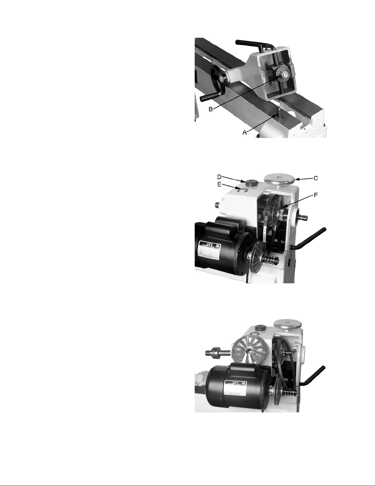
Adjustments
Adjusting the Clamping Mechanism
The clamps are pre-set at the factory and should
not need any adjustm ent . However , if adj ustment is
needed, remov e the stud (A, Fig. 23). Loosen the
locking handl e and slide the headstoc k, tail stock or
tool rest t o the edge of the bed and sli ghtly turn the
hex nut (B, Fig. 23). Slide back into position and
test the handle to mak e sure it securely locks.
Changing the Belt and Bearings
Changing belt and beari ngs can be a difficult task,
and should be performed by a JET authorized
repair station. Remove headstock and take into a
repair station for servicing.
1. Place the belt in its highest speed range. Do
not change speeds while changing t he belt or
bearings.
2. Remove the belt cover, and remove the belt
from the lower pulley , see Figure 24.
3. Loosen the two setscrews in the handwheel
enough to unthread the handwheel (C, Fig. 24).
4. Loosen t he socket head cap scre w enough to
unthread the clamping nut (D, Fig. 24).
5. Remove one e-ring ( E, Fig. 24) fr om spindle.
6. Loosen the two setscrews in the right hand
pulley (F, Fi g. 24).
7. Use a wood do wel, or al uminum stock to knoc k
the spindle towards the tailstock. Use a
material that is softer than the spindle so you
do not mushroom the end of the spindle. Go
only far enough to rem ove the right hand pull ey
and belt from spindle, see Figure 25 when
changing the bel t. Note: Mark the key way on
the pulley for easy reference when
reassembling.
Figure 23
Figure 24
8. Now you can replace the belt or bearings.
There are three beari ngs #6, 9 and 43 t hat can
be seen in the “Headstock Assembly,” on
page 25.
9. To reassemble reverse the procedure. Note:
Key way ali gnment is cri tical for installment and
proper operati on. Do not force the pull ey. When
reinstalling clamping nut thread it on to the
spindle until its snug. Then back off sl ightl y and
tighten the socket head c ap screw.
Figure 25
19
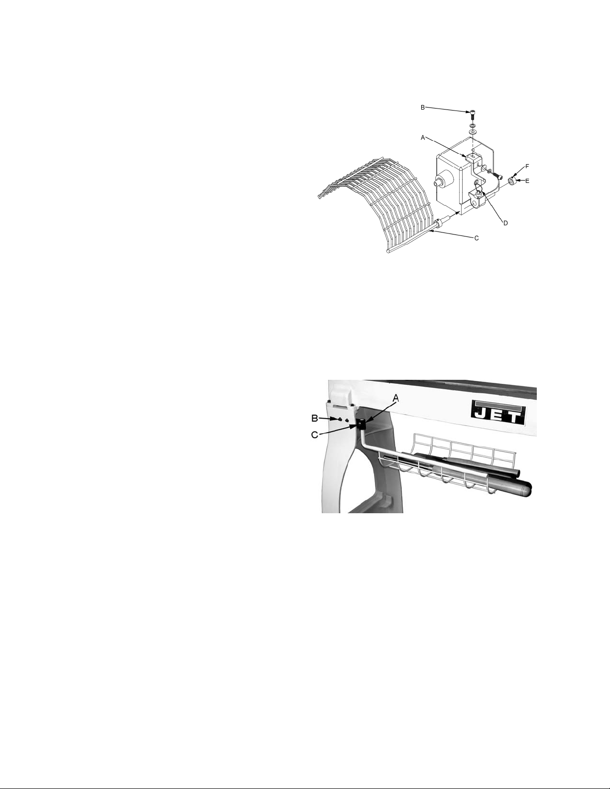
Optional A ccessories
Safety Guard
The JWL-1442VS Safety Guard is an optional
accessory.
Referring to Fi gur e 26:
1. Mount the guard bracket (A) to the headstock
with two 3/8” flat washers, two 3/8” lock
washers and t wo 3/8”-16 x 1-1/2” socket head
cap screws (B).
2. Attach the guard (C) to the guard bracket by
inserting the rod and lifting up on the plunger
(D).
3. There are two detents that will hold the guard in
place. One is for turning and the other is for
when you need the guard up and out of the
way. Simply lift up on the plunger and rotate
the guard until the plunger slips into the detent.
Tighten the bushings (E) against the bracket with
two setscrews (F) .
Tool Basket
Referring to Fi gur e 27:
1. Mount the br acket (A ) to the i nside of the lathe
leg with two 5/16”- 18 x 1-1/2” Hex Socket Cap
Screws, four 5/16” flat washers and two 5/16”
hex nuts (B).
2. The two setscrews, on the bracket should be
below the bolts and accessible for adjustment.
3. Place the arm of the tool basket into the
bracket and tighten with a 5/16”-18 x 5/8” set
screw and a 5/16” hex nut (C). Line up the
notch in the ar m wit h the setscrews so t he tool
basket can pivot.
4. Adjust the set screws on the bracket so that the
tool basket swings in a level manner. Tighten
the two hex socket cap screws.
Figure 26
Figure 27
20

Troubleshooting
Problem Possible Cause Solution
Excessive Vibr at io n.
Motor or Spindle
Stalls or Will not
Start
Motor fails to
develop full power.
Tools tend to grab
or dig in.
Tailstock Moves
When Applying
Pressure
1. Workpiec e warped, out of r ound, has
major flaw, improperly prepared for
turning, or RPM i s set too high
2. Worn spindle beari ngs
3. Worn belt
4. Motor mount bolts loose
5. Lathe on uneven surfac e
1. Excessive cut
2. Worn motor
3. Broken belt
4. Worn spindle beari ngs
5. Improper cooling on motor
6. Starting or r unning c apac itor is bad
7. Centrifugal switc h bad
1. Power line overloaded
2. Undersize wires in supply system, or
extension c or d is too long
3. Low voltage
4. Running capacitor is bad
5. Worn motor
1. Dull tools
2. Tool support set t oo low
3. Tool support set t oo far from workpiece
4. Improper tool being used
1. Excessive pressure being applied by
tailstock. Note: The screw action of
the tailstoc k is capable of applying
excessiv e pressure to workpiece and
headstock. Apply only sufficient force
by tailstock to hold workpiece securely
in place. Excessive pressure can
cause damage to machine.
2. Lathe bed and tailstock mating
surfaces are greasy or oi ly.
1. Correct problem by planing,
bandsawing, reduc e the RPM,
or scrap workpiece all together
2. Replace bearings
3. Replace belt
4. Tighten bolts
5. Shim lathe bed, or adjust feet
on stand
1. Reduce cut depth
2. Replace motor
3. Replace belt
4. Replace bearings
5. Clean sawdust from motor fan
6. Replace the starting capacitor
7. Replace centrifugal switch
1. Correct overload c ondition
2. Increase supply wir e si z e
3. Request voltage check from
power company and c orrect
low voltage condition
4. Replace running capacitor
5. Replace motor
1. Sharpen tools
2. Reposition t ool support height
3. Reposition tool support closer
to workpiece
4. Use correct tool f or operat ion
1. Slide tailstock down to t he ri ght
side of the lathe against the
stop. Move headstock into
position and apply pressure to
workpiece with tailstock.
2. Remove and clean surfac es
with a cleaner degreaser
Parts
Ordering Replacement Parts
To order parts or reach our service department, call 1-800-274-6848 Monday through Fri day (see our
website for business hours, www.jettools.com). Having the Model Number and Serial Number of your
machine available when you call will allow us to serv e you quickly and ac c urately.
21
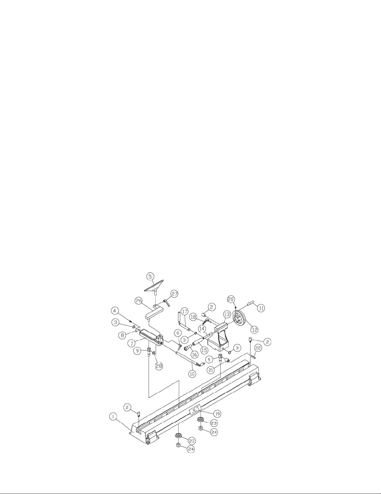
Bed Assembly Parts List
Index No. Part No. Description Size Q t y
1 ............... JWL1442-201 ..........Bed ....................................................................................................... 1
2 ............... JWL1442-202 ..........Stud ...................................................................................................... 3
3 ............... JWL1442-124 ..........C-Ring ................................................................S19 ............................ 3
4 ............... 6295703...................Hex Socket Cap Screw .......................................10-24 x 5/8” ................ 4
5 ............... JWL1442-205 ..........Tool Rest ............................................................................................... 1
6 ............... JWL1442-206 ..........Tool Support Handle .............................................................................. 1
7 ............... JWL1442-207 ..........Tool Support Base ................................................................................. 1
8 ............... JWL1442-208 ..........End Cover ............................................................................................. 1
9 ............... JWL1442-128 ..........Bolt........................................................................................................ 2
10 ............. JWL1442-210A ........Tool Support Rod .................................................................................. 1
11 ............. JWL1442-211 ..........Handle................................................................................................... 1
12 ............. JWL1442-212 ..........Handwheel ............................................................................................ 1
13 ............. JWL1442-213 ..........Tailstock ................................................................................................ 1
14 ............. JWL1442-214 ..........Lead Sc r ew ........................................................................................... 1
15 ............. JWL1442-215 ..........Quill ....................................................................................................... 1
16 ............. JWL1442-216 ..........Live Center ............................................................................................ 1
17 ............. JWL1442-217 ..........Tailstock Rod......................................................................................... 1
18 ............. JWL1442-218 ..........Tailstock Quil l Handle ............................................................................ 1
19 ............. JWL1442-219 ..........JET Label .............................................................................................. 1
20 ............. TS-0267021 .............Set Screw ...........................................................1/4”-20 x 1/4” .............. 2
21 ............. JWL1442-127 ..........Bushing ................................................................................................. 1
22 ............. JWL1442-126 ..........Key.....................................................................5 x 5 x 30 ................... 1
23 ............. JWL1442-154 ..........Clamp.................................................................................................... 2
24 ............. TS-0561081 .............Hex Nut ..............................................................3/4”-10........................ 2
26 ............. JWL1442-226
27 ............. JWL1442-227 ..........Locking Handle ...................................................................................... 1
28 ............. JWL1442-228 ..........C-Ring ................................................................S25 ............................ 1
................. JWL1442-TCA .........Tailstock Complete Assembly (not shown) ............................................. 1
................. JWL1442-TRCA .......Tool Rest Complete Assembly (not shown) ............................................ 1
..........Extension Tool Rest .............................................................................. 1
22

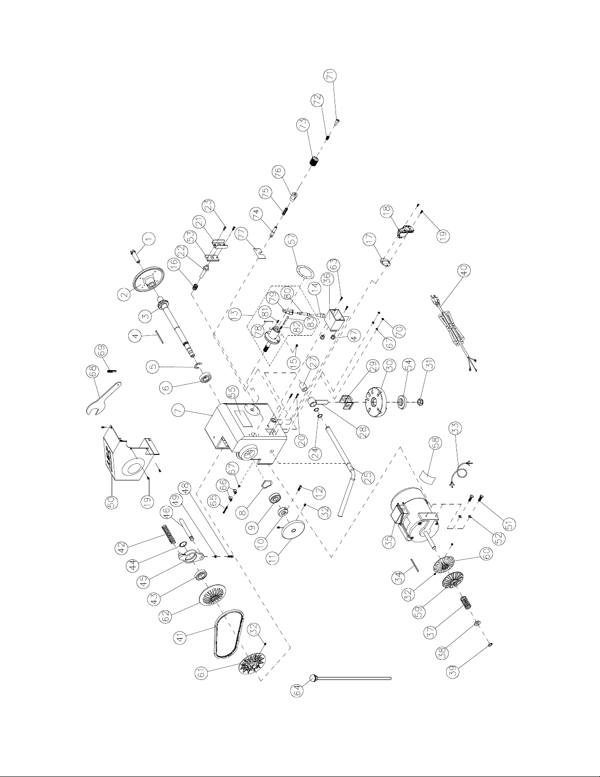
Headstock Assembly – Parts List
Index No. Part No. Description Size Q t y
1 ............... JWL1442-101 ..........Spur Center ........................................................MT2 ............................ 1
2 ............... JWL1442-102 ..........Face Plate ..........................................................6” ............................... 1
3 ............... JWL1442-103 ..........Spindle .................................................................................................. 1
4 ............... JWL1442-104 ..........Key.....................................................................4 x 4 x 80 ................... 1
5 ............... JWL1442-105 ..........E-Ring ................................................................E-19 ........................... 1
6 ............... BB-6205ZZ ..............Ball Bearing ........................................................6205ZZ....................... 1
7 ............... JWL1442-107 ..........Headstock ............................................................................................. 1
8 ............... JWL1442-108 ..........Wave Washe r ........................................................................................ 1
9 ............... BB-6304LLB ............Ball Bearing ........................................................6304LLB ..................... 1
10 ............. JWL1442-110 ..........Lock Nut .............................................................3/4”-16........................ 1
11 ............. JWL1442-111 ..........Hand wheel ........................................................................................... 1
12 ............. TS-0207031 .............Hex Socket Cap Scre w .......................................1/4”-20 x 5/8” .............. 1
13 ............. JWL1442-113A ........Speed Selector Assembly ...................................................................... 1
14 ............. JWL1442-114 ..........Handle................................................................................................... 1
15 ............. TS-081C052 ............Round Head Machine Screw ..............................10-24 x 3/4 ................. 2
16 ............. JWL1442-116 ..........Spring.................................................................................................... 1
17 ............. JWL1442-117 ..........Switch Bracket....................................................................................... 1
18 ............. JWL1442-118 ..........Switch Assembly ................................................................................... 1
19 ............. TS-081C022 ............Round Head Machine Screw ..............................10-24 x 3/8” ................ 2
20 ............. TS-081C052 ............Round Head Machine Screw ..............................10-24 x 3/4” ................ 2
21 ............. JWL1442-121 ..........Bracket .................................................................................................. 1
22 ............. JWL1442-122 ..........Spindle Lock Pin .................................................................................... 1
23 ............. TS-0206031 .............Hex Socket Cap Screw .......................................10-24 x 5/8” ................ 2
24 ............. JWL1442-124 ..........C-Ring ................................................................S19 ............................ 2
25 ............. JW
26 ............. JWL1442-126 ..........Key.....................................................................5 x 5 x 30 ................... 1
27 ............. JWL1442-127 ..........Bushing ................................................................................................. 1
28 ............. JWL1442-128A ........Bolt........................................................................................................ 1
29 ............. JWL1442-129 ..........Support B r ac k et ..................................................................................... 1
30 ............. JWL1442-130 ..........Index B r ac k et ........................................................................................ 1
31 ............. TS-0561081 .............Hex Nut ..............................................................3/4”-10........................ 1
32 ............. TS-0267021 .............Set Screw ...........................................................1/4”-20 x 1/4” .............. 6
33 ............. JWL1442-133 ..........Motor Cord ............................................................................................ 1
34 ............. JWL1442-134 ..........Key.....................................................................4 x 4 x 80 ................... 1
35 ............. JWL1442-135 ..........Motor ..................................................................1HP, 1Ph .................... 1
................. JWL1442-MF ...........Motor Fan (not shown) ........................................................................... 1
................. JWL1442-MFCA ......Motor Fan Cover (not shown) ................................................................ 1
................. JWL1442-CS ...........Centrifugal Switch (not shown) .............................................................. 1
................. JWL1442-CC ...........Capacitor Cover (not shown) ................................................................. 2
................. JWL1442-SC ...........Starting Capacitor (not shown) ............................200MFD, 125VAC ...... 1
................. JWL1442-RC ...........Running Capacitor ( not shown) ...........................25uF , 250VAC ............ 1
36 ............. JWL1442-136 ..........Switch Box ............................................................................................ 1
37 ............. JWL1442-137 ..........Spring.................................................................................................... 1
38 ............. JWL1442-138 ..........Sleeve ................................................................................................... 1
39 ............. JWL1442-139 ..........C-Ring ................................................................S16 ............................ 1
40 ............. JWL1442-140 ..........Power Cord ........................................................................................... 1
41 ............. JWL1442-141 ..........Belt.....................................................................3V-250 ....................... 1
42 ............. JWL1442-142 ..........Spring.................................................................................................... 1
43 ............. BB-6006LLB ............Ball Bearing ........................................................6006LLB ..................... 1
44 ............. JWL1442-144 ..........C-Ring ................................................................S32 ............................ 1
45 ............. JWL1442-145 ..........Shifting Lever Bracket............................................................................ 1
46 ............. JWL1442-146
47 ............. JWL1442-147 ..........Strain Relief Bushing ............................................................................. 2
48 ............. TS-0207061 .............Hex Socket Cap Scre w .......................................1/4”-20 x 1” ................. 1
49 ............. TS-0561011 .............Hex Nut ..............................................................1/4”-20........................ 1
50 ............. JWL1442-150 ..........Pulley Cover .......................................................................................... 1
L1442-125 ..........Lever ..................................................................................................... 1
..........Rack ...................................................................................................... 1
23

Headstock Assembly – Parts List
Index No. Part No. Description Size Q t y
51 ............. TS-0081031 .............Hex Head Bolt ....................................................5/16”-18 x 3/4” ............ 2
52 ............. TS-0720081 .............Lock Washer ......................................................5/16” ........................... 2
53 ............. JWL1442-153 ..........Plate ...................................................................................................... 1
54 ............. JWL1442-154 ..........Clamp.................................................................................................... 1
55 ............. JWL1442-155 ..........JET Label .............................................................................................. 1
56 ............. JWL1442-156 ..........Warning Label ....................................................................................... 1
57 ............. JWL1442-157 ..........Speed Label .......................................................................................... 1
58 ............. JWL1442-158 ..........Motor Label ........................................................................................... 1
59 ............. JWL1442-159 ..........Motor Pulley (left) .................................................................................. 1
60 ............. JWL1442-160 ..........Motor Pulley (right) ................................................................................ 1
61 ............. JWL1442-161 ..........Spindle Pulley ( left) ................................................................................ 1
62 ............. JWL1442-162 ..........Spindle Pulley ( rig h t ).............................................................................. 1
63 ............. TS-081C022 ............Round Head Machine Screw ..............................10-24 x 3/8” ................ 4
64 ............. JWL1442-164 ..........Knock Out Rod ...................................................................................... 1
65 ............. TS-081C082 ............Pan Head Screw ................................................10-24 x 1-1/2” ............. 1
66 ............. JWL1442-166 ..........Clip........................................................................................................ 1
67 ............. TS-056007 ...............Hex Nut ..............................................................10-24 .......................... 2
68 ............. JWL1442-168 ..........Spanner Wrench ................................................................................... 1
69 ............. JWL1442-169 ..........Index P in ............................................................................................... 1
70 ............. JWL1442-170 ..........Star Washer .......................................................3 /16 ” ........................... 1
71 ............. JWL1442-171 ..........Hex Socket Cap Scr e w .......................................................................... 1
72 ............. JWL1442-172 ..........Spring.................................................................................................... 1
73 ............. JWL1442-173 ..........Index K nob ............................................................................................ 1
74 ............. JWL1442-174 ..........Index S haft ............................................................................................ 1
75 ............. JWL1442-175
76 ............. JWL1442-176 ..........Index B ushi ng........................................................................................ 1
77 ............. JWL1442-PL ............Headstock Pivot Label ........................................................................... 1
78 ............. JWL1442-178 ..........Spring Pin...........................................................Ø3x25 ........................ 1
79 ............. JWL1442-179 ..........Fixed Block ............................................................................................ 1
80 ............. JWL1442-180 ..........Rod ....................................................................................................... 1
81 ............. JWL1442-181 ..........Spring.................................................................................................... 1
82 ............. JWL1442-182 ..........Spring.................................................................................................... 1
83 ............. JWL1442-183 ..........Pin......................................................................................................... 1
..........Spring .................................................................................................... 1
24
Headstock Assembly
25

Stand Assembly
Index No. Part No. Description Size Q t y
3 ............... JWL1642-203 ..........Stand .................................................................................................... 2
5 ............... JWL1642-205 ..........JET Strip e ............................................................................................. 1
6 ............... JWL1642-206 ..........Adjustable Foot ..................................................3/8”............................. 4
7 ............... TS-0561031 .............Hex Nut ..............................................................3/8”............................. 4
9 ............... TS-0208081 .............Hex Socket Cap Screw .......................................5/16”-18 x 1-1/2” ......... 8
10 ............. TS-0680032 .............Flat Washe r ........................................................5/16” ........................... 8
26

Safety Guard Assembly
Index No. Part No. Description Size Q t y
1 ............... JWL1442-301 ..........Guard Bracket ....................................................................................... 1
2 ............... TS-0270011 .............Set Screw ...........................................................5/16”-18x1/4” .............. 2
3 ............... JWL1642-187 ..........Collar .................................................................................................... 2
4 ............... TS-0680041 .............Flat Washe r ........................................................3/8”............................. 2
5 ............... TS-0720091 .............Lock Was h e r ......................................................3/8”............................. 2
6 ............... TS-0209071 .............Socket Head Cap Screw .....................................3/8”-16x1-1/2” ............. 2
7 ............... JWL1642-168 ..........Plunger.................................................................................................. 1
8 ............... JWL1642-179 ..........Guard .................................................................................................... 1
Safety Guard Assembly
Basket Assembly
Index No. Part No. Description Size Q t y
1 ............... JWL1642-228 ..........Basket ................................................................................................... 1
2 ............... TS-0270061 .............Set Screw ...........................................................5/16”-18x5/8” .............. 1
3 ............... TS-0570021 .............Hex Nut ..............................................................5/16” ........................... 3
4 ............... JWL1642-226 ..........Bracket .................................................................................................. 1
5 ............... TS-0680032 .............Flat Washe r ........................................................5/16” ........................... 4
6 ............... TS-0267021 .............Set Screw ...........................................................1/4”-20x1/4” ................ 2
7 ............... TS-0208081 .............Hex Socke t Ca p Sc re w .......................................5/16”-18x1-1/2 ” ........... 2
Basket Assembly
27

Wiring Diagram
28

Appendix – Indexer Positions
How to use the chart
A diagram of the indexer is shown at right, as
viewed from the tailstock end of the Lathe.
Points A, B and C are the holes in the head
casting. T he holes in the spindle coll ar may be
considered as numbered 1 t hr ough 12.
Example: You wish to rout 9 flutes on your
spindle blank. Locate the “9” in the “No. of
Flutes” colum n; each f l ute angl e will be 40°. The
index pin should first be inserted into hole
combination “A-1”. Make your first flute at this
position. Back off the index pin and rotate the
spindle until the index pin can be inserted into
hole combination “A-5”; this will be followed by
“A-9”. Succeeding flutes will be made with the
index pin in the B position: “B-3”, “B-7” and so
on
No. of Flute s
360° divided by...
1 360.00 A 1
2 180.00 A 1,7
3 120.00 A 1,5,9
Angle Letter # Letter # Letter #
4 90.00 A 1,4,7,10
5 72.00 -----------------------
6 60.00 A 1,3,5,7,9,11
8* 45.00 A 1,4,7,10
9 40.00 A 1,5,9 B 3,7,11 C 1,5,9
10 36.00 -----------------------
12 30.00 A 1 to 12
15 24.00 -----------------------
16 22.50 -----------------------
18 20.00 A 1,3,5 , 7,9,11 B 1,3, 5,7,9,11 C 1,3,5,7,9,1 1
20 18.00 -----------------------
24* 15.00 A 1 to 12
30 12.00 -----------------------
36 10.00 A 1 to 12 B 1 to 12 C 1 to 12
other inte resting patterns....
9 ------ A 1,5,9 B 1,5,9 C 1,5,9
NOTE: A dashed line indicates that particular s et of angles is not possible with the indexer .
* For 8 or 24 flutes, perform the first sequence, then rotate the workpiece by hand to the needed posit ion and repeat
the same sequence.
29

Notes
30

Notes
31

427 New Sanford Road
LaVergne, Tennessee 37086
Ph.: 800-274-6848
www.jetttools.com
32
 Loading...