

Page 1

This .pdf document is bookmarked
Operating Instructions and Parts Manual
22” and 25” Open-End Drum Sanders
Models JWDS-2244, JWDS-2550
JET
427 New Sanford Road
LaVergne, Tennessee 37086 Part No. M-723540B
Ph.: 800-274-6848 Edition 2 03/2019
www.jettools.com Copyright © 2018 JET
Model JWDS-2550 shown with optional closed stand
and optional infeed/outfeed tables
Page 2

1.0 IMPORTANT SAFETY
INSTRUCTIONS
WARNING – To reduce risk of injury:
1. Read and understand the entire owner's
manual before attempting assembly or
operation.
2. Read and understand the warnings posted on
the machine and in this manual. Failure to
comply with all of these warnings may cause
serious injury.
3. Replace warning labels if they become
obscured or removed.
4. This drum sander is designed and intended for
use by properly trained and experienced
personnel only. If you are not familiar with the
proper and safe operation of a drum sander, do
not use until proper training and knowledge
have been obtained.
5. Do not use this drum sander for other than its
intended use. If used for other purposes, JET
disclaims any real or implied warranty and holds
itself harmless from any injury that may result
from that use.
6. Always wear ANSI Z87.1 approved safety
glasses or face shield while using this drum
sander. (Everyday eyeglasses only have impact
resistant lenses; they are not safety glasses.)
7. Before operating this machine, remove tie,
rings, watches and other jewelry, and roll
sleeves up past the elbows. Do not wear loose
clothing. Confine long hair. Non-slip footwear or
anti-skid floor strips are recommended. Do not
wear gloves.
8. Kickback occurs when the workpiece is thrown
towards the operator at a high rate of speed. If
you do not have a clear understanding of
kickback and how it occurs, DO NOT operate
this drum sander.
9. Wear hearing protection (plugs or muffs) during
extended periods of operation.
10. Do not operate this machine while tired or under
the influence of drugs, alcohol or any
medication.
11. Make certain the switch is in the OFF position
before connecting the machine to the power
supply.
12. Make certain the machine is properly grounded.
13. Make all machine adjustments or maintenance
with the machine unplugged from the power
source.
14. Remove adjusting keys and wrenches. Form a
habit of checking to see that keys and adjusting
wrenches are removed from the machine
before turning it on.
15. Keep safety guards in place at all times when
the machine is in use. If removed for
maintenance purposes, use extreme caution
and replace the guards immediately after
completion of maintenance.
16. Make sure the sander is firmly secured to the
stand or work table before use.
17. Check damaged parts. Before further use of the
machine, a guard or other part that is damaged
should be carefully checked to determine that it
will operate properly and perform its intended
function. Check for alignment of moving parts,
binding of moving parts, breakage of parts,
mounting and any other conditions that may
affect its operation. A guard or other part that is
damaged should be properly repaired or
replaced.
18. Provide for adequate space surrounding work
area and non-glare, overhead lighting.
19. Keep the floor around the machine clean and
free of scrap material, oil and grease.
20. Keep visitors a safe distance from the work
area. Keep children away.
21. Make your workshop child proof with padlocks,
master switches or by removing starter keys.
22. Give your work undivided attention. Looking
around, carrying on a conversation and “horseplay” are careless acts that can result in serious
injury.
23. Maintain a balanced stance at all times so that
you do not fall onto moving parts. Do not
overreach or use excessive force to perform
any machine operation.
24. Use the right tool at the correct speed and feed
rate. Do not force a tool or attachment to do a
job for which it was not designed. The right tool
will do the job better and more safely.
25. Use recommended accessories; improper
accessories may be hazardous.
26. Maintain tools with care. Keep conveyor and
abrasives clean for the best and safest
performance. Follow instructions for lubricating
and changing accessories.
27. Turn off the machine before cleaning. Use a
brush or compressed air to remove chips or
debris — do not use bare hands.
2
Page 3

28. Do not stand on the machine. Serious injury
could occur if the machine tips over.
29. Never leave the machine running unattended.
Turn the power off and do not leave the
machine until it comes to a complete stop.
30. Remove loose items and unnecessary work
pieces from the area before starting the
machine.
31. Stand out of the path of workpiece when
feeding a board.
32. Always feed stock against the rotation of drum.
33. Keep hands clear when feeding parts onto the
conveyor. The part will be forced down as it
begins to feed, causing a pinching action
between the part and the conveyor table. Never
reach into a running machine. Turn off sander,
allow it to come to a complete stop, and
disconnect from power, before attempting to
retrieve parts from beneath the drum.
34. Pay particular attention to instructions on
reducing risk of kickback.
35. Don’t use in dangerous environment. Don’t use
power tools in damp or wet location, or expose
them to rain. Keep work area well lighted.
WARNING: This product can expose you to
chemicals including lead which is known to the
State of California to cause cancer and birth
defects or other reproductive harm. For more
information go to http://www.p65warnings.ca.
gov.
WARNING: Drilling, sawing, sanding or
machining wood products generates wood dust
and other substances known to the State of
California to cause cancer. Avoid inhaling dust
generated from wood products or use a dust
mask or other safeguards for personal
protection.
Wood products emit chemicals known to the
State of California to cause birth defects or other
reproductive harm. For more information go to
http://www.p65warnings.ca.gov/wood.
Familiarize yourself with the following safety notices used in this manual:
This means that if precautions are not heeded, it may result in minor injury and/or possible
machine damage.
This means that if precautions are not heeded, it may result in serious, or possibly even fatal,
injury.
2.0 About this manual
This manual is provided by JET, covering the safe operation and maintenance procedures for a JET Model
JWDS-2244 and JWDS-2550 Drum Sander. This manual contains instructions on installation, safety precautions,
general operating procedures, maintenance instructions and parts breakdown. Your machine has been designed
and constructed to provide consistent, long-term operation if used in accordance with the instructions set forth in
this document.
This manual is not intended to be an exhaustive guide to sanding methods, choice of stock, selection of
abrasives, etc. Additional knowledge may be obtained from experienced users or trade articles. Whatever
accepted methods are used, always make personal safety a priority.
If there are questions or comments, please contact your local supplier or JET. JET can also be reached at our
web site: www.jettools.com.
Retain this manual for future reference. If the machine transfers ownership, the manual should accompany it.
Register your product online - http://www.jettools.com/us/en/service-and-support/warranty/registration/
Read and understand the entire contents of this manual before attempting assembly or
operation! Failure to comply may cause serious injury!
3
Page 4

3.0 Table of contents
Section Page
1.0 IMPORTANT SAFETY INSTRUCTIONS ....................................................................................................... 2
2.0 About this manual .......................................................................................................................................... 3
3.0 Table of contents ............................................................................................................................................ 4
4.0 Specifications ................................................................................................................................................. 6
5.0 Features and Terminology ............................................................................................................................. 8
6.0 Setup and assembly ....................................................................................................................................... 9
6.1 Shipping contents ....................................................................................................................................... 9
6.2 Tools required for assembly ....................................................................................................................... 9
6.3 Assembling stand ..................................................................................................................................... 10
6.4 Mounting sander to stand ......................................................................................................................... 10
6.5 Handle and hose hanger .......................................................................................................................... 10
6.6 Folding infeed/outfeed tables (OPTIONAL) .............................................................................................. 10
6.7 Dust collection .......................................................................................................................................... 11
6.8 Installing abrasives ................................................................................................................................... 11
7.0 Electrical connections .................................................................................................................................. 12
7.1 GROUNDING INSTRUCTIONS ............................................................................................................... 12
7.2 Extension cords ........................................................................................................................................ 13
8.0 Adjustments ................................................................................................................................................. 13
8.1 Drum Height Control ................................................................................................................................. 13
8.2 Depth scale .............................................................................................................................................. 13
8.3 Depth stop assembly (OPTIONAL) .......................................................................................................... 13
8.4 Infeed/Outfeed Table Adjustment (OPTIONAL) ....................................................................................... 14
8.5 Conveyor belt tension/tracking ................................................................................................................. 14
8.6 Inspecting drum alignment ....................................................................................................................... 14
8.7 Tension roller adjustment ......................................................................................................................... 15
9.0 Operations .................................................................................................................................................... 16
9.1 Basic Operating Procedure ...................................................................................................................... 16
9.2 Switch safety key ...................................................................................................................................... 16
9.3 Setting depth of cut .................................................................................................................................. 16
9.4 Establishing drum height .......................................................................................................................... 16
9.5 Selecting SandSmart™ feed rates ........................................................................................................... 16
9.6 Maximum performance tips ...................................................................................................................... 17
10.0 User-maintenance ...................................................................................................................................... 18
10.1 Cleaning and lubrication ......................................................................................................................... 18
10.2 Drum maintenance ................................................................................................................................. 18
10.3 Conveyor belt replacement .................................................................................................................... 19
10.4 Commutator brush inspection ................................................................................................................ 19
10.5 Additional servicing ................................................................................................................................ 19
11.0 Tracker kit .................................................................................................................................................. 20
12.0 Abrasives ................................................................................................................................................... 21
12.1 Selecting drum abrasives ....................................................................................................................... 21
12.2 Cleaning abrasive strips ......................................................................................................................... 21
12.3 Increasing abrasive life ........................................................................................................................... 21
12.4 Abrasive selection guide ........................................................................................................................ 21
13.0 Troubleshooting JWDS-2244,-2550 Drum Sanders ................................................................................... 22
14.0 Optional accessories .................................................................................................................................. 24
15.0 Replacement Parts ..................................................................................................................................... 24
15.1.1 JWDS-2244/-2550 Head Assembly – Exploded View ......................................................................... 25
15.1.2 JWDS-2244 Head Assembly – Parts List ............................................................................................ 26
15.2.1 (OPTIONAL) Digital Readout for JWDS-2244/-2550 – Exploded View ............................................... 29
15.2.2 (OPTIONAL) Digital Readout for JWDS-2244/-2550 – Parts List ....................................................... 29
15.3.1 JWDS-2244/-2550 Conveyor Table Assembly – Exploded View ........................................................ 30
15.3.2 JWDS-2244 Conveyor Table Assembly – Parts List ........................................................................... 31
15.3.3 JWDS-2550 Conveyor Table Assembly – Parts List ........................................................................... 31
15.4.1 Open Stand Assembly for JWDS-2244/-2550 – Exploded View ......................................................... 32
15.4.2 723540OS Open Stand Assembly for JWDS-2244 – Parts List .......................................................... 33
15.4.3 (OPTIONAL) 723550OS Open Stand Assembly for JWDS-2550 – Parts List .................................... 33
15.5.1 (OPTIONAL) Infeed/Outfeed Tables for JWDS-2244/-2550 – Exploded View .................................... 34
15.5.2 (OPTIONAL) 723541 Infeed/Outfeed Tables for JWDS-2244 – Parts List .......................................... 35
4
Page 5

15.5.3 (OPTIONAL) 723551 Infeed/Outfeed Tables for JWDS-2550 – Parts List .......................................... 35
15.6.1 Depth Stop Assembly for JWDS-2244/-2550 * – Exploded View ........................................................ 36
15.6.2 Depth Stop Assembly for JWDS-2244/-2550 * – Parts List ................................................................. 36
15.7.1 (OPTIONAL) Closed Stand Assembly for JWDS-2550 – Exploded View ........................................... 37
15.7.2 (OPTIONAL) Closed Stand Assembly for JWDS-2550 – Parts List .................................................... 37
16.0 Electrical Connections for JWDS-2244/-2550 ............................................................................................ 38
17.0 Warranty and service ................................................................................................................................. 39
5
Page 6

4.0 Specifications
Table 1
Model number
Sander/conveyor 723540B 723550B
Stock numbers
Accessories
(separate
purchase unless
indicated
otherwise)
Motor and Electricals
Drum motor type TEFC induction
Horsepower 1-3/4 HP (1.3 kW)
Phase 1
Voltage 115 V
Cycle 60 Hz
Listed FLA (full load amps) 15 A
Motor speed 1725 RPM
Starting amps 43 A
Running amps (no load) 6.8 A
Start capacitor 300MFD 125VAC
Run capacitor
Conveyor motor type totally enclosed DC
Horsepower 1/30 HP (25 W)
Phase 1
Voltage 115 V
Listed FLA (full load amps) 0.6 A
Motor speed 54 RPM
On/off switch Toggle with safety key
Power transfer Direct drive
Power cable and plug SJT 12AWG x 3C 300V, 6 ft., 15A plug
Recommended circuit size 1 20 A
Sound emission 2
Capacities
Maximum board width (single pass) 22 in. (55.9 cm) 25 in. (63.5 cm)
Maximum board width (two passes) 44 in. (111.76 cm) 50 in. (127 cm)
Maximum board thickness 4 in. (102 mm)
Minimum board length 3-2/8 in. (60 mm)
Minimum board thickness 3 1/32 in. (0.8 mm)
OPTIONAL infeed/outfeed table capacity 35 lbs. (16 kg)
Main materials
Main body aluminum die casting and steel
Drum extruded aluminum
Conveyor table steel
Drum height adjustment handle Aluminum die casting and plastic
OPTIONAL Infeed/Outfeed tables steel
Sander/conveyor/open stand 723540OSK 723550OSK
Sander/conveyor/closed stand 723544CSK
Open stand 723540OS 723550OS
Closed stand 723544CS
Folding Infeed/outfeed tables 723541 723551
Digital readout 723552
Depth stop assembly 723553
JWDS-2244 JWDS-2550
723553
(included w/JWDS-2550)
50F 250VAC
68.5 dB at 100cm
70 dB at 50cm
69 dB at 100cm
70.5 dB at 50cm
6
Page 7

Sanding Drum
Drum dimensions, L x Dia 22-1/4 x 5 in. (565 x 127mm) 25-1/4 x 5 in. (642 x 127mm)
Drum speed 1725 RPM
Abrasive installed 80 Grit
Drum elevation per one rotation of handwheel 1/16 in.
Depth stop
Stop nut elevation per one rotation 0.100 in.
Conveyor
Conveyor speed infinitely variable within 0 to 10 FPM (0-3 MPM)
Conveyor table dimensions
Conveyor height from floor
(on OPTIONAL stand)
Dust collection
Dust port outside diameter 4 in. (100 mm)
Minimum extraction volume required 550 CFM (15.6 CMM)
Dimensions
Assembled dimensions, mounted to OPTIONAL
open or closed stand, LxWxH
Shipping carton, base machine
Shipping carton, open stand (OPTIONAL) LxWxH
Shipping carton, closed stand (OPTIONAL) LxWxH
Weights
Net weight, base machine only (approx.) 177 lbs. (80.5 kg) 183 lbs. (83 kg)
Shipping weight, base machine only (approx.) 244 lbs. (111 kg) 256 lbs. (116.5 kg)
1
Subject to local/national electrical codes.
2
The specified values are emission levels and are not necessarily to be seen as safe operating levels. As workplace
conditions vary, this information is intended to allow the user to make a better estimation of the hazards and risks
involved only.
3
Use of a carrier or backer board (not provided) is recommended for cuts 1/16” or less. See sect. 9.3.
L=length, W=width, H=height, Dia=diameter
Open stand 34 in. (864 mm)
Closed stand 33-3/4 in. (857 mm)
23 x 21-3/4 in.
(584 x 552.5 mm)
42 x 24 x 52 in.
(107 x 61 x 132 cm)
44-1/2 x 27-1/2 x 28-1/4 in.
(113 x 70 x 71.75 cm)
38 x 20 x 4-1/2 in.
(96.5 x 50.8 x 11.4 cm)
26 x 21-3/4 in.
(660.4 x 552.5 mm)
45 x 24 x 52 in.
(114.3 x 61 x 132 cm)
44-1/2 x 27-1/2 x 28-1/4 in.
(113 x 70 x 71.75 cm)
44 x 20 x 4-1/2 in.
(112 x 50.8 x 11.4 cm)
40-9/16 x 19-11/16 x 30-
5/16 in. (103 x 50 x 77 cm)
The specifications in this manual were current at time of publication, but because of our policy of continuous
improvement, JET reserves the right to change specifications at any time and without prior notice, without
incurring obligations.
7
Page 8
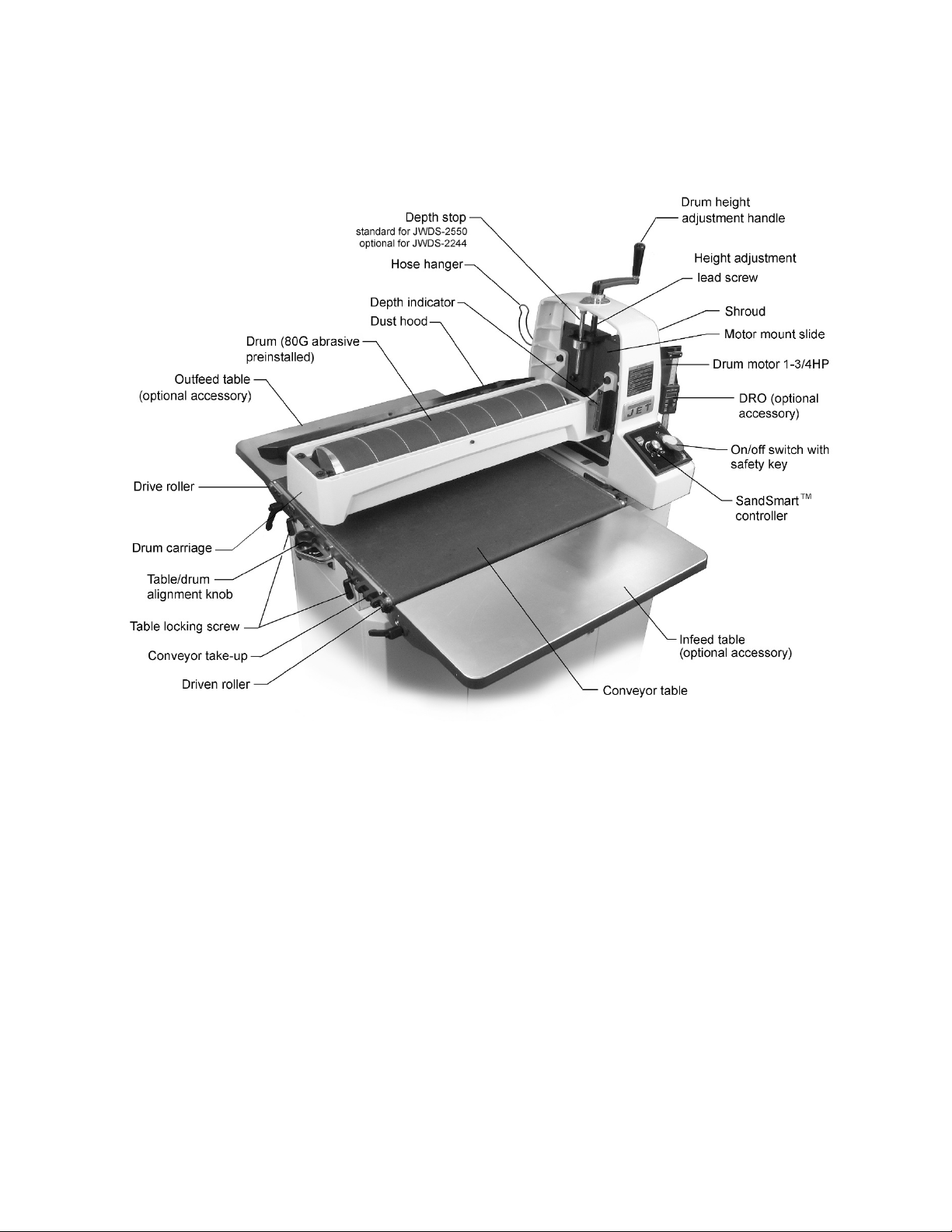
5.0 Features and Terminology
The illustration below shows the major components and features of the JWDS-2244/2550 Sanders. These are
referenced throughout the manual and will help to familiarize you with the operation and functions of the machine.
Figure 5-1: features
8
Page 9

Read and understand the entire
contents of this manual before attempting setup or operation! Failure to comply may cause
serious injury.
NOTE: Figures in this manual may show Sander
with stand, extension tables and/or depth stop
assembly. These are optional accessories
depending upon your model, and are purchased
separately.
6.0 Setup and assembly
Open boxes and check for shipping damage. Report
any damage immediately to your distributor and
shipping agent. Do not discard any shipping
material until the Drum Sander is assembled and
running properly.
Compare the contents of your boxes with the
following parts list to make sure all parts are intact.
Any missing parts should be reported to your
distributor. Read this instruction manual thoroughly
for assembly, maintenance and safety instructions.
6.1 Shipping contents
Drum Sander (Figure 6-1)
1 Sander with conveyor table – A
1 Height adjust handle – B
1 Hose hanger – C
2 Socket hd cap screw M6x12 – C
2 Flat washer 6mm – C
1 Operating Instructions and Parts Manual
1 Product registration card
OPTIONAL Infeed/Outfeed Tables (Figure 6-2)
2 Infeed/outfeed tables – D
1 Rear (short) fixed bracket – E
1 Front (long) fixed bracket – F
2 Left folding table brackets – G
2 Right folding table brackets – H
1 Hardware package, includes:
4 Locking handles – HP1
4 Disc washers – HP2
4 Oilite washers – HP3
16 Socket hd cap screws M8x16 – HP4
16 Flat washers M8 – HP5
4 Socket hd cap screws M6x20 – HP6
4 Eccentric cams – HP7
4 Flat washers M6 – HP8
2
6.2 Tools required for assembly
1
Figure 6-1: Sander contents (JWDS-2550 shown)
Figure 6-2: Infeed/Outfeed Tables (OPTIONAL)
5mm, 6mm hex (Allen) wrenches
Straight edge (such as straight steel bar or carefully
jointed board)
Additional tools may be required depending upon
other accessories purchased.
9
Page 10

Figure 6-3: Assembly of Sander and OPTIONAL Infeed/Outfeed Tables
6.3 Assembling stand
An open stand is provided standard with the JWDS2244 Sander. An open or closed stand is available
as an optional accessory (separate purchase) for
the JWDS-2550 Sander. Refer to the assembly
instructions that accompany the stand.
6.4 Mounting sander to stand
The closed stand (for JWDS-2550) is oriented so
that storage door is located at back of machine.
Front/back orientation is not important on the open
stand.
Use an assistant to help lift and
position sander atop stand.
1. Remove any screws holding sander to pallet,
and lift sander from crate.
2. Position sander atop stand so that six threaded
holes of base align with holes in stand rails.
Insert provided screws and washers and tighten
securely.
6.5 Handle and hose hanger
See Figure 6-3.
1. Install height adjustment handle (B) onto
spindle and tighten set screw.
2. Install hose hanger (C) with screws and
washers (C
1/C2
).
6.6 Folding infeed/outfeed tables
(OPTIONAL)
See Figure 6-3.
The sander must be bolted to the stand or a work
table when using these table extensions. Maximum
working load of each table is 35 pounds. Fasteners
are provided with the extension tables.
NOTE: If using the folding feature of the
infeed/outfeed tables, make sure your table or
bench allows for such vertical drop at front and back.
To install infeed table:
1. Install front (F) fixed bracket to threaded holes
in sander base with screws and washers
(HP4/5). Make sure bracket is oriented as
shown. Bracket must be flush against base.
NOTE: Long bracket mounts to front
(infeed); short bracket to rear (outfeed).
2. Tighten screws (HP4).
3. Install eccentric cam (HP8) with screw and
washer (HP6/7). Finger tighten only at this time.
4. Install left (G) and right (H) table brackets, using
handles and washers (HP1/2/3).
Note: Handle (HP1) is adjustable – pull up and
rotate on pin to more convenient position, then
release allowing it to settle back onto pin.
5. Place infeed table (D) onto table brackets and
secure with screws and washers (HP4/5).
Finger tighten only.
10
Page 11

Align infeed table with sander’s conveyor table as
follows.
See Figures 6-3 and 6-4.
6. Place a straight-edge at one side of conveyor
table under drum and extending out over infeed
table. See Figure 6-4. You may wish to lower
drum until it contacts the straight edge to hold it
in place.
7. Raise infeed table until it evenly contacts
straight edge. If needed, loosen four screws
(HP4) beneath table and adjust table to level.
Tighten screws.
8. Loosen screw (HP6) and rotate eccentric cam
(HP8) until it contacts lip of table bracket. Do
this on both sides of infeed table. This ensures
infeed table will remain level with conveyor
table each time it is returned to operating
position. Tighten screws (HP6).
9. Install outfeed table using identical procedure
as above.
TIP: It is often preferable to position infeed/ outfeed
tables slightly below conveyor table surface,
particularly if stock being sanded is bowed, warped
or otherwise inconsistent. Also, if stock slips on
conveyor, the tables may be positioned too high.
Figure 6-5 (hose and clamp not included)
6.8 Installing abrasives
Proper attachment of the abrasive strip to the drum
is critical to achieving top performance from your
drum sander.
An 80-grit, 3-inch wide abrasive is pre-installed on
drum. Optional pre-cut (“Ready-to-Wrap”) abrasives
of different grits are available; see sect. 14.0.
(TIP: If you are using an after-market abrasive, use
a new JET-supplied abrasive as a template to
quickly cut a new strip. Alternatively, a diagram is
supplied in Figure 6-6 showing trim dimensions.)
Figure 6-4: infeed table alignment
6.7 Dust collection
Dust collection is mandatory for a safe work
environment and extended abrasive life. The
JWDS-2244/2550 is equipped with a 4-inch dust
collection port. Secure a 4-inch dust collection hose
to the port with a hose clamp (Figure 6-5), and
connect to a high volume dust collector (minimum
550 CFM). Note: Dryer vent hose is not acceptable
for this purpose.
Keep hose clear of conveyor area by directing it over
the hose hanger at rear of sanding head.
A standard shop type canister (16 gal. or larger) can
be used for short periods of sanding time but
requires converting the hose size down to 2-1/2
inch. An adaptor (not included) is required.
Figure 6-6: abrasive trimming
(not applicable to Ready-to-Wrap strips)
To install abrasive strip:
1. Press fastener lever (Figure 6-7) on outboard
(left) end of drum, and insert tapered end of
abrasive through slit in fastener, as shown.
Align tapered edge of abrasive strip with left
edge of drum. Insert enough strip so that the
right edge aligns with the reference notch; this
will ensure the proper length of strip to be
secured at the opposite end of the drum.
Figure 6-7
11
Page 12

2. Release fastener lever to secure end of strip.
3. Begin wrapping abrasive around drum. The
tapered edge of strip end should follow as
closely as possible to edge of drum.
4. Continue wrapping abrasive in spiral fashion by
rotating drum with one hand and guiding strip
with the other. See Figure 6-8.
Successive windings of strip must not have any
overlap. They should be flush with previous
windings or with a slight gap between.
Figure 6-8
5. Press inboard take-up lever (Figure 6-9) and
insert trailing end of strip as far as it will go. If
necessary, trim tapered end of abrasive strip.
6. Release inboard take-up lever to secure strip.
All abrasive strips will stretch over time as they are
used, and may stretch enough to allow the take-up
lever to reach its lowest position so that it cannot
maintain tension on the strip. If this occurs, follow
the above procedures to reset the take-up lever.
Figure 6-9
7.0 Electrical connections
All electrical connections must
be done by a qualified electrician in compliance
with all local codes and ordinances. Failure to
comply may result in serious injury.
The JWDS-2244 and JWDS-2550 Sanders are
rated for single phase, 115-volt power only. The
sander comes with a plug designed for use on a
circuit with a grounded outlet that looks like the one
pictured in Figure 7-1.
Before connecting to power source, be sure switch
is in off position.
It is recommended that the sander be connected to
a dedicated 20 amp circuit with circuit breaker or
fuse. If connected to a circuit protected by fuses, use
time delay fuse marked “D”. Local codes take
precedence over recommendations.
7.1 GROUNDING INSTRUCTIONS
This machine must be grounded. In the event of a
malfunction or breakdown, grounding provides a
path of least resistance for electric current to reduce
the risk of electric shock. This tool is equipped with
an electric cord having an equipment-grounding
conductor and a grounding plug. The plug must be
plugged into a matching outlet that is properly
installed and grounded in accordance with all local
codes and ordinances.
Do not modify the plug provided - if it will not fit the
outlet, have the proper outlet installed by a qualified
electrician.
Improper connection of the equipment-grounding
conductor can result in a risk of electric shock. The
conductor with insulation having an outer surface
that is green with or without yellow stripes is the
equipment-grounding conductor.
If repair or replacement of the electric cord or plug
is necessary, do not connect the equipmentgrounding conductor to a live terminal.
Check with a qualified
electrician or service personnel if the grounding
instructions are not completely understood, or if
in doubt as to whether the tool is properly
grounded. Failure to comply may cause serious
or fatal injury.
Use only 3-wire extension cords that have 3-prong
grounding plugs and 3-pole receptacles that accept
the tool's plug.
Repair or replace damaged or worn cord
immediately.
This tool is intended for use on a circuit that has an
outlet that looks like the one illustrated in Figure 7-
1. An adapter, shown in Figure 7-2, may be used to
connect this plug to a 2-pole receptacle as shown in
Figure 7-2 if a properly grounded outlet is not
available. The temporary adapter should be used
only until a properly grounded outlet can be installed
by a qualified electrician. The green-colored rigid
ear, lug, and the like, extending from the adapter
must be connected to a permanent ground such as
a properly grounded outlet box.
In Canada, the use of a temporary adaptor is not
permitted by the Canadian Electrical Code, C22.1.
12
Page 13

Figure 7-1
Figure 7-2
7.2 Extension cords
The use of extension cords is discouraged; try to
position machines near the power source. If an
extension cord is necessary, make sure it is in good
condition. When using an extension cord, be sure to
use one heavy enough to carry the current your
product will draw. An undersized cord will cause a
drop in line voltage resulting in loss of power and
overheating. Table 2 shows correct size to use
depending on cord length and nameplate ampere
rating. If in doubt, use the next heavier gauge. The
smaller the gauge number, the heavier the cord.
Recommended Gauges (AWG) of Extension Cords
Extension Cord Length *
25
50
75
100
150
200
Amps
< 5 16 16 16 14 12 12
5 to 8 16 16 14 12 10 NR
8 to 12 14 14 12 10 NR NR
12 to 15 12 12 10 10 NR NR
15 to 20 10 10 10 NR NR NR
21 to 30 10 NR NR NR NR NR
*basedonlimitingthelinevoltagedropto5Vat150%oftherated
amperes.NR:NotRecommended.
feet
feet
Table 2
feet
feet
feet
feet
8.0 Adjustments
8.1 Drum Height Control
Drum height and depth of cut are controlled by
height adjustment handle (B, Figure 6-3). Rotating
handle clockwise lowers drum, counterclockwise
raises it. One revolution of handle will move drum
approximately 1/16” (or 1/4 turn = approx. 1/64”), as
shown on label below handle.
8.2 Depth scale
The depth scale indicates distance between bottom
of sanding drum and top of conveyor belt.
Adjustment is performed by “zeroing” the scale.
1. Unplug sander from power source.
2. With an abrasive strip on drum, lower drum to
where it just contacts top of conveyor belt. Note:
Make sure drum – not just tension rollers –
contacts conveyor belt.
3. At this drum position, the depth scale pointer
should align with zero mark on scale. If it does
not, loosen two screws on scale and adjust
scale until zero aligns with the pointer.
4. Retighten screws.
Depending on desired accuracy, you may need to
repeat this process when installing different
abrasive grits.
8.3 Depth stop assembly
(OPTIONAL)
NOTE: The depth stop assembly is optional for
JWDS-2244, but included with JWDS-2550.
The depth stop nut (A, Figure 1) provides a hard
stop at final sanding depth. It ensures that the
operator will not sand too deeply when he/she
wishes to make multiple pieces the same final
thickness.
1. Rotate handle to position drum at final sanding
depth according to scale. (Figure 8-1 shows
7/8-inch final depth as example).
2. Press button on stop nut to slide nut into general
position, then rotate nut until it firmly contacts
bottom of plate (B).
CAUTION: The stop nut is designed to be used
below the plate to allow full support when nut
contacts plate. Using it above the plate may
cause deflection as nut pushes into it.
3. Raise drum and perform sanding operation.
Depending on the workpiece, multiple passes
may be needed until final depth is reached and
stop nut is contacted.
If stop assembly will not be used, loosen left screw
(C) and rotate plate (B) out of the way (see inset).
This allows free drum movement.
13
Page 14

Excessive belt tension can result in bent rollers,
bent brackets, and/or premature wearing of
bushings or conveyor belt.
Figure 8-3: belt take-up screw
Figure 8-1
8.4 Infeed/Outfeed Table Adjustment
(OPTIONAL)
The optional tables can be swung down to allow
easier access for abrasive wrapping or other
adjustments.
Loosen handles on each side, slide table away from
machine and then down. See Figure 8-2.
Figure 8-2
8.5 Conveyor belt tension/tracking
Conveyor belt tension adjustment may be
necessary during the break-in period to compensate
for belt stretching.
8.5.1 Belt tension adjustment
1. Adjust take-up screw (Figure 8-3) with 5mm hex
wrench. Do this on both sides of conveyor to
obtain approximately equal tension on both
sides of conveyor belt when taut.
NOTE: Insufficient belt tension will cause
slippage of conveyor belt on drive roller during
sanding operation. The conveyor belt is too
loose if it can be stopped by hand pressure
applied directly to top of moving conveyor belt.
A belt tracks correctly when it moves centrally on the
conveyor rollers without drifting to either side.
Tracking adjustments are made while conveyor belt
is running.
1. Make sure proper belt tension has been
achieved (see sect. 8.5.1).
2. Turn on conveyor and set to maximum speed.
Watch for tendency of conveyor belt to drift to
one side of conveyor. If it drifts, tighten or
loosen take-up screw on either side (Figure 8-
3).
Note: Adjust take-up screw only 1/4 turn at a time.
Allow time for belt to react to adjustments before
proceeding further.
Avoid over-adjusting, as this may affect belt tension.
If tension is affected, it may become necessary to
use both take-up screws to accomplish tensioning
and tracking.
8.5.3 Trackers
8.5.2 Belt tracking adjustment
The sander comes equipped with “Trackers”,
ceramic guides that reduce the amount of
adjustments needed to keep conveyor belt tracked
(centered) on conveyor table. These guides have a
magnetic backing to keep them in place. If a Tracker
wears through, it can be reversed by turning it over.
See sect. 11.0 Tracker Kit for more information
about re-setting trackers.
8.6 Inspecting drum alignment
The sanding drum must be parallel to conveyor table
for proper machine operation. The sanding drum
comes pre-aligned from the manufacturer. If a
problem with drum alignment should occur, follow
the instructions below.
First, inspect the alignment with a gauge of some
kind. The following procedure uses a steel straightedge as a gauge.
1. Unplug sander from power source.
14
Page 15

2. Open dust cover and remove abrasive strip
from drum.
3. Insert gauge (A, Figure 8-4) between drum and
conveyor table at outboard side.
Figure 8-4: drum alignment
4. With dust cover open, lower sanding drum while
slowly rotating drum by hand, until drum lightly
contacts gauge. NOTE: Make sure drum
contacts gauge, not just the tension rollers.
Make a note of the measurement on the
sander’s depth scale.
5. Remove gauge and place under drum at
inboard side.
6. If drum does not contact gauge equally on both
ends of drum, alignment is needed.
To align conveyor table with drum:
7. Loosen both table locks (B, Figure 8-4)
lower table at outboard end slightly by turning
knob (C).
4. Repeat this process until the ridge is eliminated
and entire board is sanded.
Note: When sanding narrow stock (less than 16”),
return conveyor table to parallel position. Turn knob
opposite direction until lock nut (D, Figure 8-4) is
contacted. The lock nut provides a positive stop for
table parallelism.
8.7 Tension roller adjustment
The infeed and outfeed rollers are tensioned to
provide downward pressure on the workpiece to
prevent slippage on the feed conveyor. Tension
rollers have been set by the manufacturer, but
should be inspected and may require adjustment as
the sander receives use.
Improperly adjusted tension
rollers (i.e. those set too high, rendering them
non-functional) could allow kickback of pieces
being sanded.
You can increase or decrease tension roller
pressure by turning the screws on the tension roller
brackets (Figure 8-5).
Loosen both table locks
before adjusting drum alignment. Failure to
comply may cause damage to table.
8. Turn knob (C) to raise or lower outboard end of
table. Follow directional marks on label: (+) to
raise, (-) to lower.
9. Tighten table locks (B).
8.6.1 Fine-tuning drum alignment
Note: This is an operational test for sanding boards
wider than the drum. Perform this procedure only
after you have become familiar with sander
operation.
When sanding boards wider than the drum, table
alignment is critical and table must be adjusted
exactly level to slightly lower on the outboard end.
This will prevent any ridges from developing in the
stock. Always check this on a piece of scrap wood,
as follows, before sanding the workpiece.
1. Run a piece of scrap wood approximately 6”
wide by 30” to 40” long through the sander
sideways so that end of board extends past
outboard side of drum.
2. Without changing drum height, rotate board
180° and sand the same side.
3. If a ridge is visible where the drum overlaps,
loosen both table locks (B, Figure 8-3) and
Figure 8-5: tension adjustment screws
Too much tension roller pressure can result in a
“snipe” mark, which is a visible line located near the
end of the board and running across its width.
If snipe occurs on the leading end of board, adjust
outfeed tension roller. If the snipe occurs on trailing
end of board, adjust infeed tension roller.
15
Page 16

9.0 Operations
Before using the drum sander, review the previous
sections on initial set-up and adjustment. Before
operating, make sure an abrasive strip is mounted
and a proper dust collection system is connected.
9.1 Basic Operating Procedure
1. Establish depth of cut.
2. Start dust collection system.
3. Start sanding drum.
4. Start conveyor and select feed rate.
5. Feed stock through machine.
To feed stock through the sander, rest and hold
board to be sanded on conveyor belt, allowing
conveyor belt to carry board into drum. Once stock
is halfway through, reposition yourself to outfeed
side of machine to receive and control board as it
exits.
and familiarity with the machine before doing finish
work.
A combination of several variables will determine
proper depth of cut to use, including the following:
1. Abrasive type and grit size.
2. Width of piece being processed.
3. Hardness of piece.
4. Feed rate of conveyor belt.
NOTE: The use of a carrier or backer board (not
provided), is recommended for cuts 1/16” or less.
This is a flat board, usually of wood or MDF, slightly
larger than the workpiece and of even thickness,
placed beneath the workpiece as it is fed through
the sander. The workpiece may be attached to the
carrier with rubber cement, carpenter’s tape or
some other easily removable adhesive. However,
some operators use a rubber or textured surface on
the carrier to help stabilize the workpiece by simple
friction.
Board will be forced down
against conveyor table as it begins feeding,
causing pinching hazard. Keep fingers away.
Do not open drum hood until
drum comes to a complete stop.
9.2 Switch safety key
To prevent unauthorized use of sander, turn off
switch and pull out safety key (Figure 9-1). Store key
in a safe place. Key must be reinserted to start
sander.
Figure 9-1: safety key
9.3 Setting depth of cut
Adjusting the drum sander for proper contact
between abrasive and stock determines the depth
of cut, which is controlled by the height adjustment
handle.
It may take experimentation to determine proper
depth of cut, given the variables of abrasive grit,
type of wood, and feed rate. For best results, use
scrap wood to practice sanding and to develop skill
9.4 Establishing drum height
A good rule of thumb when sanding with grits finer
than 80:
1. To establish drum height, position stock under
the drum. Do NOT start drum.
2. Lower drum to the stock thickness, making sure
drum can still be rotated by hand while just
contacting stock.
Do not start drum while in
contact with stock.
3. Without changing drum height, turn on
conveyor and run the stock out from under the
drum. Start sanding drum and sand stock at that
same position.
4. With the drum operating, feed stock under the
drum from the infeed side and against the
rotation of the drum. Always maintain control of
the stock to avoid kickback and/or slippage.
NOTE: If motor heats up during operation,
depth of cut may be too great for size of grit
and/or feed rate may be too fast.
For sanding with grits coarser than 80, you can
lower the drum slightly.
Always maintain control of stock. Through practice
you will learn the proper depth of cut considering the
variables above.
9.5 Selecting SandSmart™ feed rates
A faster feed rate allows faster sanding but fewer
revolutions of the drum per inch of sanding. A slower
feed rate provides more revolutions of the drum per
inch of sanding to allow a greater depth of cut and
smooth sanding.
Begin experimenting with the feed rate set at about
40% to 50% of maximum. The best feed rate will
16
Page 17

depend on a number of factors, including type of
stock, grit and depth of cut used, and whether the
stock is fed directly in line with the conveyor table or
at an angle. If the drum motor is lugging down, if
conveyor belt is slipping, or if you observe a ripple
effect on the stock, slow the feed rate. If the finish is
smooth and the machine is not overworking, you
can experiment using a faster feed rate.
The SandSmart controller continuously monitors the
load on the drum motor, and automatically regulates
the speed of the conveyor motor to maintain the
highest feed rate without overload.
When the red indicator light (see B, Figure 9-1)
comes on, the SandSmart control has detected too
great a depth of cut and/or too fast a feed rate.
If the load on the drum motor increases, the
SandSmart control will decrease the conveyor feed
rate and will stop the conveyor under extreme
conditions. If the load on the drum decreases,
SandSmart will increase the feed rate but will not
increase it faster than the manual setting on the
speed adjustment label.
The best and most consistent finish will be achieved
if the conveyor does not change speed during
operation.
This change in conveyor speed may affect the finish
surface. If the finish is affected, make another
sanding pass without changing any settings. If the
finish is still affected, make adjustments by slowing
the conveyor and/or decreasing the depth of cut and
run the stock through again.
Also try a faster feed rate or less depth of cut if the
stock you are working begins to show burn marks.
With cherry, hard maple or other hardwoods, using
a shallower depth of cut and a faster feed rate will
help minimize burn marks. Slightly angling the stock
as it is fed into the machine will also help prevent
burning the stock.
Because of the wide range of variables, it is
important to experiment with your specific
conditions and make adjustments to achieve the
optimum feed rate. If problems occur, first check and
adjust the feed rate, referring to the
“Troubleshooting” section in this manual.
9.6 Maximum performance tips
The versatility designed into the JWDS-series drum
sander allows it to be used for a variety of tasks that
will boost return on your investment. For example, it
will speed up fine sanding work often done with
slower, dust-generating hand sanders, and will
achieve fine thickness adjustments not possible on
some sanders. It can be used to surface figured
woods – bird’s eye or curly maple, for example –
which can be damaged if fed through a planer.
Learning how to use its adjustments and controls
will allow you to fine-tune the machine for maximum
results. The best results come from experimenting
with different abrasive grits and machine
adjustments to fit the job at hand. Following is a list
of useful tips which can help you improve
performance of your sander.
9.6.1 Dust collection
When connecting dust collectors, remember that
straight pipe will not restrict airflow as much as
flexible tubing. Y’s and elbows will restrict airflow
less than T’s. Also, a hose smaller than 2-1/2”
diameter should not be used.
9.6.2 Multiple-piece sanding runs
When abrasive planing (or thickness sanding) a run
of similar pieces that you want to have the same
thickness, it is best to determine the thickness of the
thinnest piece and process all pieces to that same
thickness in one session. Be aware that the sander
will remove cups and crowns in the workpiece;
consider this when measuring and processing stock
to the same thickness.
9.6.3 Simultaneous multiple pieces
When sanding multiple pieces simultaneously,
make sure to stagger (step) the pieces across the
width of the conveyor belt. This provides better
contact with the tension rollers. Try to process only
multiple pieces of similar thickness.
If there is a significant thickness difference, the
thinner pieces can slip on the conveyor belt if they
do not contact the tension rollers. Also note that
pieces thicker than 3/4” should be longer than the
minimum normally recommended to prevent tipping
of the stock.
9.6.4 Edge sanding
When edge sanding, the sander will mimic the
opposite edge of the stock which is lying on the
conveyor belt. Because of this, it is important for the
stock edge to have been ripped at the proper angle
to the face before the sanding process. When edge
sanding stock that is less than 3/4” wide or more
than 2” high, it is good procedure to stack and clamp
several pieces together to prevent them from
slipping or tipping on the conveyor belt.
9.6.5 Sanding imperfect stock
When sanding stock with a cup or crown, place the
crown up. This will stabilize the stock to help prevent
tipping or rocking during sanding. After the crown
has been removed and the top is flat, turn the stock
over and sand the opposite side. To avoid personal
injury, take special care when sanding stock that is
twisted, bowed, or otherwise varies in thickness
from end to end. If possible, support such stock as
it is being sanded to keep it from slipping or tipping.
Use extra roller stands, help from another person,
or hand pressure on the stock, to minimize
potentially hazardous situations.
17
Page 18

9.6.6 Face frames and raised panel
doors
It is very important to have the proper abrasive
contact when doing this type of sanding. If the
machine is set to take an excessive depth of cut, the
result can be a gouge or dip as the drum goes from
sanding the rails at full width to sanding just a few
inches of width on the stiles. To prevent this make
sure, when using abrasives finer than 80 grit, that
the drum is in contact with the wood but can still be
spun by hand. If there is room, angling the stock on
the conveyor belt can also help.
Slowing the conveyor feed when coming to a rail in
the stock can help prevent a dip or gouge. This
allows the abrasive to work the wider width with less
effort, and to achieve better consistency of the
finished surface.
9.6.7 Stock feeding angle
Some pieces, because of their dimensions, will
need to be fed into the machine at a 90° angle
(perpendicular to drum). However, even a slight
offset angle of stock will provide for more effective
stock removal. The optimum feeding angle for stock
removal is about 60°.
Angling the workpiece for stock removal provides
other advantages, such as less loading of certain
areas of the drum due to glue lines or mineral
streaks in the stock, more even wear of abrasive
strips, potentially faster feed rates, and lighter loads
on the motor. Note that to get the best final finish,
however, the stock should be fed through the
machine so it will be sanded in line with the grain of
the wood on the final one or two passes.
10.0 User-maintenance
Before doing maintenance on
the machine, disconnect it from the electrical
supply (pull out the plug), unless indicated
otherwise. Failure to comply may cause serious
injury.
Lubricate conveyor bushings as needed, and
check for wear.
Lubricate elevating leadscrew (A, Figure 10-1)
as needed.
Clean sawdust from abrasive strip and brush
dust from conveyor belt.
Keep slide areas clean (B, Figure 10-1).
Blow dust from motors and switches.
Blow dust from inside of sanding drum, which
may cause vibration or offset the center of
balance. (Leave your dust collector on when
cleaning dust from the drums.)
Check all set screws for tightness on parts such
as bearings, conveyor table, and couplings.
Figure 10-1
10.2 Drum maintenance
The drum should not require removal from the
machine under normal circumstances. Should
maintenance ever become necessary, the drum has
been designed for easy removal and replacement.
1. Disconnect sander from power source/unplug.
2. Remove four socket head screws (C, Figure 10-
2).
3. Carefully lift out drum with coupling (D)
attached.
10.1 Cleaning and lubrication
For best results, make cleaning the sander a regular
shop procedure. Allowing excess build-up of dust
and debris can adversely affect performance
through loading of the abrasives, slippage on the
conveyor table, and/or the accumulation of material
inside the drums which can throw off the center of
balance.
NOTE: Bearings are pre-sealed and require no
lubrication.
Brush the conveyor belt after cleaning
operations. If not cleaned, the conveyor belt
could allow stock to slip during sanding
operations.
18
Figure 10-2: drum removal
Page 19

10.3 Conveyor belt replacement
10.4 Commutator brush inspection
1. Disconnect sander from power source/unplug.
2. Raise drum to highest position.
3. Remove infeed/outfeed tables, if installed.
4. Turn take-up screws (see Figure 8-3) on both
sides of conveyor to relieve belt tension, and
slide the driven roller fully inward.
5. Remove two (2) screws at inboard side which
attach conveyor table to base.
6. Remove two (2) screws that attach conveyor
table to drum alignment bracket (E, Figure 10-
3).
7. Loosen two table locks (F, Figure 10-3).
8. Lift up conveyor table and remove it from
machine. Avoid tearing the belt on any edges
underneath the conveyor table. Do not allow the
Trackers to drop, as they may break.
9. Set conveyor on motor side and slide conveyor
belt off end of conveyor table.
10. Install new belt along with trackers (see sect.
11.0), and re-install conveyor table. Tension
and track the new belt.
Figure 10-3
Note: If conveyor belt continually tracks to one side
of the machine, reversing the belt on the conveyor
table may remedy the problem. To make sure the
conveyor table is not twisted, place a level on the
conveyor table. Level the machine if needed. If there
is still a problem, proceed with the steps below:
Step 1: Check conveyor drive roller and driven roller
to make sure they are parallel to surface of conveyor
table. To do this, first center conveyor belt on the
conveyor table. Then lay a straight-edge on the
exposed edge of conveyor table on left (outboard)
side, extending it over the roller. Note distance
between roller and straightedge.
Step 2: Now repeat Step 1 on right (inboard) side of
conveyor. Compare the measurements from side to
side. If they are not equal, loosen one of the
brackets that hold the roller in place. Tip this bracket
until distance between roller and straight-edge are
equal from side to side, then tighten bracket.
To maintain motor efficiency, inspect the two carbon
brushes every two months, or more frequently if
sander is heavily used. Stalling or loss of power may
be a symptom of worn carbon brushes. If one brush
is worn out, replace both at the same time.
Continued use of damaged or
worn brushes may result in damage to motor
armature.
1. Disconnect sander from power source/unplug.
2. Unscrew and remove cap with flat blade
screwdriver. See Figure 10-4.
3. Gently pry up an edge of the brass clip, until the
spring causes it to disengage from hole. (Notice
orientation of brush as you remove it; it should
be inserted in the same manner; curvature of
brush will match curvature of motor.)
4. Pull out brush and inspect. Brush should be
replaced if any of the following are discovered:
Brush has worn to about 1/2-inch long.
Signs of crumbling, burning or breaking.
End of brush is rough or pitted.
Abnormal coloration of spring
Broken lead in spring
Collapsed spring
5. Install new brush (or reinstall current brush) and
gently press it all the way into hole until the
brass clip is secured.
6. Install cap.
7. Repeat for other brush.
NOTE: It is recommended that sander be run
without load for several minutes to seat new
brushes.
Figure 10-4
10.5 Additional servicing
Any additional servicing should be performed by an
authorized service technician.
19
Page 20

11.0 Tracker kit
Stock No.: PM2244-213
Trackers dramatically reduce tracking adjustments
of conveyor belts. They are already installed on your
sander. The following information is for resetting or
replacing your trackers, should that become
necessary.
1. Disconnect power to sander.
2. Raise drum as high as it will go.
3. Turn both conveyor take-up screws to relieve
conveyor belt tension and slide driven roller fully
inward.
4. Remove the 2 bolts and loosen 2 wing screws
holding conveyor table to sander base.
5. Lift conveyor table and slide it out of sander.
Turn conveyor table upside down. Be careful
not to damage conveyor belt.
6. On the underside of the conveyor table, there
are U-channels welded to the table. The
Tracker is positioned on the inside of the first Uchannel on the infeed side of sander (Figure 11-
1). The back of tracker is magnetized and will
stick to side wall of conveyor table. Do not install
tracker if edge of conveyor belt is damaged or
torn.
7. With first tracker installed, slide conveyor belt
into bottom slot of tracker. Note: When installed
properly, only bottom lip of tracker will be
visible. The top slot can be used if bottom slot
wears out.
8. Install second tracker opposite the first. Use
both trackers unless the second one does not
fit in conveyor or unless conveyor belt is
damaged.
9. Turn conveyor table right-side up and reposition
it onto sander. Re-attach three mounting
screws and tighten. Caution: Be careful not to
knock tracker(s) out of conveyor table when
turning conveyor over. Trackers may break if
allowed to fall.
10. Make sure all switches are off. Connect power
to sander and plug in motor.
11. Tension conveyor belt using take-up screws. If
both trackers are installed, it is very important to
have equal tension on both sides of conveyor
belt. Turn take-up screws on both sides until
equal tension is obtained.
12. To check tension, turn on conveyor full speed
and place both hands on conveyor. If conveyor
belt can be stopped, continue tensioning until
conveyor belt cannot be stopped by both hands
on the belt while conveyor is operating at full
speed.
13. Make sure conveyor belt runs smoothly inside
tracker slot and that the magnet is holding the
tracker in position.
14. Continue to watch tracking of conveyor and
adjust only if necessary, making sure to keep
equal tension on conveyor belt at all times and
not allowing conveyor belt to buckle under
conveyor table.
Figure 11-1: Underside of conveyor shown
20
Page 21

12.0 Abrasives
The abrasive material you choose will have a
substantial effect on the performance of your
sander. Variations in paper type, weight, coating
and durability all contribute to achieving your
desired finish.
JET Abrasives are available in Ready-To-Wrap
pre-cut lengths or in the convenient Ready-To-Cut
pre-marked box. Your JET dealer can recommend
the best choice for your application.
12.1 Selecting drum abrasives
It is important to select the proper grit of abrasive for
the type of sanding being performed to achieve
maximum results. As with any sanding operation,
first begin sanding with a coarser grit, depending
upon the roughness of the stock or the amount of
stock to be removed. Then progressively work
toward finer grits. The chart below shows the
general uses for the various grits.
The amount of stock to be removed is a major
consideration when choosing the grit grade with
which to begin. Grits 24, 36, 50 and 60 are primarily
designed for stock removal. Grits 24 and 36 will
remove the most material in one pass, whether you
are doing abrasive planing, cleaning up glued
panels, or flattening stock. Grits from 100 through
220 are primarily finishing grits designed to remove
the scratch pattern from the previous grit used. For
best results, never skip more than one grit grade
when progressing through a sanding sequence.
For fine work, such as furniture, try not to skip any
grit grades during the sanding process.
In general, premium quality abrasives will produce a
better finish with a less noticeable scratch pattern.
TM
Note: Grits that are too fine can sometimes burnish
the wood and leave a glossy surface which will not
accept stains evenly. This will vary by type of wood.
Oak, for example, is susceptible to burnishing
because of its open pores.
12.2 Cleaning abrasive strips
Regularly clean the abrasive strip on the drum with
commercially available cleaning sticks, following the
manufacturer’s directions. When cleaning, also
brush the stick crumbs from the drum while it is still
rotating.
In some cases, heavily loaded areas can be
removed with Plexiglas held on edge over the
rotating drum.
Always wear eye protection
while performing sandpaper cleaning, and take
all precautions to avoid any contact of hands or
clothing with the rotating drum.
Cloth-backed abrasives can be cleaned by soaking
in paint thinner or mineral spirits for 20 minutes to
one hour, then using a brush to remove any buildup. Dry the abrasive strips completely before using.
Any used solvents should be discarded in
compliance with environmental regulations.
12.3 Increasing abrasive life
Abrasive life can be increased not only by cleaning,
but by removing the abrasive strip from the drum
and reversing it. To do this, remove the strip and use
what was the trailing end as the starting end on the
left (outboard) side of the drum. Reversing the strip
will provide a fresh set of cutting edges on the
abrasive.
12.4 Abrasive selection guide
Grit Common Application
24 Abrasive planing, surfacing rough-sawn boards, maximum stock removal, glue removal.
36 Abrasive planing, surfacing rough-sawn boards, maximum stock removal, glue removal.
50 Surfacing and dimensioning boards, truing warped boards
60 Surfacing and dimensioning boards, truing warped boards.
80 Light dimensioning, removal of planer ripples.
100 Light surfacing.
120 Light surfacing, minimal stock removal.
150 Finish sanding, minimal stock removal.
180 Finish sanding only, not for stock removal.
220 Finish sanding only, not for stock removal.
Table 2
21
Page 22

13.0 Troubleshooting JWDS-2244,-2550 Drum Sanders
Symptom Possible Cause Correction *
Drum motor won’t start
when switch is activated.
Drum motor will not start:
fuses blow or circuit
breakers trip.
Drum motor overheats. Air circulation through motor restricted. Clean motor fan with compressed air to
Drum motor stalls,
resulting in blown fuses
or tripped circuit.
Loud, repetitive noise or
vibration coming from
machine.
No incoming current. Check connections at plug or circuit panel.
Safety key missing from switch. Install safety key.
Low voltage. Check power line for proper voltage.
Open circuit in motor or loose
connection.
Switch malfunction. Replace switch.
Short circuit in line cord or plug. Inspect cord or plug for damaged insulation
Short circuit in motor or loose
connections.
Incorrect fuse or circuit breaker in
power line.
Motor overloaded (SandSmart not
functioning properly).
Short circuit in motor or loose
connections.
Low voltage. Correct low voltage conditions.
Incorrect fuse or circuit breaker in
power line.
Fasteners loose. Inspect fasteners and tighten where needed.
Motor fan is hitting cover. Tighten fan or shim fan cover.
Machine not level. Place sander on level floor; shim if needed.
Inspect all lead connections on motor for
loose or open connections.
and shorted wires.
Inspect all connections on motor for loose or
shorted terminals or worn insulation.
Install correct fuse or circuit breaker.
restore normal air circulation.
Have controls inspected and repaired.
Inspect connections on motor for loose or
shorted terminals or worn insulation.
Install correct fuse or circuit breaker.
Conveyor motor stalls. Excessive depth of cut. Reduce depth of cut; use coarser grit;
reduce feed rate.
Conveyor belt does not
move.
Conveyor rollers run
intermittently.
Conveyor belt slips on
drive roller.
Abrasive strip comes off
drum.
Abrasive strip is loose. Strip caught on inside edge of slot, or
Abrasive loads up
prematurely.
Line or groove in stock. Inconsistent feed rate. Do not stop or change the feed rate while
Snipe marks. Improper tension on rollers. Re-tension rollers.
Shaft coupler is loose or unattached. Adjust shaft coupler.
Shaft coupling is loose. Align the shaft flats of the gear motor and
the drive roller and tighten the shaft-coupling
setscrews.
Improper conveyor belt tension. Adjust belt tension.
Excessive depth of cut and/or feed
rate.
Slack in abrasive strip on drum. Remove slack in strip.
Abrasive improperly wrapped. Read the section on installing abrasives, and
on inboard side of drum.
Strip not cut properly. Re-cut and re-install the abrasive strip.
Excessive depth of cut. Reduce depth of cut.
Excessive feed rate. Reduce feed rate.
Inadequate dust collection. Increase airflow at dust port.
Inadequate abrasive. Use an open-coat abrasive.
Reduce depth of cut and/or feed rate.
rewrap.
Re-adjust the strip end in the slot and/or trim
the abrasive edge.
feeding stock.
22
Page 23

Symptom Possible Cause Correction *
Sander burns wood. Abrasive strip is overlapped. Re-wrap abrasive strip.
Abrasive is loaded. Clean abrasive.
Depth of cut excessive for fine grit. Use coarser grit or reduce depth of cut.
Feed rate too slow. Increase feed rate.
Abrasive is worn. Replace abrasive.
Board slips on conveyor
belt.
Ripples in sanded
surface.
A. Non-uniformly spaced
ripples.
B. Uniformly spaced
ripples.
Wood is gouged. Stock slipping on conveyor. Correct depth of cut or roller tension.
* WARNING: Some corrections may require a qualified electrician.
Tension rollers too high. Lower tension rollers.
(optional) extension tables too high. Adjust tables.
Excessive feed rate. Reduce feed rate.
Dirty or worn conveyor belt. Replace conveyor belt.
A. Uneven feed rate. Conveyor belt slipping (see above)
Board slips on conveyor belt (see above).
Conveyor motor stalls (see above).
B. Conveyor table flexing or vibration. Reduce depth of cut and/or feed rate. Check
for loose bolts, loose shaft coupling set
screws, or out-of-balance drum.
Work piece not properly supported. Add work supports for long work pieces.
Table 3
23
Page 24

14.0 Optional accessories
For JWDS-2244:
723541 Folding Infeed/Outfeed Tables for JWDS-2244
723552 Digital Read Out
723553 Depth Stop Assembly
98-0130 Locking Casters for Open Stand, set of 4
The following abrasives are available only for model JWDS-2244
(Abrasive strips are 3” wide, cloth backed, aluminum oxide, resin bond, open coat.)
60-2036 Ready-To-Wrap
60-2060 Ready-To-Wrap
60-2080 Ready-To-Wrap
60-2100 Ready-To-Wrap
60-2120 Ready-To-Wrap
60-2150 Ready-To-Wrap
60-2180 Ready-To-Wrap
60-2220 Ready-To-Wrap
60-9036 Premium Ready-To-Cut
60-9060 Premium Ready-To-Cut
60-9080 Premium Ready-To-Cut
60-9100 Premium Ready-To-Cut
60-9120 Premium Ready-To-Cut
60-9150 Premium Ready-To-Cut
60-9180 Premium Ready-To-Cut
60-9220 Premium Ready-To-Cut
For JWDS-2550:
723550OS Open Stand for JWDS-2550
723544CS Closed Stand for JWDS-2550
723551 Folding Infeed/Outfeed Tables for JWDS-2550
723552 Digital Read Out
98-0130 Locking Casters for Open Stand, set of 4
The following abrasives are available only for model JWDS-2550
(Abrasive strips are 3” wide, cloth backed, aluminum oxide, resin bond, open coat.)
60-25036 Ready-To-Wrap
60-25060 Ready-To-Wrap
60-25080 Ready-To-Wrap
60-25100 Ready-To-Wrap
60-25120 Ready-To-Wrap
60-25150 Ready-To-Wrap
60-25180 Ready-To-Wrap
60-25220 Ready-To-Wrap
TM
Abrasive Strip, 36 Grit (3 wraps)
TM
Abrasive Strip, 60 Grit (3 wraps)
TM
Abrasive Strip, 80 Grit (3 wraps)
TM
Abrasive Strip, 100 Grit (3 wraps)
TM
Abrasive Strip, 120 Grit (3 wraps)
TM
Abrasive Strip, 150 Grit (3 wraps)
TM
Abrasive Strip, 180 Grit (3 wraps)
TM
Abrasive Strip, 220 Grit (3 wraps)
TM
Abrasive Strip, 36 Grit (10 wraps)
TM
Abrasive Strip, 60 Grit (14 wraps)
TM
Abrasive Strip, 80 Grit (14 wraps)
TM
Abrasive Strip, 100 Grit (14 wraps)
TM
Abrasive Strip, 120 Grit (14 wraps)
TM
Abrasive Strip, 150 Grit (14 wraps)
TM
Abrasive Strip, 180 Grit (14 wraps)
TM
Abrasive Strip, 220 Grit (14 wraps)
TM
Abrasive Strip, 36 Grit, (3 wraps in a box)
TM
Abrasive Strip, 60 Grit, (3 wraps in a box)
TM
Abrasive Strip, 80 Grit, (3 wraps in a box)
TM
Abrasive Strip, 100 Grit, (3 wraps in a box)
TM
Abrasive Strip, 120 Grit, (3 wraps in a box)
TM
Abrasive Strip, 150 Grit, (3 wraps in a box)
TM
Abrasive Strip, 180 Grit, (3 wraps in a box)
TM
Abrasive Strip, 220 Grit, (3 wraps in a box)
15.0 Replacement Parts
Replacement parts are listed on the following pages. To order parts or reach our service department, call 1-800274-6848 Monday through Friday, 8:00 a.m. to 5:00 p.m. CST. Having the Model Number and Serial Number of
your machine available when you call will allow us to serve you quickly and accurately.
Non-proprietary parts, such as fasteners, can be found at local hardware stores, or may be ordered from JET.
Some parts are shown for reference only, and may not be available individually.
24
Page 25

15.1.1 JWDS-2244/-2550 Head Assembly – Exploded View
98
G
51
99
103
102
104
89
91
92
93
F
94
97
99
95
100
101
96
88
54
87
86
85
H
76
C
D
D
23
90
E
77
78
79
F
72
G
E
67
73
74
69
55
75
71
70
51
68
67
H
27
26
26
27
25
24
11
B
C
18
2
51
29
35
28
30
37
31
39
32
33
45
40
46
41
47
42
43
49
41
48
44
34
50
38
B
60
61
62
55
78
63
81
56
64
82
84
80
65
57
83
66
58
59
53
52
14
16
6
5
1
17
9
8
23
22
21
20
A
19
36
34
29
35
30
37
31
38
14
39
33
32
2
7
15
16
14
13
12
4
A
3
2
11
10
25
Page 26

15.1.2 JWDS-2244 Head Assembly – Parts List
Index No Part No Description Size Qty
1 ................ JWDS2244-101 ......... Dust Hood ................................................................ ...................................... 1
.................. JWDS2550-101 ......... Dust Hood ................................................................ ...................................... 1
2 ................ JWDS2244-102 ......... Socket Head Cap Screw ......................................... M6-1.0P x 16L .............. 8
3 ................ JWDS1632-103 ......... Drum Carriage Hinge ............................................... ..................................... 2
4 ................ 40317-15 ................... Spring Pin ................................................................ 3 x 14L mm .................. 4
5 ................ PM2244-109 .............. Knob ........................................................................ ...................................... 1
6 ................ JWDS2244-106 ......... Socket Head Cap Screw ......................................... M5-0.8P x 18L ............. 1
7 ................ .................................. Abrasive (see sect. 14.0 for replacements) ............. ...................................... 1
8 ................ TS-1541011 .............. Nylon Lock Hex Nut ................................................. M5-0.8P ....................... 1
9 ................ TS-1550031 .............. Flat Washer ............................................................. 5.1 x 12 x 1T mm .......... 1
10 .............. .................................. C-Retainer Ring Ext. (Re:17A) ................................ STW-25 ......................... 1
11 .............. .................................. C-Retainer Ring Int. (Re:17A).................................. RTW-52 ........................ 2
12 .............. .................................. Outboard Bearing Housing (Re:17A) ....................... ...................................... 1
13 .............. JWDS1632-115 ......... Flat Washer ............................................................. 6.5 x 19 x 3T mm .......... 2
14 .............. TS-2361061 .............. Lock Washer ............................................................ M6 ................................ 8
15 .............. TS-2246252 .............. Socket Head Button Screw ...................................... M6-1.0P x 25L .............. 2
16 .............. .................................. Ball Bearing (Re:17A) .............................................. 6205VV ......................... 2
17 .............. .................................. Drum (Re:17A) ........................................................ ...................................... 1
17A ............ JWDS2244-117A ...... Drum Assembly (includes #2, 10-18, 24-27) ........... ...................................... 1
.................. JWDS2550-117A ...... Drum Assembly (includes #2, 10-18, 24-27) ........... ...................................... 1
18 .............. .................................. Inboard Bearing Housing (Re:17A) ......................... ...................................... 1
19 .............. .................................. Drum Carriage (Re:17A) .......................................... ...................................... 1
20 .............. TS-1504061 .............. Socket Head Cap Screw ......................................... M8-1.25P x 30L ............ 2
21 .............. TS-1550061 .............. Flat Washer ............................................................. 8.3 x 18 s 1.5T mm ....... 2
22 .............. TS-1505041 .............. Socket Head Cap Screw ......................................... M10-1.5P x 30L ........... 4
23 .............. TS-1550071 .............. Flat Washer ............................................................. 10.2 x 23 x 2T ............... 8
24 .............. .................................. Key (Re:17A) ........................................................... 8 x 7 x 20L .................... 1
25 .............. PM2244-139 .............. Rubber Cushion (Re:17A) ....................................... ...................................... 1
26 .............. F010408 .................... Socket Set Screw .................................................... M8-1.25P x 10L ............ 2
27 .............. .................................. Coupling (Re:17A) ................................................... ...................................... 2
28 .............. TS-1502011 .............. Socket Head Cap Screw ......................................... M5-0.8P x 8L ................ 1
29 .............. PM2244-125 .............. Compression Spring ................................................ ...................................... 4
30 .............. TS-1550021 .............. Flat Washer .......
31 .............. PM2244-131 .............. Right Tension Roller Suspension Bracket ............... ...................................... 2
32 .............. PM2244-128 .............. Tension Roller Bracket ............................................ ...................................... 2
33 .............. F010386L .................. Soc Set Screw CPP w/thrdlckr ................................ M4-0.7P x 8L ................ 4
34 .............. JWDS1632-126 ......... Phillips Round Head Screw ..................................... M4-0.7P x 25L .............. 4
35 .............. PM2244-130 .............. Oilite Bushing .......................................................... ...................................... 4
36 .............. JWDS2244-136 ......... Tension Roller ......................................................... ...................................... 2
.................. JWDS2550-136 ......... Tension Roller ......................................................... ...................................... 2
37 .............. PM2244-132 .............. Shoulder Screw ....................................................... ...................................... 4
38 .............. PM2244-129 .............. Left Tension Roller Suspension Bracket.................. ...................................... 2
39 .............. JWDS2244-139 ......... Wave Washer .......................................................... WW-6 ............................ 4
40 .............. TS-1482061 .............. Hex Cap Screw ........................................................ M6-1.0P x 30L .............. 1
41 .............. TS-2361081 .............. Lock Washer ............................................................ M8 ................................. 4
42 .............. TS-2248162 .............. Socket Head Button Screw ...................................... M8-1.25P x 16L ............ 2
43 .............. TS-1550041 .............. Flat Washer ............................................................. 6.5 x 19 x 2T ................. 1
44 .............. F001753 .................... Nyloc Nut BO ........................................................... M6-1.0P ........................ 1
45 .............. JWDS1632-172 ......... Knob ........................................................................ ...................................... 1
46 .............. JWDS1632-173 ......... Parallel Adjust Moving Bracket ................................ ..................................... 1
47 .............. JWDS1632-174 ......... Oilite Washer ........................................................... ..................................... 1
48 .............. TS-2248202 .............. Socket Head Button Screw ...................................... M8-1.25P x 20L ............ 2
49 .............. JWDS1632-175 ......... Parallel Adjust Fixed Bracket ................................... ..................................... 1
50 .............. JWDS1632-166 ......... Pointer ..................................................................... ..................................... 1
51 .............. TS-1534032 .............. Phillips Pan Hd Machine Screw ............................... M6-1.0P x 10L .............. 7
52 .............. TS-1503031 .............. Socket Head Cap Screw ......................................... M6-1.0P x 12L .............. 2
53 .............. JWDS2244-153 ......... Flat Washer ............................................................. 6.4 x 16 x 1.6T .............. 2
54 .............. JWDS2244-154 ......... Hose Hanger ........................................................... ...................................... 1
NOTE: JWDS-2244 and JWDS-2550 have different parts for Index #1, 17A, 36, 71.
...................................................... 4.2 x 8 x 0.8T ................ 4
26
Page 27

Index No Part No Description Size Qty
55 .............. JWDS1632-139 ......... Phillips Round Head Screw ..................................... M5-0.8P x 8L ................ 3
56 .............. JWDS1632-138 ......... Pointer ..................................................................... ...................................... 1
57 .............. JWDS1632-146 ......... Spring Pin ................................................................ 4 x 30L .......................... 1
58 .............. JWDS2244-158 ......... Height Adjusting Screw ........................................... ..................................... 1
59 .............. JWDS2244-159 ......... Incremental Depth Scale ......................................... ...................................... 1
60 .............. JWDS2244-160 ......... Handle Assembly ..................................................... ...................................... 1
61 .............. TS-1523031 .............. Socket Head Set Screw ........................................... M6-1.0P x 10L .............. 1
62 .............. JWDS2244-162 ......... Crank ....................................................................... ...................................... 1
63 .............. JWDS1632-143 ......... Dial .......................................................................... ..................................... 1
64 .............. JWDS1632-144 ......... O-Ring ..................................................................... P11 ............................... 1
65 .............. JWDS1632-145 ......... Collar ....................................................................... ..................................... 1
66 .............. BB-51103 .................. Thrust Bearing ......................................................... 17 x 30 x 9T .................. 1
67 .............. JWDS2244-167 ......... Stud ......................................................................... ..................................... 4
68 .............. JWDS2244-168 ......... Depth Scale ............................................................. ...................................... 1
69 .............. JWDS2244-169 ......... Depth Scale Bracket (includes #68) ........................ ..................................... 1
70 .............. TS-1550041 .............. Flat Washer ............................................................. 6 x 12 x 1T .................... 2
71 .............. JWDS2244-171 ......... Base ........................................................................ ..................................... 1
.................. JWDS2550-171 ......... Base ........................................................................ ..................................... 1
72 .............. JWDS2244-172 ......... Self Tapping Screw ................................................. M4 x 20L ....................... 4
73 .............. TS-2360121 .............. Flat Washer ............................................................. 12 x 23 x 2T .................. 4
74 .............. TS-1492021 .............. Hex Cap Screw ........................................................ M12-1.75P x 30L .......... 4
75 .............. JWDS1632-188 ......... Cable Management ................................................. ACC-8-B ....................... 2
76 .............. JWDS2244-176 ......... Oilite Plate ............................................................... ...................................... 4
77 .............. JWDS2244-177 ......... Strain Relief ............................................................. MG20AS-10B-7 ............ 1
78 .............. JWDS1632-153 ......... Strain Relief ............................................................. PG 13.5 ......................... 3
79 .............. JWDS2244-179 ......... Motor Shroud ........................................................... ..................................... 1
80 .............. TS-1523031 .............. Socket Head Set Screw ........................................... M6-1.0P x 10L .............. 3
81 .............. JWDS1632-148 ......... Nylon Washer .......................................................... ...................................... 1
82 .............. JWDS1632-149 ......... Collar ....................................................................... ..................................... 1
83 .............. PM2244-184 .............. PU Block .................................................................. ..................................... 1
84 .............. 5302731 .................... Socket Head Set Screw ........................................... M8-1.25P x 6L .............. 1
85 .............. JWDS2244-185 ......... Motor Plate .............................................................. ..................................... 1
86 .............. JWDS1632-157 ......... Oilite Washer ........................................................... ..................................... 4
87 .............. TS-1550061 .............. Flat Washer .......
88 .............. TS-1541031 .............. Nylon Lock Hex Nut ................................................. M8-1.25P ...................... 4
89 .............. JWDS1836-154 ......... Motor ....................................................................... "1.75HP, 115V, 60Hz" ... 1
.................. JWDS1632-154SC .... Starting Capacitor (not shown) ................................ 300MFD 125VAC .......... 1
.................. JWDS1632-154SCC . Starting Capacitor Cover (not shown)...................... ...................................... 1
.................. JWDS1836-154RC .... Running Capacitor (not shown) ............................... 50F 250VAC ............... 1
.................. JWDS1632-154FC .... Fan Cover (not shown) ............................................ ...................................... 1
.................. JWDS1632-154CF .... Cooling Fan (not shown).......................................... ...................................... 1
90 .............. F005430 .................... Socket Head Cap Screw ......................................... M10-1.5P x 35L ............ 4
91 .............. PM2244-196 .............. Knob ........................................................................ ...................................... 1
92 .............. JWDS2244-192 ......... Control Panel ........................................................... ..................................... 1
93 .............. JSG96-135 ................ Switch ...................................................................... ...................................... 1
.................. JSG96-135A .............. Switch Key (not shown) ........................................... ...................................... 1
94 .............. JWDS1632-178 ......... Potentiometer .......................................................... ...................................... 1
95 .............. JWDS1632-179 ......... Circuit Board ............................................................ ...................................... 1
96 .............. TS-1533042 .............. Phillips Pan Hd Machine Screw ............................... M5-0.8P x 12L .............. 4
97 .............. JWDS2244-197 ......... Internal Connection Cable (Black)……………..ST 12AWG x 1C x 15cm ....... 1
98 .............. JWDS2244-198 ......... Internal Connection Cable (White)……………..ST 12AWG x 1C x 15cm ...... 1
99 .............. TS-1531012 .............. Phillips Pan Hd Machine Screw ............................... M3-0.5P x 5L ................ 8
100 ............ TS-1540031 .............. Hex Nut .................................................................... M5-0.8P ........................ 2
101 ............ F002097 .................... Lock Washer, Ext. Tooth ......................................... M5 ................................. 2
102 ............ JWDS2244-1102 ....... Circuit Board Holder ................................................ ..................................... 1
103 ............ JWDS2244-1103 ....... Motor Cable ............................................................. SJT 12AWG x 3C ......... 1
104 ............ JWDS1632-190 ......... Power Cable ............................................................ SJT 12AWG x 3C ......... 1
105 ............ JWDS2244-1105 ....... Motor Label (not shown) .......................................... ...................................... 1
.................. LM000342 ................. ID Label, JWDS-2244 (not shown) .......................... ...................................... 1
.................. LM000343 ................. ID Label, JWDS-2550 (not shown) .......................... ...................................... 1
.................. JET-113 ..................... JET Logo (not shown).............................................. 113x47mm .................... 1
.................. JWDS1632-196 ......... Control Panel Label (not shown) ............................. ...................................... 1
...................................................... 8.2 x 23 x 2T ................. 4
27
Page 28

Index No Part No Description Size Qty
.................. JWDS1632-197 ......... Left Parallel Adjust Label (not shown) ..................... ...................................... 1
.................. JWDS1632-198 ......... Right Parallel Adjust Label (not shown) ................... ...................................... 1
.................. LM000238 ................. Warning Label (not shown) ...................................... ...................................... 1
28
Page 29

15.2.1 (OPTIONAL) Digital Readout for JWDS-2244/-2550 – Exploded View
1
2
3
4
6
1
2
5
7
8
9
15.2.2 (OPTIONAL) Digital Readout for JWDS-2244/-2550 – Parts List
Index No Part No Description Size Qty
.................. 723552 ...................... Drum Sander DRO Assembly (includes #1 thru 9) .. ........................................
1 ................ TS-1503021 .............. Socket Head Cap Screw ......................................... M6-1.0P x 10L .............. 4
2 ................ TS-1550041 .............. Flat Washer ............................................................. 6.5 x 13 x 1T ................. 4
3 ................ TS-1540031 .............. Hex Nut .................................................................... M5-0.8P ........................ 1
4 ................ JWDS2244-504 ......... Upper Bracket .......................................................... ...................................... 1
5 ................ JWDS2244-505 ......... Lower Bracket .......................................................... ...................................... 1
6 ................ JWDS2244-506 ......... Phillips Round Hd Machine Screw .......................... M3-0.5P x 5L ................ 2
7 ................ JWDS2244-507 ......... DRO ......................................................................... ...................................... 1
8 ................ TS-1550031 .............. Flat Washer ............................................................. 5.1 x 10 x 1T ................. 1
9 ................ TS-1502031 .............. Socket Head Cap Screw ......................................... M5-0.8P x 12L .............. 1
29
Page 30

15.3.1 JWDS-2244/-2550 Conveyor Table Assembly – Exploded View
19
18
7
17
16
20
9
9
21
23
22
20
20
24
7
9
19
1
3
4
18
2
11
5
12
6
13
14
15
17
16
15.2
15.1
9
7
10
8
30
25
Page 31

15.3.2 JWDS-2244 Conveyor Table Assembly – Parts List
Index No Part No Description Size Qty
1 ................ JWDS2244-201 ......... Belt Motor ................................................................ 1/30HP 115V ................ 1
.................. JWDS1632-201-1 ...... Carbon Brush (not shown) ....................................... ...................................... 2
2 ................ F010839 .................... Socket Head Flat Screw .......................................... #10 x 32UNC x 1/2IN L 4
3 ................ F010985 .................... Socket Head Flat Screw .......................................... M6-1.0P x 35L .............. 2
4 ................ JWDS1632-204 ......... Belt Motor Plate ....................................................... ..................................... 1
5 ................ TS-1522011 .............. Socket Head Set Screw ........................................... M5-0.8P x 5L ................ 2
6 ................ JWDS2244-206 ......... Drive Roller .............................................................. ..................................... 1
7 ................ PM2244-130 .............. Oilite Bushing .......................................................... ...................................... 3
8 ................ JWDS1632-208 ......... Drive Roller Bracket ................................................. ..................................... 1
9 ................ TS-2361061 .............. Lock Washer ............................................................ M6 ................................. 8
10 .............. TS-2246162 .............. Socket Head Button Screw ...................................... M6-1.0P x 16L .............. 2
11 .............. TS-1521021 .............. Socket Head Set Screw ........................................... M4-0.7P x 5L ................ 2
12 .............. JWDS2244-212 ......... Conveyor Table ....................................................... ..................................... 1
13 .............. TS-1550041 .............. Flat Washer ............................................................. 6.5 x 19 x 2T ................. 2
14 .............. JWDS2244-214 ......... Wing Screw ............................................................. ...................................... 2
15 .............. PM2244-213 .............. Tracker Kit (set of 2) ................................................ ...................................... 1
16 .............. JWDS1632-217 ......... Adjusting Rod Bracket ............................................. ..................................... 2
17 .............. JWDS1632-218 ......... Adjusting Rod .......................................................... ..................................... 2
18 .............. JWDS1632-219 ......... Driven Roller Bracket ............................................... ..................................... 2
19 .............. JWDS1632-220 ......... E-Retaining Ring ..................................................... ETW-7 ........................... 2
20 .............. TS-1503031 .............. Socket Head Cap Screw ......................................... M6-1.0P x 12L .............. 6
21 .............. TS-1504021 .............. Socket Head Cap Screw ......................................... M8-1.25P x 12L ............ 2
22 .............. TS-1550061 .............. Flat Washer ............................................................. 8.5 x 19 x 2T ................. 2
23 .............. JWDS1632-224 ......... Guide Plate .............................................................. ...................................... 1
24 .............. JWDS2244-224 ......... Driven Roller ........................................................... ..................................... 1
25 .............. JWDS2244-225 ......... Conveyor Belt .......................................................... ...................................... 1
26 .............. JWDS1632-227 ......... Conveyor Motor Label (not shown) ......................... ...................................... 1
27 .............. LM000236 ................. Caution Label – Table Lock (not shown) ................. ...................................... 1
15.3.3 JWDS-2550 Conveyor Table Assembly – Parts List
Index No Part No Description Size Qty
1 ................ JWDS2244-201 ......... Belt Motor ................................................................ 1/30HP 115V ................ 1
.................. JWDS1632-201-1 ...... Carbon Brush (not shown) ....................................... ...................................... 2
2 ................ F010839 .................... Socket Head Flat Screw .......................................... #10 x 32UNC x 1/2IN L 4
3 ................ F010985 .................... Socket Head Flat Screw .......................................... M6-1.0P x 35L .............. 2
4 ................ JWDS1632-204 ......... Belt Motor Plate ....................................................... ..................................... 1
5 ................ TS-1522011 .............. Socket Head Set Screw ........................................... M5-0.8P x 5L ................ 2
6 ................ JWDS2550-206 ......... Drive Roller .............................................................. ..................................... 1
7 ................ PM2244-130 .............. Oilite Bushing .......................................................... ...................................... 3
8 ................ JWDS1632-208 ......... Drive Roller Bracket ................................................. ..................................... 1
9 ................ TS-2361061 .............. Lock Washer ............................................................ M6 ................................. 8
10 .............. TS-2246162 .............. Socket Head Button Screw ...................................... M6-1.0P x 16L .............. 2
11 .............. TS-1521021 .............. Socket Head Set Screw ........................................... M4-0.7P x 5L ................ 2
12 .............. JWDS2550-212 ......... Conveyor Table ....................................................... ..................................... 1
13 .............. TS-1550041 .............. Flat Washer ............................................................. 6.5 x 19 x 2T ................. 2
14 .............. JWDS2550-214 ......... Wing Screw ............................................................. ...................................... 2
15 .............. PM2244-213 .............. Tracker Kit (set of 2) ................................................ ...................................... 1
16 .............. JWDS1632-217 ......... Adjusting Rod Bracket ............................................. ..................................... 2
17 .............. JWDS1632-218 ......... Adjusting Rod .......................................................... ..................................... 2
18 .............. JWDS1632-219 ......... Driven Roller Bracket ............................................... ..................................... 2
19 .............. JWDS1632-220 ......... E-Retaining Ring ..................................................... ETW-7 ........................... 2
20 .............. TS-1503031 .............. Socket Head Cap Screw ......................................... M6-1.0P x 12L .............. 6
21 .............. TS-1504021 .............. Socket Head Cap Screw ......................................... M8-1.25P x 12L ............ 2
22 .............. TS-1550061 .............. Flat Washer ............................................................. 8.5 x 19 x 2T ................. 2
23 .............. JWDS1632-224 ......... Guide Plate .............................................................. ...................................... 1
24 .............. JWDS2550-224 ......... Driven Roller ........................................................... ..................................... 1
25 .............. JWDS2550-225 ......... Conveyor Belt .......................................................... ...................................... 1
26 .............. JWDS1632-227 ......... Conveyor Motor Label (not shown) ......................... ...................................... 1
27 .............. LM000236 ................. Caution Label – Table Lock (not shown) ................. ...................................... 1
31
Page 32

15.4.1 Open Stand Assembly for JWDS-2244/-2550 – Exploded View
1
5
1
3
4
8
9
10
10
9
11
7
2
7
6
7
2
3
4
7
7
8
1
8
8
7
5
3
4
1
8
8
9
10
10
9
11
32
Page 33

15.4.2 723540OS Open Stand Assembly for JWDS-2244 – Parts List
Index No Part No Description Size Qty
.................. 723540OS ................. Open Stand Assembly for JWDS-2244 (includes #1-11) ............................... 1
1 ................ JWDS1632-301 ......... Leg ........................................................................... ...................................... 4
2 ................ JWDS2244-302 ......... Short Rail ................................................................. 11-3/4”L ........................ 2
3 ................ TS-1550061 .............. Flat Washer ............................................................. 8.3 x 18 x 1.5T mm ....... 6
4 ................ TS-1504031 .............. Socket Head Cap Screw ......................................... M8-1.25P x 16L ........... 6
5 ................ JWDS2244-305 ......... Long Rail ................................................................. 30-1/2”L ........................ 2
6 ................ JWDS2244-306 ......... Shelf ........................................................................ ...................................... 1
7 ................ JWDS1632-307 ......... Flange Lock Nut ...................................................... M8-1.25P ................... 24
8 ................ JWDS1632-308 ......... Carriage Bolt ............................................................ M8-1.25P x 16L .......... 24
9 ................ TS-1540071 .............. Hex Nut .................................................................... M10-1.5P ...................... 8
10 .............. TS-1550071 .............. Flat Washer ............................................................. 10 x 20 x 2.0T mm ........ 8
11 .............. JWDS1632-311 ......... Leveling Foot ........................................................... ...................................... 4
.................. JWDS2244-320 ......... Hardware Package, Open Stand (includes #7 thru 11) ....................................
15.4.3 (OPTIONAL) 723550OS Open Stand Assembly for JWDS-2550 – Parts List
Index No Part No Description Size Qty
.................. 723550OS ................. Open Stand Assembly for JWDS-2550 (includes #1-11) ............................... 1
1 ................ JWDS1632-301 ......... Leg ........................................................................... ...................................... 4
2 ................ JWDS2244-302 ......... Short Rail ................................................................. 11-3/4”L ........................ 2
3 ................ TS-1550061 .............. Flat Washer ............................................................. 8.3 x 18 x 1.5T mm ....... 6
4 ................ TS-1504031 .............. Socket Head Cap Screw ......................................... M8-1.25P x 16L ........... 6
5 ................ JWDS2550-305 ......... Long Rail ................................................................. 36-1/4”L ........................ 2
6 ................ JWDS2550-306 ......... Shelf ........................................................................ ...................................... 1
7 ................ JWDS1632-307 ......... Flange Lock Nut ...................................................... M8-1.25P ................... 24
8 ................ JWDS1632-308 ......... Carriage Bolt ............................................................ M8-1.25P x 16L .......... 24
9 ................ TS-1540071 .............. Hex Nut .................................................................... M10-1.5P ...................... 8
10 .............. TS-1550071 .............. Flat Washer ............................................................. 10 x 20 x 2.0T mm ........ 8
11 .............. JWDS1632-311 ......... Leveling Foot ........................................................... ...................................... 4
.................. JWDS2244-320 ......... Hardware Package, Open Stand (includes #7 thru 11) ....................................
33
Page 34

15.5.1 (OPTIONAL) Infeed/Outfeed Tables for JWDS-2244/-2550 – Exploded View
1
3
2
4
5
7
9
2
2
11
3
10
6
8
5
6
7
12
3
7
12
10
6
5
10
9
8
9
8
3
7
13
2
1
3
2
2
3
6
5
4
34
Page 35

15.5.2 (OPTIONAL) 723541 Infeed/Outfeed Tables for JWDS-2244 – Parts List
Index No Part No Description Size Qty
.................. 723541 ...................... Infeed/Outfeed Table Kit, JWDS-2244 (includes #1-13)................................. 1
1 ................ JWDS2244-401 ......... Extension Table ....................................................... ...................................... 2
2 ................ TS-1504031 .............. Socket Head Cap Screw ......................................... M8-1.25P x 16L ......... 16
3 ................ TS-1550061 .............. Flat Washer ............................................................. 8.3 x 20 x 1.5T ............ 16
4 ................ JWDS2244-404 ......... Left Folding Table Bracket ....................................... ...................................... 2
5 ................ JWDS2244-405 ......... Handle ..................................................................... ...................................... 4
6 ................ JWDS2244-406 ......... Disc Washer ............................................................ ...................................... 4
7 ................ JWDS2244-407 ......... Oilite Washer ........................................................... ...................................... 4
8 ................ TS-1503051 .............. Socket Head Cap Screw ......................................... M6-1.0P x 20L ............. 4
9 ................ TS-1550041 .............. Flat Washer ............................................................. 6.3 x 13 x 2T ................. 4
10 .............. JWDS2244-410 ......... Eccentric Cam ......................................................... ...................................... 4
11 .............. JWDS2244-411 ......... Rear Fixed Bracket .................................................. ...................................... 1
12 .............. JWDS2244-412 ......... Right Folding Table Bracket .................................... ...................................... 2
13 .............. JWDS2244-413 ......... Front Fixed Bracket ................................................. ...................................... 1
.................. JWDS2244-420 ......... Hardware Package, Infeed-Outfeed Tables (includes #2,3,5,6,7-10) ..............
15.5.3 (OPTIONAL) 723551 Infeed/Outfeed Tables for JWDS-2550 – Parts List
Index No Part No Description Size Qty
.................. 723551 ...................... Infeed/Outfeed Table Kit, JWDS-2550 (includes #1-13)................................. 1
1 ................ JWDS2550-401 ......... Extension Table ....................................................... ...................................... 2
2 ................ TS-1504031 .............. Socket Head Cap Screw ......................................... M8-1.25P x 16L ......... 16
3 ................ TS-1550061 .............. Flat Washer ............................................................. 8.3 x 20 x 1.5T ............ 16
4 ................ JWDS2244-404 ......... Left Folding Table Bracket ....................................... ...................................... 2
5 ................ JWDS2244-405 ......... Handle ..................................................................... ...................................... 4
6 ................ JWDS2244-406 ......... Disc Washer ............................................................ ...................................... 4
7 ................ JWDS2244-407 ......... Oilite Washer ........................................................... ...................................... 4
8 ................ TS-1503051 .............. Socket Head Cap Screw ......................................... M6-1.0P x 20L ............. 4
9 ................ TS-1550041 .............. Flat Washer ............................................................. 6.3 x 13 x 2T ................. 4
10 .............. JWDS2244-410 ......... Eccentric Cam ......................................................... ...................................... 4
11 .............. JWDS2550-411 ......... Rear Fixed Bracket .................................................. ...................................... 1
12 .............. JWDS2244-412 ......... Right Folding Table Bracket .................................... ...................................... 2
13 .............. JWDS2550-413 ......... Front Fixed Bracket ................................................. ...................................... 1
.................. JWDS2244-420 ......... Hardware Package, Infeed-Outfeed Tables (includes #2,3,5,6,7-10) ..............
35
Page 36

15.6.1 Depth Stop Assembly for JWDS-2244/-2550 * – Exploded View
1
2
3
8
4
9
5
6
10
7
9
11
15.6.2 Depth Stop Assembly for JWDS-2244/-2550 * – Parts List
Index No Part No Description Size Qty
.................. 723553 ...................... Depth Stop Assembly (#1 thru 12) .......................... ........................................
1 ................ JWDS2244-601 ......... Special Nut .............................................................. ...................................... 1
2 ................ JWDS2244-602 ......... Threaded Post ......................................................... ...................................... 1
3 ................ JWDS2244-603 ......... Stop Nut ................................................................... ...................................... 1
4 ................ JWDS2244-604 ......... Compression Spring ................................................ ...................................... 1
5 ................ JWDS2244-605 ......... Half Nut .................................................................... ...................................... 1
6 ................ TS-1550031 .............. Flat Washer ............................................................. 5.2 x 16 x 1.4T .............. 1
7 ................ TS-1502031 .............. Socket Head Cap Screw ......................................... M5-0.8P x 12L .............. 1
8 ................ TS-1482051 .............. Hex Cap Screw ........................................................ M6-1.0P x 25L .............. 2
9 ................ TS-1550041 .............. Flat Washer ............................................................. 6.4 x 16 x 1.6T .............. 4
10 .............. JWDS2244-610 ......... Stop Plate ................................................................ ...................................... 1
11 .............. TS-1541021 .............. Nylon Lock Hex Nut ................................................. M6-1.0P ........................ 2
12 .............. JWDS2244-612 ......... Wave Washer .......................................................... WW-6 ............................ 1
* NOTE: This assembly is optional for JWDS-2244, provided standard with JWDS-2550.
12
36
Page 37

15.7.1 (OPTIONAL) Closed Stand Assembly for JWDS-2550 – Exploded View
3
4
2
2.2
5
7
8
1
2.1
2.3
9
6
8
7
13
10
11
12
12
11
10
15.7.2 (OPTIONAL) Closed Stand Assembly for JWDS-2550 – Parts List
14
Index No Part No Description Size Qty
.................. 723544CS ................. Closed Stand Assembly (#1 thru 14) ....................... ........................................
1 ................ JOSS-S-245 .............. Door Latch ............................................................... ...................................... 1
2 ................ JWDS2550-702 ......... Cabinet Door ........................................................... ...................................... 1
3 ................ JOSS-S-242 .............. Door Pivot ................................................................ ...................................... 1
4 ................ JOSS-S-243 .............. Compression Spring ................................................ ...................................... 1
5 ................ 6286482 .................... E-Retaining Ring Ext. .............................................. ETW-4 ........................... 1
6 ................ JWDS2550-706 ......... Foam Strip ............................................................... ...................................... 1
7 ................ TS-1550061 .............. Flat Washer ............................................................. 8.3 x 18 x 1.5T ............ 14
8 ................ TS-1504031 .............. Socket Head Cap Screw ......................................... M8-1.25P x 16L .......... 14
9 ................ JWDS2550-709 ......... Cabinet .................................................................... ...................................... 1
10 .............. TS-0060111 .............. Hex Cap Screw ........................................................ 3/8”-16UNC x 2-1/2”L ... 4
11 .............. PJE-S05 .................... Wheel ...................................................................... ...................................... 4
12 .............. TS-0640091 .............. Nylon Lock Hex Nut ................................................. 3/8”-16UNC ................... 4
13 .............. JWDS2550-713 ......... Base ........................................................................ ...................................... 1
14 .............. JWDS2550-714 ......... Knob ........................................................................ ...................................... 2
37
Page 38

16.0 Electrical Connections for JWDS-2244/-2550
POTENTIOMETER
CIRCUIT BOARD
GM- GM+ LOAD2
White
Black
TO BELT MOTOR
LOAD1
Black
White
LINE2
LINE1
White
Black
White
Black
POWER IN
Green
GROUND
Green
SANDING MOTOR
38
Page 39

17.0 Warranty and service
JET warrants every product it sells against manufacturers’ defects. If one of our tools needs service or repair, please
contact Technical Service by calling 1-800-274-6846, 8AM to 5PM CST, Monday through Friday.
Warranty Period
The general warranty lasts for the time period specified in the literature included with your product or on the official
JET branded website.
JET products carry a limited warranty which varies in duration based upon the product. (See chart below)
Accessories carry a limited warranty of one year from the date of receipt.
Consumable items are defined as expendable parts or accessories expected to become inoperable within a
reasonable amount of use and are covered by a 90 day limited warranty against manufacturer’s defects.
Who is Covered
This warranty covers only the initial purchaser of the product from the date of delivery.
What is Covered
This warranty covers any defects in workmanship or materials subject to the limitations stated below. This warranty
does not cover failures due directly or indirectly to misuse, abuse, negligence or accidents, normal wear-and-tear,
improper repair, alterations or lack of maintenance. JET woodworking machinery is designed to be used with Wood.
Use of these machines in the processing of metal, plastics, or other materials outside recommended guidelines may
void the warranty. The exceptions are acrylics and other natural items that are made specifically for wood turning.
Warranty Limitations
Woodworking products with a Five Year Warranty that are used for commercial or industrial purposes default to a
Two Year Warranty. Please contact Technical Service at 1-800-274-6846 for further clarification.
How to Get Technical Support
Please contact Technical Service by calling 1-800-274-6846. Please note that you will be asked to provide proof
of initial purchase when calling. If a product requires further inspection, the Technical Service representative will
explain and assist with any additional action needed. JET has Authorized Service Centers located throughout the
United States. For the name of an Authorized Service Center in your area call 1-800-274-6846 or use the Service
Center Locator on the JET website.
More Information
JET is constantly adding new products. For complete, up-to-date product information, check with your local distributor
or visit the JET website.
How State Law Applies
This warranty gives you specific legal rights, subject to applicable state law.
Limitations on This Warranty
JET LIMITS ALL IMPLIED WARRANTIES TO THE PERIOD OF THE LIMITED WARRANTY FOR EACH PRODUCT.
EXCEPT AS STATED HEREIN, ANY IMPLIED WARRANTIES OF MERCHANTABILITY AND FITNESS FOR A
PARTICULAR PURPOSE ARE EXCLUDED. SOME STATES DO NOT ALLOW LIMITATIONS ON HOW LONG AN
IMPLIED WARRANTY LASTS, SO THE ABOVE LIMITATION MAY NOT APPLY TO YOU.
JET SHALL IN NO EVENT BE LIABLE FOR DEATH, INJURIES TO PERSONS OR PROPERTY, OR FOR
INCIDENTAL, CONTINGENT, SPECIAL, OR CONSEQUENTIAL DAMAGES ARISING FROM THE USE OF OUR
PRODUCTS. SOME STATES DO NOT ALLOW THE EXCLUSION OR LIMITATION OF INCIDENTAL OR
CONSEQUENTIAL DAMAGES, SO THE ABOVE LIMITATION OR EXCLUSION MAY NOT APPLY TO YOU.
JET sells through distributors only. The specifications listed in JET printed materials and on official JET website are
given as general information and are not binding. JET reserves the right to effect at any time, without prior notice,
those alterations to parts, fittings, and accessory equipment which they may deem necessary for any reason
whatsoever. JET
Product Listing with Warranty Period
90 Days – Parts; Consumable items
1 Year – Motors; Machine Accessories
2 Year – Metalworking Machinery; Electric Hoists, Electric Hoist Accessories; Woodworking Machinery used
for industrial or commercial purposes
5 Year – Woodworking Machinery
Limited Lifetime – JET Parallel clamps; VOLT Series Electric Hoists; Manual Hoists; Manual Hoist
Accessories; Shop Tools; Warehouse & Dock products; Hand Tools; Air Tools
NOTE: JET is a division of JPW Industries, Inc. References in this document to JET also apply to JPW Industries,
Inc., or any of its successors in interest to the JET brand.
®
branded products are not sold in Canada by JPW Industries, Inc.
39
Page 40

427 New Sanford Road
LaVergne, Tennessee 37086
Phone: 800-274-6848
www.jettools.com
40
 Loading...