

Page 1
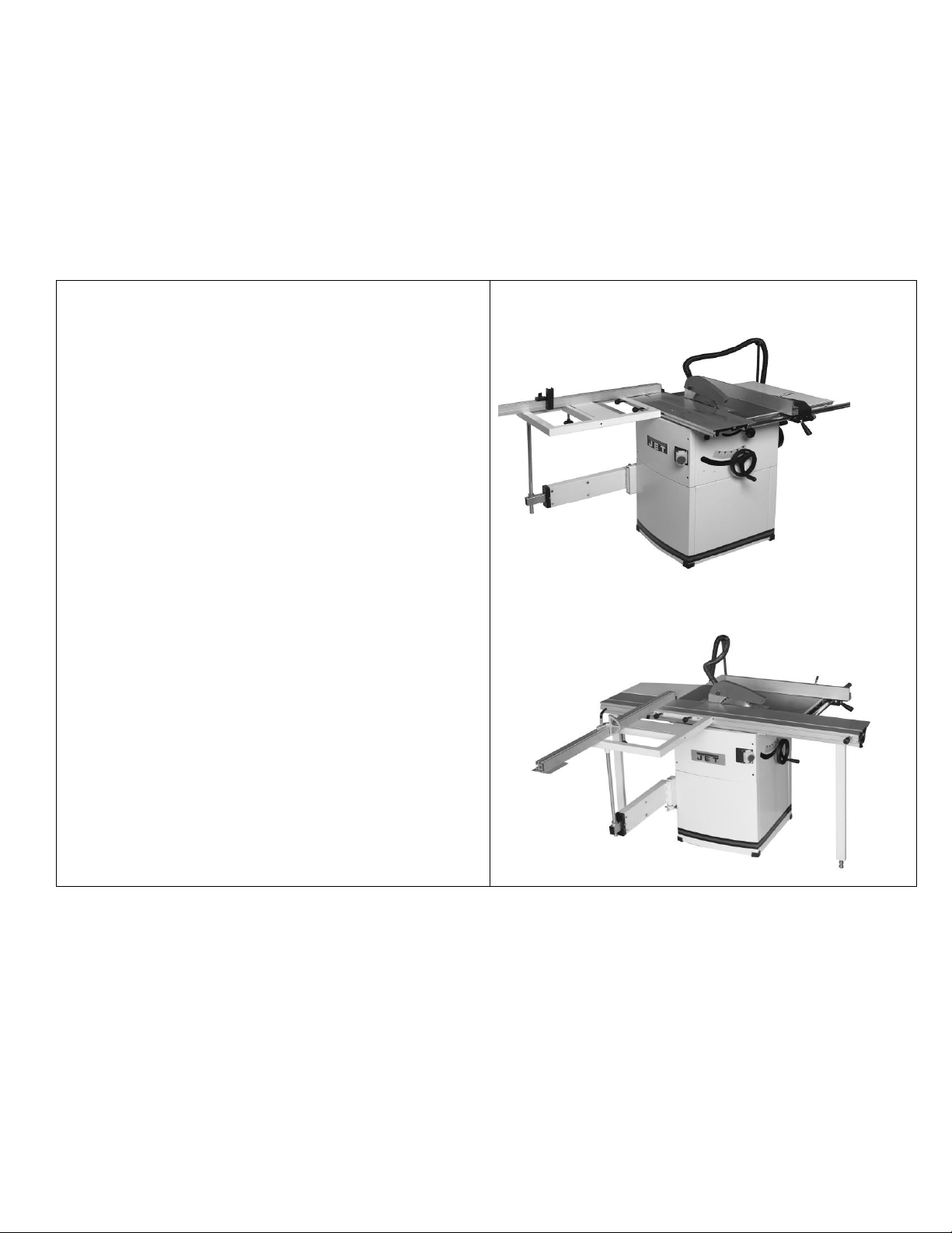
JTS-600X & JTS-600XL TCF
Heavy duty steel machine table completely
galvanized to avoid corrosion.
Separate hand wheel for blade tilt up to 45°
with adjustable stop at 0°.
Powerful induction motor with break to stop the
saw blade in seconds.
A dia. 100mm dust port and upper dust
collection ensure best working conditions.
Anodized aluminium table insert for precise
work piece support and reduced friction.
A sliding table for max 1250mm crosscut and a
right table extension are on option.
JTS-600X PHOTO
JTS-600XL PHOTO
1, Model: JTS-600X, JTS-600XL Table Saw
2, Stock No. : 10000070XM/XT 10000070XLM/XLT
3, Brand: JET
4, Description of products (with photos)
5. Supplier
Qingdao Capital Resource Electric Co. LTD
6. Supplier’s model name
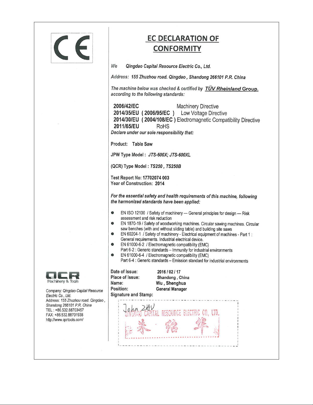
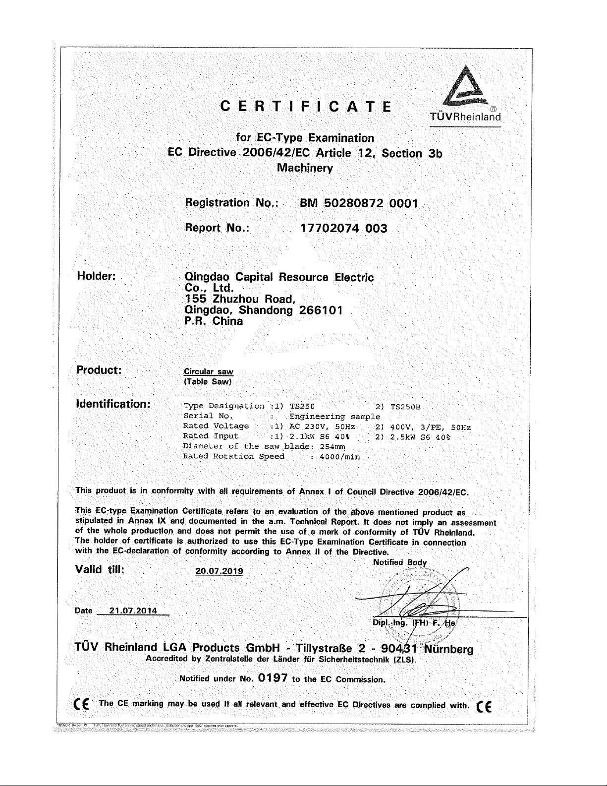
QCR Model: TS250, Ta250B Table Saw
7. Supplier’s CE declaration of conformity with latest directives and EN
standards (including comparison of supplier’s model to JPW’s model)
Page 2
8. JPW’s CE declaration of conformity with latest directives and EN standards
Page 3

CE-Conformity Declaration
CE-Konformitätserklärung
Déclaration de Conformité CE
Product / Produkt / Produit:
Circular Saw Bench
Tischkreissäge
Scie circulaire de table
JTS-600XL-M, JTS-600XL-T
Brand / Marke / Marque:
JET
Manufacturer / Hersteller / Fabricant:
JPW (Tool) AG, Tämperlistrasse 5, CH-8117 Fällanden
Schweiz / Suisse / Switzerland
We hereby declare that this product complies with the regulations
Wir erklären hiermit, dass dieses Produkt der folgenden Richtlinie entspricht
Par la présente, nous déclarons que ce produit correspond aux directives suivantes
2006/42/EC
Machinery Directive
Maschinenrichtlinie
Directive Machines
2014/30/EU
electromagnetic compatibility
elektromagnetische Verträglichkeit
compatibilité électromagnétique
designed in consideration of the standards
und entspechend folgender zusätzlicher Normen entwickelt wurde
et été développé dans le respect des normes complémentaires suivantes
EN ISO 12100:2010
EN 1870-19:2013
EN 60204-1:2006+A1:2009
EN 61000-6-2:2005
EN 61000-6-4:2007+A1:2011
Responsible for the Documentation / Dokumentations-Verantwortung / Résponsabilité de Documentation:
Hansjörg Meier
Head Product-Mgmt. / Leiter Produkt-Mgmt. / Resp. Gestion des Produits
JPW (Tool) AG
2016-07-25 Alain Schmid, General Manager
JPW (Tool) AG, Tämperlistrasse 5, CH-8117 Fällanden
Schweiz / Suisse / Switzerland
Page 4
Page 5
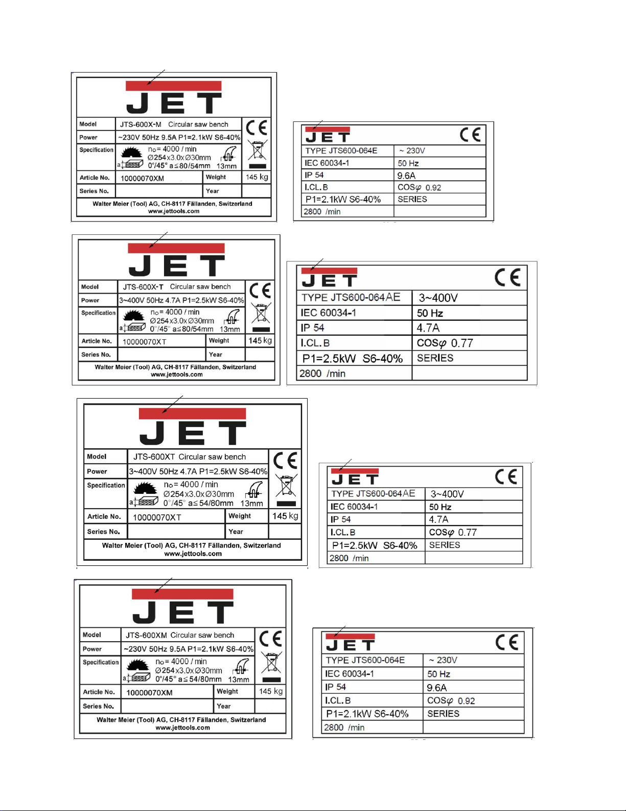
10. Labels (ID label, motor label, warning label…)
Page 6
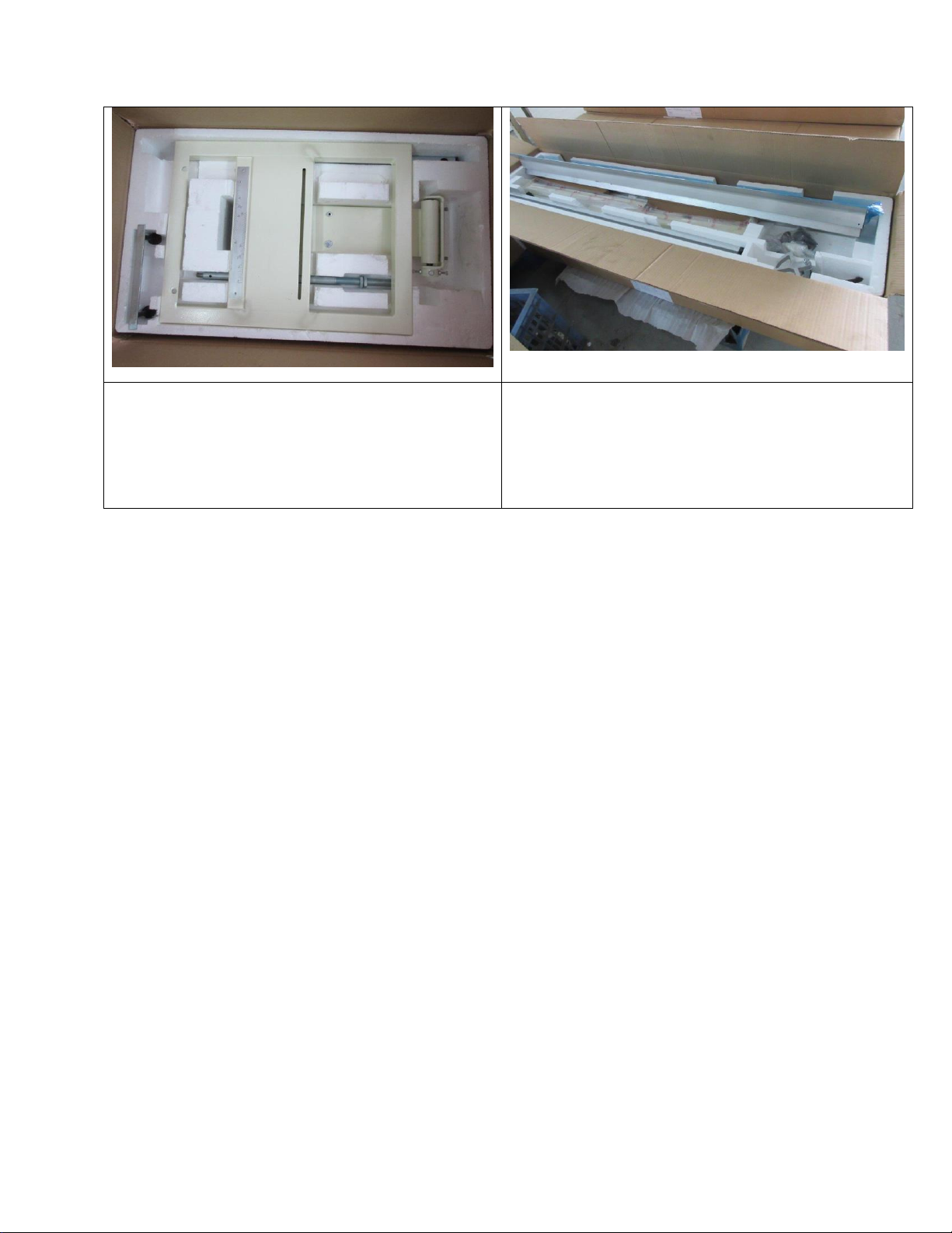
11. Packing information (with photos)
12. User manual (including part list, machine drawings and electric diagrams)
Page 7
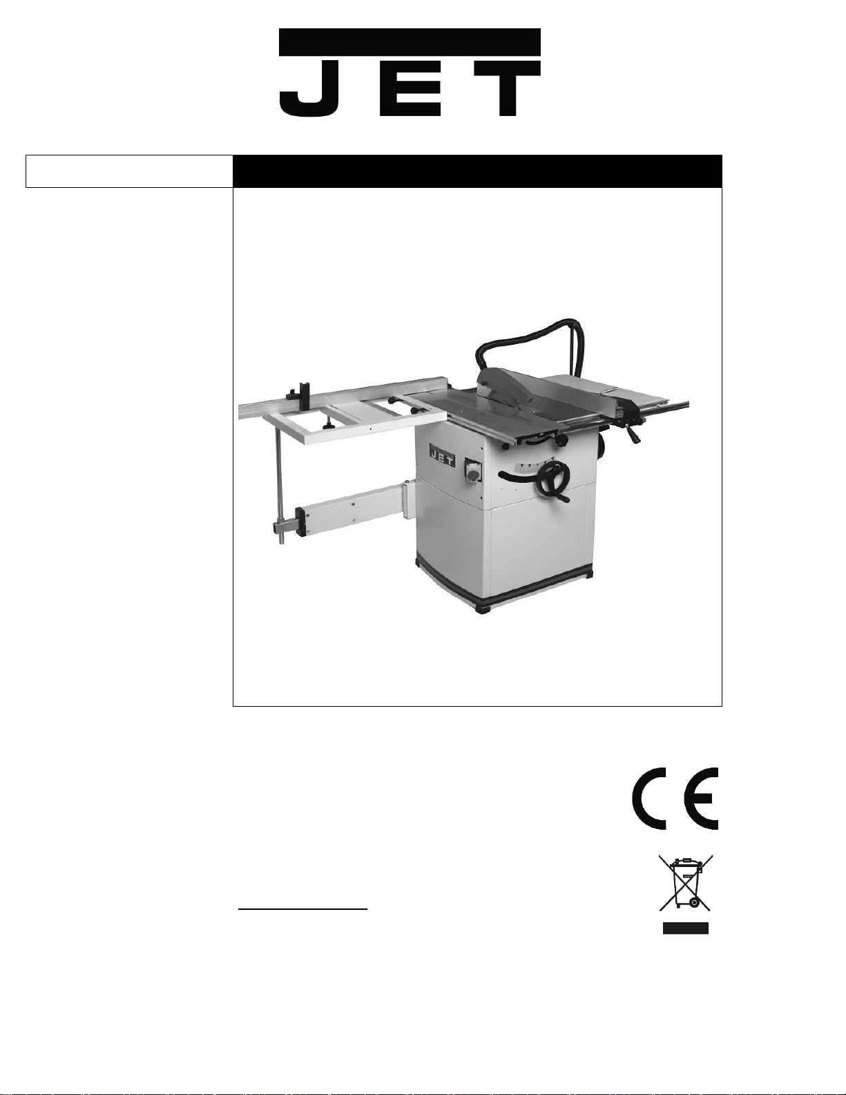
JTS-600X
CIRCULAR SAW BENCH
Original Language:
GB
Operating Instructions
Translations:
D
Gebrauchsanleitung
F
Mode d´emploi
JPW (Tool) AG
Tämperlistrasse 5
CH-8117 Fällanden
Switzerland
Phone +41 44 806 47 48
Fax +41 44 806 47 58
www.jettools.com
M – 10000070XM/XT 2016-03
Page 8

CE-Conformity Declaration
CE-Konformitätserklärung
Déclaration de Conformité CE
Product / Produkt / Produit:
Circular Saw Bench
Tischkreissäge
Scie circulaire de table
JTS-600XL-M, JTS-600XL-T
Brand / Marke / Marque:
JET
Manufacturer / Hersteller / Fabricant:
JPW (Tool) AG, Tämperlistrasse 5, CH-8117 Fällanden
Schweiz / Suisse / Switzerland
We hereby declare that this product complies with the regulations
Wir erklären hiermit, dass dieses Produkt der folgenden Richtlinie entspricht
Par la présente, nous déclarons que ce produit correspond aux directives suivantes
2006/42/EC
Machinery Directive
Maschinenrichtlinie
Directive Machines
2014/30/EU
electromagnetic compatibility
elektromagnetische Verträglichkeit
compatibilité électromagnétique
designed in consideration of the standards
und entspechend folgender zusätzlicher Normen entwickelt wurde
et été développé dans le respect des normes complémentaires suivantes
EN ISO 12100:2010
EN 1870-19:2013
EN 60204-1:2006+A1:2009
EN 61000-6-2:2005
EN 61000-6-4:2007+A1:2011
Responsible for the Documentation / Dokumentations-Verantwortung / Résponsabilité de Documentation:
Hansjörg Meier
Head Product-Mgmt. / Leiter Produkt-Mgmt. / Resp. Gestion des Produits
JPW (Tool) AG
2016-07-25 Alain Schmid, General Manager
JPW (Tool) AG, Tämperlistrasse 5, CH-8117 Fällanden
Schweiz / Suisse / Switzerland
Page 9

GB - ENGLISH
Operating Instructions
Dear Customer,
Many thanks for the confidence you have shown in us with the purchase of your new JET-machine. This manual has been
prepared for the owner and operators of a JET JTS-600X table saw to promote safety during installation, operation and
maintenance procedures. Please read and understand the information contained in these operating instructions and the
accompanying documents. To obtain maximum life and efficiency from your machine, and to use the machine safely, read this
manual thoroughly and follow instructions carefully.
…Table of Contents
1. Declaration of conformity
2. Warranty
3. Safety
Authorized use
General safety notes
Remaining hazards
4. Machine specifications
Technical data
Noise emission
Dust emission
Contents of delivery
Description of machine
5. Transport and start up
Transport and installation
Assembly
Dust connection
Mains connection
Starting operation
6. Machine operation
7. Setup and adjustments
Changing saw blade
Mounting the raving knife
Mounting the saw guard
Rising and tilting saw blade
Sliding table setup
Rip fence setup
Sawblade tilting
Crosscut table setup
Crosscut fence setup
8. Maintenance and inspection
9. Troubleshooting
10. Environmental protection
11. Available accessories
12. „Safe operation” ........ appendix A
1. Declaration of conformity
On our own responsibility we hereby
declare that this product complies with
the regulations* listed on page 2.
Designed in consideration with the
standards**.
CE type examination*** performed
by****.
2. Warranty
The Seller guarantees that the
supplied product is free from material
defects and manufacturing faults. This
warranty does not cover any defects
which are caused, either directly or
indirectly, by incorrect use,
carelessness, accidental damage,
repair, inadequate maintenance or
cleaning and normal wear and tear.
Guarantee and/or warranty claims
must be made within twelve months
from the date of purchase (date of
invoice). Any further claims shall be
excluded.
This warranty includes all guarantee
obligations of the Seller and replaces
all previous declarations and
agreements concerning warranties.
The warranty period is valid for eight
hours of daily use. If this is exceeded,
the warranty period shall be reduced
in proportion to the excess use, but to
no less than three months.
Returning rejected goods requires the
prior express consent of the Seller and
is at the Buyer’s risk and expense.
Further warranty details can be found
in the General Terms and Conditions
(GTC). The GTC can be viewed at
www.jettools.com or can be sent by
post upon request.
The Seller reserves the right to make
changes to the product and
accessories at any time.
3. Safety
3.1 Authorized use
This machine is designed for sawing
wood, wood derived materials as well
as similar to be machined hard
plastics only.
Machining of other materials is not
permitted and may be carried out in
specific cases only after consulting
with the manufacturer.
No metal workpieces may be
machined.
The workpiece must allow to safely be
loaded, supported and guided.
No cuts without using the rip fence,
the 90° fence or the sliding table may
be performed.
No submerged cuts by removing the
riving knife and/or saw guard may be
performed.
The use of a power feeder is not
considered.
The proper use also includes
compliance with the operating and
maintenance instructions given in this
manual.
The machine must be operated only
by persons familiar with its operation,
maintenance and repair and who are
familiar with its hazards.
The required minimum age must be
observed.
The machine must only be used in a
technically perfect condition.
When working on the machine, all
safety mechanisms and covers must
be mounted.
In addition to the safety requirements
contained in this operating instruction
and your country’s applicable
regulations, you should observe the
generally recognized technical rules
concerning the operation of
woodworking machines.
3
Page 10

Any other use exceeds authorization.
In the event of unauthorized use of the
machine, the manufacturer renounces
all liability and the responsibility is
transferred exclusively to the operator.
3.2 General safety notes
Woodworking machines can be
dangerous if not used properly.
Therefore the appropriate general
technical rules as well as the following
notes must be observed.
Read and understand the entire
instruction manual before attempting
assembly or operation.
Keep this operating instruction close
by the machine, protected from dirt
and humidity, and pass it over to the
new owner if you part with the tool.
No changes to the machine may be
made.
Daily inspect the function and
existence of the safety appliances
before you start the machine.
Do not attempt operations in this case,
protect the machine by unplugging the
mains cord.
Remove all loose clothing and confine
long hair.
Before operating the machine, remove
tie, rings, watches, other jewellery, and
roll up sleeves above the elbows.
Wear safety shoes; never wear leisure
shoes or sandals.
Always wear the approved working
outfit :
- safety goggles
- ear protection
- dust protection
Do not wear gloves while operating
this machine.
For the safe handling of sawblades
wear work gloves.
Observe the chapter “save operation”
in this manual.
Check the correct rotation of the
sawblade before operating the
machine.
Do not start cutting operation until
sawblade is at full speed.
Control the stopping time of the
machine, it may not be longer than 10
seconds.
Do not use side pressure to stop
rotating blade.
Insure that the workpiece does not roll
when cutting round pieces.
Use suitable table extensions and
supporting aids for difficult to handle
workpieces.
Always hold and guide the workpieces
safely during machining.
Pay particular attention to instructions
on reducing the risk of kickback.
The supplied raving knife must always
be used. Adjust the space to the
sawblade to be between 2 to 5mm.
Do not perform any operation
freehand.
Never reach around or over the saw
blade.
When ripping narrow workpieces
(<120mm) use as push-stick or pushwood.
Always use crossfeed guide for cutting
off.
The use of dado-blades is not
permissible.
Make sure that small cut off
workpieces will not be caught and
thrown away by the rising saw blade
teeth.
Take care when slotting.
Remove cut and jammed workpieces
only when motor is turned off and the
machine is at a complete standstill.
Install the machine so that there is
sufficient space for safe operation and
workpiece handling.
Keep work area well lighted.
The machine is designed to operate in
closed rooms and must be placed
stable on firm and levelled ground.
Make sure that the power cord does
not impede work and cause people to
trip.
Keep the floor around the machine
clean and free of scrap material, oil
and grease.
Stay alert!
Give your work undivided attention.
Use common sense.
Keep an ergonomic body position.
Maintain a balanced stance at all
times.
Do not operate the machine when you
are tired.
Do not operate the machine under the
influence of drugs, alcohol or any
medication. Be aware that medication
can change your behaviour.
Keep children and visitors a safe
distance from the work area.
Never reach into the machine while it
is operating or running down.
Never leave a running machine
unattended. Before you leave the
workplace switch off the machine.
Do not operate the electric tool near
inflammable liquids or gases.
Observe the fire fighting and fire alert
options, for example the fire
extinguisher operation and place.
Do not use the machine in a dump
environment and do not expose it to
rain.
Wood dust is explosive and can also
represent a risk to health.
Dust form some tropical woods in
particular, and from hardwoods like
beach and oak, is classified as a
carcinogenic substance.
Always use a suitable dust extraction
device
Before machining, remove any nails
and other foreign bodies from the
workpiece.
Specifications regarding the maximum
or minimum size of the workpiece
must be observed.
Do not remove chips and workpiece
parts until the machine is at a
complete standstill.
Never operate with the guards not in
place – serious risk of injury!
Do not stand on the machine.
Connection and repair work on the
electrical installation may be carried
out by a qualified electrician only.
Always unwind any extension cords
fully.
Have a damaged or worn cord
replaced immediately.
Do not use the machine when the ONOFF switch does not operate correctly.
Make all machine adjustments or
maintenance with the machine
unplugged from the power source.
Use only sawblades according to
EN 847-1.
Never use sawblades made from High
Speed Steel (HSS).
Take care that the selection of the saw
blade depends on the material to be
cut.
Remove defective sawblades
immediately.
A worn table insert must be replaced.
4
Page 11
3.3 Remaining hazards
When using the machine according to
regulations some remaining hazards
may still exist
The moving sawblade in the work area
can cause injury.
Broken saw blades can cause injuries.
Thrown workpieces can lead to injury
Tipping of the workpiece due to
insufficient support can lead to injury.
Wood chips and sawdust can be
health hazards. Be sure to wear
personal protection gear such as
safety goggles ear- and dust
protection.
Use a suitable dust exhaust system.
The use of incorrect mains supply or a
damaged power cord can lead to
injuries caused by electricity.
The type and condition of the
sawblade is important in keeping the
noise level as low as possible.
This does not negate the fact that
extra safety equipment such as ear
protection must be used.
4. Machine specifications
4.1 Technical data
Machine Table 800x350 mm
Right extension table 800x270 mm
Rear extension table 415x350mm
Sliding table size 1000x255 mm
Max. travel of sliding table 660 mm
Max. length of cut 610 mm
Sawblade diameter max 250 mm
Blade bore diameter 30 mm
Blade speed n0 4000 rpm
Cutting height at 90°/45° 80/54 mm
Tilting range of blade 90°- 45°
Max. width of rip cut 610 mm
Dust port diameter 100mm
Weight 145 kg
Mains 230V ~1/N/PE 50Hz
Motor output power 1,5kW (2HP) S1
Reference current 9.6 A
Extension cord (H07RN-F): 3x1,5mm²
Installation fuse protection 16A
Mains 400V ~3/PE 50Hz
Motor output power 1,5 kW (2 HP) S1
Reference current 4.7 A
Extension cord (H07RN-F): 4x1,5mm²
Installation fuse protection 16A
4.2 Noise emission
Determined according to EN 1870-1
(Inspection tolerance 4 dB)
Workpiece plywood 16mm:
Acoustic power level
(according to EN ISO 3746):
Idling LwA 98,2 dB (A)
Operating LwA 101,8 dB (A)
Acoustic pressure level
(according to EN ISO 11202):
Idling LpA 84,2 dB (A)
Operating LpA 88,5 dB (A)
The specified values are emission
levels and are not necessarily to be
seen as safe operating levels.
This information is intended to allow
the user to make a better estimation of
the hazards and risks involved.
4.3 Dust emission
The circular saw has been dust
emission evaluated.
At an air velocity of 20m/sec on the
dust port dia. 100mm:
Vacuum pressure 850Pa
Volume flow 565 m³/h
The TRK-value of 2 mg/m3 is not
exceeded.
4.4 Content of delivery
Machine stand
Sliding table
Crosscut table
Crosscut fence
Telescopic arm
Rare extension table
Right extension table
Rip fence with dual fence profile
Rip fence support bar
Saw guard
Sawblade 250mm
Dust connection hose and Y-adapter
Hose tye
Push stick
Operating tools
Assembly bag
Operating manual
Spare parts list
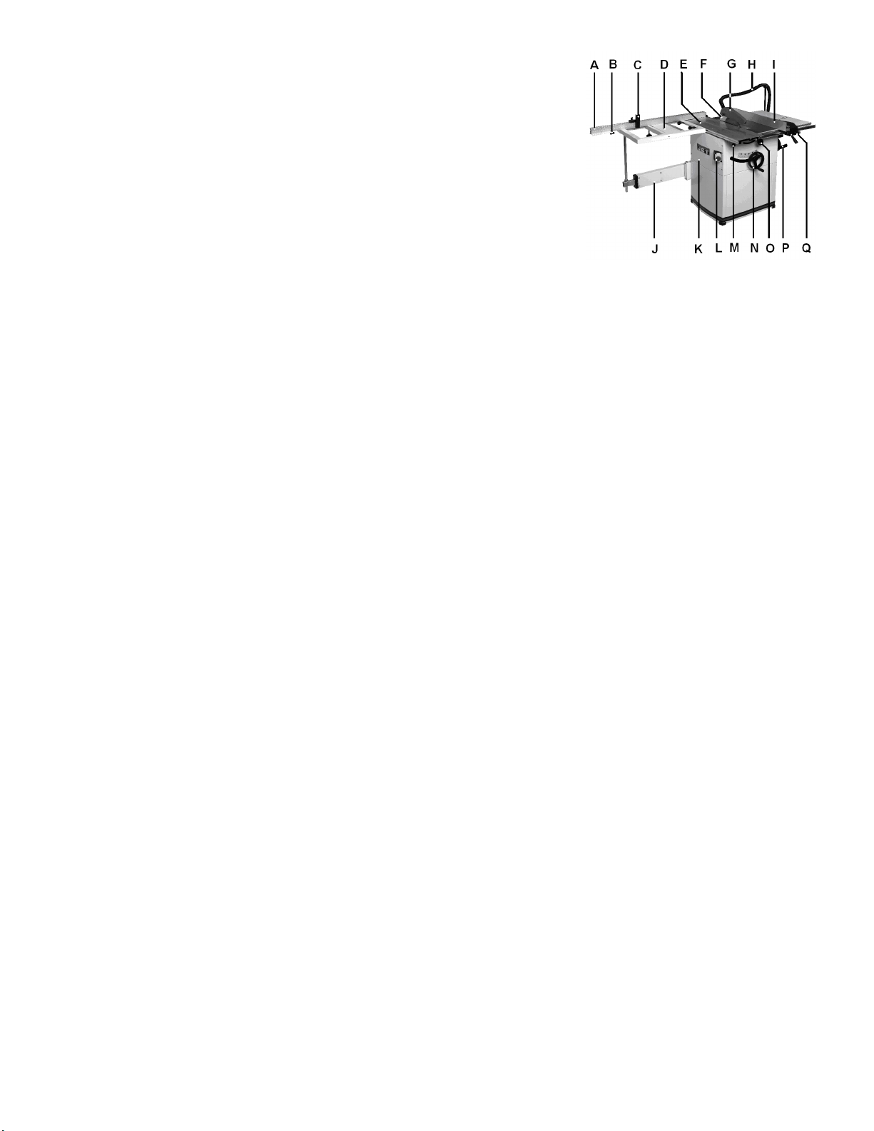
4.5 Description of machine
Fig 1
A…...Crosscut fence
B…..Pull out lock knob
C….Crosscut stop
D…..Crosscut table
E…..Sliding table
F…..Raving knife
G…..Saw guard
H….Dust connection hose
I…..Rip fence
J…...Telescopic arm
K….Front cabinet cover
L….On/ Off switch
M….Sliding table lock
N….Blade rise handwheel
O….Blade tilt lock
P….Blade tilt handwheel
Q….Rip fence micro adjustment
5. Transport and start up
5.1 Transport and installation
For transport to the desired location
use a forklift or hand trolley. Make
sure the machine does not tip or fall
off during transport.
The machine is designed to operate in
closed rooms and must be placed
stable on firm and levelled ground.
The machine must be levelled in both
directions to assure good sliding
motion of the sliding table.
If possible, the machine must be
placed on rubber plates which act as
shock absorbers and reduce the noise
level.
For packing reasons the machine is
not completely assembled.
5
Page 12
5.2 Assembly
If you notice any transport damage
while unpacking, notify your supplier
immediately. Do not operate the
machine!
Dispose of the packing in an
environmentally friendly manner.
Clean all rust protected surfaces with
a mild solvent.
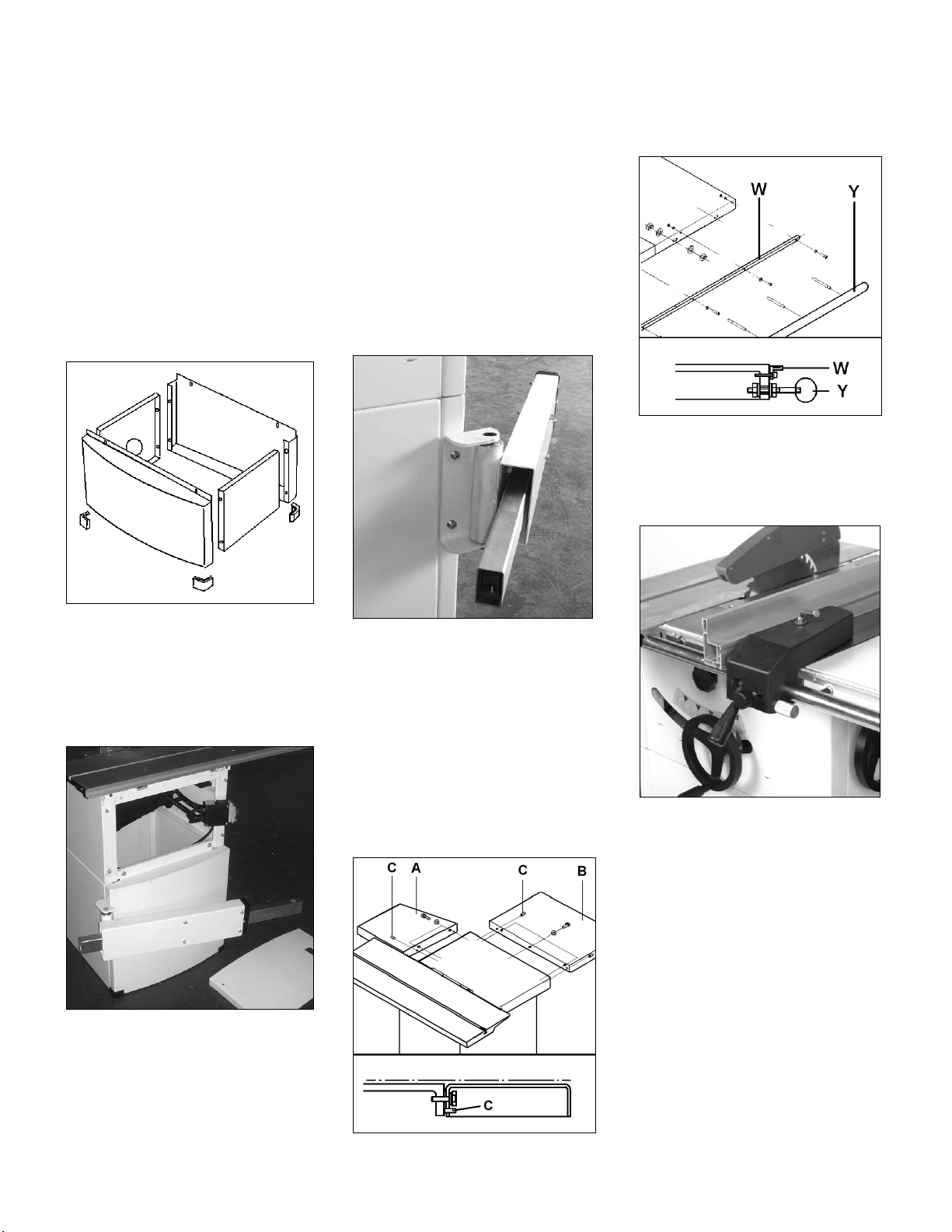
Mounting machine stand:
Attach the side panels to the front and
rear panel with the supplied bolts, flat
washers and nuts.
Attach the 4 rubber pads.
Warning:
The machine is heavy (145 kg)!
Assure the sufficient load capacity
and proper condition of your lifting
devices.
Never step underneath suspended
loads.
Attach the machine to the stand with
the supplied hex socket bolts and
washers.
Mounting telescopic arm:
Place the mounting plate on the inside
of the cabinet and attach the
telescopic arm with the supplied hex
socket bolts (Fig 4)
Mounting rip fence support bar
Mount the rip fence support bar (Y, Fig
6) to the front of the saw table and
right table extension.
Fig 6
Mount the scale carrier (W).
Mounting rip fence
Mount the rip fence to the rip fence
support bar.
Fig 2
Mounting machine to stand:
Access the machine inside by
removing the front cabinet cover
(bayonet mount, loosen screws and lift
off the cover, Fig 3)
Fig 3
Use lifting straps to lift the machine.
Fig 4
Mounting table extensions
Attach rear extension table (A, Fig 5)
to the machine table with hex head
screws and washers.
Attach right extension table (B) to the
machine table with hex head screws
and washers.
Put table surfaces in level to the main
table.
Use the rip fence profile to check and
the grub screws (C) to adjust.
Fig 7
The rip fence must be guided parallel
to the table surface. Adjust the round
bar (Y) up-down as needed.
Mounting sliding table:
Loosen the screws and lift the sliding
table end covers
Loosen 2 screws and lift the sliding
table end cover.
Slide the sliding table carefully over
the 4 guide rollers (Fig 8).
Fig 5
6
Page 13
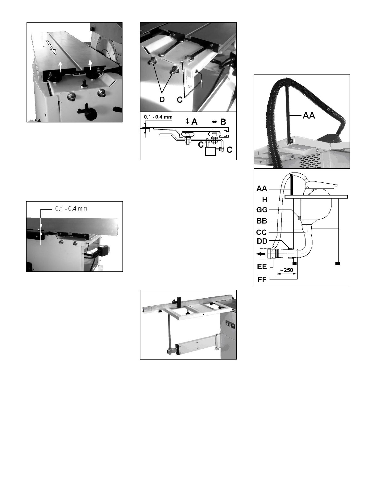
Fig 8
Lower the sliding table end cover and
tighten screws.
Sliding Table Adjustment:
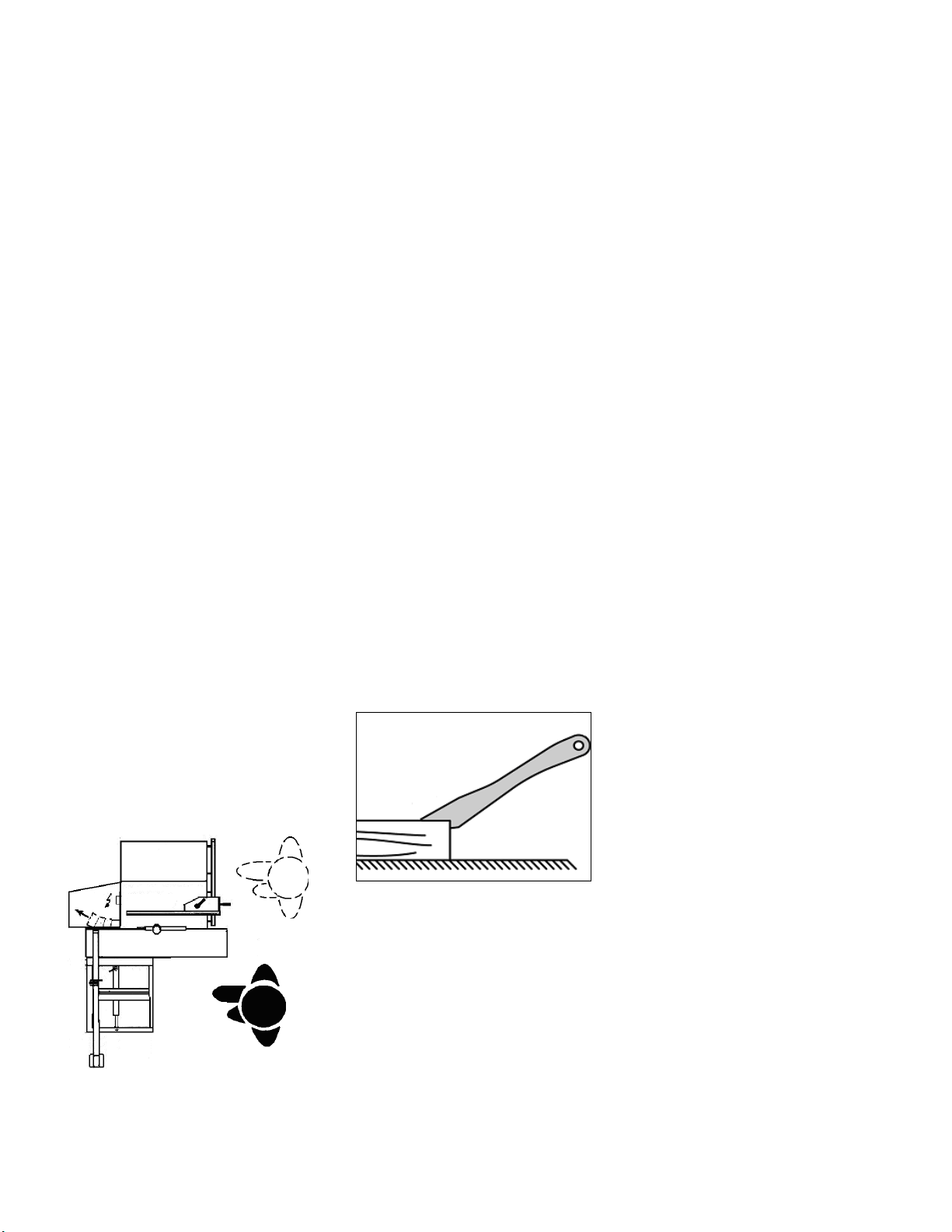
The sliding table is adjusted ex works.
The sliding table must be aligned to
run parallel to the sawblade and table
surface to be 0,1 - 0,4 mm higher than
the machine table. Use rip fence
profile to check (Fig 9).
Fig 9
Adjustment:
The sliding table guide assembly can
be adjusted up-down and parallel to
the sawblade.
Loosen the nuts (D, Fig 10) as
needed.
Grub screws (C) allow a guided
adjustment in vertical and horizontal
direction.
Fig 10
The sliding table guide rollers can be
used for micro adjustments.
A) Adjustable in height, for precise
alignment to the machine table
B) Excentric shafts, for backlash-free
movement of the roller guide.
Mounting Sawblade
See chapter 7.1
Adjusting Raving Knife
See chapter 7.2
Mounting Saw Guard
See chapter 7.3
Mounting crosscut table
See chapter 7.8
Fig 11
Mounting crosscut fence
See chapter 7.9
5.3 Dust connection
Before initial operation, the machine
must be connected to a dust extractor.
The suction should switch on
automatically when the saw is
switched on.
A connecting hose, a hose support, a
Y-piece and a hose tye are supplied
with the machine.
Mounting Hose Support:
Attach the hose support (AA, Fig 12)
to the table extension with the
supplied fastening clip.
Fig 12
Mount the plastic hose protection tube
(DD) into the machine stand.
Mount at a distance of approximately
250mm to the end an additional hose
tye (FF). This will protect the hose
from pulling out .
Mount the Y-piece (EE) and the
connecting hose (H) for the upper dust
collection.
The flow rate on the suction port dia.
100mm must be 20m/sec.
Flexible hoses must be of nonflammable quality, and must be
connected to the machine ground
system.
5.4 Mains connection
Mains connection and any extension
cords used must comply with
applicable regulations.
7
Page 14
The mains voltage must comply with
the information on the machine licence
plate.
The mains connection must have a
16A surge-proof fuse.
Only use connection cables marked
H07RN-F
Connections and repairs to the
electrical equipment may only be
carried out by qualified electricians.
Attention:
-Check first if the saw spindle runs
freely and if all safety devices are
fitted before starting the machine.
For safety reasons this must only be
done without the sawblade installed!
- If the direction of rotation is not
correct, the phase converter inside the
CCE Euro plug must be pushed in and
turned 180°.
(Clockwise direction of the spindle is
correct).
5.5 Starting operation
You can start the machine with the
green On-button. The red Off-button
stops the machine.
In case of machine overload the motor
overload cut-off will react.
After appr.10 min of cooling the
machine can be started again.
350
6. Machine operation
Correct working position:
In front of the machine standing out of
the line of cutting (danger zone).
Fig 13
Workpiece handling:
Hands placed flat on the workpiece
outside the cutting area.
Feed the workpiece towards the saw
blade in the direction of the saw line.
Push the workpiece steadily forward;
complete the cut as a single
movement.
Support long and wide workpieces
with helping roller stands.
The use of a power feeder is not
considered.
Operating hints:
Work only with a sharp and flawless
sawblade.
Take care that the selection of the saw
blade depends on the material to be
cut.
Use a suitable wedge to prevent round
timber from turning under the pressure
of the cut.
Use suitable table extensions and
supporting aids for difficult to handle
workpieces.
Always hold and guide the workpieces
safely during machining.
Do not perform any operation
freehand.
Take care when slotting.
When ripping narrow workpieces
(<120mm) use as push-stick or pushwood.
Fig 14
Make sure that small cut off
workpieces will not be caught and
thrown away by the rising saw blade
teeth.
Remove cut and jammed workpieces
only when motor is turned off and the
machine is at a complete standstill.
Pay particular attention on reducing
the risk of kickback.
The supplied raving knife must always
be used.
For the authorized use of the
machine observe the appendix A
“safe operation“
(on the last pages of this operating
manual)
A.1.: Ripping
A.2.: Ripping of narrow stock
A.3.: Crosscutting on rip fence
A.4.: Use of push wood handle
7. Setup and adjustments
General note:
Setup and adjustment work may
only be carried out after the
machine is protected against
accidental starting by pulling the
mains plug.
7.1 Changing sawblade
The sawblade has to meet the
technical specification.
Use only sawblades according to EN
847-1
The maximum diameter of the saw
blades used on the machine is 250
mm.
Check sawblade for flaws (cracks,
broken teeth, bending) before
installation. Do not use faulty
sawblades.
Warning:
The use off HSS saw blades is
prohibited; use only carbide tipped
saw blades.
The sawblade teeth must point in
cutting direction (down)
Always wear suitable gloves when
handling sawblades.
WARNING:
When installing or changing saw
blade, always disconnect saw from
power source, unplug!
Remove the crosscut table.
Remove the sliding table.
Raise the main sawblade to its highest
position.
Remove the saw guard.
Changing saw blade:
Loosen the arbor nut (J, Fig 15) while
stopping the arbor against rotation
with the locking pin (K).
8
Page 15
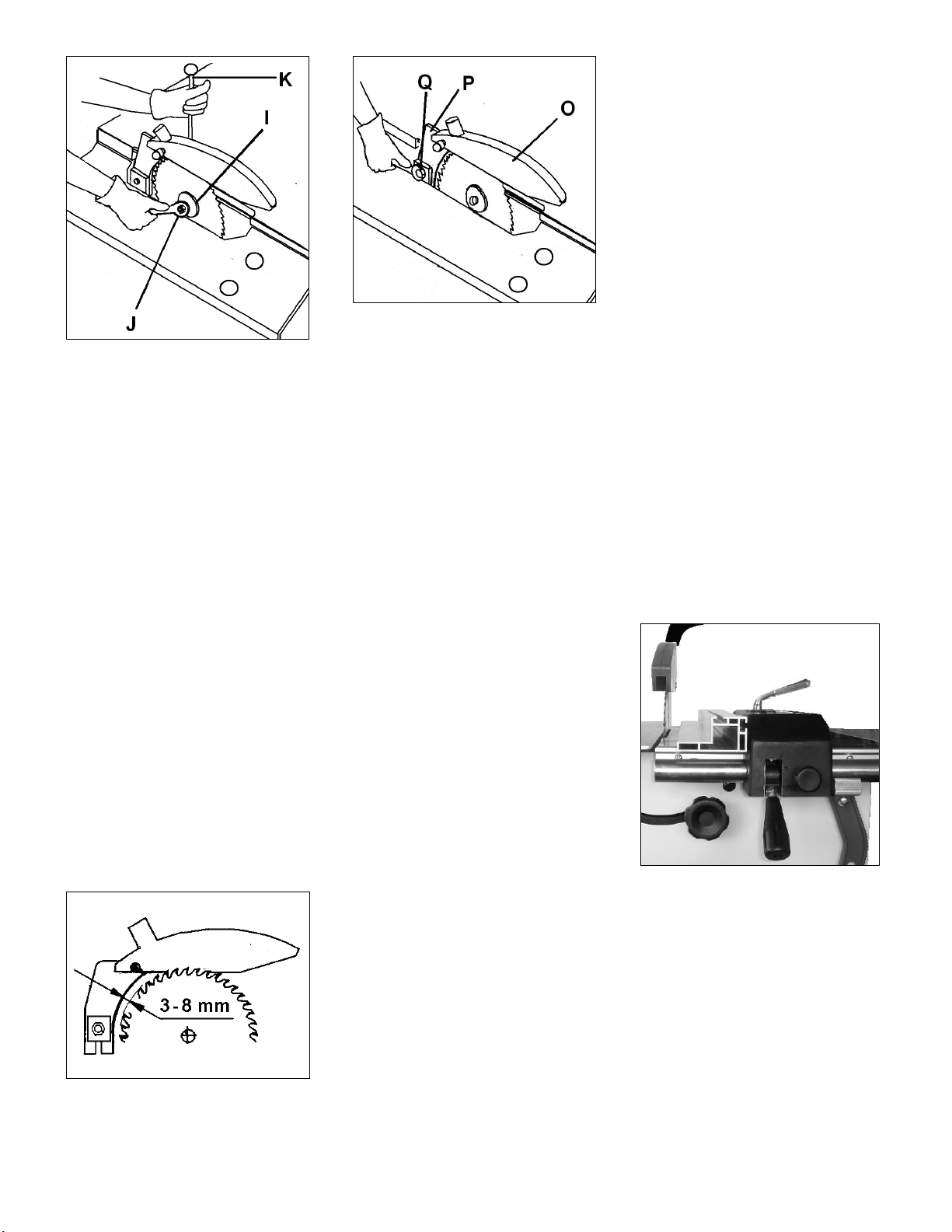
Fig 15
Attention: left hand thread.
Remove the arbor nut (J) and flange
(I).
Place saw blade on arbor shaft
making sure teeth point down at the
front of the saw.
Reinstall flange, washer and arbor nut
and securely tighten.
Remove the locking pin (K).
Check the correct position of the
raving knife in regards to the saw
blade (see Chapter 7.2).
Reinstall the saw guard and the sliding
table.
7.2 Mounting the raving knife
The supplied raving knife must always
be used.
The machine is equipped with a raving
knife for the use of sawblades
diameter 250 mm.
The raving knife has to be adjusted in
such a way that over its entire length
the gap between sawblade and raving
knife does not exceed min. 3 mm and
max. 8 mm (Fig 16).
Fig 16
The raving knife (P, Fig 17) can be
adjusted in both vertical and horizontal
direction.
Fig 17
The height setting has to be adjusted
in such a way that the sawguard
bottom never exceeds more than 3
mm above the highest placed
sawblade tooth.
After height adjustment always locks
the central bolt (Q).
Never remove this raving knife.
Kickbacks are severe and very
dangerous.
No submerged cuts by removing the
raving knife and/or saw guard may be
performed.
7.3 Mounting the saw guard
The sawguard (O, Fig 17) must always
be used.
Attach the saw guard to the raving
knife (P).
The sawguard must be lowered to the
workpiece to minimise the amount of
exposed teeth.
Adjustment shall never be performed
when the machine is running.
The saw guard has to be connected to
the dust extractor system.
7.4 Rising and tilting sawblade
Setup adjustments of the sawblade
shall never be performed when the
machine is running.
Use the front hand wheel to raise the
sawblade (one turn of the handwheel
equals to approximately 3 mm of
height setting).
Use the right hand wheel to tilt the
sawblade.
9
Both 45° and 90° positive stops are
factory set.
Start the machine with care.
7.5 Sliding table setup
Sliding table setup shall never be
performed when the machine is
running.
When loading panels and when rip
cutting the sliding table must be
locked.
It is recommended to clean the sliding
table once a week, and to remove all
sawdust and chips which gradually
slow down the sliding table.
Never use oil or grease!
7.6 Rip fence setup
Rip fence setup shall never be
performed when the machine is
running.
Note:
The rip fence profile can be placed flat
and adjusted in length.
-The cutting of small work pieces
(width less than 120mm) shall only be
performed with the rip fence profile
placed flat (Fig 18).
Fig 18
When cross cutting using the rip
fence, to avoid the wood getting stuck
between the fence and the riving knife
(resulting in a highly dangerous
kickback) it is necessary to position
the fence so that its end corresponds
with the front of the sawblade (Fig 19).
Page 16
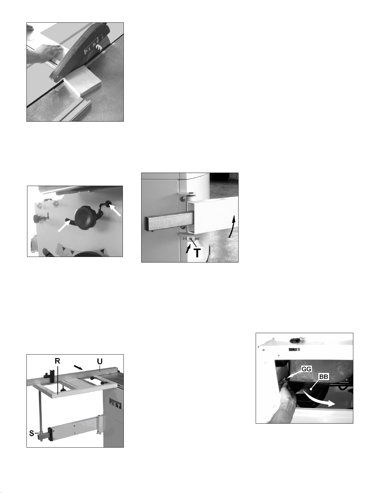
Fig 19
Start the machine with precaution.
7.7 Blade tilt 45° and 90° positive
stop adjustment
The blade tilt positive stops can be
adjusted with an allen key (Fig 20).
Fig 20
7.8 Crosscut table setup
Crosscut table setup shall never be
performed when the machine is
running.
Lift the crosscut table (R, Fig 21) onto
telescopic arm and slide onto sliding
table T-groove and lock in place).
Fig 21
Crosscut table and telescopic arm are
rough aligned ex works (The table
surface must be in level with the
sliding table).
Telescopic arm adjustment:
Mount the crosscut table at the rear of
the sliding table.
Move the sliding table to the rear and
align the crosscut table height with hex
nuts (S).
Use crosscut fence profile (U) to
check.
Move the sliding table forward.
For example: if the crosscut table falls,
tighten the left adjust screw (T, Fig 22)
until the crosscut table does not move
in height during sliding table travel.
Loosen and tighten the adjust screws
and lock nuts as needed.
Fig 22
Finish alignment by setting crosscut
table and machine table in level with
nuts (S).
Lock the nuts (S, Fig 21) against each
other.
Start the machine with care.
7.9 Crosscut fence setup
Crosscut fence setup shall never be
performed when the machine is
running.
The cross-cut table has 2 precision
holes, allowing the crosscut fence to
be put in 2 positions:
At the back and front of the crosscut
table.
Simply put the fence onto the crosscut table and lock it in position using
the supplied knobs.
The 90° adjustable stops (R, Fig 21)
are factory set.
The fence scale is factory set.
Adjustment can be made by moving
the pivot point along the T-grove.
Confirm by test cuts.
10
When, after some time, the plastic
protection cap at the front on the
cross-cut fence is cut away, a new one
has to be installed
(part no.: JTS600-178).
8. Maintenance and inspection
General notes:
Maintenance, cleaning and repair
work may only be carried out after
the machine is protected against
accidental starting by pulling the
mains plug.
Repair and maintenance work on the
electrical system may only be carried
out by a qualified electrician.
Inspect the proper function of the dust
extraction daily.
Keep the inside of the cabinet clear of
sawdust and wood chips. Make sure
the motor fan and fan cover are also
kept clear of sawdust.
All protective and safety devices must
be re-attached immediately after
completed cleaning, repair and
maintenance work.
Defective safety devices must be
replaced immediately.
A worn table insert must be replaced.
Removal of dust chute blockage:
Cut off pieces can block off the chip
flow in the lower saw guard.
Disconnect the machine form the
power source, pull mains plug.
Remove the front cabinet cover.
Remove the lock knob (GG, Fig 23)
and lower the dust port (BB).
Fig 23
Remove blocking parts.
Reinstall the dust port and front
cabinet cover immediately.
Page 17
Cleaning:
Clean the machine regularly.
Remove rust from the table e.g. with
WD-40 and a Scotch-Brite™ Hand
Pad.
Never smoke while cleaning the
machine, and especially when using
petrol, kerosene or other inflammable
products.
This could lead to an explosion and
serious burns for the operator.
Saw blades:
Check saw blades regularly for faults.
Replace a defective sawblades
immediately.
Only use sharp and properly set saw
blades.
The servicing of saw blades should
only be performed by a trained person.
Main drive belt tensioning:
The machine is equipped with a
durable Poly-V belt
In case of belt slip (yelling noise), the
belt must be tightened.
Disconnect the machine form the
power source, pull mains plug.
Remove the front cabinet cover.
Tilt the sawblade to 45° for better
access.
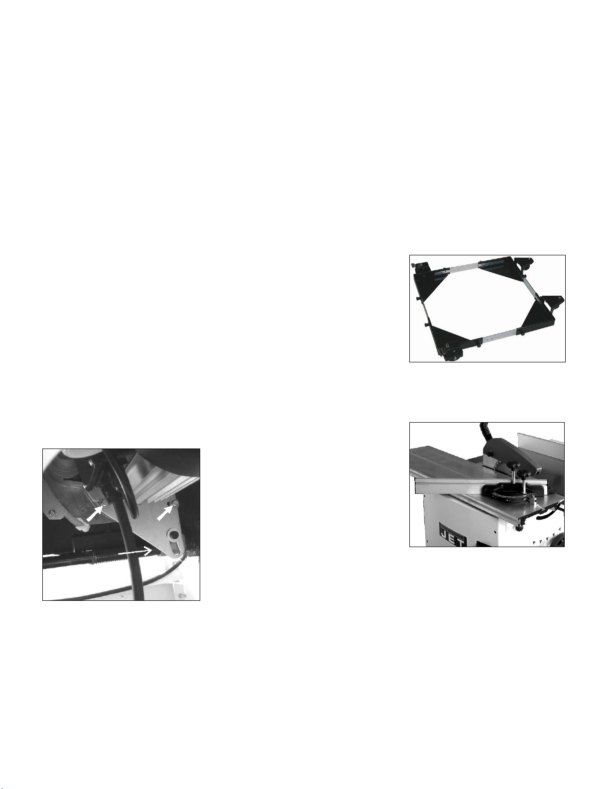
Loosen the 2 hex bolts (Fig 24).
Fig 24
Tension the belt by lowering the
sawblade (spindle nut moves the
motor pivot plate).
Make sure the belt is not over
tensioned, because this could lead to
damage of the saw arbor and
bearings.
Tighten the bolts.
Reinstall front cabinet cover.
Motor Break:
The motor break works electromechanically (break motor).
If breaking time should exceed 10
seconds, the motor break assembly
needs to be replaced. Contact your Jet
service station immediately.
9. Trouble shooting
Motor doesn’t start
*No electricitycheck mains and fu se.
*Defective switch, motor or cordconsult an electrician.
*Overload has reactedWait and start again.
Machine vibrates excessively
*Stand on uneven floor-
adjust levelling screws for even
support.
*dust on saw flangesclean saw arbor and flanges.
*defective sawblade replace sawblade immediately
*Bad Poly-V-beltreplace Poly-V-belt
Cut is not accurately square
*Stops not adjusted correctlycheck with square and adjust stops.
Material binds blade when
ripping
*Fence not aligned with sawbladecheck and adjust rip fence.
*Wrapped woodselect another piece of wood.
Material kicked back from blade
*Fence not aligned with sawbladecheck and adjust rip fence.
*Raving knife not in placehigh danger, mount immediately with
guard.
Cutting surfaces is bad
*Wrong sawblade used
*Blade mounted backwards
*resin collection on sawblade
*sawblade is dull
*workpiece inhomogeneous
*Feed pressure too highDo not force the workpiece.
Blade does not raise or tilt
*Sawdust in mechanismsclean and regrease.
Sliding table does not move
*Sawdust in bearing guideswipe out any sawdust.
Low cutting performance
*Poly-V belt slips Tension main drive belt.
*Wrong voltage Check electric power supply
10. Environmental protection
Protect the environment.
Your appliance contains valuable
materials which can be recovered or
recycled. Please leave it at a
specialized institution.
11. Available accessories
Stock number 708118
Universal mobile base 250kg
Fig 25
Stock number 10000073
Precision mitre gauge with adjustable
stops -45° / 90° / +45°
Fig 26
Refer to the JET-Pricelist
for various accessories.
12. Safe operation
See appendix A (on the last pages of
this operating manual)
A.1.: Ripping
A.2.: Ripping of narrow stock
A.3.: Crosscutting on ripfence
A.4.: Use of push wood handle
11
Page 18
JTS-600X
TABLE SAW
JTS-600X…10000070XM….230/50/1
JTS-600X….10000070XT….400/50/3
PARTS LIST
ERSATZTEILLISTE
LISTE DE PIECES
JPW (Tool) AG
Tämperlistrasse 5
CH-8117 Fällanden
Switzerland
Phone +41 44 806 47 48
Fax +41 44 806 47 58
www.jettools.com
P-10000070XM/XT 2015-08
Page 19
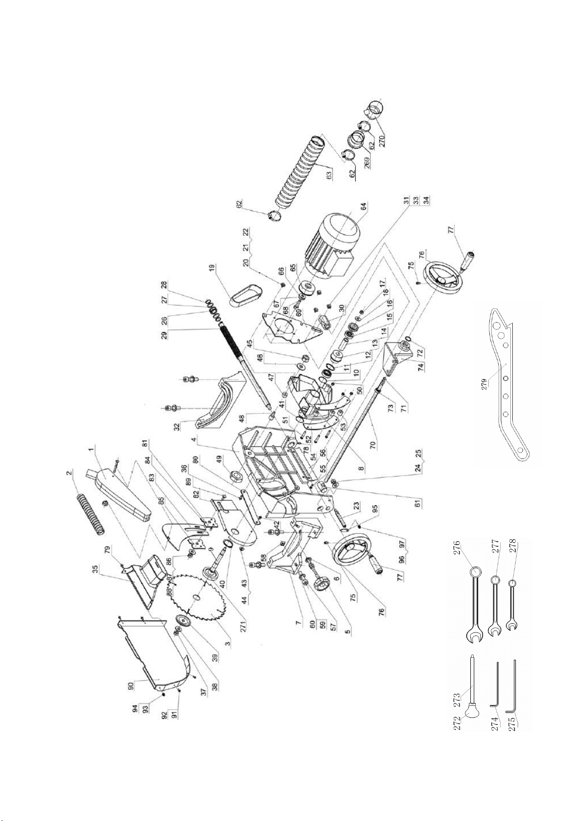
Trunnion Assembly for JTS-600X
Page 20

Trunnion Assembly for JTS-600X
Index
Part No.
Description
Size
Qty.
1
JTS600-001
Blade guard assy
1
2
JTS600-002
Dust collection tube(small)
1 3
JTS600-003
Blade
Ø250x3x Ø 30-36T
1 4 JTS600-004
Mount adjusting base
1 5
JTS600-005
Locking handle assy
1 6
JTS600-006
Washer
M8
1
7
JTS600-007
Rotating support base A
1
8
JTS600-008
Mount base
1 9
JTS600-009
Main shaft
1 10
JTS600-010
Adjusting washer
4 11
JTS600-011
Bearing
6003-RZ
1
12
JTS600-012
Retaining ring
1
13
JTS600-013
Shaft pulley
1 14
JTS600-014
Tube
1 15
JTS600-015
Bearing
6301-RZ
1
16
JTS600-016
Adjusting wheel
1 17
JTS600-017
Nut
M8
1
18
JTS600-018
Washer
M8
1
19
JTS600-019
Poly-belt
1 20
JTS600-020
Hex screw
M6X30
3
21
JTS600-021
Washer
M6 3 22
JTS600-022
Washer
M6 3 23
JTS600-023
Indicator rod
1
24
JTS600-024
Nut
M8
1
25
JTS600-025
Washer
M8 1 26
JTS600-026
Tube
1 27
JTS600-027
Washer
2 28
JTS600-028
Retaining ring
2
29
JTS600-029
Thread rod
1
30
JTS600-030
Thread tube
1 31
JTS600-031
Tube
1 32
JTS600-032
Rotating support base B
1 33
JTS600-033
Position screw
1 34
JTS600-034
Washer
M8
1
35
JTS600-035
Dust funnel
1
JTS600-035A
Funnel&hose clamp assly.(35, 62)
1 36
JTS600-036
Scew
1 37
JTS600-037
Right hand nut
M10X1.5
1
38
JTS600-038
Washer
M10
1
39
JTS600-039
Blade flange
1
40
JTS600-040
Retaining ring
1
41
JTS600-041
Washer
2 42
JTS600-042
Scew
M6X20
1
43
JTS600-043
Nut
M6 1 44
JTS600-044
Washer
M6 2 45
JTS600-045
Nut
M8
1
46
JTS600-046
Washer
M8
1
47
JTS600-047
Tube II
1 48
JTS600-048
Position screw
1 49
JTS600-049
Nut
M6 1 50
JTS600-050
Nut
M6
3
51
JTS600-051
Screw
M6X35
3
52
JTS600-052
Clamping plate
2 53
JTS600-053
Tube I
3
54
JTS600-054
Guard for thread rod
1 55
JTS600-055
Washer
M6
2
Page 21

Trunnion Assembly for JTS-600X
Index
Part No.
Description
Size
Qty.
56
JTS600-056
Pan head screw
M6X8
2
57
JTS600-057
Nut
M8X20
2
58
JTS600-058
Square Nut
2 59
JTS600-059
Washer
M8 2 60
JTS600-060
Internal washer
M8
2
61
JTS600-061
45degree tilting rod
1
62
JTS600-062
Hose clamp
3 63
JTS600-063
Dust collection hose(big)
1 64
JTS600-064E
Motor 230V/50Hz/1
1
JTS600-064AE
Motor 400V/50Hz/3
1
JTS600-064RCE
Running Capacitor (not shown)
(20uF/450VAC)
1
JTS600-064-B
Motor Break replacement parts
assembly (not shown)
1
65
JTS600-065
Motor pulley
1
66
JTS600-066
Anti back washer
1
67
JTS600-067
Washer
M8
1
68
JTS600-068
Screw
1
69
JTS600-069
Motor mounting bracket
1 70
JTS600-070
Tilting thread rod
1 71
JTS600-071
Clamping ring
M12
1
72
JTS600-072
Clamping ring
M22
1
73
JTS600-073
Joint bearing
1
74
JTS600-074
Bracket for joint bearing
1
75
JTS600-075
Screw
M6X16
2
76
JTS600-076
Big handle wheel
2 77
JTS600-077
Handle
2 78
JTS600-078
Scew
M6X10
1
79
JTS600-079
Knob
1
80
JTS600-080
Connecting plate
1 81
JTS600-081
Hex socket screw
M6x10
3
82
JTS600-082
Bracket for riving knife
1 83
JTS600-083
Riving knife
1 84
JTS600-084
Guide plate
1
85
JTS600-085
Press plate
1
86
JTS600-086
Washer
M10
1
87
JTS600-087
Nut
M10
1
88
JTS600-088
Spring washer
M10
1
89
JTS600-089
Screw
M10X25
1
90
JTS600-090
Inside blade guard
1
91
JTS600-091
Screw
M4X10
3
92
JTS600-092
Washer
M5 5 93
JTS600-093
Screw
M4X20
2
94
JTS600-094
Self lock nut
M4 2 95
JTS600-095
Angle indicator
1 96
JTS600-096
Washer
M4
1
97
JTS600-097
Screw
M4X8
1
269
JTS600-269
Cabinet adapter
1
270
JTS600-270
Hose adapter (Y-piece)
1 271
JTS600-271
Blade flange
1 272
JTS600-272
Ball handle
1
273
JTS600-273
Handlebar
1
274
JTS600-274
Allen key
6mm
1
275
JTS600-275
Allen key
5mm
1
276
JTS600-276
Socket wrench
16mm
1
277
JTS600-277
Socket wrench
13mm
1
278
JTS600-278
Socket wrench
10mm
1
279
JTS600-279
Pushing handle
1
Page 22
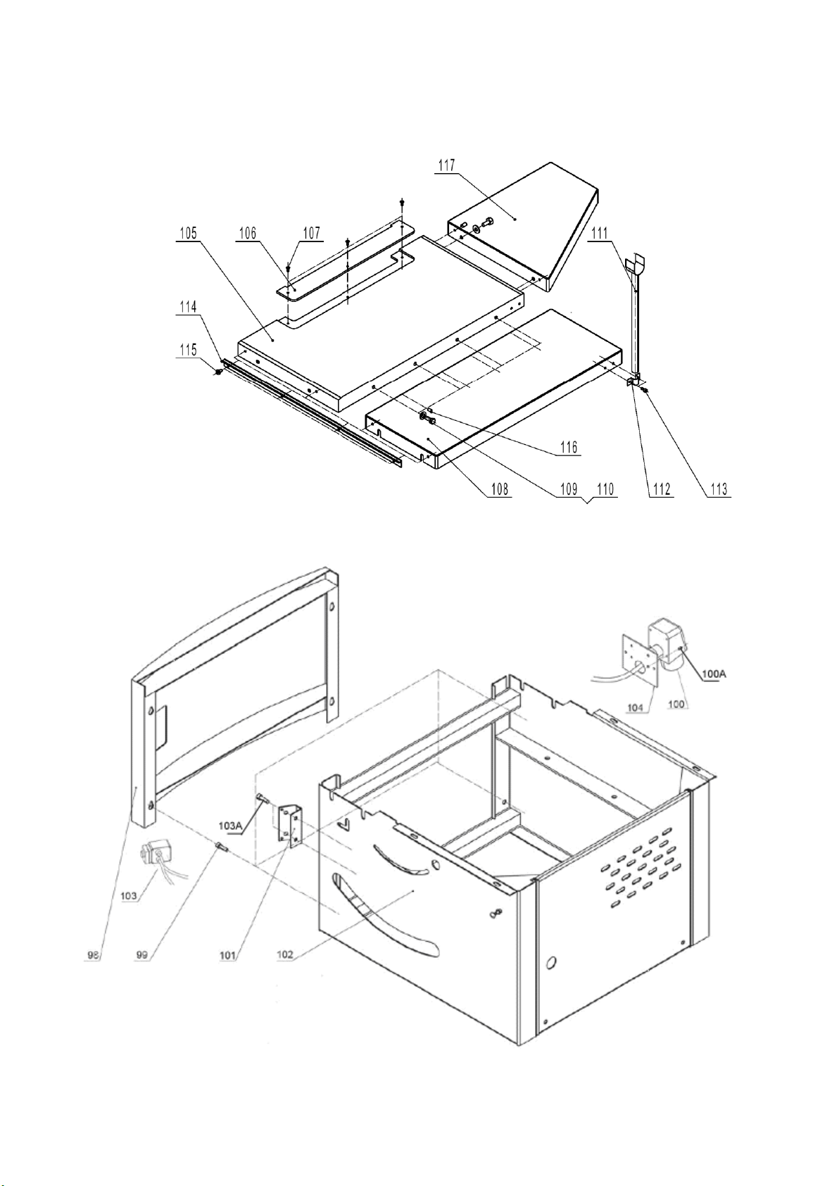
Table and Frame Assembly for JTS-600X
Page 23

Table and Frame Assembly for JTS-600X
Index
Part No.
Description
Size
Qty.
98
JTS600XL-098
Upper acr panel
1 99
JTS600-099
Screw
M6X16
4
100
JTS600-100E
Plug 230V/50Hz/1
1
JTS600-100AE
Plug 400V/50Hz/3
1 100A
JTS600-100A
Screw
M4X15
4
101
JTS600-101
Switch mounting plate
1
102
JTS600-102
Upper frame assembly
1 103
JTS600-103E
Switch Assembly 230V/50Hz/1
1
JTS600-103AE
Switch Assembly 400V/50Hz/3
1 103A
JTS600-103A
Screw
M4X60
2
104
JTS600-104
Plug mounting plate
1
105
JTS600X-105
Main table
1 106
JTS600-106
Table insert
1 107
JTS600-107
Screw
M5x8
3
108
JTS600X-108
Right Extension Table
1
109
JTS600-109
Hex bolt
M8X12
6
110
JTS600-110
Washer
M8
6
111
JTS600-111
Support bracket
1 112
JTS600-112
Semicircular bracket
1 113
JTS600-113
Hex socket screw
M6X16
2
114
JTS600-114
Front rail
1 115
JTS600-115
Pan head screw
M6X16
4
116
JTS600X-116
Hex socket set screw
M6X12
6
117
JTS600X-117
Rear extension table
1
Page 24
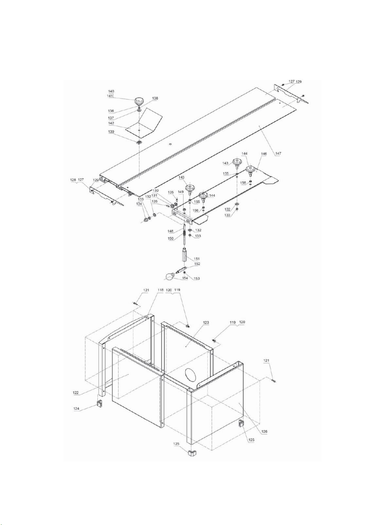
Sliding Table and Cabinet Assembly for JTS-600X
Page 25

Sliding Table and Cabinet Assembly for JTS-600X
Index
Part No.
Description
Size
Qty.
118
JTS600-118
Lower arc panel
1 119
JTS600-119
Nut
M6 8 120
JTS600-120
Washer
M6 8 121
JTS600-121
Hex screw
M6X15
8
122
JTS600-122
Base front panel
1
123
JTS600-123
Base rear panel
1
124
JTS600-124
Foot for arc panel
2 125
JTS600-125
Foot for side panel
2 126
JTS600-126
Base side panel
1 127
JTS600-127
Screw
M5X20
4
128
JTS600-128
Washer
M4
4
129
JTS600-129
Cover for sliding table
2 130
JTS600-130
Carriage bolt
M8X25
4
131
JTS600-131
Washer
M8X25
4
132
JTS600-132
Washer
M10
6
133
JTS600-133
Flange nut
M8
6
134
JTS600-134
Cap nut
M8
4
135
JTS600-135
Hex socket screw
M6X25
4
136
JTS600-136
Hex screw
M6X20
1
137
JTS600-137
Washer
M6 1 138
JTS600-138
Nut
M6 1 139
JTS600-139
Square nut
1
140
JTS600-140
Knob cover
1
141
JTS600-141
Knob body
1 142
JTS600-142
Push plate
1
143
JTS600-143
Bearing tube with eccentric
support
2
144
JTS600-144
Bearing tube with centric support
2
146
JTS600-146
Base support for table
1 147
JTS600-147
Sliding table
1 148
JTS600-148
Position pin
1 149
JTS600-149
Hex thin nut
M12X1.5
1
150
JTS600-150
Spring
1
151
JTS600-151
Position tube
1
152
JTS600-152
Handle rod
1 153
JTS600-153
Nut
M6 1 154
JTS600-154
Handle star knob
1 155
JTS600-155
Thin self locking nut
M8 2 156
JTS600-156
Thin nut
M8
2
Page 26
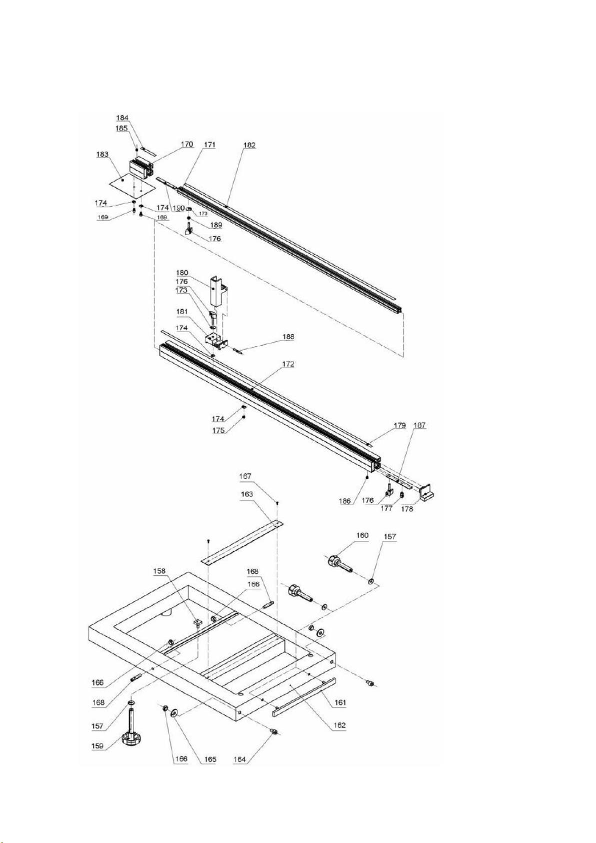
Outriger Table and Pull-out Miter Gauge Assembly for JTS-600X
Page 27

Index
Part No.
Description
Size
Qty.
157
JTS600-157
Washer
M6 7 158
JTS600-158
Locking block
1 159
JTS600-159
Locking handle
1 160
JTS600-160
Locking handle
2 161
JTS600-161
Clamping plate
1
162
JTS600-162
Ext. sliding frame
1
163
JTS600-163
Angle ruler
1 164
JTS600-164
Location screw
2 165
JTS600-165
Washer
M8 2 166
JTS600-166
Hex nut
M8
4
167
JTS600-167
Revit
2
168
JTS600-168
Hex socket nut
M8X40
2
169
JTS600-169
Hex socket screw
M6X12
2
170
JTS600-170
Ext. bracket for lengthened
1
171
JTS600-171
Main bracket for lengthened ruler
1 172
JTS600-172
Fence
1
173
JTS600-173
Washer
M6
2
174
JTS600-174
Square nut
4 175
JTS600-175
Hex socket screw
M6X10
1
176
JTS600-176
Knob
3 177
JTS600-177
Pivot
1 178
JTS600-178
Fence cover
1
179
JTS600-179
Ruler I
1
180
JTS600-180
Location block
1 181
JTS600-181
Sliding block
1 182
JTS600-182
Ruller III
1 183
JTS600-183
Location plate
1
184
JTS600-184
Ruler II
1
185
JTS600-185
Hex socket screw
M5X6
1
186
JTS600-186
Pan head screw
ST4X6
1
187
JTS600-187
Long plate
1 188
JTS600-188
Pin
6x45
1
189
JTS600-189
Tube
1
190
JTS600-190
Fixing plate
1
Outriger Table and Pull-out Miter Gauge Assembly for JTS-600X
Page 28
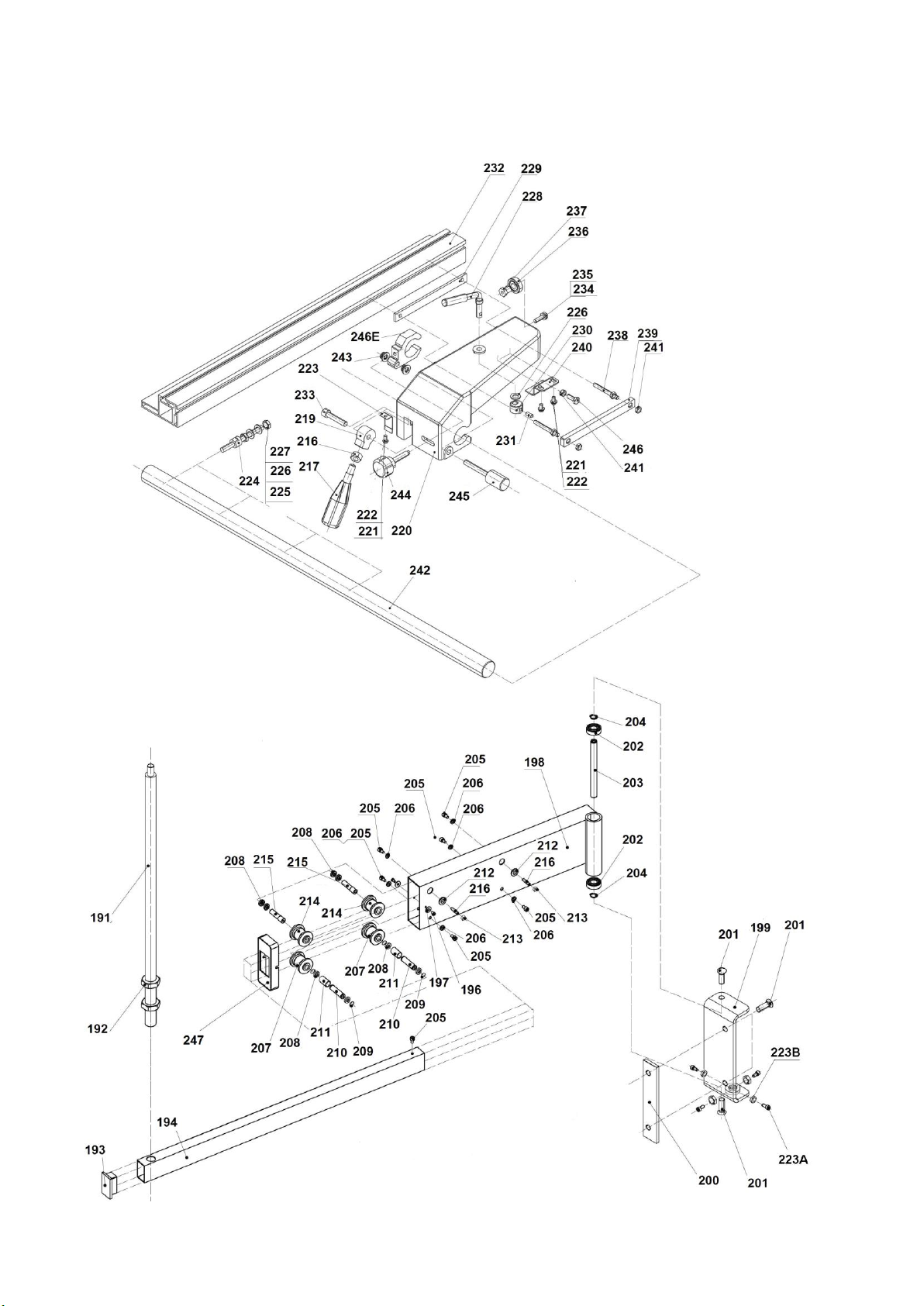
Rip Fence and Swing Arm Assembly for JTS-600X
Page 29

Rip Fence and Swing Arm Assembly for JTS-600X
Index
Part No.
Description
Size
Qty.
191
JTS600-191
Support rod
1 192
JTS600-192
Nut
M20
2
193
JTS600-193
Tube cap
2 194
JTS600-194
Telescopic tube
1 195
JTS600-195
End cover
1
196
JTS600-196
Screw
M4X8
2
197
JTS600-197
Washer
M5 2 198
JTS600-198
Support for telescopic tube
1 199
JTS600-199
Fixing bracket
1 200
JTS600-200
Connection plate
1
201
JTS600-201
Hex socket screw
M10X25
4
202
JTS600-202
Bearing
6202-RZ
2
203
JTS600-203
Shaft
1 204
JTS600-204
Clip ring
M15
2
205
JTS600-205
Screw
M6X10
7
206
JTS600-206
Washer
M6
6
207
JTS600-207
Lower wheel
2
208
JTS600-208
Bearing
61801-RZ
8
209
JTS600-209
Clip ring
M12
4
210
JTS600-210
Shaft
2 211
JTS600-211
Tube
2 212
JTS600-212
Outside baffle
2
213
JTS600-213
Nut
M6
2
214
JTS600-214
Upper wheel
2 215
JTS600-215
Eccentric shaft
2 216
JTS600-216
Hex socket screw
M6X25
2
217
JTS600-217
Locking handle
1
218
JTS600-218
Nut
M10
1
219
JTS600-219
Cam
1
219A
JTS600-219A
Cam & handle assembly(#217,
Thu 219)
1
223A
JTS600-223A
Screw
M6X30
4
223B
JTS600-223B
Nut
M6
4
Page 30

Rip Fence and Swing Arm Assembly for JTS-600X
Index
Part No.
Description
Size
Qty.
220
JTS600-220
Rip fence bracket
1 221
JTS600-221
Screw
M5X8
3
222
JTS600-222
Washer
M5X8
3
223
JTS600-223
Clip spring
1 224
JTS600-224
Stud
4
225
JTS600-225
Nut
M8
4
226
JTS600-226
Washer
M8 9 227
JTS600-227
Nut
M8 4 228
JTS600-228
Handle
1 229
JTS600-229
Locking plate I
1
230
JTS600-230
Locking cam wheel
1
231
JTS600-231
Hex socket srcew
M8X18
1
232
JTS600-232
L-shape rip fence
1 233
JTS600-233
Hex socket srcew
M8X40
1
234
JTS600-234
Hex screw
M6X20
1
235
JTS600-235
Washer
M6
1
236
JTS600-236
Bearing
6000-RZ
1
237
JTS600-237
Bearing bracket
1 238
JTS600-238
Locking screw
2 239
JTS600-239
Locking plate II
1 240
JTS600-240
Support plate
1 241
JTS600-241
Hex nut
M6
5
242
JTS600-242
Fence bracket rail
1
243
JTS600-243
Self locking nut
M8 2 244
JTS600-244
Star locking handle
1 245
JTS600-245
Micro adjust handle
1 246
JTS600-246
Hex screw
M6X16
1
246E
JTS600-246E
Clamping bracket
1
247
JTS600-247
Insert, Swing Arm
1
Page 31
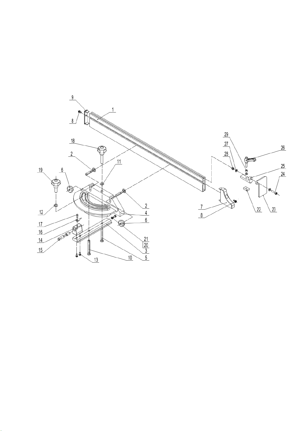
Mitre Gauge Assembly for JTS-600X------Optional Accessory
Stock Number: 10000073
Page 32
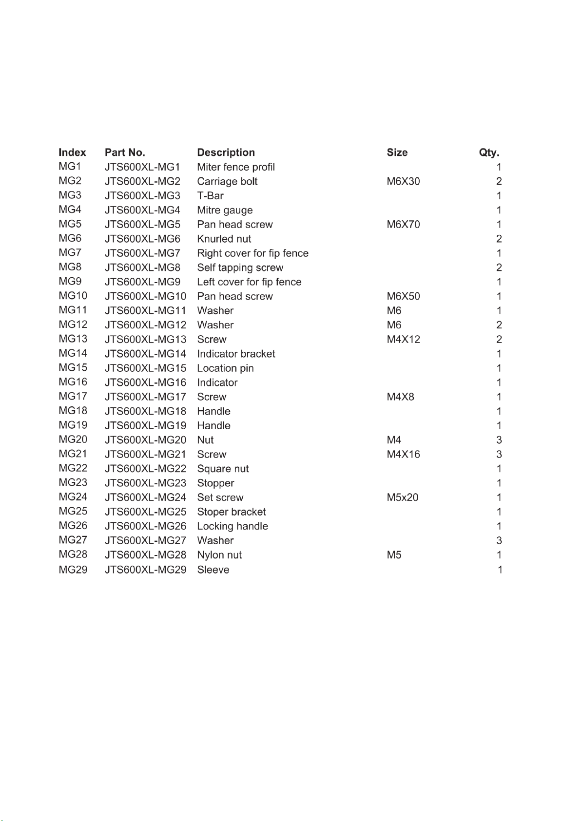
Miter Gauge Assembly for JTS-600X------Optional Accessory
Stock Number: 10000073
Page 33
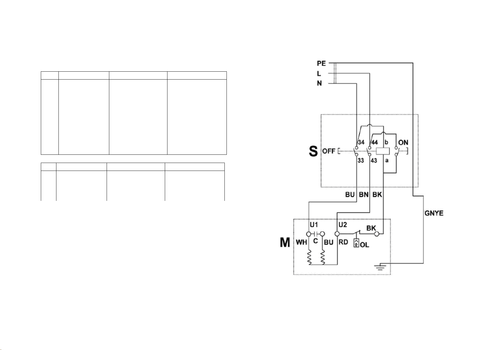
JTS-600X
colour of strands
Litzenfarben
couleur des cordons
BK
black
schwarz
noir
WH
white
weiß
blanc
BU
blue
blau
bleu
YE
yellow
gelb
jaune
RD
red
rot
rouge
BN
brown
braun
brun
GY
grey
grau
gris
GNYE
green-yellow
grün-gelb
vert-jaune
OG
orange
orange
orange
VT
violet
violett
violet
meaning of symbol
Bedeutung der Zeichen
interprétation
M
motor
Motor
moteur
S
switch
Schalter
interrupteur
C
condenser
Kondensator
condensateur
OL
overload cut-off
Überlastschutzschalter
déclencheur surcharge
10000060XM
230/50/1
Page 34
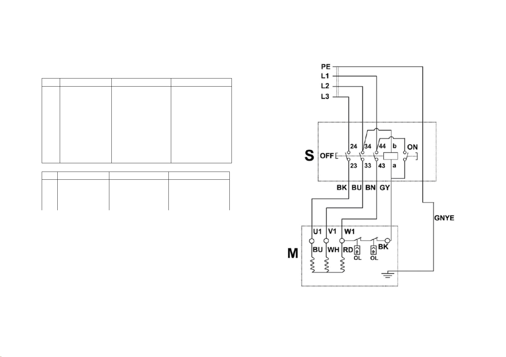
colour of strands
Litzenfarben
couleur des cordons
BK
black
schwarz
noir
WH
white
weiß
blanc
BU
blue
blau
bleu
YE
yellow
gelb
jaune
RD
red
rot
rouge
BN
brown
braun
brun
GY
grey
grau
gris
GNYE
green-yellow
grün-gelb
vert-jaune
OG
orange
orange
orange
VT
violet
violett
violet
meaning of symbol
Bedeutung der Zeichen
interprétation
M
motor
Motor
moteur
S
switch
Schalter
interrupteur
C
condenser
Kondensator
condensateur
OL
overload cut-off
Überlastschutzschalter
déclencheur surcharge
JTS-600X
10000060XT
400/50/3
Page 35
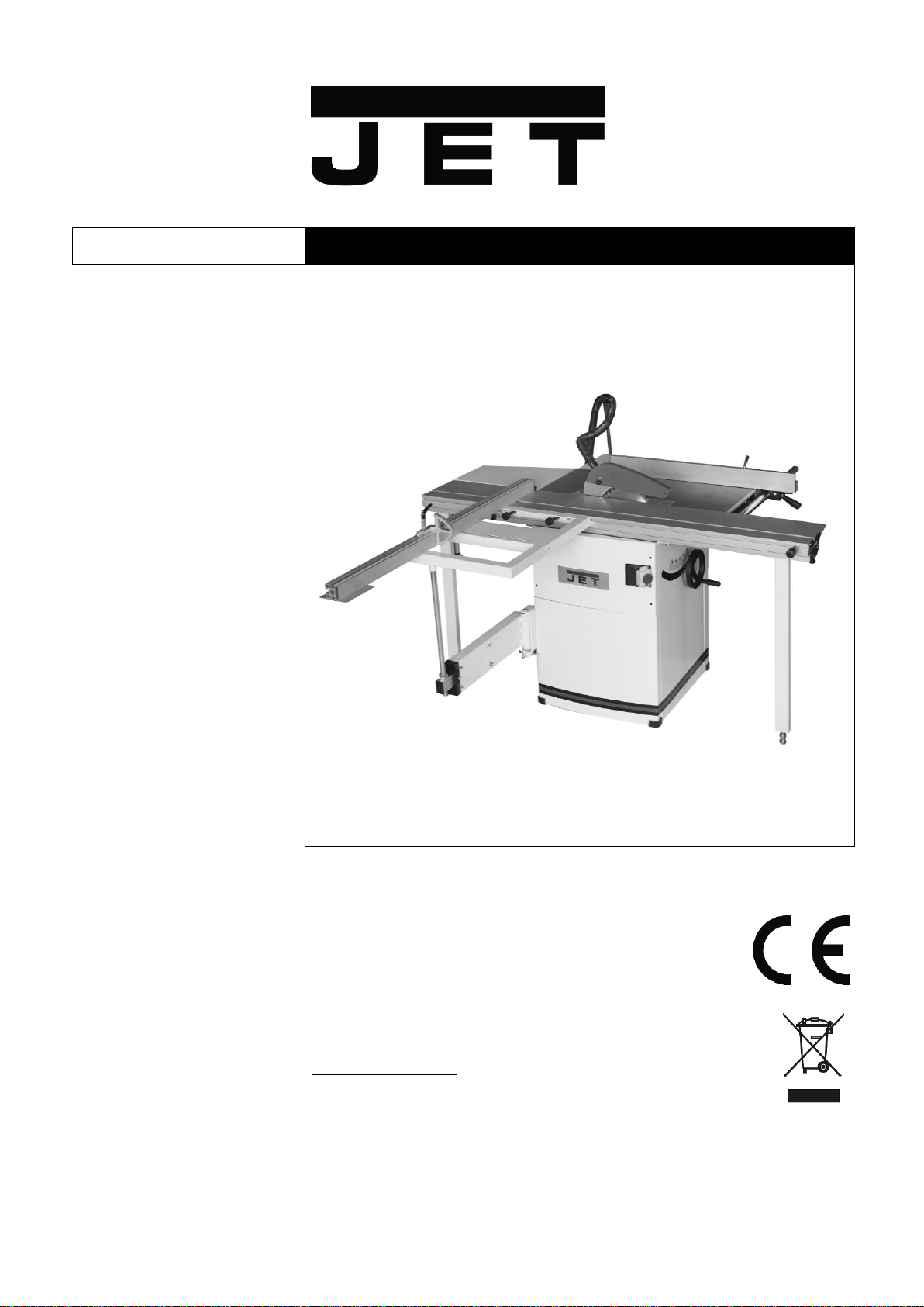
JTS-600XL
CIRCULAR SAW BENCH
Original Language:
GB
Operating Instructions
Translations:
D
Gebrauchsanleitung
F
Mode d´emploi
JPW (Tool) AG
Tämperlistrasse 5
CH-8117 Fällanden
Switzerland
Phone +41 44 806 47 48
Fax +41 44 806 47 58
www.jettools.com
M - 10000070XLM,10000070XLT 2016-03
Page 36
CE-Conformity Declaration
Product: Circular Saw Bench
JTS-600XL-M
Stock Number: 10000070XLM
JTS-600XL-T
Stock Number: 10000070XLT
Brand: JET
Manufacturer:
JPW (Tool) AG, Tämperlistrasse 5, CH-8117 Fällanden, Switzerland
On our own responsibility we hereby declare that this product complies with the regulations
* 2006/42/EC Machinery Directive
* 2004/108/EC EMC Directive (Electro Magnetic Compatibility)
* 2006/95/EC Low Voltage Directive
* 2011/65/EU RoHS Directive (Reduction of Hazardous Substances)
designed in consideration of the standards
** EN 1870-1, EN60204-1, EN61000-6-2,EN61000-6-4, EN ISO 12100
CE type examination
*** BM 50280872 0001,
performed by
**** TÜV Rheinland Product Safety GmbH,
Am Grauen Stein, DE-51105 Köln (notified body No 0197).
Technical file compiled by: Alain Schmid, JPW (TOOL) AG, General Manager
2016-03-06 Alain Schmid, General Manager
JPW (Tool) AG, Tämperlistrasse 5, CH-8117 Fällanden, Switzerland
2
Page 37

GB - ENGLISH
Operating Instructions
Dear Customer,
Many thanks for the confidence you have shown in us with the purchase of your new JET-machine. This manual has been
prepared for the owner and operators of a JET JTS-600XL table saw to promote safety during installation, operation and
maintenance procedures. Please read and understand the information contained in these operating instructions and the
accompanying documents. To obtain maximum life and efficiency from your machine, and to use the machine safely, read this
manual thoroughly and follow instructions carefully.
…Table of Contents
1. Declaration of conformity
2. Warranty
3. Safety
Authorized use
General safety notes
Remaining hazards
4. Machine specifications
Technical data
Noise emission
Dust emission
Contents of delivery
Description of machine
5. Transport and start up
Transport and installation
Assembly
Dust connection
Mains connection
Starting operation
6. Machine operation
7. Setup and adjustments
Changing saw blade
Mounting the raving knife
Mounting the saw guard
Rising and tilting saw blade
Sliding table setup
Rip fence setup
Sawblade tilting
8. Maintenance and inspection
9. Troubleshooting
10. Environmental protection
11. Available accessories
12. „Safe operation” ........ appendix A
1. Declaration of conformity
On our own responsibility we hereby
declare that this product complies with
the regulations* listed on page 2.
Designed in consideration with the
standards**.
CE type examination*** performed
by****.
2. Warranty
The Seller guarantees that the
supplied product is free from material
defects and manufacturing faults. This
warranty does not cover any defects
which are caused, either directly or
indirectly, by incorrect use,
carelessness, accidental damage,
repair, inadequate maintenance or
cleaning and normal wear and tear.
Guarantee and/or warranty claims
must be made within twelve months
from the date of purchase (date of
invoice). Any further claims shall be
excluded.
This warranty includes all guarantee
obligations of the Seller and replaces
all previous declarations and
agreements concerning warranties.
The warranty period is valid for eight
hours of daily use. If this is exceeded,
the warranty period shall be reduced
in proportion to the excess use, but to
no less than three months.
Returning rejected goods requires the
prior express consent of the Seller and
is at the Buyer’s risk and expense.
Further warranty details can be found
in the General Terms and Conditions
(GTC). The GTC can be viewed at
www.jettools.com or can be sent by
post upon request.
The Seller reserves the right to make
changes to the product and
accessories at any time.
3. Safety
3.1 Authorized use
3
This machine is designed for sawing
wood, wood derived materials as well
as similar to be machined hard
plastics only.
Machining of other materials is not
permitted and may be carried out in
specific cases only after consulting
with the manufacturer.
No metal workpieces may be
machined.
The workpiece must allow to safely be
loaded, supported and guided.
No cuts without using the rip fence,
the 90° fence or the sliding table may
be performed.
No submerged cuts by removing the
riving knife and/or saw guard may be
performed.
The use of a power feeder is not
considered.
The proper use also includes
compliance with the operating and
maintenance instructions given in this
manual.
The machine must be operated only
by persons familiar with its operation,
maintenance and repair and who are
familiar with its hazards.
The required minimum age must be
observed.
The machine must only be used in a
technically perfect condition.
When working on the machine, all
safety mechanisms and covers must
be mounted.
In addition to the safety requirements
contained in this operating instruction
and your country’s applicable
regulations, you should observe the
generally recognized technical rules
concerning the operation of
woodworking machines.
Page 38

Any other use exceeds authorization.
In the event of unauthorized use of the
machine, the manufacturer renounces
all liability and the responsibility is
transferred exclusively to the operator.
3.2 General safety notes
Woodworking machines can be
dangerous if not used properly.
Therefore the appropriate general
technical rules as well as the following
notes must be observed.
Read and understand the entire
instruction manual before attempting
assembly or operation.
Keep this operating instruction close
by the machine, protected from dirt
and humidity, and pass it over to the
new owner if you part with the tool.
No changes to the machine may be
made.
Daily inspect the function and
existence of the safety appliances
before you start the machine.
Do not attempt operations in this case,
protect the machine by unplugging the
mains cord.
Remove all loose clothing and confine
long hair.
Before operating the machine, remove
tie, rings, watches, other jewellery, and
roll up sleeves above the elbows.
Wear safety shoes; never wear leisure
shoes or sandals.
Always wear the approved working
outfit :
- safety goggles
- ear protection
- dust protection
Do not wear gloves while operating
this machine.
For the safe handling of sawblades
wear work gloves.
Observe the chapter “save operation”
in this manual.
Check the correct rotation of the
sawblade before operating the
machine.
Do not start cutting operation until
sawblade is at full speed.
Control the stopping time of the
machine, it may not be longer than 10
seconds.
Do not use side pressure to stop
rotating blade.
Insure that the workpiece does not roll
when cutting round pieces.
Use suitable table extensions and
supporting aids for difficult to handle
workpieces.
Always hold and guide the workpieces
safely during machining.
Pay particular attention to instructions
on reducing the risk of kickback.
The supplied raving knife must always
be used. Adjust the space to the
sawblade to be between 2 to 5mm.
Do not perform any operation
freehand.
Never reach around or over the saw
blade.
When ripping narrow workpieces
(<120mm) use as push-stick or pushwood.
Always use crossfeed guide for cutting
off.
The use of dado-blades is not
permissible.
Make sure that small cut off
workpieces will not be caught and
thrown away by the rising saw blade
teeth.
Take care when slotting.
Remove cut and jammed workpieces
only when motor is turned off and the
machine is at a complete standstill.
Install the machine so that there is
sufficient space for safe operation and
workpiece handling.
Keep work area well lighted.
The machine is designed to operate in
closed rooms and must be placed
stable on firm and levelled ground.
Make sure that the power cord does
not impede work and cause people to
trip.
Keep the floor around the machine
clean and free of scrap material, oil
and grease.
Stay alert!
Give your work undivided attention.
Use common sense.
Keep an ergonomic body position.
Maintain a balanced stance at all
times.
Do not operate the machine when you
are tired.
Do not operate the machine under the
influence of drugs, alcohol or any
medication. Be aware that medication
can change your behaviour.
Keep children and visitors a safe
distance from the work area.
Never reach into the machine while it
is operating or running down.
Never leave a running machine
unattended. Before you leave the
workplace switch off the machine.
Do not operate the electric tool near
inflammable liquids or gases.
Observe the fire fighting and fire alert
options, for example the fire
extinguisher operation and place.
Do not use the machine in a dump
environment and do not expose it to
rain.
Wood dust is explosive and can also
represent a risk to health.
Dust form some tropical woods in
particular, and from hardwoods like
beach and oak, is classified as a
carcinogenic substance.
Always use a suitable dust extraction
device
Before machining, remove any nails
and other foreign bodies from the
workpiece.
Specifications regarding the maximum
or minimum size of the workpiece
must be observed.
Do not remove chips and workpiece
parts until the machine is at a
complete standstill.
Never operate with the guards not in
place – serious risk of injury!
Do not stand on the machine.
Connection and repair work on the
electrical installation may be carried
out by a qualified electrician only.
Always unwind any extension cords
fully.
Have a damaged or worn cord
replaced immediately.
Do not use the machine when the ONOFF switch does not operate correctly.
Make all machine adjustments or
maintenance with the machine
unplugged from the power source.
Use only sawblades according to
EN 847-1.
Never use sawblades made from High
Speed Steel (HSS).
Take care that the selection of the saw
blade depends on the material to be
cut.
Remove defective sawblades
immediately.
A worn table insert must be replaced.
4
Page 39
3.3 Remaining hazards
When using the machine according to
regulations some remaining hazards
may still exist
The moving sawblade in the work area
can cause injury.
Broken saw blades can cause injuries.
Thrown workpieces can lead to injury
Tipping of the workpiece due to
insufficient support can lead to injury.
Wood chips and sawdust can be
health hazards. Be sure to wear
personal protection gear such as
safety goggles ear- and dust
protection.
Use a suitable dust exhaust system.
The use of incorrect mains supply or a
damaged power cord can lead to
injuries caused by electricity.
The type and condition of the
sawblade is important in keeping the
noise level as low as possible.
This does not negate the fact that
extra safety equipment such as ear
protection must be used.
4. Machine specifications
4.1 Technical data
Machine Table 800x350 mm
Right extension table 800x270 mm
Rear extension table 415x350mm
Sliding table size 1600x240 mm
Max. travel of sliding table 1700 mm
Max. length of cut 1600 mm
Sawblade diameter max 250 mm
Blade bore diameter 30 mm
Blade speed n0 4000 rpm
Cutting height at 90°/45° 80/54 mm
Tilting range of blade 90°- 45°
Max. width of rip cut 610 mm
Dust port diameter 100mm
Weight 170 kg
Mains ~230V, L/N/PE, 50Hz
Motor output power 1,5kW (2HP) S1
Reference current 9.6 A
Extension cord (H07RN-F): 3x1,5mm²
Installation fuse protection 16A
Mains ~400V, 3L/PE, 50Hz
Motor output power 1,5 kW (2 HP) S1
Reference current 4.7 A
Extension cord (H07RN-F): 4x1,5mm²
Installation fuse protection 16A
4.2 Noise emission
Determined according to EN 1870-1
(Inspection tolerance 4 dB)
Workpiece plywood 16mm:
Acoustic power level
(according to EN ISO 3746):
Idling LwA 98,2 dB (A)
Operating LwA 101,8 dB (A)
Acoustic pressure level
(according to EN ISO 11202):
Idling LpA 84,2 dB (A)
Operating LpA 88,5 dB (A)
The specified values are emission
levels and are not necessarily to be
seen as safe operating levels.
This information is intended to allow
the user to make a better estimation of
the hazards and risks involved.
4.3 Dust emission
The circular saw has been dust
emission evaluated.
At an air velocity of 20m/sec on the
dust port dia. 100mm:
Vacuum pressure 850Pa
Volume flow 565 m³/h
The TRK-value of 2 mg/m3 is not
exceeded.
4.4 Content of delivery
Machine stand
Sliding table
Sliding table support legs
Crosscut table
Crosscut fence
Telescopic arm
Rare extension table
Right extension table
Rip fence with dual fence profile
Rip fence support bar
Saw guard
Sawblade 250mm
Dust connection hose and Y-adapter
Hose tye
Push stick
Operating tools
Assembly bag
Operating manual
Spare parts list
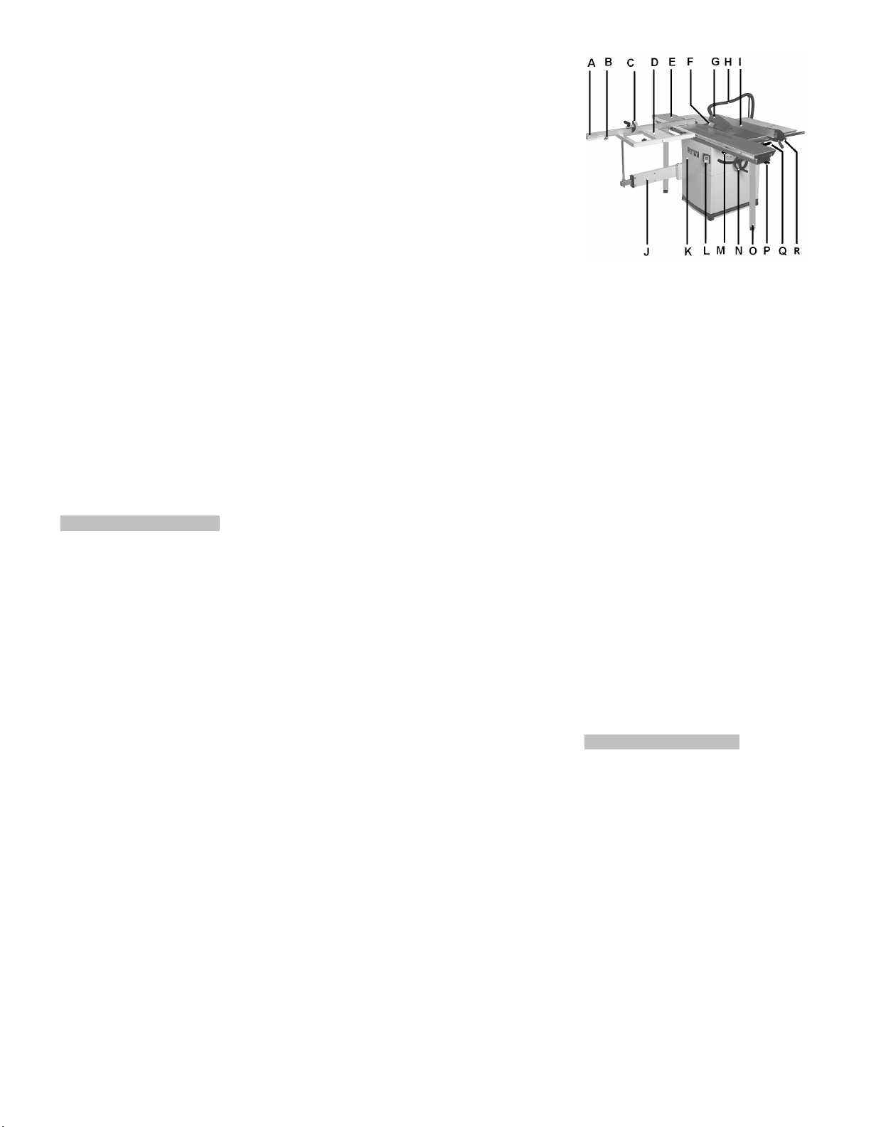
4.5 Description of machine
Fig 1
A…...Crosscut fence
B…..Pull out lock knob
C….Crosscut stop
D…..Crosscut table
E…..Sliding table
F…..Raving knife
G…..Saw guard
H….Dust connection hose
I…..Rip fence
J…...Telescopic arm
K….Front cabinet cover
L….On/ Off switch
M….Blade tilt lock
N….Blade rise handwheel
O….Sliding table support leg
P….Sliding table lock
Q….Blade tilt handwheel
R….Rip fence micro adjustment
5. Transport and start up
5.1 Transport and installation
For transport to the desired location
use a forklift or hand trolley. Make
sure the machine does not tip or fall
off during transport.
The machine is designed to operate in
closed rooms and must be placed
stable on firm and levelled ground.
The machine must be levelled in both
directions to assure good sliding
motion of the sliding table.
If possible, the machine must be
placed on rubber plates which act as
shock absorbers and reduce the noise
level.
For packing reasons the machine is
not completely assembled.
5
Page 40
5.2 Assembly
If you notice any transport damage
while unpacking, notify your supplier
immediately. Do not operate the
machine!
Dispose of the packing in an
environmentally friendly manner.
Clean all rust protected surfaces with
a mild solvent.
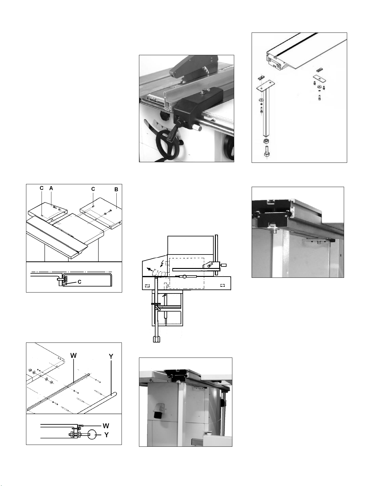
Mounting table extensions
Attach rear extension table (A, Fig 2)
to the machine table with hex head
screws and washers.
Attach right extension table (B) to the
machine table with hex head screws
and washers.
Put table surfaces in level to the main
table.
Use the rip fence profile to check and
the grub screws (C) to adjust.
Mount the scale carrier (W).
Mounting rip fence
Mount the rip fence to the rip fence
support bar.
Fig 4
The rip fence must be guided parallel
to the table surface. Adjust the round
bar (Y) up-down as needed.
Fig 6
Fig 7
Fig 2
Mounting rip fence support bar
Mount the rip fence support bar (Y, Fig
3) to the front of the saw table and
right table extension.
Mounting sliding table:
With the help of another person, lift
the sliding table carefully to its place
and attach (see Fig 5,6, 7 and 8).
Fig 5
Fig 8
Attach the sliding table support legs.
Sliding Table Adjustment:
The sliding table is adjusted ex works.
The sliding table must be aligned to
run parallel to the sawblade
The table surface must be 0,1 - 0,4
mm higher than the machine table.
Use rip fence profile to check (Fig 9).
Fig 3
6
Page 41
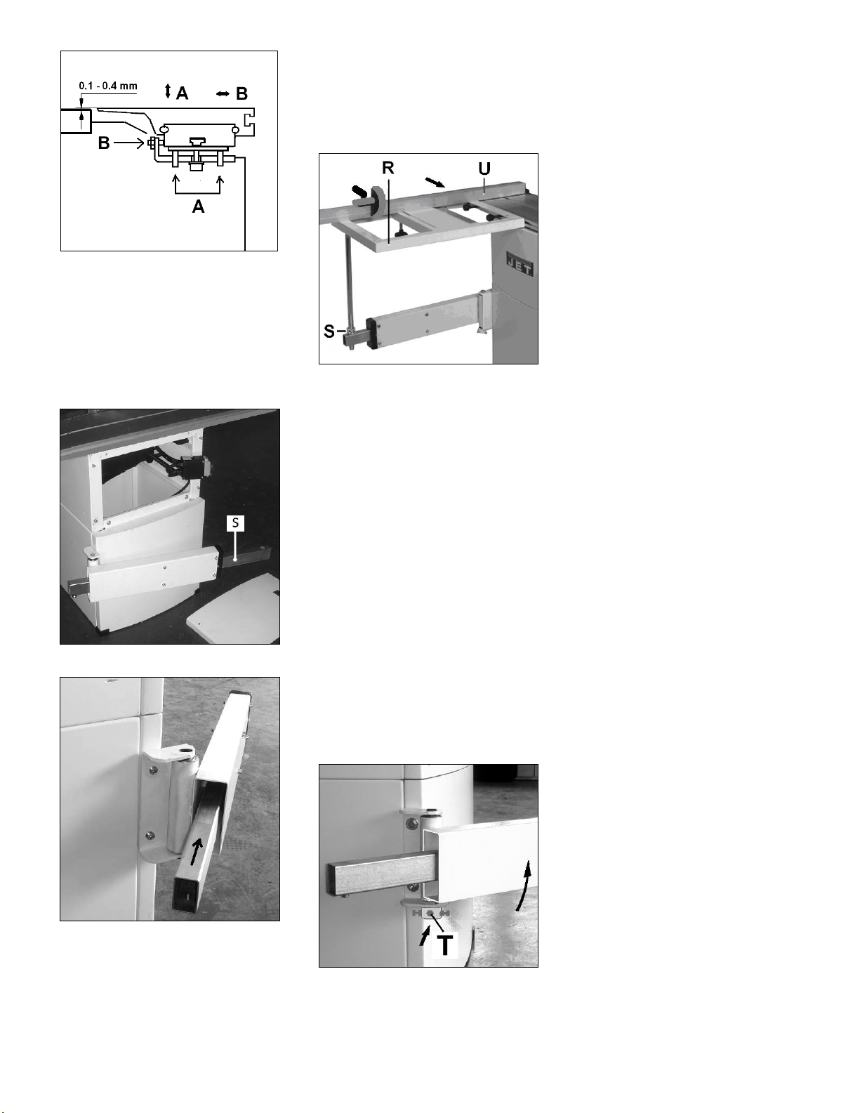
Fig 9
Adjustment:
The sliding table guide assembly can
be adjusted up-down and parallel to
the sawblade.
Use the grub screws (A & B) to adjust.
Mounting telescopic arm:
Insert the beam (S, Fig 10, Fig 11) into
the telescopic arm
Fig 10
Fig 11
Crosscut table setup
Crosscut table setup shall never be
performed when the machine is
running.
Lift the crosscut table (R, Fig 12) onto
telescopic arm and slide onto sliding
table T-groove and lock in place).
Fig 12
Crosscut table and telescopic arm are
rough aligned ex works (The table
surface must be in level with the
sliding table).
Telescopic arm adjustment:
The telescopic arm is adjusted ex
works.
For correction, move the sliding table
so that telescopic arm reaches out
straight (like shown in Fig 12)
Align the crosscut table height with the
two hex nuts (S).
Use crosscut fence profile (U) to
check.
Move the sliding table forward.
For example: if the crosscut table falls,
tighten the left adjust screw (T, Fig 13)
until the crosscut table does not move
in height during sliding table travel.
Loosen and tighten the adjust screws
and lock nuts as needed.
Fig 13
Finish alignment by setting crosscut
table and machine table in level with
nuts (S).
Lock the two nuts (S, Fig 12) against
each other.
Start the machine with care.
Crosscut fence setup:
Crosscut fence (U, Fig 12) setup shall
never be performed when the machine
is running.
The cross-cut table has 2 precision
holes, allowing the crosscut fence to
be put in 2 positions:
At the back and front of the crosscut
table.
Simply put the fence onto the crosscut table and lock it in position using
the supplied knobs.
The 90° adjustable stops (R, Fig 12)
are factory set.
The fence scale is factory set.
Adjustment can be made by moving
the pivot point along the T-grove.
Confirm by test cuts.
When, after some time, the plastic
protection cap at the front on the
cross-cut fence is cut away, a new one
has to be installed
(part no.: JTS600-178).
Mounting Sawblade
See chapter 7.1
Adjusting Raving Knife
See chapter 7.2
Mounting Saw Guard
See chapter 7.3
5.3 Dust connection
Before initial operation, the machine
must be connected to a dust extractor.
The suction should switch on
automatically when the saw is
switched on.
A connecting hose, a hose support, a
Y-piece and a hose tye are supplied
with the machine.
Mounting Hose Support:
Attach the hose support (AA, Fig 14)
to the table extension with the
supplied fastening clip.
7
Page 42
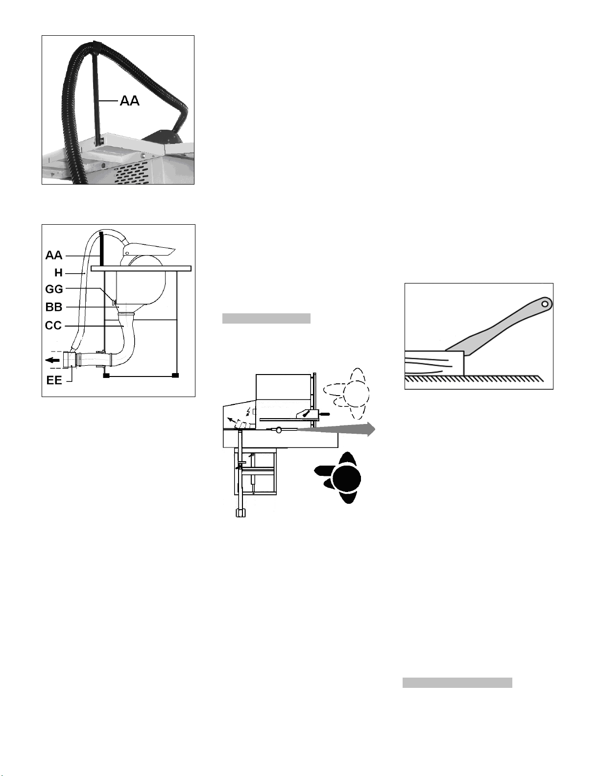
Attention:
-Check first if the saw spindle runs
freely and if all safety devices are
fitted before starting the machine.
For safety reasons this must only be
done without the sawblade installed!
- If the direction of rotation is not
correct, the phase converter inside the
CCE Euro plug must be pushed in and
turned 180°.
(Clockwise direction of the spindle is
correct).
Fig 14
5.5 Starting operation
You can start the machine with the
green On-button. The red Off-button
stops the machine.
In case of machine overload the motor
overload cut-off will react.
After appr.10 min of cooling the
machine can be started again.
6. Machine operation
Correct working position:
In front of the machine standing out of
the line of cutting (danger zone).
Operating hints:
Work only with a sharp and flawless
sawblade.
Take care that the selection of the saw
blade depends on the material to be
cut.
Use a suitable wedge to prevent round
timber from turning under the pressure
of the cut.
Use suitable table extensions and
supporting aids for difficult to handle
workpieces.
Always hold and guide the workpieces
safely during machining.
Do not perform any operation
freehand.
Take care when slotting.
When ripping narrow workpieces
(<120mm) use as push-stick or pushwood.
Fig 15
Mount the Y-piece (EE) and the
connecting hose (H) for the upper dust
collection.
The flow rate on the suction port dia.
100mm must be 20m/sec.
Flexible hoses must be of nonflammable quality, and must be
connected to the machine ground
system.
5.4 Mains connection
Mains connection and any extension
cords used must comply with
applicable regulations.
The mains voltage must comply with
the information on the machine licence
plate.
The mains connection must have a
16A surge-proof fuse.
Only use connection cables marked
H07RN-F
Connections and repairs to the
electrical equipment may only be
carried out by qualified electricians.
Fig 16
Workpiece handling:
Hands placed flat on the workpiece
outside the cutting area.
Feed the workpiece towards the saw
blade in the direction of the saw line.
Push the workpiece steadily forward;
complete the cut as a single
movement.
Support long and wide workpieces
with helping roller stands.
The use of a power feeder is not
considered.
Fig 17
Make sure that small cut off
workpieces will not be caught and
thrown away by the rising saw blade
teeth.
Remove cut and jammed workpieces
only when motor is turned off and the
machine is at a complete standstill.
Pay particular attention on reducing
the risk of kickback.
The supplied raving knife must always
be used.
For the authorized use of the
machine observe the appendix A
“safe operation“
(on the last pages of this operating
manual)
A.1.: Ripping
A.2.: Ripping of narrow stock
A.3.: Crosscutting on rip fence
A.4.: Use of push wood handle
7. Setup and adjustments
8
Page 43
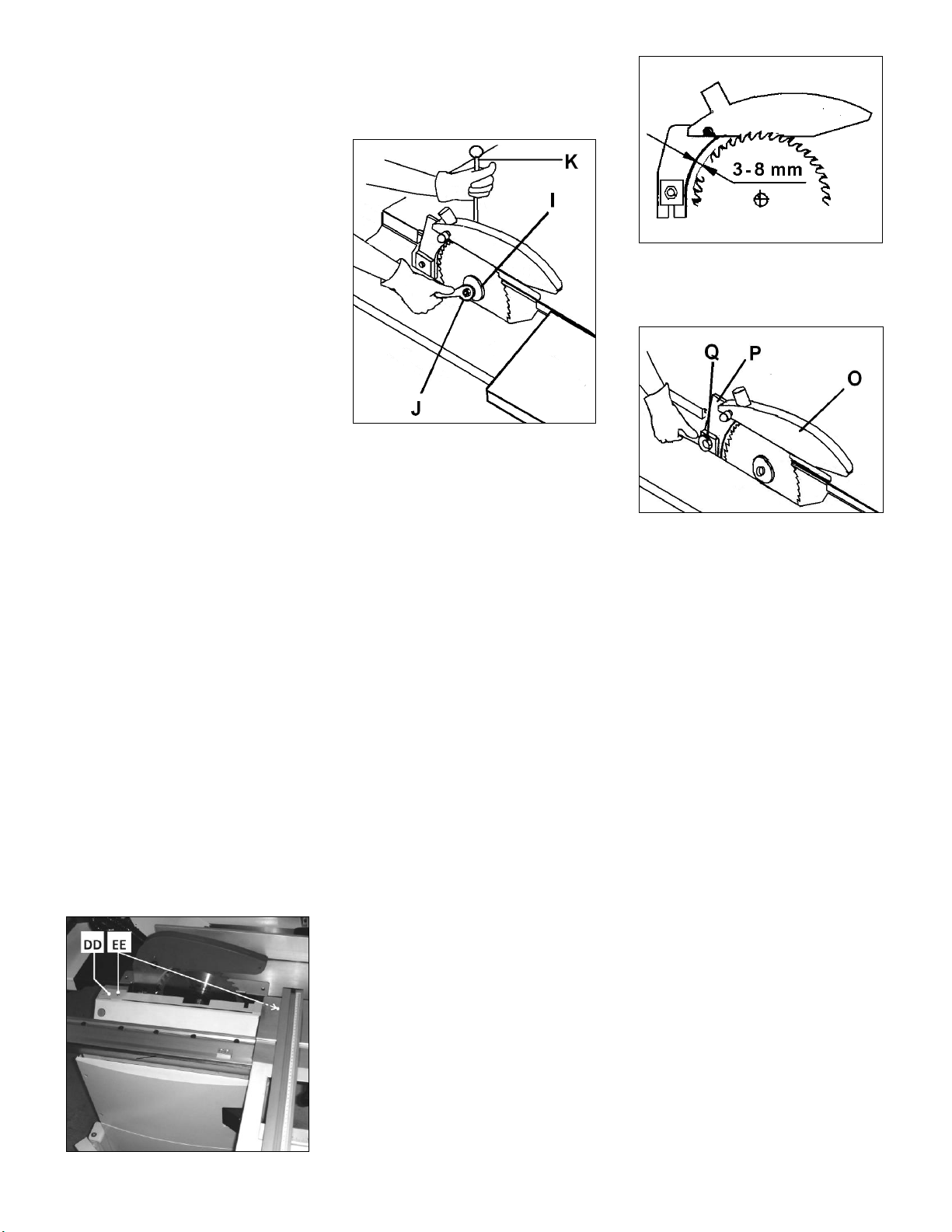
General note:
Setup and adjustment work may
only be carried out after the
machine is protected against
accidental starting by pulling the
mains plug.
7.1 Changing sawblade
The sawblade has to meet the
technical specification.
Use only sawblades according to EN
847-1
The maximum diameter of the saw
blades used on the machine is 250
mm.
Check sawblade for flaws (cracks,
broken teeth, bending) before
installation. Do not use faulty
sawblades.
Warning:
The use off HSS saw blades is
prohibited; use only carbide tipped
saw blades.
The sawblade teeth must point in
cutting direction (down)
Always wear suitable gloves when
handling sawblades.
WARNING:
When installing or changing saw
blade, always disconnect saw from
power source, unplug!
Remove the crosscut table.
Remove the sliding table.
Raise the main sawblade to its highest
position.
Remove the saw guard.
Changing saw blade:
Move the sliding table to the end to get
access to the sawblade.
Loosen the 2 screws (EE, Fig18) and
remove the sheetmetal protective
cover (DD).
Fig 18
Loosen the arbor nut (J, Fig 19) while
stopping the arbor against rotation
with the locking pin (K).
Fig 19
Attention: left hand thread.
Remove the arbor nut (J) and flange
(I).
Place saw blade on arbor shaft
making sure teeth point down at the
front of the saw.
Reinstall flange, washer and arbor nut
and securely tighten.
Remove the locking pin (K).
Check the correct position of the
raving knife in regards to the saw
blade (see Chapter 7.2).
Reinstall the saw guard and the
protective cover (DD).
7.2 Mounting the raving knife
The supplied raving knife must always
be used.
The machine is equipped with a raving
knife for the use of sawblades
diameter 250 mm.
The raving knife has to be adjusted in
such a way that over its entire length
the gap between sawblade and raving
knife does not exceed min. 3 mm and
max. 8 mm (Fig 20).
Fig 20
The raving knife (P, Fig 21) can be
adjusted in both vertical and horizontal
direction.
Fig 21
The height setting has to be adjusted
in such a way that the sawguard
bottom never exceeds more than 3
mm above the highest placed
sawblade tooth.
After height adjustment always locks
the central bolt (Q).
Never remove this raving knife.
Kickbacks are severe and very
dangerous.
No submerged cuts by removing the
raving knife and/or saw guard may be
performed.
7.3 Mounting the saw guard
The sawguard (O, Fig 21) must always
be used.
Attach the saw guard to the raving
knife (P).
The sawguard must be lowered to the
workpiece to minimise the amount of
exposed teeth.
Adjustment shall never be performed
when the machine is running.
The saw guard has to be connected to
the dust extractor system.
7.4 Rising and tilting sawblade
9
Page 44
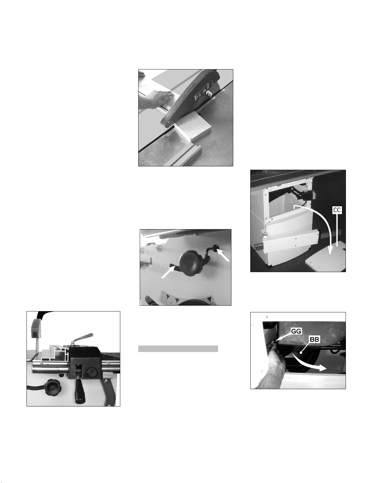
Setup adjustments of the sawblade
shall never be performed when the
machine is running.
Use the front hand wheel to raise the
sawblade (one turn of the handwheel
equals to approximately 3 mm of
height setting).
Use the right hand wheel to tilt the
sawblade.
Both 45° and 90° positive stops are
factory set.
Start the machine with care.
7.5 Sliding table setup
Sliding table setup shall never be
performed when the machine is
running.
When loading panels and when rip
cutting the sliding table must be
locked.
It is recommended to clean the sliding
table once a week, and to remove all
sawdust and chips which gradually
slow down the sliding table.
Never use oil or grease!
7.6 Rip fence setup
Rip fence setup shall never be
performed when the machine is
running.
Note:
The rip fence profile can be placed flat
and adjusted in length.
-The cutting of small work pieces
(width less than 120mm) shall only be
performed with the rip fence profile
placed flat (Fig 22).
Fig 22
When cross cutting using the rip
fence, to avoid the wood getting stuck
between the fence and the riving knife
(resulting in a highly dangerous
kickback) it is necessary to position
the fence so that its end corresponds
with the front of the sawblade (Fig 23).
Fig 23
Start the machine with precaution.
7.7 Blade tilt 45° and 90° positive
stop adjustment
The blade tilt positive stops can be
adjusted with an allen key (Fig 24).
Fig 24
8. Maintenance and inspection
General notes:
Maintenance, cleaning and repair
work may only be carried out after
the machine is protected against
accidental starting by pulling the
mains plug.
Repair and maintenance work on the
electrical system may only be carried
out by a qualified electrician.
Inspect the proper function of the dust
extraction daily.
Keep the inside of the cabinet clear of
sawdust and wood chips. Make sure
the motor fan and fan cover are also
kept clear of sawdust.
All protective and safety devices must
be re-attached immediately after
completed cleaning, repair and
maintenance work.
Defective safety devices must be
replaced immediately.
A worn table insert must be replaced.
Removal of dust chute blockage:
Cut off pieces can block off the chip
flow in the lower saw guard.
Disconnect the machine form the
power source, pull mains plug.
Loosen screws, lift and remove the
front cabinet cover (CC, Fig 25).
Fig 25
Remove the lock knob (GG, Fig 26)
and lower the dust port (BB).
Fig 26
Remove blocking parts.
Reinstall the dust port and front
cabinet cover immediately.
Cleaning:
Clean the machine regularly.
10
Page 45
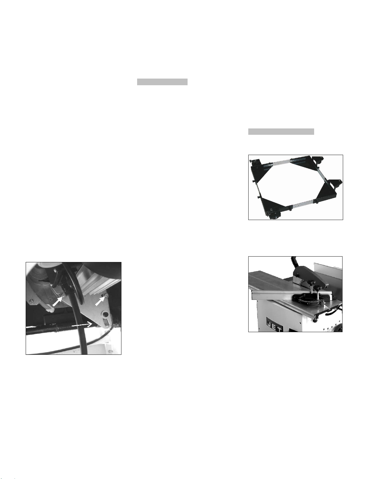
Remove rust from the table e.g. with
WD-40 and a Scotch-Brite™ Hand
Pad.
Never smoke while cleaning the
machine, and especially when using
petrol, kerosene or other inflammable
products.
This could lead to an explosion and
serious burns for the operator.
Saw blades:
Check saw blades regularly for faults.
Replace a defective sawblades
immediately.
Only use sharp and properly set saw
blades.
The servicing of saw blades should
only be performed by a trained person.
Main drive belt tensioning:
The machine is equipped with a
durable Poly-V belt
In case of belt slip (yelling noise), the
belt must be tightened.
Disconnect the machine form the
power source, pull mains plug.
Remove the front cabinet cover (CC,
Fig 25).
Tilt the sawblade to 45° for better
access.
Loosen the 2 hex bolts (Fig 27).
Fig 27
Tension the belt by lowering the
sawblade (spindle nut moves the
motor pivot plate).
Make sure the belt is not over
tensioned, because this could lead to
damage of the saw arbor and
bearings.
Tighten the bolts.
Reinstall front cabinet cover.
Motor Break:
The motor break works electromechanically (break motor).
If breaking time should exceed 10
seconds, the motor break assembly
needs to be replaced. Contact your Jet
service station immediately.
9. Trouble shooting
Motor doesn’t start
*No electricitycheck mains and fuse.
*Defective switch, motor or cordconsult an electrician.
*Overload has reactedWait and start again.
Machine vibrates excessively
*Stand on uneven floor-
adjust levelling screws for even
support.
*dust on saw flangesclean saw arbor and flanges.
*defective sawblade replace sawblade immediately
*Bad Poly-V-beltreplace Poly-V-belt
Cut is not accurately square
*Stops not adjusted correctlycheck with square and adjust stops.
Material binds blade when
ripping
*Fence not aligned with sawbladecheck and adjust rip fence.
*Wrapped woodselect another piece of wood.
Material kicked back from blade
*Fence not aligned with sawbladecheck and adjust rip fence.
*Raving knife not in placehigh danger, mount immediately with
guard.
Cutting surfaces is bad
*Wrong sawblade used
*Blade mounted backwards
*resin collection on sawblade
*sawblade is dull
*workpiece inhomogeneous
*Feed pressure too highDo not force the workpiece.
Blade does not raise or tilt
*Sawdust in mechanismsclean and regrease.
Sliding table does not move
*Sawdust in bearing guideswipe out any sawdust.
Low cutting performance
*Poly-V belt slips Tension main drive belt.
*Wrong voltage Check electric power supply
10. Environmental protection
Protect the environment.
Your appliance contains valuable
materials which can be recovered or
recycled. Please leave it at a
specialized institution.
11. Available accessories
Stock number 708118
Universal mobile base 250kg
Fig 25
Stock number 10000073
Precision mitre gauge with adjustable
stops -45° / 90° / +45°
Fig 26
Refer to the JET-Pricelist
for various accessories.
12. Safe operation
See appendix A (on the last pages of
this operating manual)
A.1.: Ripping
A.2.: Ripping of narrow stock
A.3.: Crosscutting on ripfence
A.4.: Use of push wood handle
11
Page 46
JTS-600XL
TABLE SAW
JTS-600XL…10000070XLM….230/50/1
JTS-600XL….10000070XLT….400/50/3
PARTS LIST
ERSATZTEILLISTE
LISTE DE PIECES
JPW (Tool) AG
Tämperlistrasse 5
CH-8117 Fällanden
Switzerland
Phone +41 44 806 47 48
Fax +41 44 806 47 58
www.jettools.com
P-10000070XM/XT 2015-08
Page 47
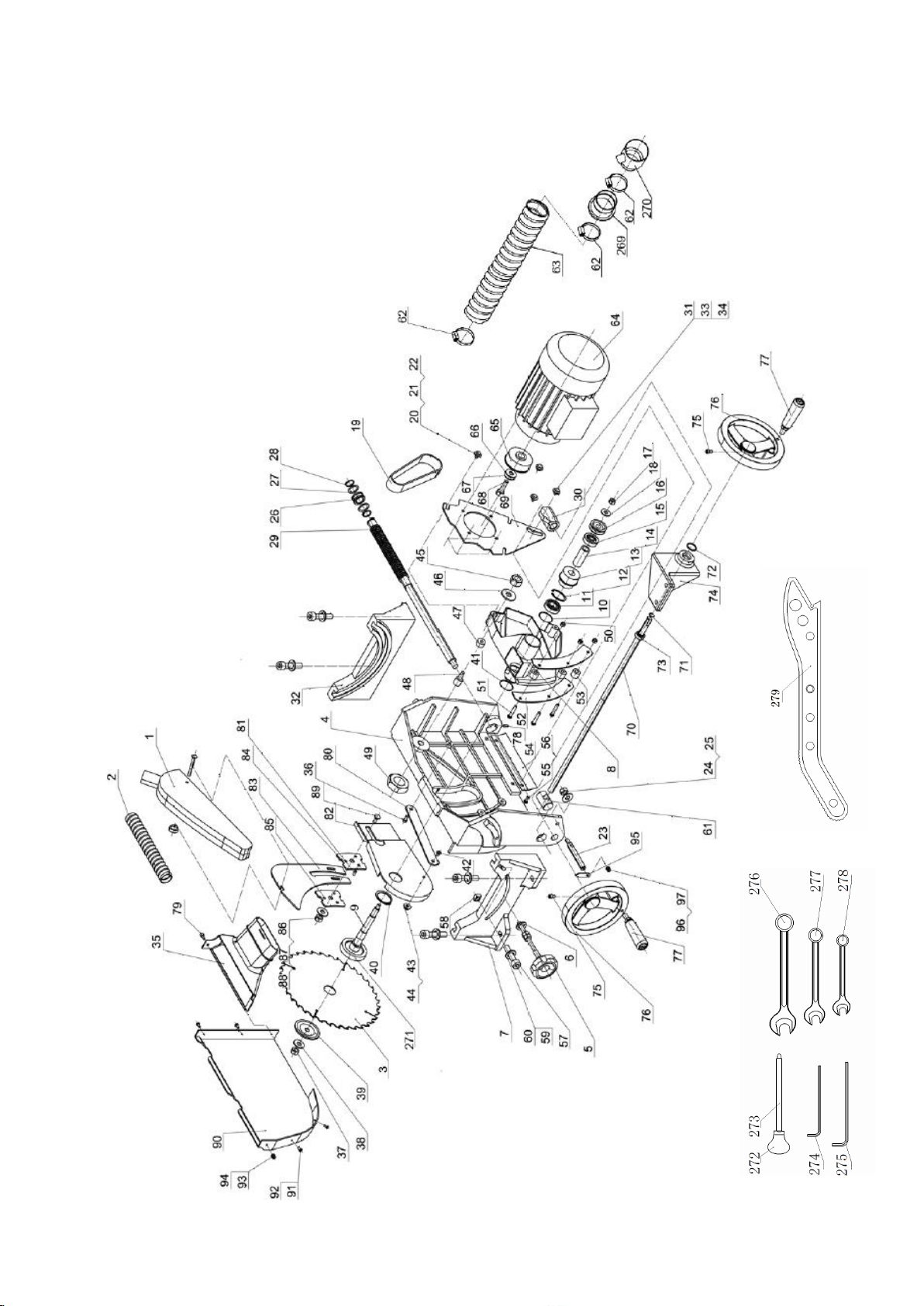
Trunnion Assembly for JTS-600XL
Page 48

Trunnion Assembly for JTS-600XL
Index
Part No.
Description
Size
Qty.
1
JTS600-001
Blade guard assy
1
2
JTS600-002
Dust collection tube(small)
1 3
JTS600-003
Blade
Ø250x3xØ30-36T
1 4 JTS600-004
Mount adjusting base
1 5
JTS600-005
Locking handle assy
1 6
JTS600-006
Washer
M8
1
7
JTS600-007
Rotating support base A
1
8
JTS600-008
Mount base
1 9
JTS600-009
Main shaft
1 10
JTS600-010
Adjusting washer
4 11
JTS600-011
Bearing
6003-RZ
1
12
JTS600-012
Retaining ring
1
13
JTS600-013
Shaft pulley
1 14
JTS600-014
Tube
1 15
JTS600-015
Bearing
6301-RZ
1
16
JTS600-016
Adjusting wheel
1 17
JTS600-017
Nut
M8
1
18
JTS600-018
Washer
M8
1
19
JTS600-019
Poly-belt
1 20
JTS600-020
Hex screw
M6X30
3
21
JTS600-021
Washer
M6 3 22
JTS600-022
Washer
M6 3 23
JTS600-023
Indicator rod
1
24
JTS600-024
Nut
M8
1
25
JTS600-025
Washer
M8 1 26
JTS600-026
Tube
1 27
JTS600-027
Washer
2 28
JTS600-028
Retaining ring
2
29
JTS600-029
Thread rod
1
30
JTS600-030
Thread tube
1 31
JTS600-031
Tube
1 32
JTS600-032
Rotating support base B
1 33
JTS600-033
Position screw
1 34
JTS600-034
Washer
M8
1
35
JTS600-035
Dust funnel
1
JTS600-035A
Funnel & hose clamp assly.(35,
62)
1
36
JTS600-036
Screw
1 37
JTS600-037
Right hand nut
M10X1.5
1
38
JTS600-038
Washer
M10
1
39
JTS600-039
Blade flange
1
40
JTS600-040
Retaining ring
1 41
JTS600-041
Washer
2 42
JTS600-042
Screw
M6X20
1
43
JTS600-043
Nut
M6 1 44
JTS600-044
Washer
M6
2
45
JTS600-045
Nut
M8
1
46
JTS600-046
Washer
M8 1 47
JTS600-047
Tube II
1 48
JTS600-048
Position screw
1 49
JTS600-049
Nut
M6
1
50
JTS600-050
Nut
M6
3
51
JTS600-051
Screw
M6X35
3
52
JTS600-052
Clamping plate
2
53
JTS600-053
Tube I
3 54
JTS600-054
Guard for thread rod
1 55
JTS600-055
Washer
M6
2
Page 49

Trunnion Assembly for JTS-600XL
Index
Part No.
Description
Size
Qty.
56
JTS600-056
Pan head screw
M6X8
2
57
JTS600-057
Nut
M8X20
2
58
JTS600-058
Square Nut
2 59
JTS600-059
Washer
M8
2
60
JTS600-060
Internal washer
M8
2
61
JTS600-061
45degree tilting rod
1 62
JTS600-062
Hose clamp
3 63
JTS600-063
Dust collection hose(big)
1 64
JTS600-064E
Motor 230V/50Hz/1
1
JTS600-064AE
Motor 400V/50Hz/3
1
JTS600-064RCE
Running Capacitor (not shown)
(20uF/ 450VAC)
1
JTS600-064-B
Motor Break replacement parts
assembly (not shown)
1
65
JTS600-065
Motor pulley
1
66
JTS600-066
Anti back washer
1
67
JTS600-067
Washer
M8
1
68
JTS600-068
Screw
1 69
JTS600-069
Motor mounting bracket
1 70
JTS600-070
Tilting thread rod
1 71
JTS600-071
Clamping ring
M12
1
72
JTS600-072
Clamping ring
M22
1
73
JTS600-073
Joint bearing
1
74
JTS600-074
Bracket for joint bearing
1 75
JTS600-075
Screw
M6X16
2
76
JTS600-076
Big handle wheel
2 77
JTS600-077
Handle
2
78
JTS600-078
Scew
M6X10
1
79
JTS600-079
Knob
1 80
JTS600-080
Connecting plate
1 81
JTS600-081
Hex socket screw
M6x10
3
82
JTS600-082
Bracket for riving knife
1 83
JTS600-083
Riving knife
1
84
JTS600-084
Guide plate
1
85
JTS600-085
Press plate
1 86
JTS600-086
Washer
M10
1
87
JTS600-087
Nut
M10
1
88
JTS600-088
Spring washer
M10
1
89
JTS600-089
Screw
M10X25
1
90
JTS600-090
Inside blade guard
1
91
JTS600-091
Screw
M4X10
3
92
JTS600-092
Washer
M5 5 93
JTS600-093
Screw
M4X20
2
94
JTS600-094
Self lock nut
M4 2 95
JTS600-095
Angle indicator
1
96
JTS600-096
Washer
M4
1
97
JTS600-097
Screw
M4X8
1
269
JTS600-269
Cabinet adapter
1 270
JTS600-270
Hose adapter (Y-piece)
1 271
JTS600-271
Blade flange
1
272
JTS600-272
Ball handle
1
273
JTS600-273
Handlebar
1 274
JTS600-274
Allen key
6mm
1
275
JTS600-275
Allen key
5mm
1
276
JTS600-276
Socket wrench
16mm
1
277
JTS600-277
Socket wrench
13mm
1
278
JTS600-278
Socket wrench
10mm
1
279
JTS600-279
Pushing handle
1
Page 50
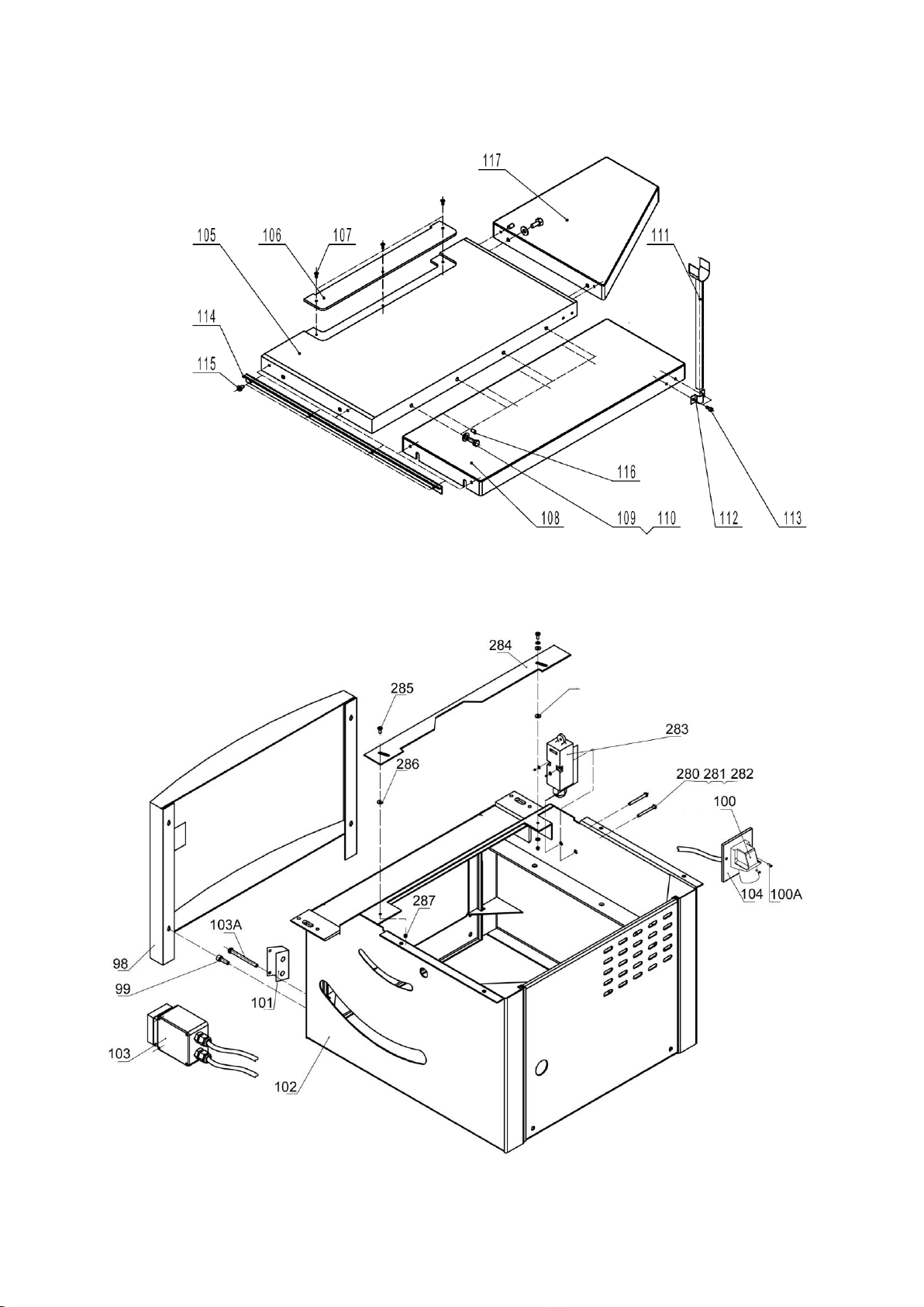
Table and Frame Assembly for JTS-600XL
Page 51

Table and Frame Assembly for JTS-600XL
Index
Part No.
Description
Size
Qty.
98
JTS600-098
Upper acr panel
1 99
JTS600-099
Screw
M6X16
2
100
JTS600-100E
Plug 230V/50Hz/1
1
JTS600-100AE
Plug 400V/50Hz/3
1
100A
JTS600-100A
Screw
M4X15
4
101
JTS600-101
Switch mounting plate
1 102
JTS600XL-102
Upper frame assembly
1 103
JTS600XL-103E
Switch Assembly 230V/50Hz/1
1
JTS600XL-103AE
Switch Assembly 400V/50Hz/3
1
103A
JTS600-103A
Screw
M4X60
2
104
JTS600-104
Plug mounting plate
1 105
JTS600X-105
Main table
1 106
JTS600-106
Table insert
1
107
JTS600-107
Screw
M5x8
3
108
JTS600X-108
Right Extension Table
1
109
JTS600-109
Hex bolt
M8X12
6
110
JTS600-110
Washer
M8 6 111
JTS600-111
Support bracket
1 112
JTS600-112
Semicircular bracket
1 113
JTS600-113
Hex socket screw
M6X16
2
114
JTS600-114
Front rail
1
115
JTS600-115
Pan head screw
M6X16
4
116
JTS600X-116
Hex socket set screw
M6X12
6
117
JTS600X-117
Rear extension table
1 280
JTS600XL-280
Pan head screw
M4X30
2
281
JTS600XL-281
Washer
M4
2
282
JTS600XL-282
Nut 2
283
JTS600XL-283
Micro switch
1 284
JTS600XL-284
Guard
1 285
JTS600XL-285
Screw
M5X8
3
286
JTS600XL-286
Split damping ring
3 287
JTS600XL-287
Nylon nut
2
Page 52
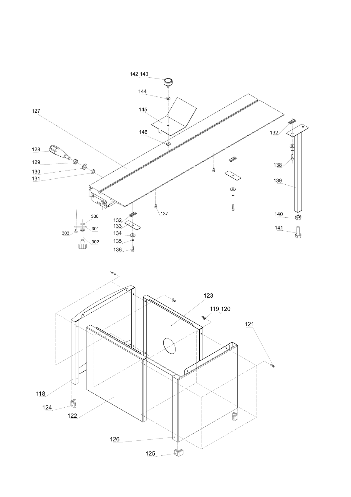
Sliding Table and Cabinet Assembly for JTS-600XL
Page 53

Index
Part No.
Description
Size
Qty.
118
JTS600-118
Lower arc panel
1 119
JTS600-119
Nut
M6 8 120
JTS600-120
Washer
M6 8 121
JTS600-121
Hex screw
M6X15
8
122
JTS600-122
Base front panel
1
123
JTS600-123
Base rear panel
1 124
JTS600-124
Foot for arc panel
2 125
JTS600-125
Foot for side panel
2 126
JTS600-126
Base side panel
1
127
JTS600XL-127
Sliding table ASSY
1
128
JTS600XL-128
Star locking handle
1 129
JTS600XL-129
Hex nut
M10
1
130
JTS600XL-130
Washer
1 131
JTS600XL-131
Square nut
1 132
JTS600XL-132
Sliding block
6
133
JTS600XL-133
Shim plate
2
134
JTS600XL-134
Washer
6 135
JTS600XL-135
Spring washer
6 136
JTS600XL-136
Hex socket screw
M8X25
2
137
JTS600XL-137
Hex socket screw
M6X10
2
138
JTS600XL-138
Hex socket screw
M8X16
4
139
JTS600XL-139
Support pin
2
140
JTS600XL-140
Hex nut
M16
2
141
JTS600XL-141
Hexagonal head bolt
M16X55
2
142
JTS600XL-142
Damper Knob ASSY
1 143
JTS600XL-143
Hex Bolt
M6X20
1
144
JTS600XL-144
Washer
1
145
JTS600XL-145
Push plate
1 146
JTS600XL-146
Square nut
1 300
JTS600XL-300
Hex nut
2 301
JTS600XL-301
Fixing plate
1 302
JTS600XL-302
Locating pin
1
303
JTS600XL-303
Screw
2
304
JTS600XL-304
Locating Assembly (#300 thru 303)
1
Sliding Table and Cabinet Assembly for JTS-600XL
Page 54
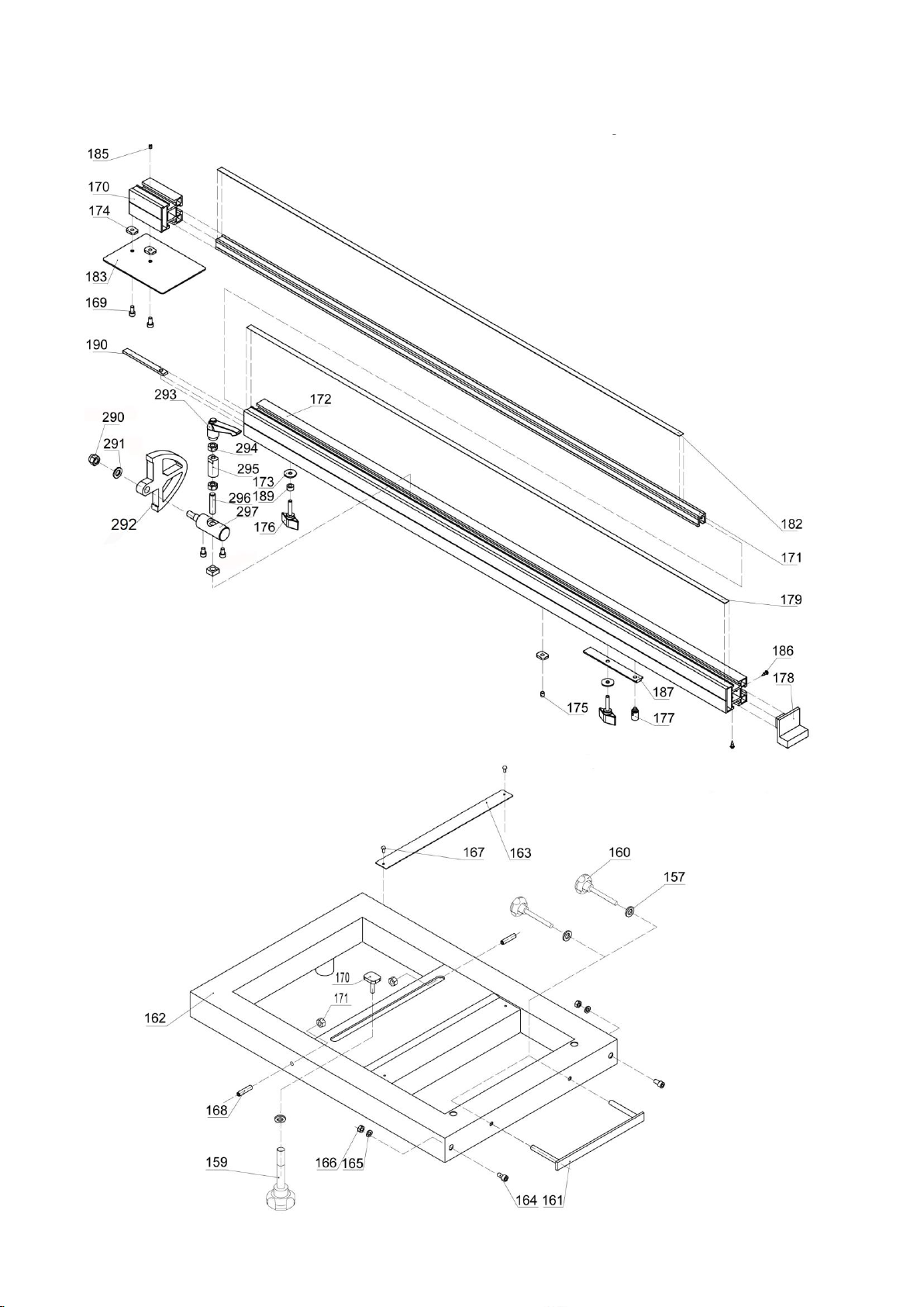
Outriger Table and Pull-out Miter Gauge Assembly for JTS-600XL
Page 55

Index
Part No.
Description
Size
Qty.
157
JTS600-157
Washer
M6 7 158
JTS600-158
Locking block
1 159
JTS600-159
Locking handle
1 160
JTS600-160
Locking handle
2
161
JTS600-161
Clamping plate
1
162
JTS600-162
Ext. sliding frame
1 163
JTS600-163
Angle ruler
1 164
JTS600-164
Location screw
2 165
JTS600-165
Washer
M8
2
166
JTS600-166
Hex nut
M8
4
167
JTS600-167
Revit
2 168
JTS600-168
Hex socket nut
M8X40
2
169
JTS600-169
Hex socket screw
M6X12
2
170
JTS600-170
Ext. bracket for lengthened
1
171
JTS600-171
Main bracket for lengthened ruler
1
172
JTS600-172
Fence
1
173
JTS600-173
Washer
M6 2 174
JTS600-174
Square nut
4 175
JTS600-175
Hex socket screw
M6X10
1
176
JTS600-176
Knob
3 177
JTS600-177
Pivot
1
178
JTS600-178
Fence cover
1
179
JTS600-179
Ruler I
1 182
JTS600-182
Ruller III
1 183
JTS600-183
Location plate
1 184
JTS600-184
Ruler II
1
185
JTS600-185
Hex socket screw
M5X6
1
186
JTS600-186
Pan head screw
ST4X6
1
187
JTS600-187
Long plate
1 189
JTS600-189
Tube
1 190
JTS600-190
Fixing plate
1 290
JTS600XL-290
Hex Series Nuts
M10
1
291
JTS600XL-291
Washer
1
292
JTS600XL-292
Baffle plate
1 293
JTS600XL-293
Adjust handle
1 294
JTS600XL-294
Nut
M8 2 295
JTS600XL-295
Support for telescopic tube
1 296
JTS600XL-296
Hex socket screw
M8X50
1
297
JTS600XL-297
Pivot
1
Outriger Table and Pull-out Miter Gauge Assembly for JTS-600XL
Page 56
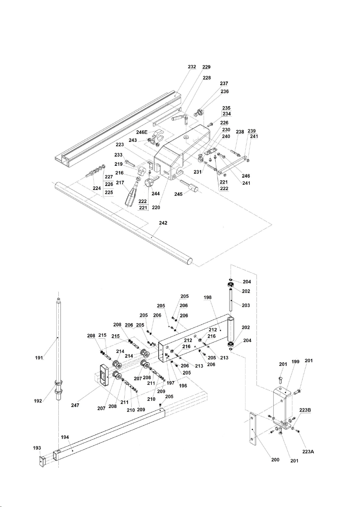
Rip Fence and Swing Arm Assembly for JTS-600XL
Page 57

Rip Fence and Swing Arm Assembly for JTS-600XL
Index
Part No.
Description
Size
Qty.
191
JTS600-191
Support rod
1 192
JTS600-192
Nut
M20
2
193
JTS600-193
Tube cap
2 194
JTS600XL-194
Telescopic tube
1 195
JTS600-195
End cover
1
196
JTS600-196
Screw
M4X8
2
197
JTS600-197
Washer
M5 2 198
JTS600-198
Support for telescopic tube
1 199
JTS600XL-199
Fixing bracket
1 200
JTS600-200
Connection plate
1
201
JTS600-201
Hex socket screw
M10X25
4
202
JTS600-202
Bearing
6202-RZ
2
203
JTS600-203
Shaft
1 204
JTS600-204
Clip ring
M15
2
205
JTS600-205
Screw
M6X10
7
206
JTS600-206
Washer
M6
6
207
JTS600-207
Lower wheel
2
208
JTS600-208
Bearing
61801-RZ
8
209
JTS600-209
Clip ring
M12
4
210
JTS600-210
Shaft
2 211
JTS600-211
Tube
2 212
JTS600-212
Outside baffle
2
213
JTS600-213
Nut
M6
2
214
JTS600-214
Upper wheel
2 215
JTS600-215
Eccentric shaft
2 216
JTS600-216
Hex socket screw
M6X25
2
217
JTS600-217
Locking handle
1
218
JTS600-218
Nut
M10
1
219
JTS600-219
Cam
1
219A
JTS600-219A
Cam & handle
assembly(#217,Thu 219)
1
223A
JTS600XL-233A
Hex socket screw
M8X25
4
223B
JTS600XL-233B
Nut
M8
4
Page 58

Rip Fence and Swing Arm Assembly for JTS-600XL
Index
Part No.
Description
Size
Qty.
220
JTS600-220
Rip fence bracket
1 221
JTS600-221
Screw
M5X8
3
222
JTS600-222
Washer
M5X8
3
223
JTS600-223
Clip spring
1 224
JTS600-224
Stud
4
225
JTS600-225
Nut
M8
4
226
JTS600-226
Washer
M8 9 227
JTS600-227
Nut
M8 4 228
JTS600-228
Handle
1 229
JTS600-229
Locking plate I
1
230
JTS600-230
Locking cam wheel
1
231
JTS600-231
Hex socket srcew
M8X18
1
232
JTS600-232
L-shape rip fence
1 233
JTS600-233
Hex socket srcew
M8X40
1
234
JTS600-234
Hex screw
M6X20
1
235
JTS600-235
Washer
M6
1
236
JTS600-236
Bearing
6000-RZ
1
237
JTS600-237
Bearing bracket
1 238
JTS600-238
Locking screw
2 239
JTS600-239
Locking plate II
1 240
JTS600-240
Support plate
1 241
JTS600-241
Hex nut
M6
5
242
JTS600-242
Fence bracket rail
1
243
JTS600-243
Self locking nut
M8 2 244
JTS600-244
Star locking handle
1 245
JTS600-245
Micro adjust handle
1 246
JTS600-246
Hex screw
M6X16
1
246E
JTS600-246E
Clamping bracket
1
247
JTS600-247
Insert, Swing Arm
1
Page 59
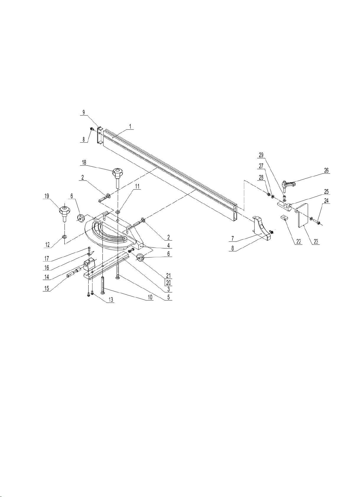
Miter Gauge Assembly for JTS-600XL------Optional Accessory
Stock Number: 10000073
Page 60
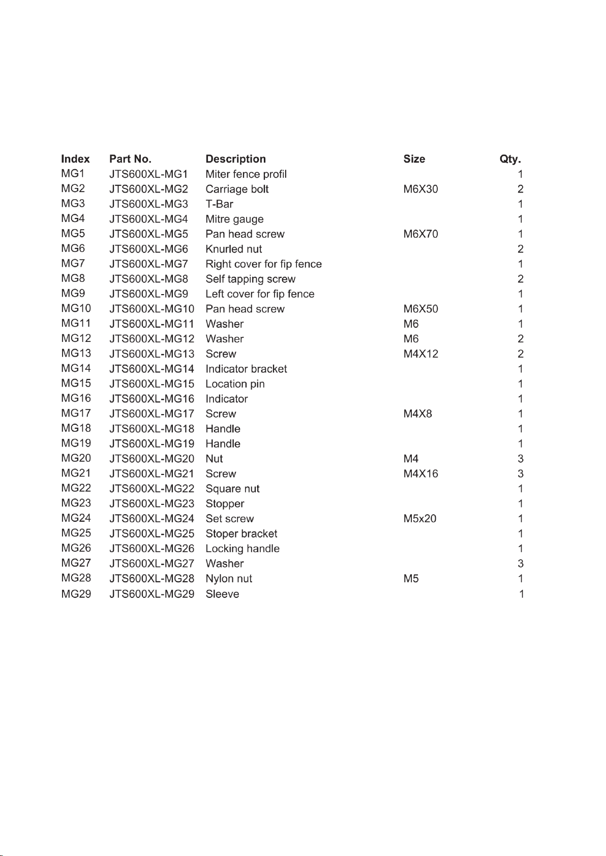
Miter Gauge Assembly for JTS-600XL------Optional Accessory
Stock Number : 10000073
Page 61
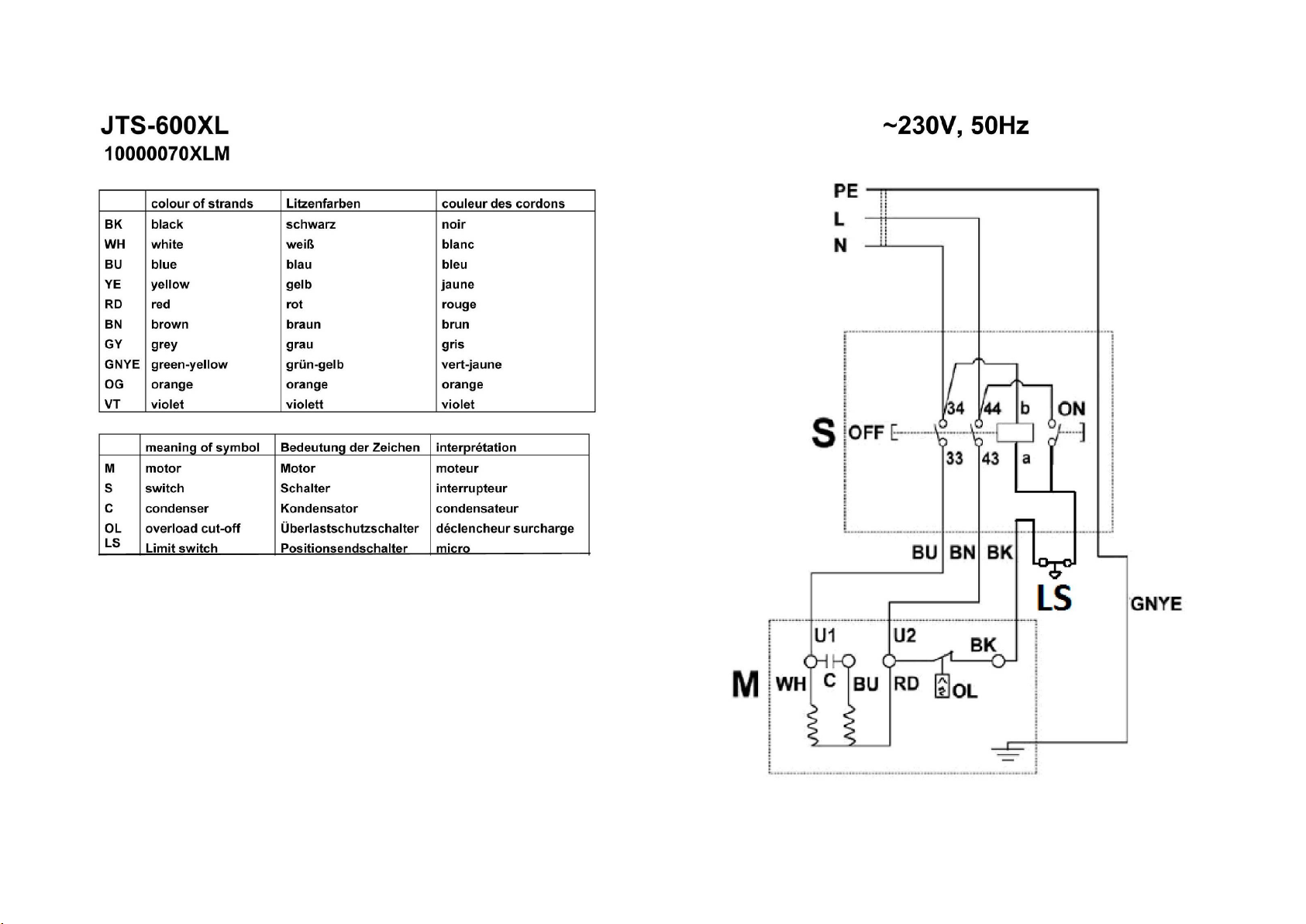
Page 62
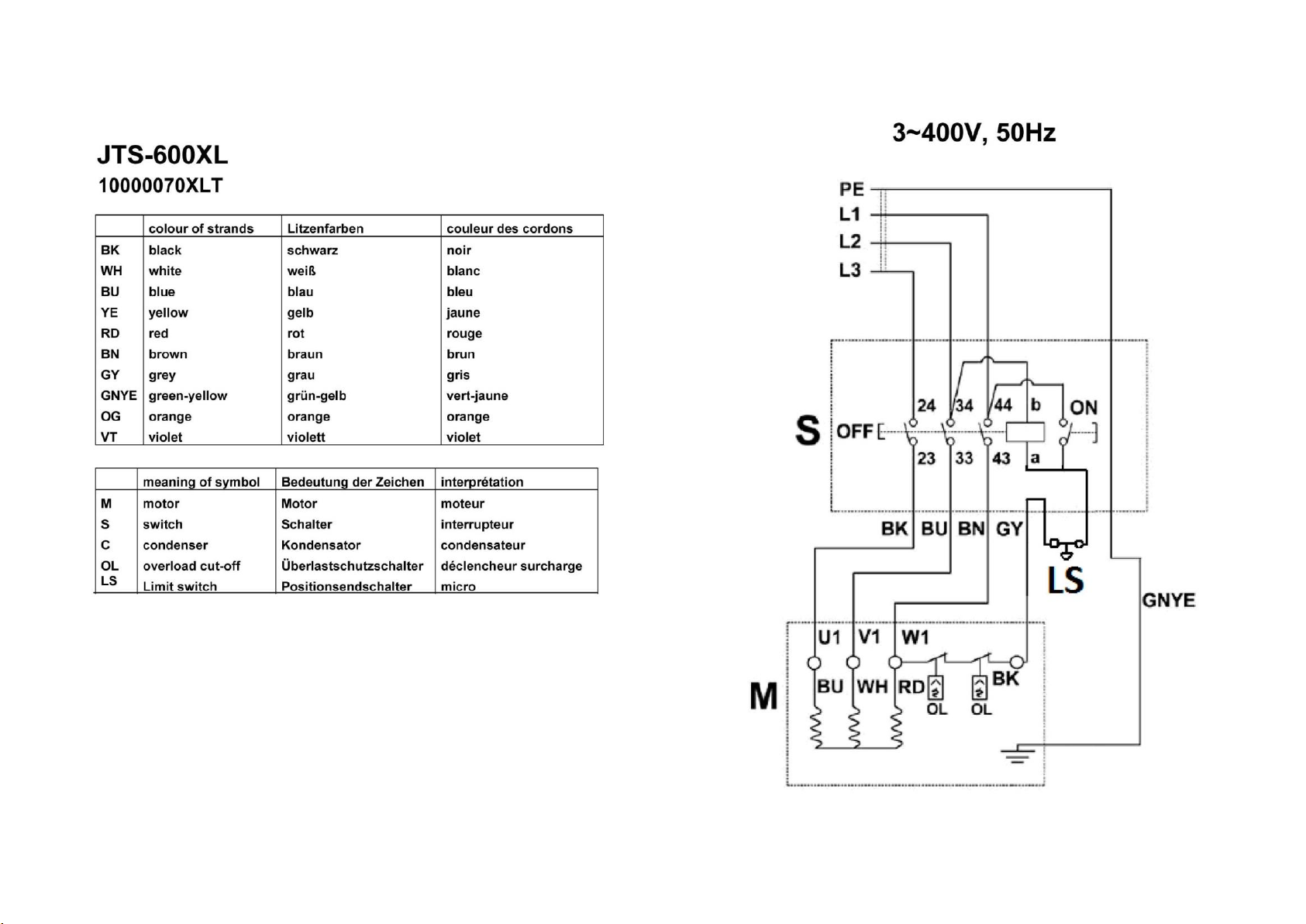
Page 63
13. Test reports with risk analysis
Hazards
Measures
1
Mechanical hazards (caused for example by:
- shape
- relative location
- mass and stability (potential energy of elements),
- mass and velocity (kinetic energy of elements)
- inadequacy of the mechanical strength
- accumulation of potential energy by: elastic
elements (springs),or liquids or gases under
pressure, or vacuum of the machine parts of
workpieces)
See below
1.1
Crushing hazard
Inherently safe machinery design
and construction and take
necessary protection measures:
1. The weight of machine is more than
110kg, they are stable enough.
2. Request adjustable sawblade
guard is provided to guard that portion
of the sawblade above the table
3.Slot for the sawblade in the table
meets the requirement.
4.The sawblade below the table was
protected by fixed guards.
5. The hazardous moving parts
cannot be accessed through the
openings for the chip removal.
6.All drive mechanisms are guarded
by a fixed guard.
Equipment: Table Saw
Type: TS250RC, TS250RS, TS250RC-B, TS250RS-B, TS250, TS250B
(Ser. No.: 20090500001, 20090500002, 20090500003, 20090500004,
20090500005, 20090500006)
Client: Qingdao Capital Resource Electric Co., Ltd.
Risk Analyses
Page 64

1.2
Shearing hazard
Inherently safe machinery design
and construction and take
necessary protection measures:
1. Request adjustable sawblade
guard is provided to guard that portion
of the sawblade above the table
2.Slot for the sawblade in the table
meets the requirement.
3. The sawblade below the table was
protected by fixed guards and
interlocked guard.
4. The hazardous moving parts
cannot be accessed through the
openings for the chip removal.
5. All drive mechanisms are guarded
by a fixed guard.
1.3
Cutting or severing hazard
Inherently safe machinery design
and construction and take
necessary protection measures:
1.The PC guard have 3mm thickness
and the guard below the table made
of steel with 2mm thickness (ultimate
tensile:350N/mm2)
2. Request adjustable sawblade
guard is provided to guard that portion
of the sawblade above the table
3.Slot for the sawblade in the table
meets the requirement.
4. The sawblade below the table was
protected by fixed guards.
5. The hazardous moving parts
cannot be accessed through the
openings for the chip removal.
6. Required flanges are provided.
1.4
Entanglement hazard
Inherently safe machinery design
and construction and take
necessary protection measures:
1. Required fence is provided.
2. Request adjustable sawblade
guard is provided to guard that portion
of the sawblade above the table
3.Slot for the sawblade in the table
meets the requirement.
4. The sawblade below the table was
protected by fixed guards.
5. The hazardous moving parts
cannot be accessed through the
openings for the chip removal.
6. Required flanges are provided.
Page 65
1.5
Drawing –in or trapping hazard
Inherently safe machinery design
and construction and take
necessary protection measures:
1. Request adjustable sawblade
guard is provided to guard that portion
of the sawblade above the table
2.Slot for the sawblade in the table
meets the requirement.
3. The sawblade below the table was
protected by fixed guards.
4. The hazardous moving parts
cannot be accessed through the
openings for the chip removal.
1.6
Impact hazard
Inherently safe machinery design
and construction and take
necessary protection measures:
1. Request adjustable sawblade
guard is provided to guard that portion
of the sawblade above the table
2.Slot for the sawblade in the table
meets the requirement.
3. The sawblade below the table was
protected by fixed guards.
4. The hazardous moving parts
cannot be accessed through the
openings for the chip removal.
1.7
Stabbing or puncture hazard
Not relevant
1.8
Friction or abrasion hazard
Not relevant
1.9
High pressure fluid injection hazard
Not relevant
1.10
Ejection of parts (of machinery and processed
materials/ workpieces)
Inherently safe machinery design
and construction, take necessary
protection measures and inform
users of the residual risks:
1.The PC guard have 3mm thickness
and the guard below the table made
of steel with 2mm thickness (ultimate
tensile:350N/mm2)
2. Required flanges are provided.
3. Required riving Knives (steel and
ultimate tensile: 580N mm2) and
indicated in the manual
4. Required fence is provided.
1.11
Loss of stability (of machinery and machine parts)
Inherently safe machinery design
and construction:
The weight of machine is more than
110kg, they are stable enough.
1.12
Slip, trip and fall hazards in relationship with machinery
(because of their mechanical nature)
Not relevant
2
Electrical hazards, caused for example by:
2.1
Electrical contact (direct or indirect)
Inherently safe machinery design
and construction:
Refer to Refer to EN 60204-1:1997
and EN1870-1:1999
2.2
Electrostatic phenomena
Not relevant
Page 66
2.3
Thermal radiation or other phenomena such as
ejection of molten particles, and chemical effects from
short-circuits, overloads; etc.
Not relevant
2.4
External influences on electrical equipment
Inherently safe machinery design
and construction:
Refer to Refer to EN 60204-1:1997
and EN1870-1:1999
3
Thermal hazards resulting in :
3.1
Burns an scalds, by a possible contact of persons, by
flames or explosions and also by the radiation of heat
sources
Not relevant
3.2
Health-damaging effects by hot or cold work
environment
Not relevant
4
Hazards generated by noise, resulting in :
4.1
Hearing losses (deafness).other physiological
disorders (e.g. loss of balance, loss of awareness)
Inform users of the residual risks:
The warning label “The operator must
wear ear protection device during the
operation” is found on the machinery
and manual
4.2
Interferences with speech communication, acoustic
signals, etc.
Not relevant
5
Hazards generated by vibration, (resulting in a variety
of neurological and vascular disorders)
Not relevant
6
Hazards generated by radiation, especially by :
Not relevant
6.1
Electrical arcs
Not relevant
6.2
lasers
Not relevant
6.3
ionizing radiation sources
Not relevant
6.4
Machines marking use of high frequency
electromagnetic fields
89/336/EEC addressed
7
Hazards generated by materials and substances
processed, used or exhausted by machinery for
example:
7.1
Hazards resulting form contact with or inhalation of
harmful fluids, gases, mists, fumes and dusts
Inherently safe machinery design
and construction:
An extraction outlet on the guard and
other below the table can ensure that
the chips and dust extracted from the
point of origin are conveyed to the
collection system
7.2
Fire or explosion hazard
Inherently safe machinery design
and construction:
Overload protection device is
provided.
7.3
Biological and microbiological (viral or bacterial)
hazards
Not relevant
8
Hazards generated by neglecting ergonomic principles
in machine design, mismatch of machinery with human
characteristics and abilities caused for example by:
Page 67
8.1
Unhealthy postures or excessive efforts
Inherently safe machinery design
and construction:
The position of switch is 650mm
above the floor.
8.2
Inadequate consideration of human hand-arm or footleg anatomy
No significant.
8.3
Neglected use of personal protection equipment
Inform users of the residual risks:
Relevant contents are raising up in
manual
8.4
Inadequate area lighting
Not significant
8.5
Mental overload or underload, stress, etc.
Not relevant
8.6
Human error
Not relevant
9
Hazard combinations
Not relevant
10
Hazards caused by failure of energy supply, breaking
down of machinery parts and other functional
disorders, for example:
10.1
Failure of energy supply (of energy and /or control
circuits)
Inherently safe machinery design
and construction:
Electromagnetic switch is used
10.2
Unexpected ejection of machine parts or fluids
Inherently safe machinery design
and construction, take necessary
protection measures:
See 1.10.
10.3
Failure, malfunction of control system (unexpected
start up, unexpected overrun)
Inherently safe machinery design
and construction:
Applying a cylindrical rod with a
hemispherical end with a diameter of
100mm to the switch and it was
impossible to start the appliance.
10.4
Errors of fitting
Inform users of the residual risks:
All relevant items are mentioned in
manual
10.5
Overturn, unexpected loss of machine stability
Inherently safe machinery design
and construction:
The weight of machine is more than
110kg, it is stable enough.
11
Hazards caused by (temporary) missing and/or
incorrectly positioned safety related measures/means,
for example:
11.1
All kinds of guard
Inherently safe machinery design
and construction and take
necessary protection measures:
1. Request adjustable sawblade
guard is provided to guard that portion
of the sawblade above the table
2.Slot for the sawblade in the table
meets the requirement.
3. The sawblade below the table was
protected by fixed guards.
4. The hazardous moving parts
cannot be accessed through the
openings for the chip removal.
11.2
All kinds of safety related (protection) devices
No relevant.
Page 68
11.3
Starting and stopping devices
Inherently safe machinery design
and construction:
Meet the requirements
11.4
Safety signs and signals
Inform users of the residual risks:
All relevant items are mentioned in
manual
11.5
All kinds of information or warning devices
Inform users of the residual risks:
All relevant items are mentioned in
manual
11.6
Energy supply disconnecting devices
Inherently safe machinery design
and construction:
Plug provided with the machine.
11.7
Emergency devices
Inherently safe machinery design
and construction:
Main switch has EMO function.
11.8
Feeding /removal means of workpieces
Inherently safe machinery design
and construction:
Required fence is provided
11.9
Essential equipment and accessories for safe
adjusting and/or maintaining
The information for maintenance is
given in the manual
11.10
Equipment evacuating gases, etc.
Inherently safe machinery design
and construction:
An extraction outlet on the guard and
other below the table can ensure that
the chips and dust extracted from the
point of origin are conveyed to the
collection system
Manufacturer:
Qingdao Capital Resource Electric Co. LTD
Signature company stamp
Place/Date
Page 69
TÜV Rheinland / CCIC (Qingdao) Co., Ltd.
TÜV Rheinland / CCIC (Qingdao)
Co., Ltd.
莱茵技术-商检(青岛)有限公司
6F, No.2 Bldg., No. 175
Zhuzhou Road,
266101 Qingdao, P.R. China
青岛市株洲路 175号 2 号楼
6层
邮编:266101
Tel:(86) 532- 8870 6655
Fax: (86) 532- 8870 6669
e-mail: [email protected]
Internet: http://www.chn.tuv.com
Qingdao Capital Resource Electric Co., Ltd.
Date : 2014-07-23
155 Zhuzhou Road, Qingdao
Our ref. : WYH
Shandong 266101
P. R. China
Type of Equipment
Model Designation
Report No.
Member of TÜV Rheinland Group
Ref : Testing Report
: Table Saw
: Refer to test report
: 17702074 003
Dear Ms. Mu Shenghua,
Please find enclosed your authorized copy of the Test Report for the above mentioned
technical equipment.
We appreciate your support and would like to offer our assistance in the approval of
your future products through our extensive range of technical services. Please feel free
to contact us whatever your requirements may be.
With kind regards,
Dong Huajian
Manager
Enclosure
Page 70
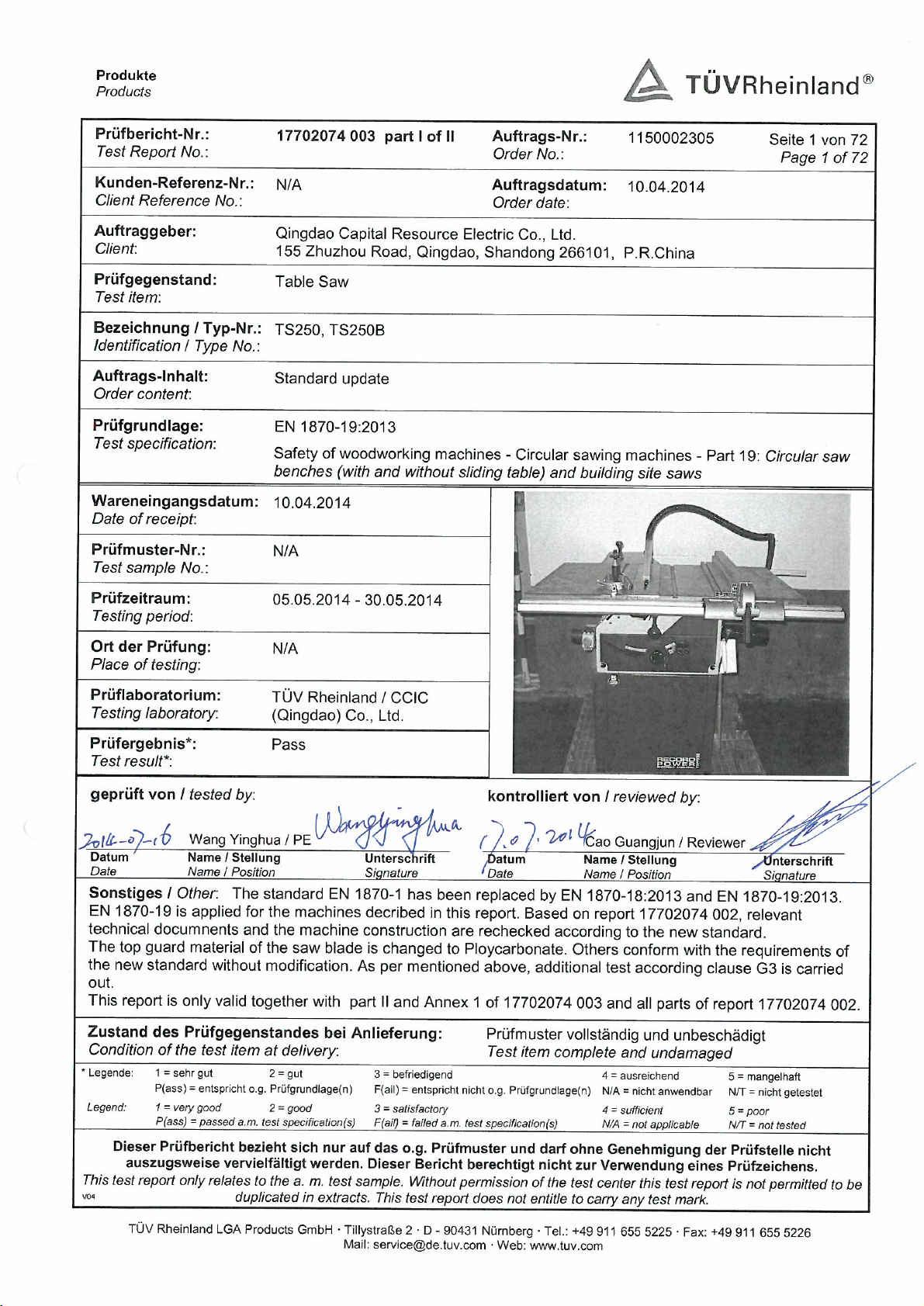
Page 71
Test Report No.: 17702074 003
Part I of II
Page 2 of 72
EN 1870-19:2013
Clause
Requirement
Remarks - Results
Verdict
4
List of significant hazards
--
This clause contains all significant hazards, hazardous
situations and events (see EN ISO 12100:2010), identified
by risk assessment as significant for the machines as
defined in the scope and which require action to eliminate
or reduce the risk. This document deals with these
significant hazards by defining safety requirements and/or
measures or by reference to relevant standards.
These hazards are listed in Tables 1 and 2.
Informative clause.
--
5
Safety requirements and/or measures
P
5.1
General
P
The machine shall comply with the safety requirements
and/or protective measures of Clause 5.
In addition, the machine should be designed according to
the principles of EN ISO 12100:2010 for hazards relevant
but not significant, which are not dealt with by this
document (e.g. sharp edges of the machine frame).
For guidance in connection with risk reduction by design,
see EN ISO 12100:2010, 6.2, and for safeguarding
measures, see EN ISO 12100:2010, 6.3.
Considered.
P
5.2
Controls
P
5.2.1
Safety and reliability of control systems
P
5.1.1.1
General
P
For the purpose of this document, safety related part of a
control system means the system from the initial device,
e.g. actuator or position detector or sensor up to and
including the power control element of the final machine
actuator, e.g. motor or brake. Safety related parts of the
control system of this machine comprise parts concerning
the following functions and they shall fulfil at least the
requirements of the PL given below in accordance with
the requirements of EN ISO 13849-1:2008:
a) starting and restarting: PL=c (see 5.2.3);
b) prevention of unexpected start up: PL=c (see 5.2.3,
5.2.9);
c) normal stopping: PL=c (see 5.2.4);
Start/stop control is
hardwired. Category 1 and
PL=c achieved.
P
Page 72
Test Report No.: 17702074 003
Part I of II
Page 3 of 72
EN 1870-19:2013
Clause
Requirement
Remarks - Results
Verdict
d) emergency stop: PL=c (see 5.2.5);
e) interlocking of guards: PL=c (see 5.2.8, 5.3.7.3);
f) interlocking of functions: PL=c (see 5.2.8, 5.2.3,
5.3.7.3);
g) detecting of the selected speed of the main saw blade:
PL=b or PL=c (see 5.2.6);
h) speed control of the main saw blade drive if fitted :
PL=c (see 5.2.6);
i) hold-to-run control circuit: PL=c or P=b in conjunction
with an initiation control device in PL=c (see 5.2.7,
5.3.7.4);
j) power operated adjustment of the saw blade(s) or
fence(s): PL=b (see 5.2.7);
k) power operated adjustment movements initiation: PL=c
(see 5.2.7);
l) braking system: PL=b or PL=c (see 5.3.4.1);
m) powered workpiece clamping system: PL=c (see
5.3.7);
Verification: By checking the relevant drawings and/or
circuit diagrams and inspection of the machine.
5.2.1.2
Use of protective devices
No protective device used.
N/A
Protective devices shall be in accordance with the specific
standards. For the devices listed below, the following
requirements apply:
a) magnetic/proximity switches shall be in accordance
with the requirements of EN 1088:1995+A2:2008, 6.2
and the related control system shall be at least PL=c in
accordance with the requirements of EN ISO 138491:2008;
b) if a time delay is used it shall be at least PL=c in
accordance with the requirements of EN ISO 138491:2008
Also see 5.4.7 for the EMC requirements on the complete
machine.
Verification: By checking the relevant drawings and/or
circuit diagrams, inspection of the machine, measurement
and relevant functional testing of the machine.
NOTE For the components characteristics a confirmation
Page 73
Test Report No.: 17702074 003
Part I of II
Page 4 of 72
EN 1870-19:2013
Clause
Requirement
Remarks - Results
Verdict
from the components' manufacturers can be useful.
5.2.2
Position of controls
P
5.2.2.1
General P
All hand-operated controls shall be located ≥ 600 mm
above floor level.
The start control for the main saw blade and the scoring
saw blade (where fitted on circular saw benches) shall be
situated adjacent to one of the stop controls for the saw
blade(s).
An emergency stop control required by 5.2.5 shall be
situated adjacent to the start control for the saw blade(s).
Verification: By checking the relevant drawings,
measurement and inspection of the machine.
Start and stop button are
located 680mm above the
operating level.
P
5.2.2.2
Circular saw benches without sliding table and
building site saws
P
For circular saw benches designed to be used without a
sliding table and building site saws, the electrical control
devices for normal stopping and emergency stop (if
provided, see 5.2.5) shall be situated as follows (see the
shaded area marked X or the shaded area marked Y in
Figure 4):
a) at the operator's position; and
b) either below the table located in a fixed position at a
distance of at least 50 mm from the table top and more
than 600 mm above the floor (see a) in Figure 4) and:
1) on the left side of the machine (area X) and
extending not more than half of the table length L
(see b) in Figure 4); or
2) on the front side of the machine (area Y) on the left
of the cutting line; or
c) on a movable control panel fixed to the machine
located so that:
1) its front face is at a distance from the front edge of
the table not exceeding 700 mm;
2) its upper surface is at a distance from the floor level
not exceeding 1 800 mm.
Start / stop button are
150mm below the table
and 680mm above the
floor. Located on the front
side of the machine (area
Y).
P
Page 74
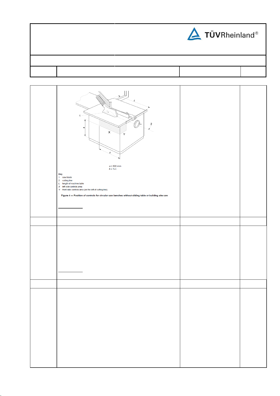
Test Report No.: 17702074 003
Part I of II
Page 5 of 72
EN 1870-19:2013
Clause
Requirement
Remarks - Results
Verdict
5.2.2.3
Circular saw benches with sliding table
N/A
For circular saw benches equipped with a sliding table
and/or where provision is made for the use of a sliding
table, the electrical control devices for normal stopping
and emergency stop (if provided, see 5.2.5) shall be
situated in the shaded area marked Y in Figure 4, or on a
movable control panel.
Verification: By checking the relevant drawings,
measurement and inspection of the machine.
5.2.3
Starting P
Before starting the saw blade(s) all interlocked guard(s)
(where fitted as indicated in 5.3.7) shall be in place and
functional. This is achieved by the interlocking
arrangements described in 5.3.7.
Start or restart shall only be possible by actuation of the
start control device provided for that purpose.
Closure of movable interlocked guards shall not lead to an
automatic restart of hazardous movements.
The safety related part of the control systems (also see
5.2.1) for starting and the interlocking arrangements as
indicated in 5.2.7, 5.2.8, 5.3.6, 5.3.7 shall be at least PL=c
No interlocking guards.
PL=c for start control.
Verification: By checking the relevant drawings,
measurement and inspection of the machine.
Page 75
Test Report No.: 17702074 003
Part I of II
Page 6 of 72
EN 1870-19:2013
Clause
Requirement
Remarks - Results
Verdict
in accordance with the requirements of EN ISO 138491:2008.
When fitted with a unit for scoring the scoring saw blade
spindle drive motor shall not be capable of being started
before the main saw blade drive motor.
For electrically operated machines the requirements of
EN 60204-1:2006, 9.2.5.2 but the exceptions described in
EN 60204-1:2006, 9.2.5.2 are not relevant.
The safety related part of the control systems (also see
5.2.1) for interlocking between starting of the main saw
blade drive motor and starting of the scoring saw blade
spindle drive motor shall be at least PL=c in accordance
with the requirements of EN ISO 13849-1:2008 (see also
5.2.6, 5.3.7).
Verification: By checking the relevant drawings and/or
circuit diagrams, inspection of the machine and relevant
functional testing of the machine.
5.2.4
Normal stopping
P
The machine shall be fitted with a stop control where by
all saw blades and – if fitted – a demountable power feed
unit can be stopped (see also 5.2.8). The stopping shall
include disconnection from energy supply of the
corresponding actuators unless STO in accordance with
EN 61800-5-2:2007 is used.
Machines where the emergency stop control device (see
5.2.5) is not required the normal stop control device shall
not be shrouded.
For normal stopping of PDS(SR) (power drive system,
safety related) see 4.2.2.2 "safe torque off (STO)” and
4.2.2.3 “safe stop 1 (SS1)” of EN 61800-5-2:2007.
If the machine is fitted with a spring operated mechanical
brake this stop control shall be of category 0 in
accordance with the requirements of EN 60204-1:2006,
9.2.2.
If the machine is fitted with any other type of brake, e.g.
electrical brake, this stop control shall be of category 1 in
accordance with the requirements of EN 60204-1:2006,
9.2.2.
Where a category 1 stop control is fitted, the stopping
sequence shall be:
Stop button directly
disconnect the coil supply
of the electromagnetic
power switch.
Category 0 stop and PL=c
achieved.
Page 76
Test Report No.: 17702074 003
Part I of II
Page 7 of 72
EN 1870-19:2013
Clause
Requirement
Remarks - Results
Verdict
a) cut power to saw blade(s) drives actuators and any
sockets (if provided) and actuate the brake(s);
b) cut power to brake(s) (if electrical brake is fitted) after
the saw blade(s) has come to rest, e.g. by using a time
delay in accordance with 5.2.1.2 b);
If a time delay device is used the time delay shall conform
to 5.2.1.2 b) and be at least the maximum run-down time.
Either the time delay shall be fixed or the time delay
adjustment device shall be sealed.
The safety related part of the control systems (also see
5.2.1) for normal stopping shall be at least PL=c in
accordance with the requirements of EN ISO 138491:2008.
Verification: By checking the relevant drawings and/or
circuit diagrams, inspection of the machine and relevant
functional testing of the machine.
5.2.5
Emergency stop
N/A
The requirements of EN ISO 13850:2008 apply and in
addition:
Circular saw benches with main saw blade and scoring
saw blade driven by separate motors and/or where
provision is made for use of a demountable power feed
unit (e.g. a plug) and/or fitted with power driven
adjustments of the saw unit and/or fences shall be fitted
with an emergency stop control which cut power to all
machine actuators except workpiece clamping and which
complies with the requirements of EN 60204-1:2006,
9.2.5.4.2 and 10.7. The emergency stop control device
shall be at any time of self latching type.
For emergency stop of PDS(SR) see 4.2.2.2 "safe torque
off (STO)” and 4.2.2.3 “safe stop 1 (SS1)” of EN 61800-52:2007.
If the machine is fitted with a spring actuated mechanical
brake this stop control shall be of category 0 in
accordance with the requirements of EN 60204-1:2006,
9.2.2.
If the machine is fitted with any other type of brake, e.g.
electrical brake, this stop control shall be of category 1 in
accordance with the requirements of EN 60204-1:2006,
9.2.2.
Where a category 1 stop control is fitted, the stopping
Only one sawblade motor.
A stop button adjacent with
the start button is provided
in the operating position
and easily accessed so
that the operator can stop
the machine a.s.a.p.
Emergency stop in not
necessary.
N/A
Page 77
Test Report No.: 17702074 003
Part I of II
Page 8 of 72
EN 1870-19:2013
Clause
Requirement
Remarks - Results
Verdict
sequence shall be:
a) cut power to all machine actuators and any sockets (if
provided) except workpiece clamping (if fitted) and
actuate the brake;
b) cut power to brake (if electrical brake is fitted) after the
saw spindle has come to rest, e.g. by using a time
delay in accordance with 5.2.1.2 b).
If a time delay device is used the time delay shall conform
to 5.2.1.2 b) and shall be at least the maximum run-down
time. Either the time delay shall be fixed or the time delay
adjustment device shall be sealed.
The safety related part of the control systems (also see
5.2.1) for the emergency stop shall be at least PL=c in
accordance with the requirements of EN ISO 138491:2008.
Verification: By checking relevant drawings and/or circuit
diagrams, inspection of the machine and relevant
functional testing of the machine.
5.2.6
Speed control for circular saw benches
N/A
Where a circular saw bench is designed to operate at
more than one main saw blade/milling tool speed, the
following conditions shall be met:
The selected speed shall be visible or indicated at the
operator's position.
On circular saw benches with varying the main saw blade
speed by changing the belts on the pulleys the control
system for indication of the main saw blade speed shall at
least conform to PL=b in accordance with the
requirements of EN ISO 13849-1:2008.
On circular saw bench fitted with an incremental speed
change motor, e.g. a change pole motor, the speed shall
at least be selected in PL=c in accordance with the
requirements of EN ISO 13849-1:2008 and be indicated in
rpm at the control.
On circular saw bench fitted with an automatic control
device for infinitely varying the speed (e.g. a frequency
inverter) for the main saw blade the device shall be such
that the actual speed shall not exceed the selected speed
by more than 10 %. The selected speed shall be indicated
prior to main saw blade start at the control. The safety
related part of the control system for speed control shall
be PL=c in accordance with the requirements of EN ISO
Fixed rotation speed.
N/A
Page 78
Test Report No.: 17702074 003
Part I of II
Page 9 of 72
EN 1870-19:2013
Clause
Requirement
Remarks - Results
Verdict
13849-1:2008. The actual speed of the main saw blade
shall be compared with the selected speed continuously.
If the actual speed exceeds the selected speed by more
than 10 % the main saw blade shall stop automatically.
This stop shall be a category 0 stop according EN 602041:2006, 9.2.2. In addition, the following measures against
loss or falsification of data shall be taken:
a) measures against loss of the data for main saw blade
or milling tool selected speed stored in the machine
control if stored data result in an automatic selection of
the intended main saw blade/milling tool speed:
1) safety related data for the machine tools shall be
stored either in 2 independent memory chips or
stored two times in one single chip (one time
inverse);
2) after input of the safety related data for the tools the
data shall be confirmed by the operator;
3) the two data shall be compared automatically at
each switching on of the isolator, at each fetch of the
data, at least once per shift. If the two data are not
identical it shall be impossible to start the spindle
motor or if running the spindle motor shall be
stopped and a warning signal shall be given;
4) for monitoring of failures the processor comparing
the data shall have a watch dog function;
b) measures against falsification in data transfer between
manual control, data stored in the machine control,
display for the data and control of the inverter:
1) selected spindle speed shall be stored in the control
of the inverter or in the unit which monitors the actual
speed;
2) selected speed transmitted to the control of the
inverter or to the unit which monitors the actual
speed shall be read back and monitored on the
display for checking by the operator.
Where a circular saw bench has the facility for grooving
with a milling tool, it shall be possible to operate at a
grooving tool cutting speed of at least 40 m s-1 with the
allowed tool diameters defined in the instruction manual.
Verification: By checking relevant drawings and/or circuit
diagrams, calculation, inspection of the machine and
relevant functional testing of the machine.
NOTE For the components characteristics a confirmation from
Page 79
Test Report No.: 17702074 003
Part I of II
Page 10 of 72
EN 1870-19:2013
Clause
Requirement
Remarks - Results
Verdict
the components' manufacturers can be useful.
5.2.7
Power operated adjustment of the saw blade(s)
and/or fence(s) on circular saw benches
N/A
For circular saw benches any powered movement for
adjusting the saw blade(s) and/or the fence(s) i.e. rip
fence and cross-cutting fence shall be initiated by a start
control from the operator, the control system of which
shall conform at least to PL=c in accordance with the
requirements of EN ISO 13849-1:2008.
The control systems for each power-operated movement
shall conform at least to PL=b in accordance with the
requirements of EN ISO 13849-1:2008.
Where powered movements are controlled by a hold-torun control device only one powered movement shall be
possible at a time. An emergency stop control shall be
positioned in the vicinity of the hold-to-run control device
taking account of basic principles of EN ISO 12100:2010,
6.2.11.8 b) when the corresponding safety related control
system for hold-to-run control is at least in PL=b in
accordance with the requirements of EN ISO 138491:2008.
Where the control system for the hold-to-run control
device conforms to PL=c in accordance with the
requirements of EN ISO 13849-1:2008 the hold-to-run
control device and the initiation control device may be
merged together.
Where powered movements are under pre-set electronic
control more than one movement at a time is possible if
the initiated movements do not lead to a collision between
the moving machine parts or between the moving and
fixed machine parts.
No such function.
N/A
For stopping the powered movements, the following
requirements shall be met:
a) on release of hold to run control devices (e.g. for + or –
movements) the powered movement shall stop and
power shall be cut to powered movements motors at
most after 15 s hold-to-run control has been released in
PL=c;
b) for powered movements under pre-set electronic
control the power shall automatically be cut off to
powered movements motors when the target position is
reached or when the powered movement stop control
device is activated in PL=c.
As an exception in both a) and b) power can be cut-off in
PL=b when using a time delay in accordance with 5.2.1.2
N/A
Page 80
Test Report No.: 17702074 003
Part I of II
Page 11 of 72
EN 1870-19:2013
Clause
Requirement
Remarks - Results
Verdict
b) set for the maximum adjustment time.
The speed for the powered movement of the fence(s)
shall be ≤ 25 m min
-1
. See also 5.3.7.4
Verification: By checking the relevant drawings and/or
circuit diagrams, measurement, inspection of the machine
and relevant functional testing of the machine.
5.2.8
Interlocking of guards, movements and functions
N/A
If not otherwise specified in this document the safety
related part of the interlocking system of guards,
movements and functions shall be at least PL=c in
accordance with the requirements of EN ISO 138491:2008.
Verification: By checking the relevant drawings and/or
circuit diagrams and inspection of the machine and
functional testing of the machine.
N/A
5.2.9
Failure of the power supply
P
On electrically driven machines in the case of supply
voltage interruption an automatic restart after the
restoration of the supply voltage shall be prevented in
accordance with the requirements of EN 60204-1:2006,
7.5 paragraphs 1 and 3.
The automatic restart of the machine dangerous
movements shall be prevented after restoration in the
case of supply interruption of the pneumatic or hydraulic
energy (where fitted).
Verification: By checking the relevant drawings and/or
circuit diagrams, inspection of the machine and relevant
functional testing of the machine.
Electromagnetic main
switch is used. Automatic
restart cannot occur.
P
5.2.10
Failure of the control circuits
P
The requirements of Clause 6 of EN 1037:1995+A1:2008
shall apply and in addition:
The control circuits shall be designed so that a break in
any circuit (e.g. broken wire, ruptured pipe or hose) will
not result in the loss of a safety function, e.g. involuntary
start of the machine, saw blade unclamping or loss of
workpiece clamping (if fitted) in accordance with EN
60204-1:2006 and EN ISO 4414:2010.
See also 5.2.1.
Verification: By checking the relevant drawings and/or
circuit diagrams, inspection of the machine and relevant
The start button can only
be operated by finger. All
conductive parts which
may contact with live
conductors are bonded and
connected to the earth.
P
Page 81
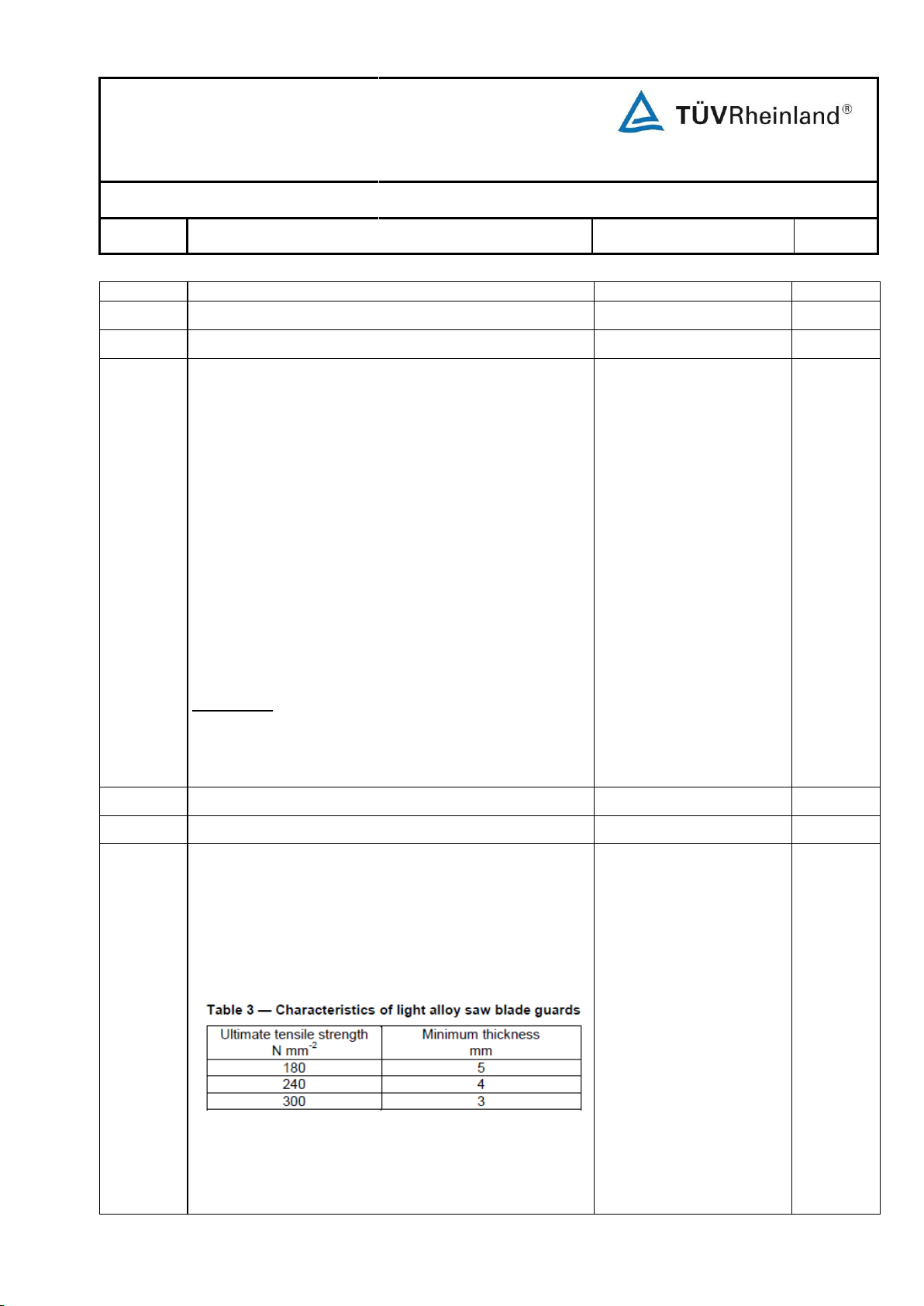
Test Report No.: 17702074 003
Part I of II
Page 12 of 72
EN 1870-19:2013
Clause
Requirement
Remarks - Results
Verdict
functional testing of the machine.
5.3
Protection against mechanical hazards
P
5.3.1
Stability
P
It shall be possible to fix stationary circular saw benches
to a suitable stable structure e.g. floor. Facilities for fixing
are, e.g. fixing holes in the machine frame and the
necessary fixing devices (see 6.3 e)).
Building site saws shall be rigid.
Any displaceable machines shall be stable during
transportation (see also 6.3 h) and i)).
Displaceable machines shall be stable during machining
(see Annex A).
Displaceable machines may have the facility to make
them stable and levelled during machining (e.g. by
providing brakes for the wheels or a device to retract the
wheels from the floor).
Verification: By checking relevant drawings, inspection of
the machine, performing the displaceable machines
stability test of Annex A, performing the building site saw
rigidity test of Annex B and relevant functional testing of
the machine.
Holes for fixing the
machine on the operating
floor are provided on the
machine frame. Instruction
for fixing the machine is
stated in the user manual.
P
5.3.2
Hazard of break up during operation
P
5.3.2.1
General P
Saw blade guard above the
table is made of 3mm thick
polycarbonate.
P
The saw blade guards above the machine table shall be
manufactured from either:
a) steel having an ultimate tensile strength of at least 350
N mm
-2
and a wall thickness of at least 1,5 mm;
b) light alloy with characteristics in accordance with Table
3;
c) polycarbonate with a wall thickness of at least 3 mm or
other plastic material passing the test given in Annex
H.
The saw blade guard below the table shall be
Page 82
Test Report No.: 17702074 003
Part I of II
Page 13 of 72
EN 1870-19:2013
Clause
Requirement
Remarks - Results
Verdict
manufactured from one or a combination of the materials
required in a), b) or c) or from cast iron with an ultimate
tensile strength of at least 200 N mm
-2
and a wall
thickness of at least 5 mm.
Verification: By checking the relevant drawings, tensile
strength, measurement, performing the impact test given
in Annex H for plastic materials other than polycarbonate
and inspection of the machine.
NOTE For the ultimate tensile strength, a confirmation from the
manufacturer of the material can be useful.
5.3.2.2
Avoidance of contact between the saw blades and/or
machine parts
P
The machine shall be designed in such a way that in any
case it is not possible to mount a main saw blade or a
scoring saw blade with a larger diameter than the largest
one for which the machine is designed.
In circular saw bench when a scoring saw blade is
mounted it shall not be possible to mount a main saw
blade that would come in contact with such additional saw
blade taking account of all height adjustment positions of
the saw blades.
Verification: By checking the relevant drawings, inspection
of the machine and relevant functional testing of the
machine.
Checked ok.
P
5.3.3
Tool holder and tool design
P
5.3.3.1
Geometrical performance
P
Saw spindles shall be manufactured in accordance with
the tolerances given in Annex C.
Verification: By checking the relevant drawings and by
measurement.
See annex C.
P
5.3.3.2
Spindle locking
P
When it is necessary to hold the spindle stationary for saw
blade changing, a spindle holding/blocking device shall be
provided, e.g. a double spanner arrangement or an
integral locking bar inserted through the spindle. When a
blocking device is used, it shall prevent tool spindle
rotation and shall not be deformed after starting the
spindle drive motor, with the blocking device in place.
Verification: By checking the relevant drawings, inspection
of the machine, measurement and relevant functional
testing of the machine.
A bar is provided for
locking the spindle. No
deformation occurs when
stating the machine with
the bar in locking position.
P
Page 83
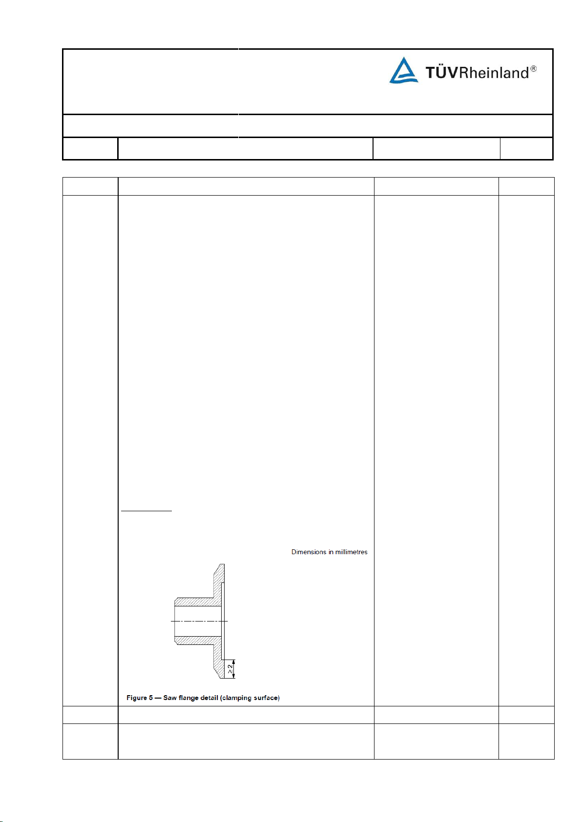
Test Report No.: 17702074 003
Part I of II
Page 14 of 72
EN 1870-19:2013
Clause
Requirement
Remarks - Results
Verdict
5.3.3.3
Saw blade fixing device
P
Saw blade diameter is
254mm.
Diameter of the saw blade
flange is 63.5mm.
Clamping surface is
5.75mm in width.
Outside diameter of both
flanges is identical.
Inside part of the flange is
positive connected with the
saw spindle to prevent
loosing of the saw blade.
P
5.3.3.4
Milling tools for grooving fixing devices
N/A
For circular saw benches with the facility for grooving with
milling tools milling tool flanges shall be provided.
No such function.
N/A
Saw blade flanges (or in the case of flush mounted saw
blades, a flange) shall be provided.
The diameter of each flange shall be at least D/4 (where
D = the diameter of the largest saw blade/scoring saw
blade for which the machine is designed).
For flanges other than those for flush mounted saw
blades, the clamping surface at the outside part of the
flange shall be at least 2 mm in width and the flange(s)
shall be recessed to the centre (see Figure 5).
Where two flanges are provided, both outside diameters
of the clamping surfaces shall be within a tolerance of ± 1
mm.
Loosening the saw blade(s) during start up, running, rundown or braking shall be prevented, e.g. by using a
positive connection between the saw spindle and the saw
blade or by using a positive connection between the front
saw flange and the saw spindle.
Flanged bushes shall be provided where the spindle
diameter is different from the bore size of the saw
blade(s) for which the machine is designed.
Verification: By checking the relevant drawings,
measurement, inspection of the machine and relevant
functional testing of the machine.
Page 84
Test Report No.: 17702074 003
Part I of II
Page 15 of 72
EN 1870-19:2013
Clause
Requirement
Remarks - Results
Verdict
The diameter of the flanges shall be at least 1,4 x bore
diameter of the milling tool.
Loosening of the milling tool shall be prevented, e.g. by
using a positive connection between the front flange and
the spindle.
Verification: By checking the relevant drawings,
measurements and inspection of the machine.
5.3.4
Braking P
5.3.4.1
General P
An automatic brake shall be provided for all tool spindles
with an un-braked run-down time exceeding 10 s (for
measurement of the un-braked run-down time see Annex
I). The braked run-down time shall not exceed 10 s (for
measurement of the braked run down time see Annex I).
A PL of at least c for the braking function shall be
achieved.
In the case of failure of power supply this run-down time
may be exceeded.
The braking torque shall not be applied directly to the tool
itself or to the tool fixing device.
Where a spring operated mechanical brake is fitted the
last paragraph of EN 60204-1:2006, 9.3.4 does not apply
(see 6.3 y)).
For electrical braking, reverse current injection braking
shall not be used.
As an exception where an electrical brake with electronic
control system is fitted, its control system shall be
designed, as a minimum, in PL=b in accordance with the
requirements of EN ISO 13849-1:2008 and be designed
in category 2 in accordance with the requirements of EN
ISO 13849-1:2008 with the exception that the test rate
requirement in EN ISO 13849-1:2008, 4.5.4 is not
applicable. The safety related part of the control circuit for
braking shall be tested periodically, e.g. by monitoring
braked run down time. The feedback shall come from
either the encoder fitted to the spindle motor or from the
measurement of the residual current in the wires
powering the motor.
The test shall:
Mechanical brake is used.
When stops the machine,
the brake operates
automatically. Braking
torque applies to the motor
spindle.
P
Page 85
Test Report No.: 17702074 003
Part I of II
Page 16 of 72
EN 1870-19:2013
Clause
Requirement
Remarks - Results
Verdict
a) be independent from the basic control system for
braking or an internal watch dog shall be provided in
the control system for braking;
b) be independent from the intention of the operator;
c) be performed at each spindle stop.
Where the test result is negative more than three times in
succession, it shall not be possible to operate the
machine. A negative test result shall be indicated.
The diagnostic coverage (DCavg) shall be ≥ 60%.
See Annex E of EN ISO 13849-1:2008 for DC estimation.
As an exception, a simple electronic brake (using simple
electronic parts like rectifiers, transistors, triacs, diodes,
resistors, thyristors) may be PL=b and designed in
category 1 in accordance with the requirements of EN
ISO 13849-1:2008 if the “mean time to a dangerous
failure” (MTTFd) according to Table 5 of EN ISO 138491:2008 reaches a value of “high” (at least 30 years).
NOTE Complex electronic components like e.g.
microprocessors or PLCs cannot be considered as well tried
under the scope of EN ISO 13849-1:2008 and do therefore not
fulfill the requirements of category 1.
For calculating the probability of a dangerous failure for a
simple electronic brake component with no fault detection
(no DC) and no testing capability (category 1) the
procedure described in Annex D of EN ISO 13849-1:2008
can be used.
Verification: By checking the relevant drawings and/or
circuit diagrams, inspection of the machine and relevant
functional testing of the machine. For the determination of
un-braked run-down time and braked run-down time, if
relevant, the appropriate tests given in Annex I apply.
5.3.4.2
Brake release
N/A
Where a control is provided to release the spindle brake
in order to enable rotation by hand and adjustment of the
tool (saw blade, grooving tool), release of the brake shall
only be possible when the spindle has stopped turning
(e.g. by a time delay in accordance with 5.2.1.2 b)
between control actuation and brake release).
It shall not be possible to start the machine before the
No brake release.
N/A
Page 86
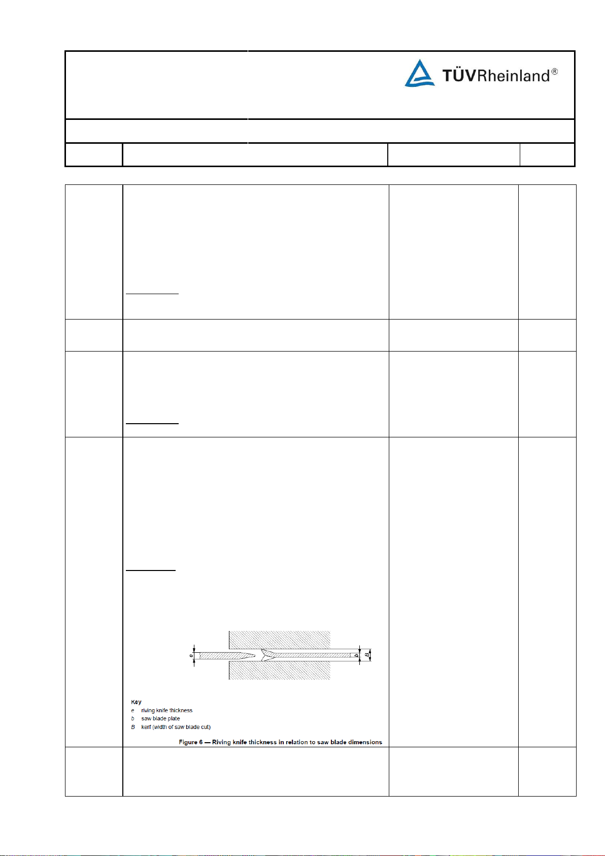
Test Report No.: 17702074 003
Part I of II
Page 17 of 72
EN 1870-19:2013
Clause
Requirement
Remarks - Results
Verdict
control for the spindle brake has been reset. Reset of the
control for brake shall not initiate a start-up of the
machine.
The safety related part of the control system for brake
release shall conform at least to PL=c in accordance with
the requirements of EN ISO 13849-1:2008.
Verification: By checking the relevant drawings, inspection
of the machine and relevant functional testing of the
machine.
5.3.5
Devices to minimize the possibility or the effect of
kickback
P
The machine shall be supplied with a riving knife
mounting arrangement and a riving knife/riving knives to
accommodate the range of saw blades which are
intended for use with the machine (see 6.3 o) and p)).
Verification: By checking the relevant drawings and
inspection of the machine.
Checked ok.
P
UTS of the riving knife:
≥580N/mm2(material 65Mn
steel).
Designed flatness:
≤0.04/100mm.
e=2.2mm, B=3.0mm,
b=2.0mm.
P
b) leading edge of the riving knife shall be chamfered to
provide a "lead-in", and the riving knife shall be of
constant thickness (within ± 0,1 mm) throughout its
working length;
Checked ok.
P
The riving knife and its mounting arrangement shall be in
accordance with the following requirements:
a) riving knives shall be manufactured from steel with an
ultimate tensile strength of 580 N mm-2 or of a
comparable material, have flat sides (within 0,2 mm per
100 mm) and shall have a thickness less than the width
of cut (kerf) and at least 0,2 mm greater than the saw
blade plate (see Figure 6);
Verification: By checking the relevant drawings and
measurement.
NOTE For the tensile strength a confirmation from the
manufacturer of the material can be useful.
Page 87
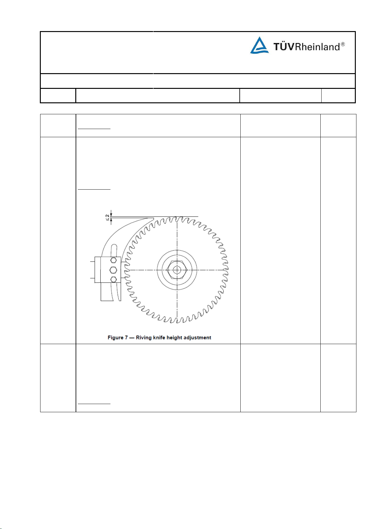
Test Report No.: 17702074 003
Part I of II
Page 18 of 72
EN 1870-19:2013
Clause
Requirement
Remarks - Results
Verdict
Verification: By checking the relevant drawings, inspection
of the machine and measurement.
Checked ok
P
d) riving knife shall be designed so that when it is
mounted and adjusted so that its closest point to the
saw blade is 3 mm, then at no point shall the gap
between the saw blade and the riving knife be greater
than 8 mm, measured radially through the centre of the
saw spindle in the area above the table (see Figure 8);
Verification: By checking the relevant drawings, inspection
of the machine and measurement.
Checked ok
P
c) riving knife shall be capable of vertical adjustment so
that its tip reaches a level 2 mm below the highest point
on the periphery of the saw blade or higher when set in
accordance with the requirements of 5.3.5 d) (see
Figure 7) (also see 6.3 l));
Verification: By checking the relevant drawings, inspection
of the machine and measurement.
Page 88
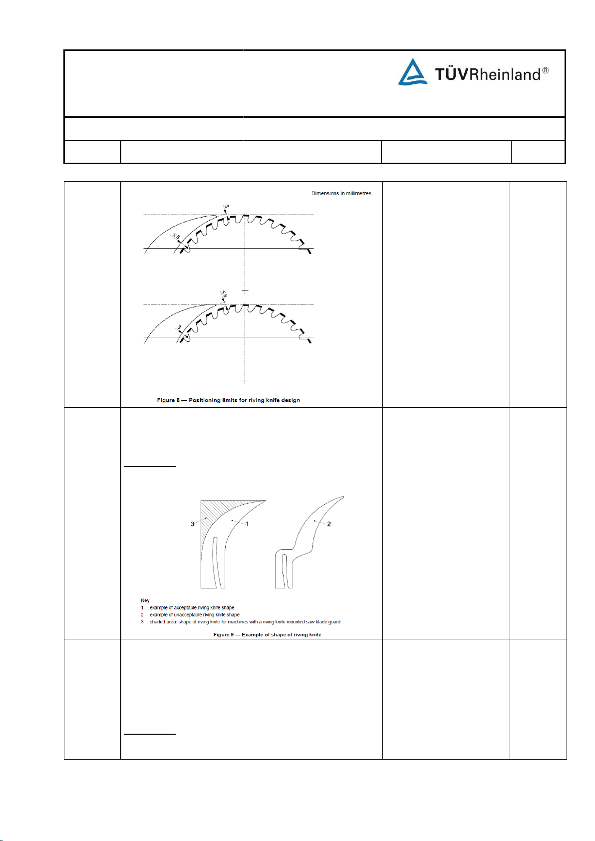
Test Report No.: 17702074 003
Part I of II
Page 19 of 72
EN 1870-19:2013
Clause
Requirement
Remarks - Results
Verdict
Checked ok.
P
f) riving knife mounting arrangement shall be such that
the relative position of the riving knife and the rear saw
flange is in accordance with the tolerance shown in
Figure 10. The relative position of the riving knife and
the rear saw blade flange shall be maintained with the
rise, fall and tilt of the saw blade;
Verification: By checking the relevant drawings, inspection
of the machine, measurement and relevant functional
testing of the machine.
Checked ok
P
e) front and rear contours of the riving knife shall be
continuous curves or straight lines, without any flexure
which would weaken it (e.g. see Figure 9);
Verification: By checking the relevant drawings and
inspection of the machine.
Page 89
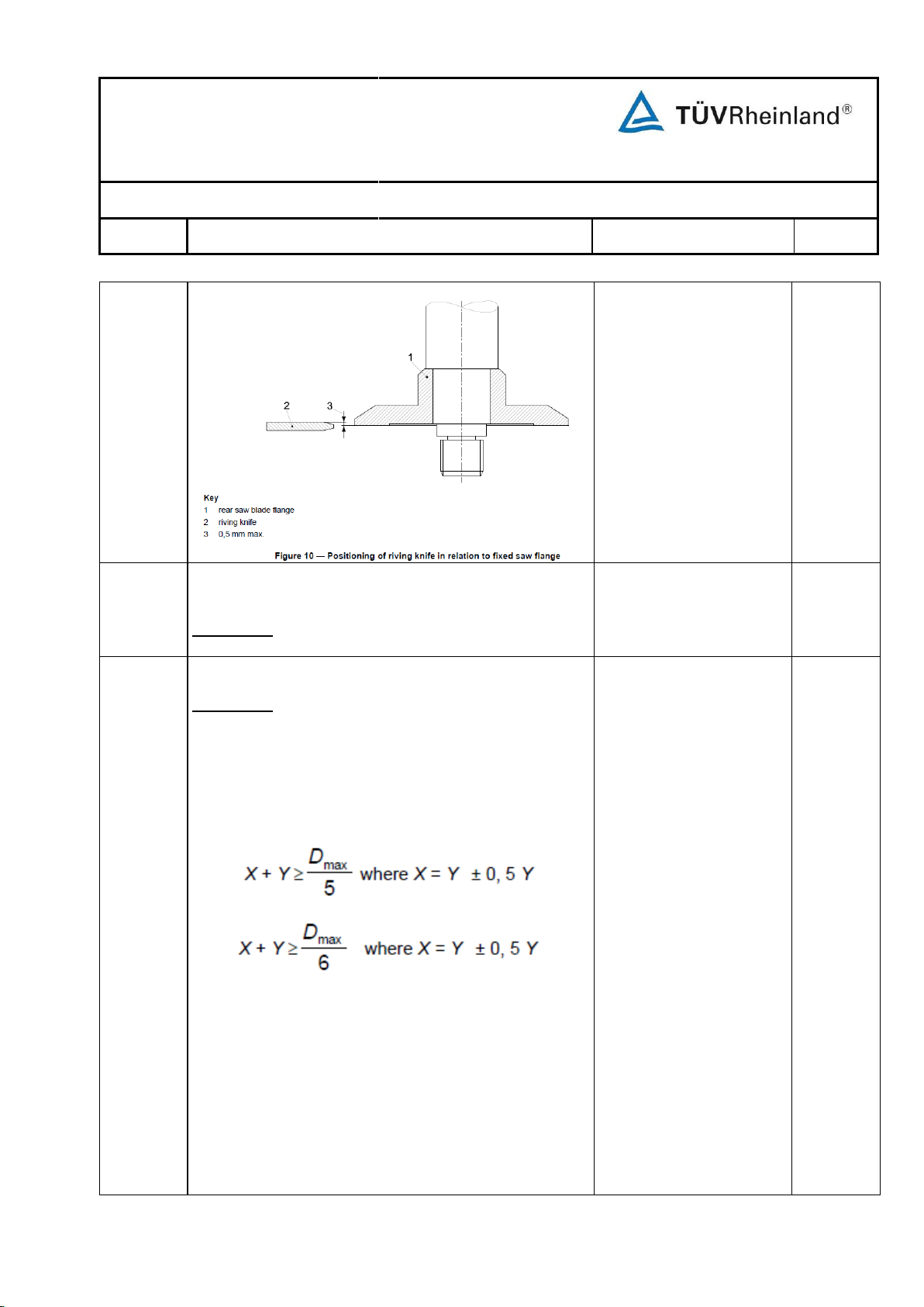
Test Report No.: 17702074 003
Part I of II
Page 20 of 72
EN 1870-19:2013
Clause
Requirement
Remarks - Results
Verdict
g) arrangement for fixing the riving knife shall be
longitudinally stable;
Verification: By checking the relevant drawings and
carrying out the stability test in accordance with Annex D.
See annex D.
P
Conform with the
requirement of annex E.
P
h) riving knife and its mounting shall be laterally stable;
Verification: Perform the stability test shown in Annex E
or stability is ensured if the width of the riving knife on
each side of the fixing slot within the fixing area is
designed in accordance with the following formulae
(see Figure 11):
For riving knives supporting a saw guard:
For riving knives not supporting a saw guard:
where
Dmax is the maximum saw blade diameter for
which the riving knife can be used.
X and Y shall be measured midway along the riving knife
fixing slot in the fixing area (see Figure 11).
The riving knife fixing plates' dimensions shall not be
lower than the total width of the riving knife in the fixing
area minus 2 mm.
Page 90
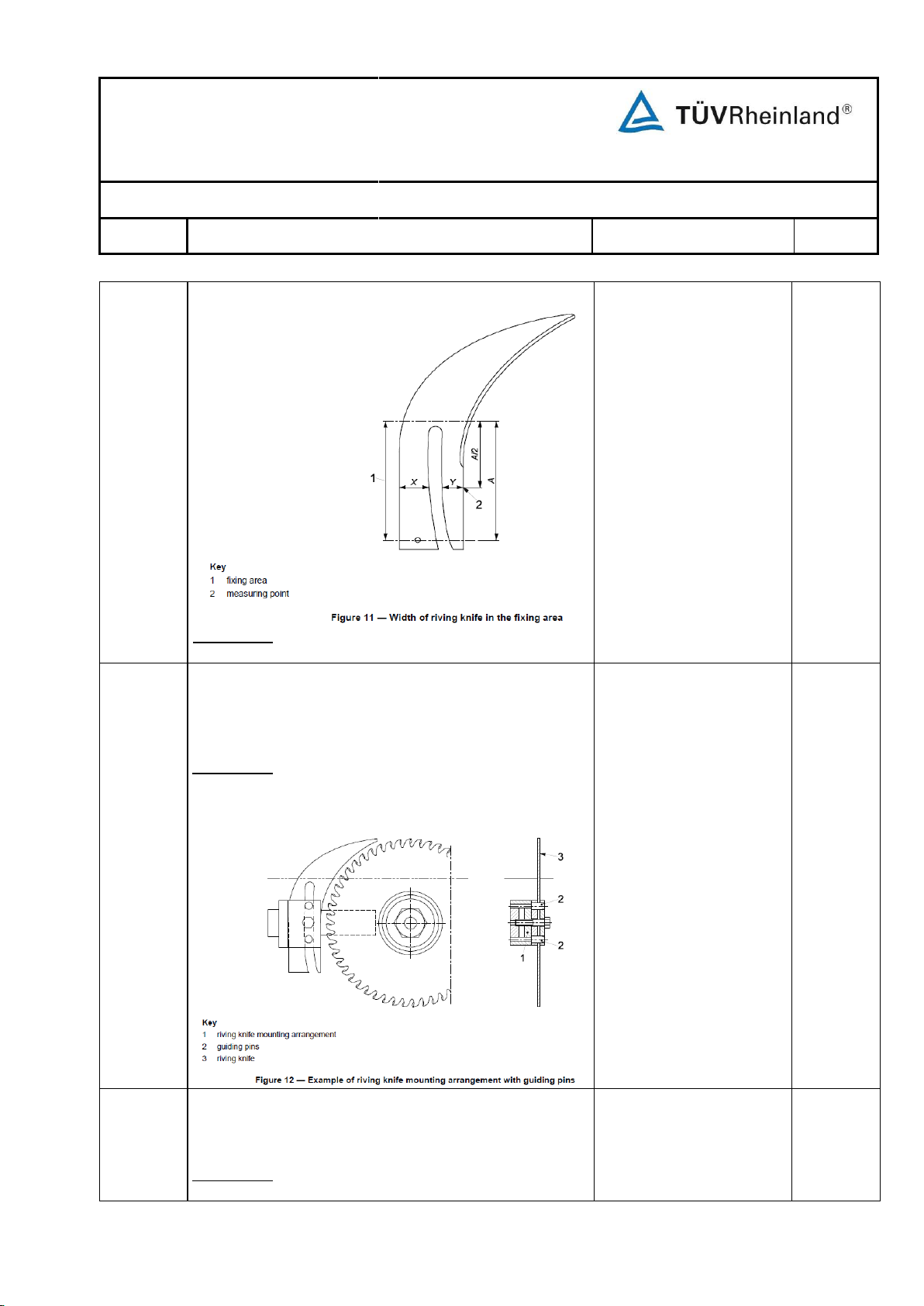
Test Report No.: 17702074 003
Part I of II
Page 21 of 72
EN 1870-19:2013
Clause
Requirement
Remarks - Results
Verdict
Checked ok
P
j) where it is necessary to change the riving knife to
accommodate different diameters of saw blade, the
riving knife fixing slot shall be open ended.
Verification: By checking the relevant drawings and
inspection of the machine.
Checked ok.
P
Verification: By checking the relevant drawings, inspection
of the machine and measurement.
i) riving knife shall be held in position by guiding elements,
e.g. guiding pins (see Figure 12). The riving knife fixing
slot shall be no more than 0,5 mm wider than the
guiding elements;
Verification: By checking the relevant drawings, inspection
of the machine and measurement.
Page 91
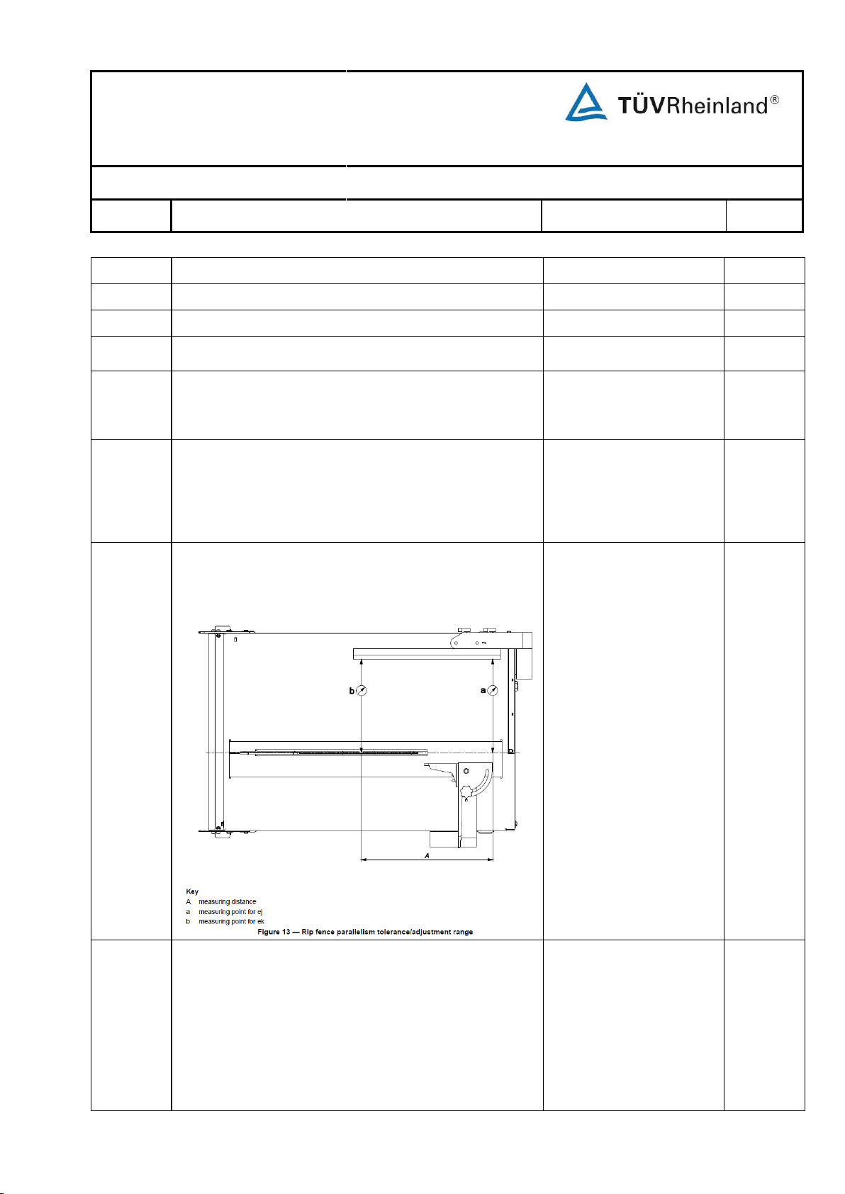
Test Report No.: 17702074 003
Part I of II
Page 22 of 72
EN 1870-19:2013
Clause
Requirement
Remarks - Results
Verdict
5.3.6
Workpiece supports and guides
P
5.3.6.1
Workpiece guides and fences
P
5.3.6.1.1
Rip fence
P
The machine shall be fitted with an adjustable rip fence to
allow the cutting of different workpiece widths.
P
The workpiece guiding part of the rip fence shall:
a) be made from plastic, light alloy or wood if there is a
possibility of contact with the saw blade;
Made of aluminium alloy.
P
b) be adjustable in the direction of the cutting line so that
its out-feed end can be moved forward to a point in line
with the front edge of the riving knife, and rearwards to
a point at table level which is in line with the first cutting
tooth of the largest saw blade for which the machine is
designed and adjusted to the maximum cutting height;
Checked ok.
P
Checked ok.
P
d) be either:
1) manufactured from a single component, having two
guiding surfaces one with a high position for deep
cutting and the other with a low position for shallow
or angled cutting (see Figure 14), or
2) consist of two components, one, with a high guiding
surface for deep cutting and the other with a low
guiding surface for shallow or angled cutting. These
The rip fence has two
guiding surfaces. Details
see below.
P
c) after adjustment, remain in a vertical plane and be
parallel to the cutting line of the saw blade where a
deviation ek > ej from exact parallelism is necessary in
order to prevent jamming (see Figure 13);
Page 92
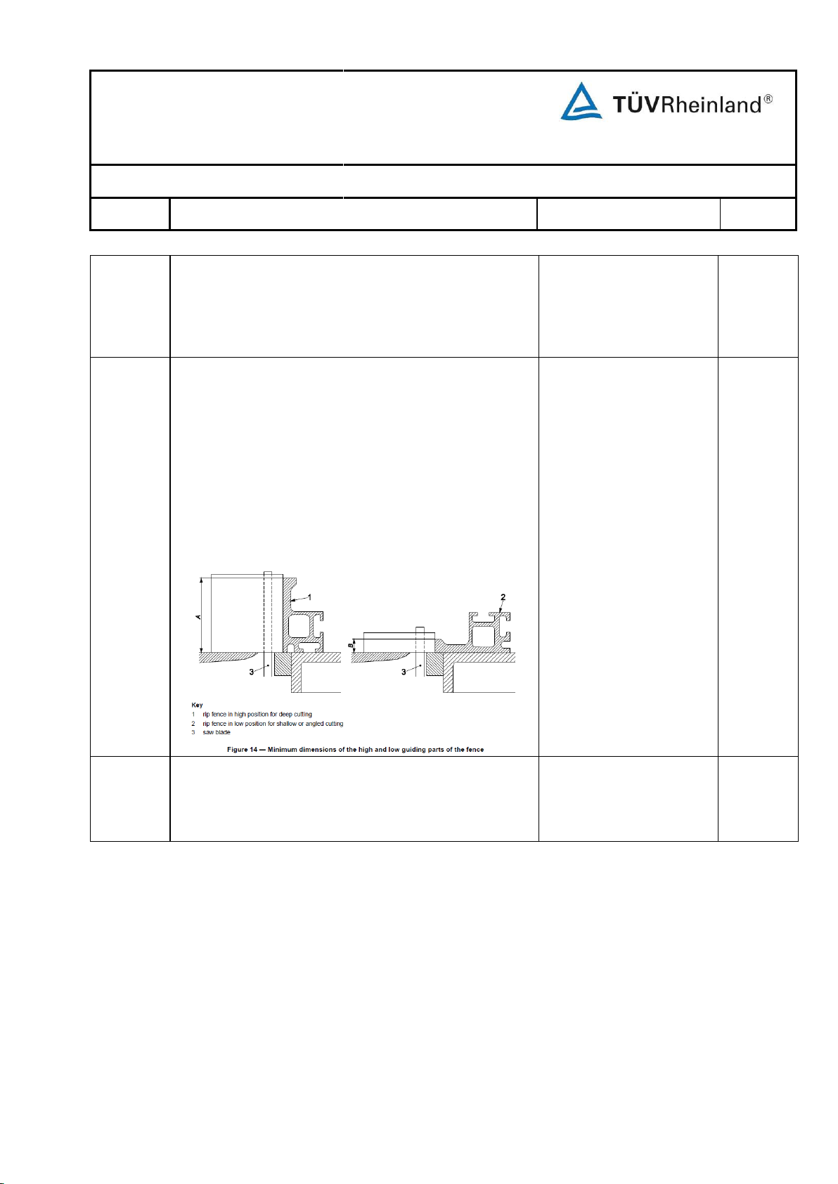
Test Report No.: 17702074 003
Part I of II
Page 23 of 72
EN 1870-19:2013
Clause
Requirement
Remarks - Results
Verdict
components shall not be capable of being fitted to
the support at the same time except in the case of
machines with a maximum saw blade diameter of
200 mm, where they may consist of two parts which
can be fitted together but shall be removable
without the aid of a tool;
between 5 mm and 15 mm in its low
A=65mm. B=14mm. (Max.
saw blade diameter:
254mm.)
P
f) be so designed that when it is in the low position, the saw
blade shall not be capable of touching the rip fence at
point A as shown in Figure 15 when the saw blade is fully
tilted;
Checked ok.
P
e) have a height B
position (see Figure 14) and in its high position a
minimum height A of the workpiece guiding part of:
1) A ≥ 90 mm with saw blades with a diameter > 315
mm;
2) A ≥ 50 mm with saw blades with a diameter ≤ 315
mm;
3) A ≥ 30 mm with saw bl ades with a diameter ≤ 200
mm.
Page 93
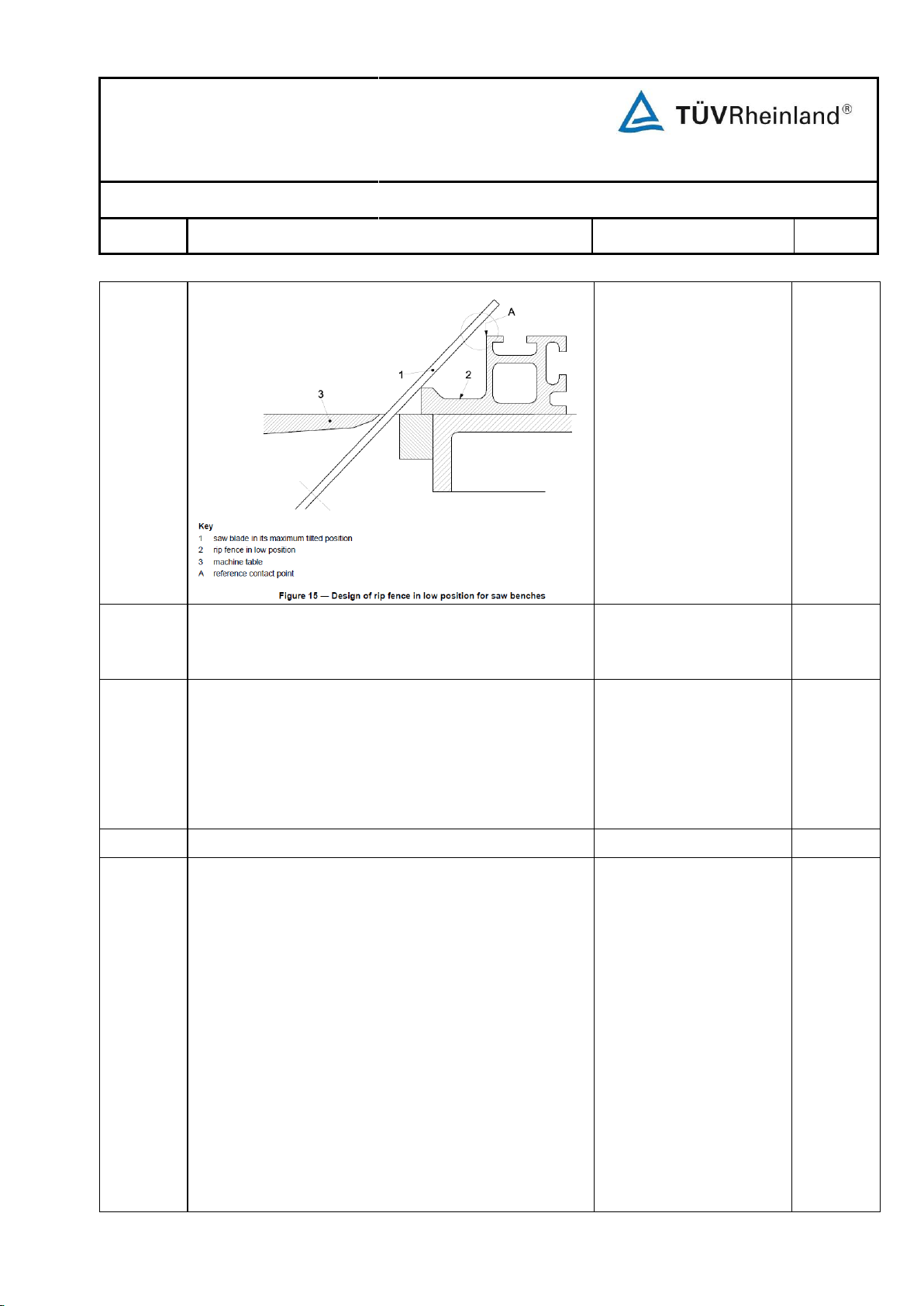
Test Report No.: 17702074 003
Part I of II
Page 24 of 72
EN 1870-19:2013
Clause
Requirement
Remarks - Results
Verdict
g) be so designed that when it is in the low position, the
saw guard can be lowered to the minimum height of the
workpiece guiding part of the fence.
Checked ok.
P
Adjustment and fixing of the rip fence position shall be
possible without the aid of a tool.
Also see 5.3.7.
Verification: By checking the relevant drawings,
measurement, inspection of the machine and relevant
functional testing of the machine.
Checked ok.
P
5.3.6.1.2
Cross-cutting fence
P
The circular saw benches and building site saws shall be
equipped with a cross-cutting fence (fixed to a sliding
table or movable) (e.g. see Figure 1 and Figure 2), and
the fixing arrangement shall ensure that the fence cannot
lift up or swing out of position during use (e.g. see Figure
16). If the cross-cutting fence extends beneath the saw
guard then the height of that section shall not exceed 15
mm.
If the workpiece guiding part of the cross-cutting fence is
adjustable in length and if there is a possibility of contact
between the cross-cutting fence and the saw blade, this
part of the fence shall be made chipable material, e.g.
polypropylene, polyamide, polyethylene or other plastics
with similar characteristics, light alloy, wood, plywood or
brass.
Adjustment and fixing of the cross-cutting fence position
shall be possible without the aid of a tool.
End height of the crosscutting fence extends
beneath the top guard of
the saw blade is 10mm.
“T” slot used as guiding of
the fence.
The cross cutting fence is
made of aluminium and it
end close to the sow blade
is plastic.
Checked ok.
P
Page 94
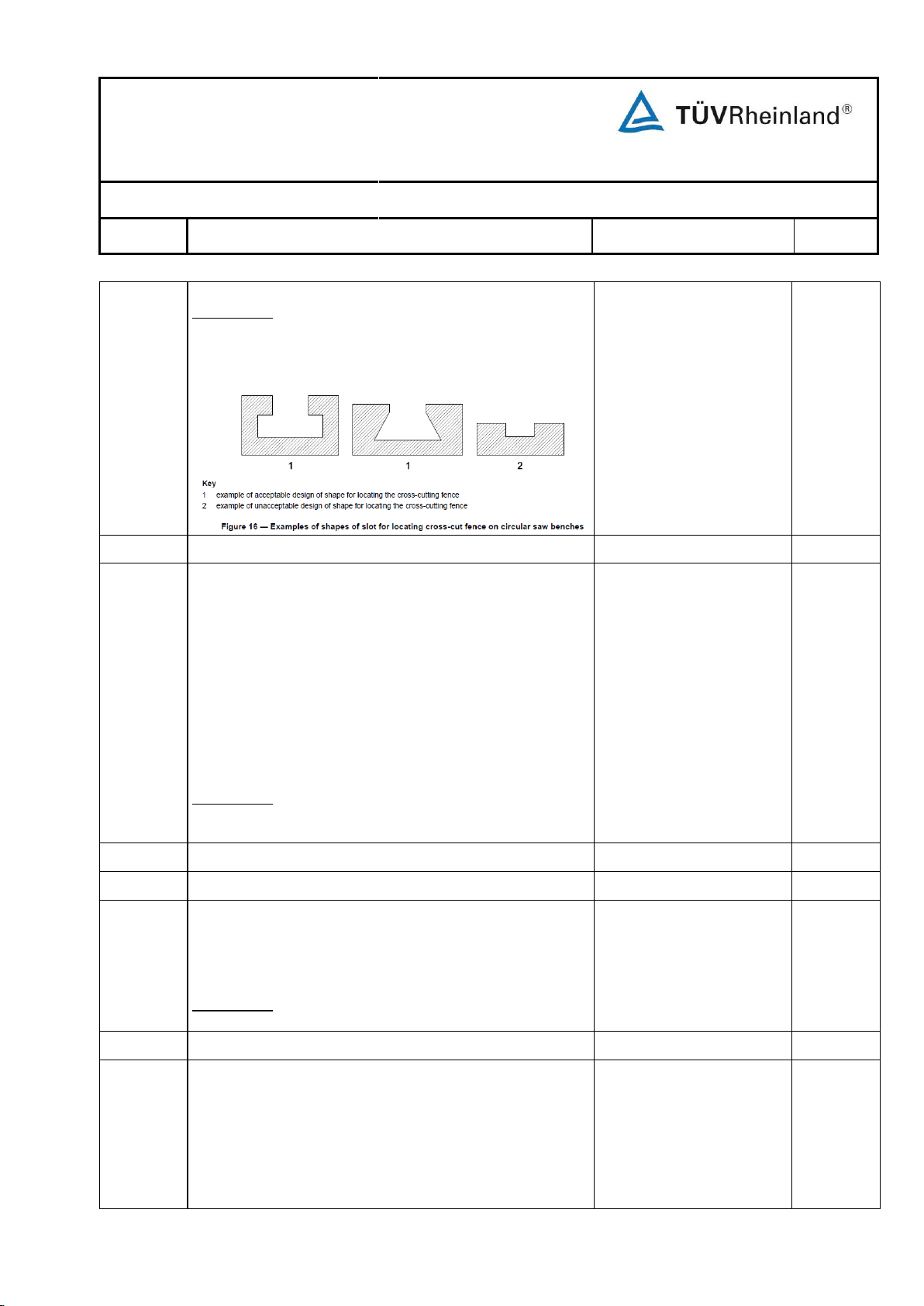
Test Report No.: 17702074 003
Part I of II
Page 25 of 72
EN 1870-19:2013
Clause
Requirement
Remarks - Results
Verdict
5.3.6.1.3
Wedge cutting device
N/A
The building site saw shall be equipped with an integral
wedge cutting device (e.g. as shown in Figure 3). This
device shall be so designed that any part which may be in
contact with the saw blade shall be made of plastic, light
alloy or wood. This device may be combined with the
cross cutting fence.
Adjustment and fixing of the integral wedge cutting device
position shall be possible without the aid of a tool.
See also 5.3.8 and Figure 31.
Verification: By checking the relevant drawings, inspection
of the machine and relevant functional testing of the
machine.
Circular saw bench.
N/A
5.3.6.2
Workpiece tables
P
5.3.6.2.1
Machine table
P
The dimensions of the machine table shall be in
accordance with the requirements of Table F.1 for circular
saw benches and of Table F.2 for building site saws (see
Annex F).
Verification: By checking the relevant drawings, inspection
of the machine and measurement.
See annex F.
P
5.3.6.2.2
Extension table
P
The machine shall be provided with either a table or with
an extension table such that the distance between the
centre line of the saw spindle and the far end of the table
or extension table is in accordance with the requirements
of Annex F.
On building site saws the extension table shall be capable
of being folded away whilst remaining attached to the
See annex F.
Verification: By checking the relevant drawings,
measurement, inspection of the machine and relevant
functional testing of the machine.
Page 95
Test Report No.: 17702074 003
Part I of II
Page 26 of 72
EN 1870-19:2013
Clause
Requirement
Remarks - Results
Verdict
machine.
Verification: By checking the relevant drawings, inspection
of the machine and measurement.
5.3.7
Prevention of access to moving parts
P
5.3.7.1
Access to the saw blade above the machine table
P
5.3.7.1.1
General P
Access to the saw blade(s) above the machine table shall
be prevented by a manually adjustable or automatically
adjustable saw blade guard either fit to the riving knife or
to the machine separately from the riving knife.
The saw blade guard shall be in accordance with the
following requirements:
a) it shall be designed to encompass the saw blade(s)
and scoring saw blade (when fitted), and shall extend
beyond the first cutting tooth at the table top level when
the saw blade and/or scoring saw blade is adjusted to
its highest position;
Verification: By checking the relevant drawings,
inspection of the machine and relevant functional
testing of the machine.
b) it shall be rigid;
Verification: By checking the relevant drawings and
carrying out the rigidity test in accordance with Annex
G.
c) the lower inner edges of the sides of the saw blade
guard shall be lined with a rib, made of plastic, light
alloy, wood or wood based materials. This rib shall be a
minimum 3 mm in width, and shall be designed so as
to prevent the saw blade teeth from cutting into the saw
blade guard should the saw blade guard be displaced
from the line of cut (see Figure 17). If the rib is
replaceable, the fixing arrangement shall be such that it
does not damage the saw blade e.g. brass screws;
Verification: By checking the relevant drawings,
inspection of the machine, measurement and relevant
functional testing of the machine.
Manually adjustable guard
fitted to the riving knife is
provided.
Checked ok.
See annex G.
The guard is made of PC.
Rip width is 4mm
P
Page 96
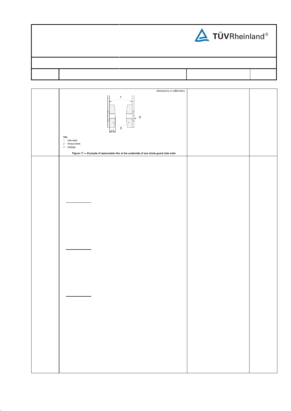
Test Report No.: 17702074 003
Part I of II
Page 27 of 72
EN 1870-19:2013
Clause
Requirement
Remarks - Results
Verdict
d) whatever the pre-set adjusted position of the saw blade
guard, it shall be capable of upward movement during
the cutting operation as a function of variations in
workpiece thickness and may or may not return to the
pre-set adjusted position for this type of guard at the
end of the cutting operation;
Verification: By checking relevant drawings, inspection
of the machine and relevant functional testing of the
machine.
e) If a manual adjustable saw blade guard is provided the
height adjustment shall be possible without the aid of a
tool;
Verification: By checking relevant drawings, inspection
of the machine and relevant functional testing of the
machine.
f) on non-transparent saw blade guards, the line of cut
shall be indicated, for example by a groove moulded
into the saw blade guard;
Verification: By checking the relevant drawings and
inspection of machine.
g) on machines which are designed to be used with saw
blade diameters of ≤ 315 mm the saw blade guard shall
be automatically adjustable or manually adjustable in
height and mounted either on the riving knife (see
Figure 18), or separately from the riving knife. In the
latter case it shall be designed for integral mounting to
the machine (see Figure 1). When mounted separately
from the riving knife but integral with the machine, the
support for the saw blade guard shall not be in line
behind the riving knife;
Checked ok.
Checked ok.
Transparent guard is used.
Mounted on the riving
knife.
P
Page 97
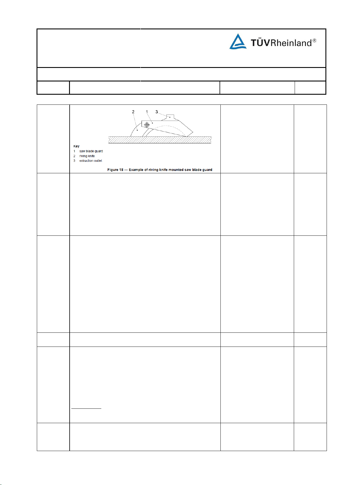
Test Report No.: 17702074 003
Part I of II
Page 28 of 72
EN 1870-19:2013
Clause
Requirement
Remarks - Results
Verdict
h) on saw benches which are designed to be used with
saw blade diameters of > 315 mm, the saw blade
guard shall be an automatically adjustable guard or a
manually adjustable guard adjustable in height and
mounted separately from the riving knife. The support
for the saw blade guard shall be designed for integral
mounting to the machine (see Figure 1). When the
support is an integral part of the machine it shall not be
in line behind the riving knife;
N/A
i) on circular saw bench fitted with the facility for
grooving, the saw blade guard shall be mounted
separately from the riving knife independently from the
maximum diameter of the saw blades. For each
grooving operation the tool (either saw blade or milling
tool) shall be covered from above access, either by
saw blade guard mounted separately from the riving
knife or by providing the mountings for a protecting
device mounted on the parallel fence (see 5.3.9 and
6.3 b)
Verification: By checking the relevant drawings, inspection
of the machine and relevant functional testing of the
machine.
N/A
5.3.7.1.2
Additional requirements for riving knife mounted saw
blade guards
P
Access to the top and sides of the exposed saw teeth
shall be prevented from the guard mounting point on the
riving knife to the first cutting tooth at the machine table
level for all intended saw blade diameters and highest
vertical position of the saw blade. It may be necessary to
provide more than one fixing point on the riving knife in
order to achieve this requirement.
Verification: By checking the relevant drawings, inspection
of the machine and relevant functional testing of the
machine.
Checked ok.
It shall be possible to fix the saw blade guard on the riving
knife in such a way that work piece jamming is avoided if
the saw blade guard is raised to its highest position. This
requirement shall be met independent of the height
Checked ok.
P
Page 98
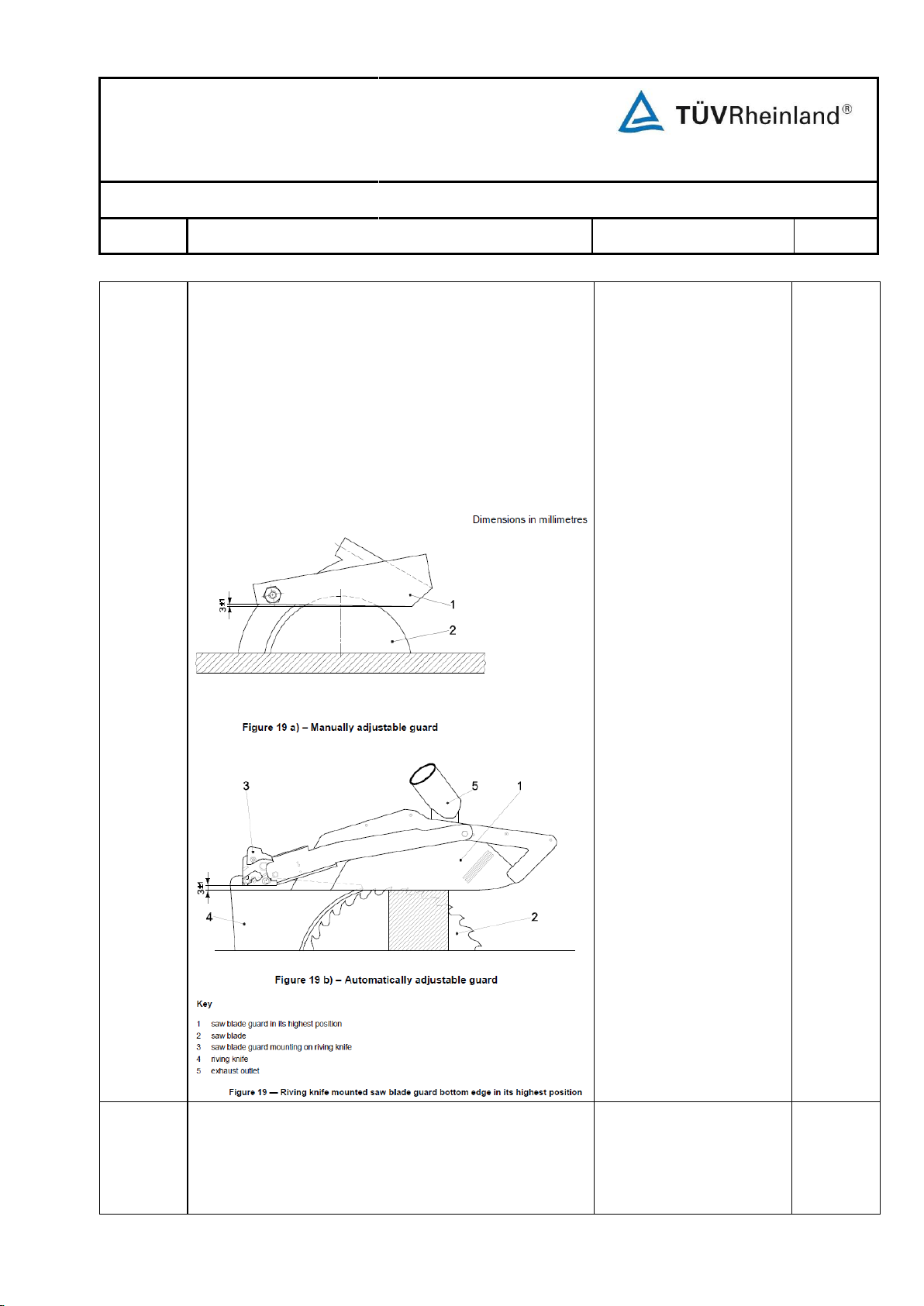
Test Report No.: 17702074 003
Part I of II
Page 29 of 72
EN 1870-19:2013
Clause
Requirement
Remarks - Results
Verdict
The in-feed end of the base of the saw blade guard shall
have a “lead-in” in order to avoid misfeeding should the
saw blade guard be incorrectly set or the workpiece be
uneven. If the saw unit is fitted with the maximum saw
blade and raised to the maximum cutting depth and the
saw blade guard is lowered to the machine table the lead
Max. cutting height 77mm.
H=30mm
α =42°.
P
position of the saw blade (see Figure 19).
When necessary the correct vertical position of the riving
knife to fulfil this requirement has to be indicated, e.g. by
a marking on the riving knife in the level of the machine
table. The maximum cutting height shall be less than the
maximum saw blade projection above the table.
The mounting and dismounting of saw blade guard on the
riving knife shall be possible without the aid of a tool.
Page 99
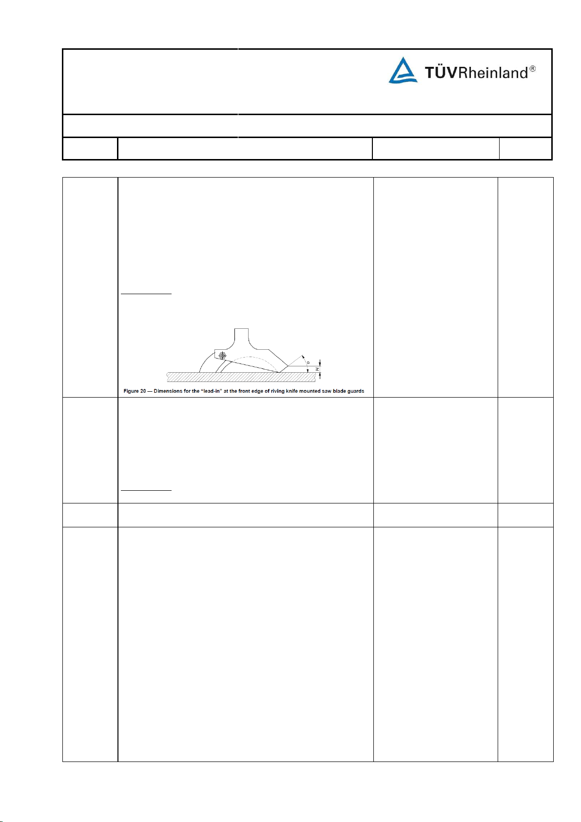
Test Report No.: 17702074 003
Part I of II
Page 30 of 72
EN 1870-19:2013
Clause
Requirement
Remarks - Results
Verdict
In the area where the saw guard can come in contact with
the rip fence in the higher position the maximum width of
the saw blade guard shall not exceed 40 mm.
The maximum width of the saw blade guard on the fence
side shall be 15 from the saw blades flange (see Figure
23):
Verification: By checking the relevant drawings and
measurement.
Width of guard:30mm
Width of the saw blade
guard on the fence side
13.8mm.
P
5.3.7.1.3
Additional requirements for saw blade guards
mounted to the table separately from the riving knife
N/A
When mounted separately from the riving knife, the saw
blade guard shall be in accordance with the following
requirements:
a) it shall prevent access to the top and both sides of the
saw blade, when the saw blade is in the vertical
position;
b) it shall be adjustable in height from the table level up to
a maximum height of 5 mm above the uppermost saw
teeth when the machine is fitted with the largest saw
blade for which it is designed;
c) means of adjustment shall ensure that the bottom of
the saw blade guard remains parallel to the table at all
times (within 1 mm for every 100 mm length);
d) it shall be fitted with a device for easily adjusting the
height of the saw blade guard, e.g. a handle or the
push stick positioned in a holder on the saw blade
N/A
in shall be in accordance with the following requirements:
a) minimum height H (see Figure 20) shall be such, that
the saw blade guard can be raised by a workpiece with
a thickness of 20 % of the maximum cutting depth for
which the machine is designed;
b) angle α shall be not more than 45°.
Verification: By checking the relevant drawings,
measurement and inspection of the machine.
Page 100
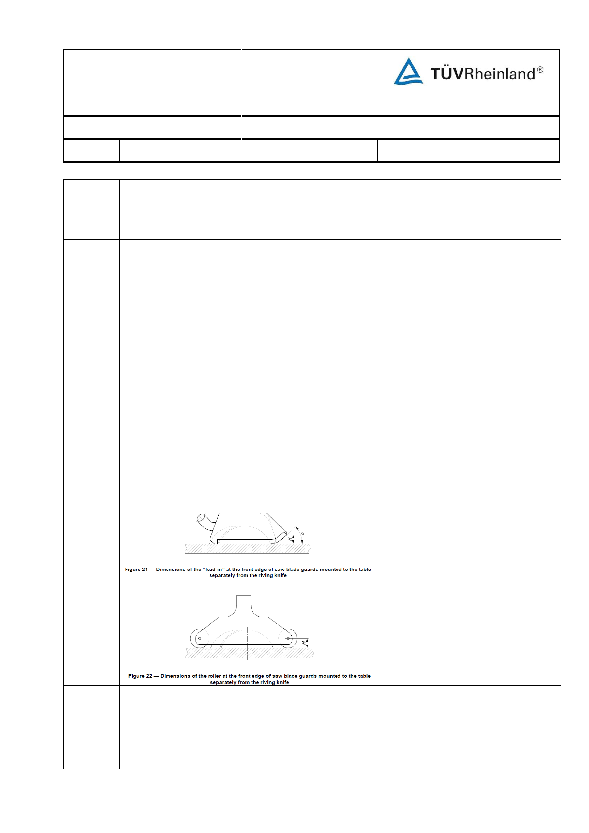
Test Report No.: 17702074 003
Part I of II
Page 31 of 72
EN 1870-19:2013
Clause
Requirement
Remarks - Results
Verdict
guard;
e) when it is adjusted to its lowest position, the height of
the saw blade shall be visible from the point at which
the operator adjusts the saw blade height;
N/A
When an automatic adjusting saw blade guard is provided
it shall prevent completely access to the saw blade when
the operator is not feeding a workpiece and be capable of
automatic upward movement during cutting operation
without jamming of the workpiece e.g. by a 3 rollers
climber at the front edge of the saw blade guard mounted
separately from the riving knife.
N/A
f) in feed and out feed ends of its base shall be designed
to allow upward vertical movement of the saw blade
guard in order to avoid misfeeding should the saw
blade guard be incorrectly set or the workpiece be
uneven. This can be achieved for example by:
1) providing of “lead-ins”. The front lead-in shall be in
accordance with the following requirements (see
Figure 21):
i) minimum height H shall be such, that the saw
blade guard can be raised by a workpiece with a
thickness of 20 % of the maximum cutting depth
for which the machine is designed;
ii) angle α shall be not more than 45°; or
2) equipping the saw blade guard with rollers (see Figure
22). The minimum radius H of the rollers shall be such,
that the saw blade guard can be raised by a workpiece
with a thickness of 20 % of the maximum cutting depth
for which the machine is designed.
 Loading...