

Page 1
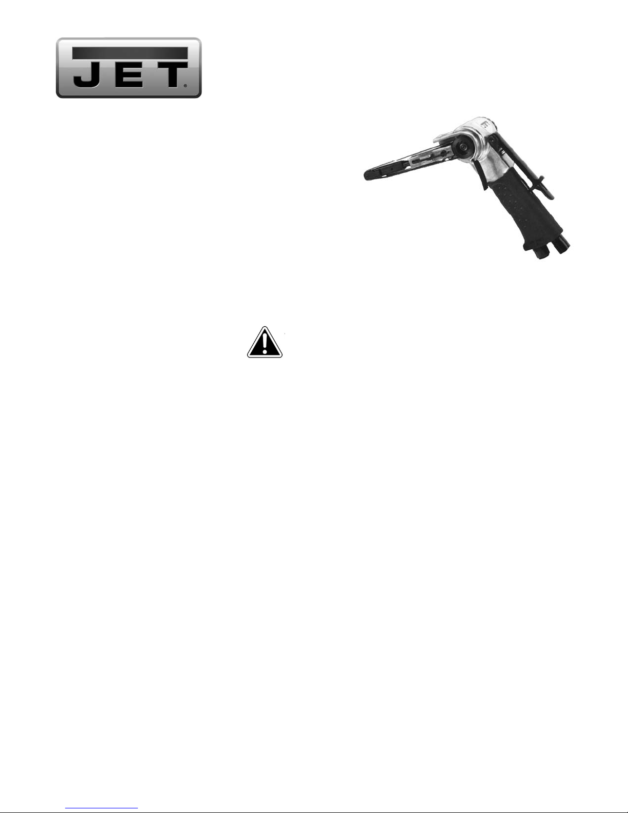
JSM-6100 Belt Sande
r
Stock No. JSM-6100
Specifications
Stock Number ................................................................... JSM-6100
Belt Size (in.) ......................................................................... 3/8 x 13
Noise Level (dB) ............................................................................ 80
Horsepower (HP) .......................................................................... 1/2
Free Speed (RPM) ................................................................. 20,000
Surface Feet per Minute (SFPM) ............................................... 4,328
Required Air Pressure (PSI) ........................................................... 90
Average Air Consumption (CFM) ...................................................... 9
Air Inlet (in.) .......................................................................... 1/4 NPT
Air Hose Inside Diameter (in.) ....................................................... 3/8
Overall Length Folded (in.) ............................................................... 8
Overall Length Open (in.) ......................................................... 12-3/4
Vibration Value (m/s
Weight (lbs) ............................................................................... 1-7/8
The sp ecifications in this manual wer e current at time o f publicat ion, but b ecause of our policy of contin uous improv ement, W alter Meier
(Manufacturing) Inc., reserves the right to change specifications at any time and without prior notice, without incurring obligations.
1. Read and understand the entire contents of this manual before attempting operation.
2. Never operate a belt sander without proper eye and face protection.
3. Do not operate sander while wearing gloves, loose clothing, jewel ry or anything that may get caught in a rotating belt.
Long hair must be contained.
4. Wear ear protectors (plugs or muffs) during ext ended periods of operation.
5. Do not operate sander over 100 PSI.
6. Do not operate sander without the silencer (muffler) installed.
7. Keep hands and fingers away from sanding bel t.
8. Disconnect sander from air sour ce before making repairs, adjustments or belt changes.
9. Some dust created by power sanding, sawing, grinding, drilling and other construction activities contain chemi c als known
to cause cancer , birth defects or other reproductive harm. Some examples of these chemicals are:
• Lead from lead based paint.
• Crystalline silica from bricks, cem ent and other masonry products.
• Arsenic and chrom ium fr om chem ically tr eated lumber.
Your risk of exposure varies, depending on how often you do this type of work. To reduce your exposure to these
chemicals, work in a well-ventilated area and work with approved safety equipment, such as face or dust masks that are
specifically designed to filter out microscopic par ticles.
10. Use the right tool at the correct speed and feed rate. Do not force a tool or attachment to do a job for which it was not
designed. Th e ri g ht t o ol will do the j ob b etter a n d mor e safely.
11. Use recommended accessor ies; improper accessories may be hazardous.
12. Don’t use in dangerous environment. Don’t use power tools in damp or wet location, or expose t hem to rain. Keep work
area well lighted.
13. Failur e to comply with all of the above warnings m ay lead to serious injury.
WALTER MEIER (Manufacturing), Inc.
427 New Sanford Road
LaVergne, Tennessee 37086 Part No. M-JSM-6100
Ph.: 800-274-6848 Revision A1 08/2013
www.waltermeier.com Copyright © 2013 Walter Meier (Manufacturi ng), Inc.
2
) ................................................................... 1.3
Safety warnings
1
Page 2
Operating conditions
• Compressor must be able to deliver 9 CFM, at 70
to 100 PSI.
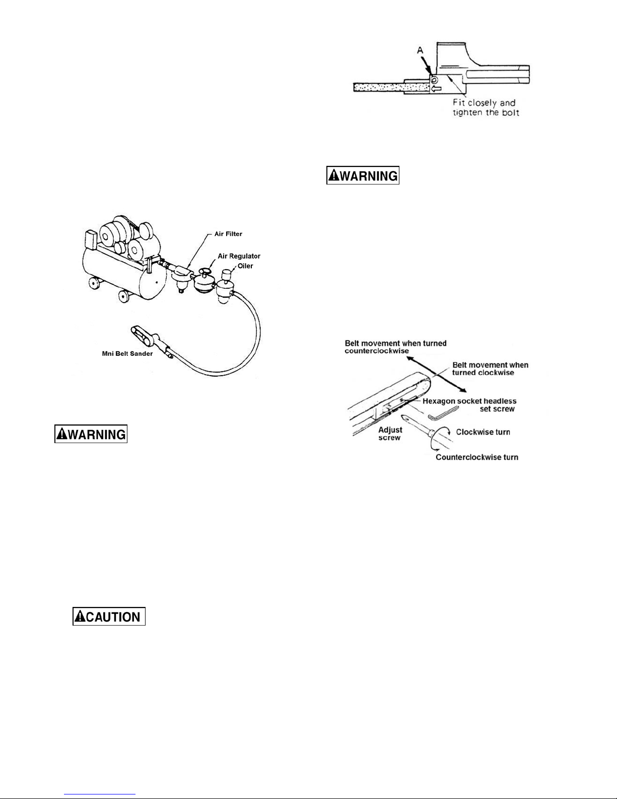
• Use 3/8” air hose between the compres sor and t he
sander.
• To avoid moisture damage to the sander, use an
inline filter to trap moisture and an inline oiler to
keep the sander running at top efficiency. These
are placed inline between t he compressor and the
sander. See Figure 1.
For further information, see “Air Tools – Instruction a nd
Care” enclosed with the sander.
Figure 2
Tracking adjustment
Tracking adjustment requires the
sander to be connected to the hose and running.
Use caution when hands and tools are close to a
running belt. Failure to comply may cause serious
injury.
Belt is tracking properly on all models when centered
on the idle pulley.
1. Loosen set screw with wrench. See Figure 3.
2. With belt running, turn adjusting screw clockwise or
counterclockwise until it is centered on the idler
pulley.
3. Tighten set screw.
Figure 1
Before operation
Disconnect sander from air hose
before making any repair or adjustment. Failure to
comply may cause serious injury.
1. Run compressor and blow out hose before
connecting sander, to clear line of any
contaminants.
2. Before connecting the hose to t he sander, add 4 to
5 drops of air tool oil to the air inlet.
3. If an inline oiler is not used, add 4 to 5 drops at the
air inlet for every three to four hours of operation.
4. Adjust head to desired angle and tighten hex
socket cap screw (A, Figure 2), with hex wrench
supplied.
Always tighten hex socket cap
screw firmly after adjustment, or the head
could rotate causing loss of control.
Figure 3
Belt replacement
1. Disconnect sander from air source.
2. Loosen hex cap screw (A, Figure 2), turn head 90degrees to the handle, and tighten screw to lock.
See Figure 4.
3. Steady the sander with one hand while pushing
down on the idle wheel assembly with the other
until assembly locks in place. See Figure 4.
4. Remove old belt. Install new belt.
5. Press safety lever (A, Figu re 4) to tension belt.
2
Page 3
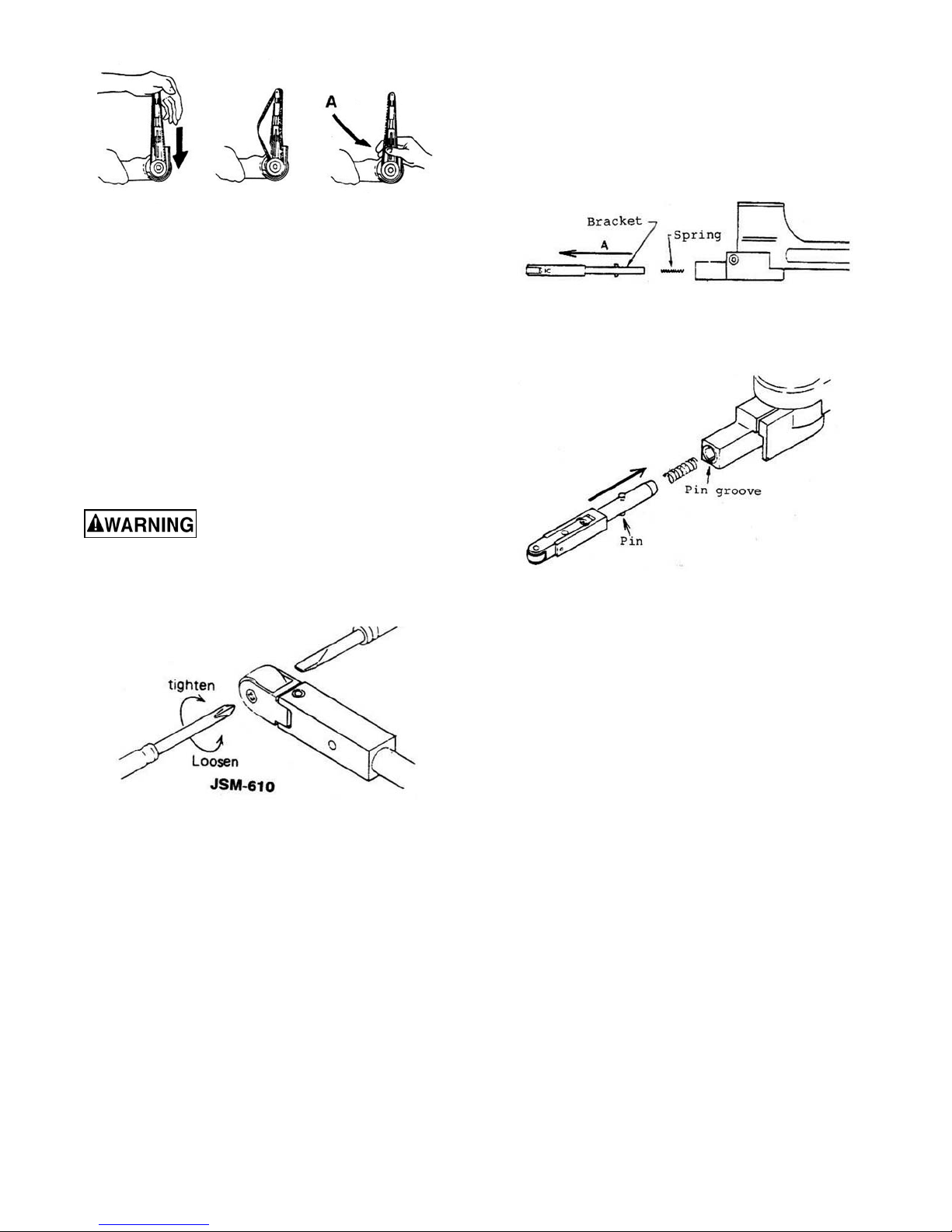
Figure 4
Shoe Replacement
Bracket replacement
1. Disconnect sander from air source.
1. Remove belt.
2. Pull out brac k e t in dir e c t io n la b e le d A , Figure 6. Be
careful not to lose the spring.
The shoe or sanding platen should be replaced w hen,
due to wear, it no longer sits flat but is convex in shape.
1. Disconnect sander from air source.
2. Remove belt (see section titled “Belt
Replacement”).
3. Remove screw(s) and remove old shoe.
4. Install new shoe and fasten with screw(s). Make
sure insert on shoe end engages slot on sander
body.
Idle pulley replacement
Disconnect sander from air hose
before making any repair or adjustment. Failure to
comply may cause serious injury.
Use a screwdriver to remove the screw, then slide out
the shaft and remove the idle pulley. See Figure 5.
Figure 6
3. Insert new bracket b y l ining up pi n wit h pin groo ve.
See Figure 7.
Figure 7
Storage
1. Avoid storing sander in locations with high
humidity.
2. Before storing, apply four to five drops of air tool oil
at the air inlet and run for a brief time to circulate
the oil.
Speed adjustme nt
Figure 5
Replacement parts ar e listed on the following page. To order parts or reach our service department, call 1-800-2746848 Monday through Friday (see our website for business hour s, www.jettools.com). Having the Model Number and
Serial Number of your machi n e avail a ble when yo u call will allow us to serve you quickly and accurat el y.
All models have a brass screw used for belt speed
adjustment found on the underside of the handle. This
has been set at the factory. It is highly recom mended
that the end user not attempt any adjustment to the
speed control.
3
Page 4
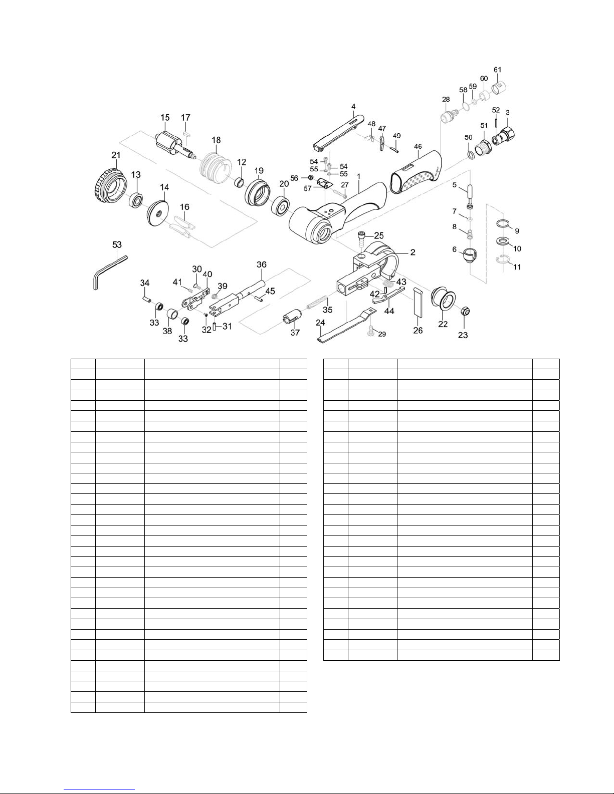
JSM-6100 Mini Belt Sander
Index Part No. Description Qty.
1 61001 Motor Housing 1
2 61002 Guard 1
3 JSM6100-03 Air Inlet 1
4 JSM6100-04 Throttle Lever 1
5 JSM6100-05 Valve Stem 1
6 JSM6100-06 Valve 1
7 JSM3330-44 O-Ring (3.8x1.9) 1
8 JSM6100-08 Spring 1
9 JSM6100-09 O-Ring (14.5x1.5) 1
10 JSM6100-10 Spacer 1
11 JSM6100-11 Retaining Ring (RTW-18) 1
12 61012
13 BB-607ZZ Ball Bearing (607ZZ) 1
14 61014 Rear End Plate 1
15 61015 Rotor 1
16 61016 Rotor Vane 4
17 61017 Key (3x3x10) 1
18 61018 Cylinder 1
19 61019 Front End Plate 1
20 BB-628ZZ Ball Bearing (628ZZ) 1
21 61021 Cap 1
22 61222 Drive Pulley 1
23 TS-1540041 Hex Nut (M6) 1
24 61024 Shoe 1
25 40343 Screw (M5x16) 1
26 61026 Dust Cover 1
27 JSM6100-27 Screw (M4x25) 1
28 JSM6100-28 Muffler 1
29 TS-2284082 Pan Head Screw (M4x8) 1
30 61035 Screw (M3x8) 1
31 61036 Spring Pin 1
32 61037 Screw 1
33 BB-684ZZ Ball Bearing (684ZZ) 2
Spacer 1
Index Part No. Description Qty.
34 61039 Idle Pulley Shaft 1
35 61040 Spring 1
36 61041 Tension Bar 1
37 61042 Bushing 1
38 61043 Idle Pulley 1
39 61044 Spring 1
40 61045 Bracket 1
41 61046 Set Screw (M3x6) 1
42 61048 Spring Pin (2.5x8) 1
43 61049 Spring 1
44 61050 Safety Lever 1
45 JSM6100-45 Lock Pin (3x11.8) 1
46 JSM6100-46 Grip 1
47 JSM6100-47 Safety Bar 1
48 JSM6100-48 Spring 1
49 40337 Spring Pin (3x18L) 1
50 40130 O-Ring (8.8x1.7) 1
51 JSM6100-51 Screw 1
52 JSM6100-52 Pin (2x13.8) 1
53 TS-152705 Hex Wrench (4mm) 1
54 TS-2284082 Pan Head Screw (M4x8) 2
55 TS-2361041 Lock Washer (M4) 2
56 TS-1540021 Nut (M4) 1
57 JSM6100-57 Lever Support 1
58 JSM5130-35 O-Ring (14x1) 1
59 JSM6100-59 O- Ring (5.8x1.9) 1
60 JSM6100-60 Muffler 1
61 JSM6100-61 Exhaust Sleeve 1
RPK-6100 Repair Kit (contains #7,9,11,16,26)
RBK-6100 Rebuild Kit (contains #30-34,38-41)
4
 Loading...