

.JET
EQUIPMENT & TOOLS
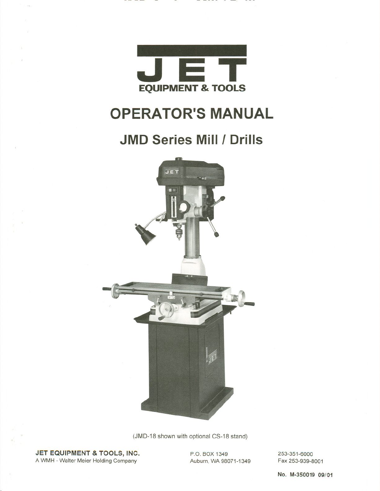
OPERATOR'S MANUAL
JMD Series Mill I Drills
(JMD-18shownwith optional CS-18stand)
JET EQUIPMENT & TOOLS, INC.
A WMH - Walter Meier Holding Company
P.O. BOX 1349
Auburn, WA 98071-1349
253-351-6000
Fax 253-939-8001
No. M.350019 09/'01
Important Information
1-YEAR
LIMITED WARRANTY
JET offers a one-year limited
warranty on this product
REPLACEMENT PARTS
Replacement parts for this tool areavailabledirectlyform JET Equipment&Tools.
To place an order,call 1-800-274-6848. Please have the followinginformationready:
1. Visa, MasterCard, or DiscoverCard number
2. Expirationdate
3. Part number listedwithin thismanual
4. Shipping address otherthan a PostOffice box.
REPLACEMENT PART WARRANTY
JET Equipment & Tools makes every effort to assure that parts meet high quality and durability
standards and warrants to the original retail consumer/purchaser of our parts that each such
part(s) to be free from defects in materialsand workmanshipfor a period of thirty (30) days from
the date of purchase.
PROOF OF PURCHASE
Please retain your dated sales receiptas proofof purchaseto validate the warranty period.
LIMITED TOOL AND EQUIPMENTWARRANTY
JET makes every effort to assure that its products meet high quality and durability standards and warrants
to the original retail consumer/purchaserof our products that each product befree from defects in materials
and workmanship as follows: 1YEAR LIMITED WARRANTYON THISJET PRODUCT. Warranty does not
apply to defects due directly or indirectly to misuse, abuse, negligence or accidents, repairs or alterations
outside our facilities or to a lack of maintenance. JET LIMITS ALL IMPLIED WARRANTIES TO THE
PERIOD SPECIFIED ABOVE FROM THE DATE THE PRODUCT WAS PURCHASED AT RETAIL.
EXCEPT AS STATED HEREIN,ANY IMPLIEDWARRANTIES OR MECHANTABILITYAND FITNESS ARE
EXCLUDED. SOME STATES DO NOT ALLOW LIMITATIONS ON HOW LONG THE IMPLIED
WARRANTY LASTS, SO THE ABOVE LIMITATION MAY NOT APPLY TO YOU. JET SHALL IN NO
EVENT BE LIABLE FOR DEATH, INJURIES TO PERSONS OR PROPERY OR FOR INCIDENTAL,
CONTINGENT, SPECIAL OR CONSEQUENTIAL DAMAGES ARISING FROM THE USE OF OUR
PRODUCTS. SOME STATES DO NOT ALLOW THE EXCLUSION OR LIMITATION OF INCIDENTAL OR
CONSEQUENTIAL DAMAGES, SO THE ABOVE LIMITATION OR EXCLUSION MAY NOT APPLY TO
YOU. To take advantage of this warranty, the product or part must be returned for examination, postage
prepaid, to an authorized service station designated by our Auburn office. Proof of purchase date and an
explanation of the complaint must accompany the merchandise. If our inspection discloses a defect, JET
will either repair or replace the product or refund the purchase price, if we cannot readily and quickly
provide a repair or replacement, if you are willing to accept such refund. JET will return repaired product or
replacement at JET's expense, but if it is determined there is no defect, or that the defect resulted from
causes not within the scope of JET's warranty, then the user must bear the cost of storing and returning the
product. This warranty gives you specific legal rights, and you have other rights, which vary, from state to
state.
JET Equipment &Tools. P.O. Box 1349, Auburn, WA 98071-1349 . (253) 351-6000
~ WARNING
Read and understand the entire contents of
this manual before attempting set-up or
operation of this mill/drill.
.
This machine is designed and intended
for use by properly trained and
experienced personnel only. Ifyou are
not familiar with the proper safe use of
mill/drills, do not use this machine until
proper training and knowledge has been
obtained.
.
Keep guards in place. Safetyguards must
be kept in place and in working order.
.
Remove adjusting keys and wrenches.
Before turning on machine, check to see that
any adjusting wrenches are removed from
the tool.
.
Reduce the risk of unintentional starting.
Make sure switch is in the OFF position
before plugging in the tool.
.
Do not force tools. Always use a tool at
the rate for which itwas designed.
.
Use the right tool. Do not force a tool or
attachment to do a job for which it was not
designed.
.
Maintain tools with care. Keep tools sharp
and clean for best and safest performance.
Follow instructions for lubrication and
changing accessories.
.
Always disconnect the tool from the
power source before adjusting or
servicing.
.
Check for damaged parts. Check for
alignment of moving parts, breakageof
parts, mounting, and any other condition that
may affect the tools operation. A guard or
any part that is damaged should be repaired
or replaced.
.
Turn power off. Never leave a tool
unattended. Do not leave a tool until it
comes to a complete stop.
.
Keep work area clean. Cluttered areas and
benches invite accidents.
.
Do not use in a dangerous environment.
Do not use power tools in damp or wet
locations, or expose them to rain. Keep
work area well lighted.
.
Keep children and visitors away. All
visitors should be kept a safe distance from
the work area.
.
Make the workshop child proof. Use
padlocks, master switches, and remove
starter keys.
.
Wear proper apparel. Loose clothing,
gloves, neckties, rings, bracelets, or other
jewelry may get caught in moving parts.
Non-slip footwear is recommended. Wear
protective hair covering to contain long hair.
Do not wear any type of glove.
.
Always use safety glasses. Every day
glasses only have impact resistant lenses;
they are not safety glasses.
.
Do not overreach. Keep proper footing and
balance at all times.
.
Do not place hands near the cutterhead
while the machine is operating.
.
Do not perform any set-up work while
machine is operating.
.
Read and understand all warnings posted
on the machine.
.
This manual is intended to familiarize you
with the technical aspects of this
mill/drill. It is not, nor was it intended to be,
a training manual.
.
Failure to comply with all of these
warnings may result in serious injury.
Some dust created by power sanding, sawing, grinding, drilling and other construction activities
contains chemicals known to cause cancer, birth defects or other reproductive harm Some
examples of these chemicals are:
. Lead from lead based paint
. crystalline silica from bricks and cement and other masonry products, and
. arsenic and chromium from chemically-treated lumber
Your risk from those exposures varies, depending on how often you do this type of work To reduce
your exposure to these chemicals work in a well ventilated area. and work with approved safety
equipment, such as those dust masks that are specifically designed to filter out microscopic
particles
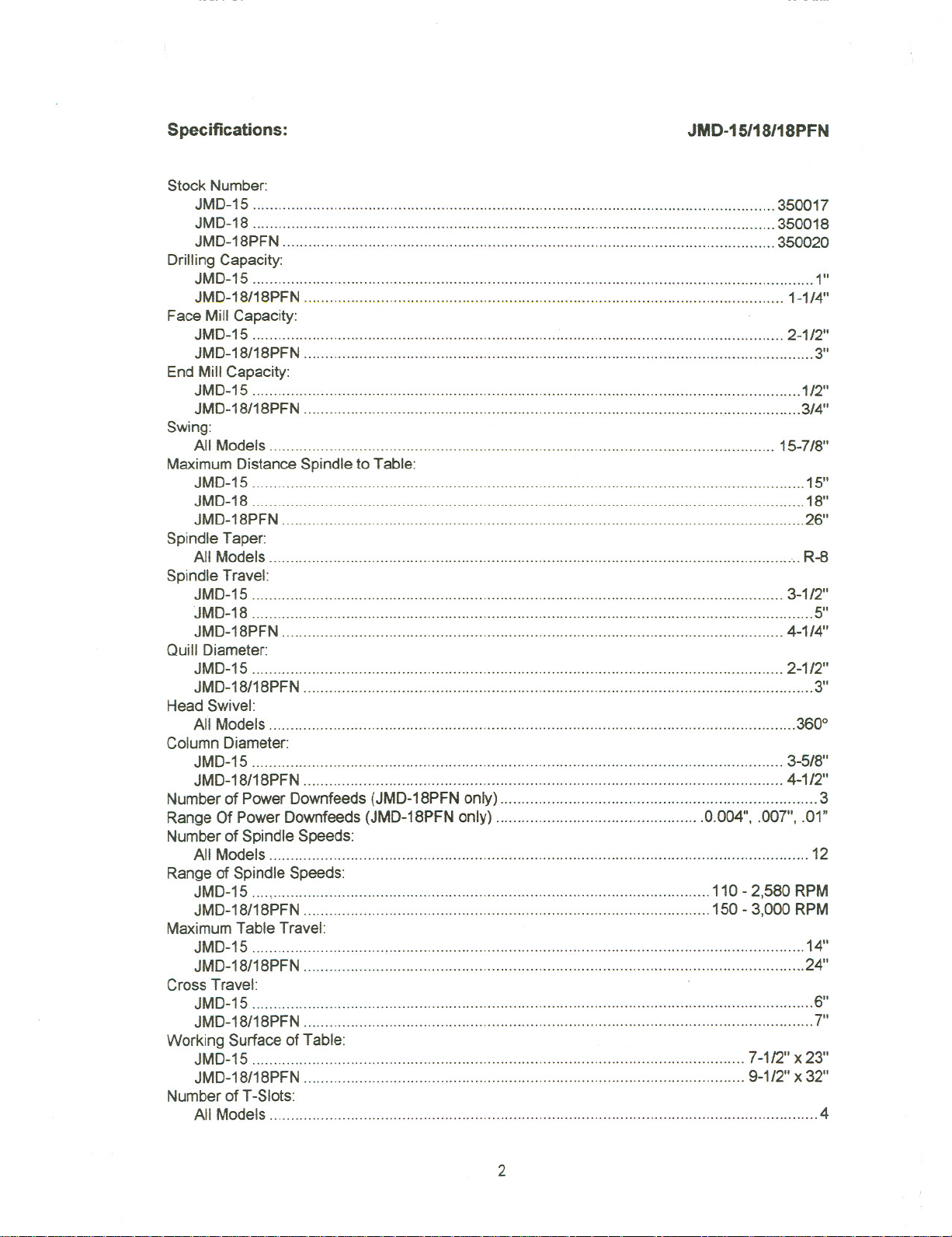
Specifications:
Stock Number:
JMD-15 350017
JMD-18 , 350018
JMD-18PFN 350020
Drilling Capacity:
JMD-15 1"
JMD-18/18PFN 1-1/4"
Face Mill Capacity:
JMD-15 """"""""""""""""""""""""""""""'''''''''''''''''''''''''''''''''''''''''''''''''''''''''''''''' 2-1/2"
JMD-18/18PFN """"""""""""""""""""'"''''''''''''''''''''''''''''''''''''''''''''''''''''''''
End Mill Capacity:
JMD-15 1/2"
JMD-18/18PFN """""""""""'"'''''''''''''''''''''''''''''''''''''''''''''''''''''' """'''''''''''''''''''''''''''''' .3/4"
Swing:
All Models 15-7/8"
Maximum Distance Spindle to Table:
JMD-15 """""""'"'''''''''''''''''''''''''''''''''''''''''''''''''''''''''''''''''''''''''''''''''''''''''''''''''''''''''''''''' 15"
JMD-18 '"'''''''''''''''''''''''''''''''''''''''''''''''''''''''''''''''''''''''''''''''''''''''''''''''''''''''''''''''''''''''' 18"
JMD-18PFN "'''''''''''''''''''''''''''''''''''''''''''''''''''''''''''''''''''''''''''''''''''''''''''''''''''''''''''''''''''''''' 26"
JMD-15/18/18PFN
3"
Spindle Taper:
All Models , .".. R-8
Spindle Travel:
JMD-15 , 3-1/2"
JMD-18 "'"'''''''''''''''''''''''''''''''''''''''''''''''''''''''''''''''''''''''''''''''''''''''''''''''''''''''''''''''''''''''''''''' 5"
JMD-18PFN 4-1/4"
Quill Diameter:
JMD-15 """"""""""""""""""""""'''''''''''''''''''''''''''''' .., 2-1/2"
JMD-18/18PFN , ""'"'''''' " 3"
Head Swivel:
All Models ...360°
Column Diameter:
JMD-15 '''''''''''''''''''' '''''''''''''''''''''''''''''''''' 3-5/8"
JMD-18/18PFN 4-1/2"
Numberof Power Downfeeds(JMD-18PFNonly) 3
Range Of Power Downfeeds (JMD-18PFN only) .0.004", .007", .01"
Numberof Spindle Speeds:
All Models 12
Range of Spindle Speeds:
JMD-15 "","""""""""""""""""""""""'" 110-2,580 RPM
JMD-18/18PFN 150- 3,000 RPM
MaximumTable Travel:
JMD-15 , ...14"
JMD-18/18PFN """""""""'"'''''''''''''''''''''''''''''''''''''''''''''''''''''''''''''''''''''''''''''''''''''''''''''' ..24"
Cross Travel:
JMD-15 , 6"
JMD-18/18PFN . ... , ...7"
Working Surface of Table:
JMD-15 .. ,... 7-112" X23"
JMD-18/18PFN " 9-1/2" X 32"
Number of T-Slots:
All Models 4
2
T-Slot Size:
JMD-15 ..9/16"
JMD-18/18PFN """'''' """"""""""'"'' 5/8"
T-Slot Centers:
JMD-15 ... ""'" ... ... ...... 1-1/2"
JMD-18/18PFN ... ... ...... ...... ... ... ...... 2-1/16"
Overall Dimensions:
JI\,IID-15 ... """'" ... ... ... ... ...~6-1 /2"L x 37-1/2"W x 35-1/2"H
JMD-18 """""""'''''''''''''''''''''''''''''''''''''''''''''''''''''''''''''''''''''''' 42-1/2"L x 39-3/4"W x 43-1/2"H
JMD-18PFN """'"'''''''''''''''''''''''''''''''''''''''''''''''''''''''''''''''''''''' 42-1/2"L x 39-3/4"W x 51-1/2"H
Base Dimensions:
JMD-15 """"""""'''''''''''''''''''''''''''''''''''''''''''''''''''''''''''''''''''''''''' 12-1/2"
JMD-18/18PFN '"'''''''''''''''''''''''''''''''''''''''''''''''''''''''''''''''''''''''''''''''''''' 15-3/4" x23-3/4"
Motor (UL Listed):
JMD-15 ""'''''''''''''''''''''''''''''''''''''''''''''''''''''''''''''''''''''''''''''''''''''''''''''' 1HP, 1Ph, 115V
JMD-18/18PFN 2 HP, 1Ph, 230Vonly
Net Weight (approx.):
JMD-15 .. ... ......... ...... ... ......... ... "'" 440 Lbs.
JMD-18 . """""'''''''''''''' , 660 Lbs.
JMD-18PFN ""'''''''' """'"'''' """'''''''''''''' "'''''''''''' 700Lbs.
Shipping Weight (approx.):
JMD-15 540 Lbs.
JMD-18 """'"'''''''''''''''''' 760 Lbs.
JMD-18PFN """"'" 800 Lbs.
x 19-3/4"
The specifications in this manual are givenas general informationand are not binding. JET
Equipment and Tools reserves the right to effect, at any time and without prior notice, changes or
alterations to parts, fittings, and accessory equipmentdeemednecessary for any reason
whatsoever.
Table of Contents
Warning 1
Specifications 2-3
Table of Contents "" 3
Contents of the Shipping Container 4
Unpacking and Clean-up 4
Assembly 5
Installation 5
Lubrication 6
Electrical Connections 6
Controls 7-8
Operation 9
Arbor Replacement 9
GibAdjustment ""'''''''''''''''''' 10
Power Feed Operation "'"'''''''''' 11
Parts Lists and Breakdowns 12-31
Electrical Schematic 32-33
3
Contents of the Shipping Container
1 Mill/Drill
Accessory Package:
1
Chuck Arbor (installed)
1
1/2" Drill Chuck w/ Chuck Key
1
Adjustable Carbide Facemill
1
Facemill Arbor
2
Bolts, Nuts, and Washers to
Attach Vise to Table
1
2-1/2" Angle Vise (JMD-15)
1
3-1/2" Angle Vise (JMD-18/18PFN)
Handle Rods
3
Plastic Knobs
3
1
3/8"x1" Hex Socket Cap Screw
3/8" Washer
1
1
Crank Body
1
Crank Handle
3mm Hex Wrench
1
5mm Hex Wrench
1
1
23mm Hex Socket Wrench (JMD-18/18PFN)
3
HandWheels w/ Handles
1
Can Touch-Up Paint
1
Operator's Manual
1
Warranty Card
Unpacking and Clean-up
1. Finish removing the crate from the mill/drill.
Unbolt the machine from the crate bottom.
Report shipping damage, if any, to your
distributor.
2. Remove any protective coating with keroseneor
a mild solvent. Do not use gasoline, paint
thinner, or lacquer thinner. These will damage
painted surfaces.
Tools Needed for Assembly
8" Adjustable Wrench or 1/4" to 1-1/4" Combination
Wrench Set
4
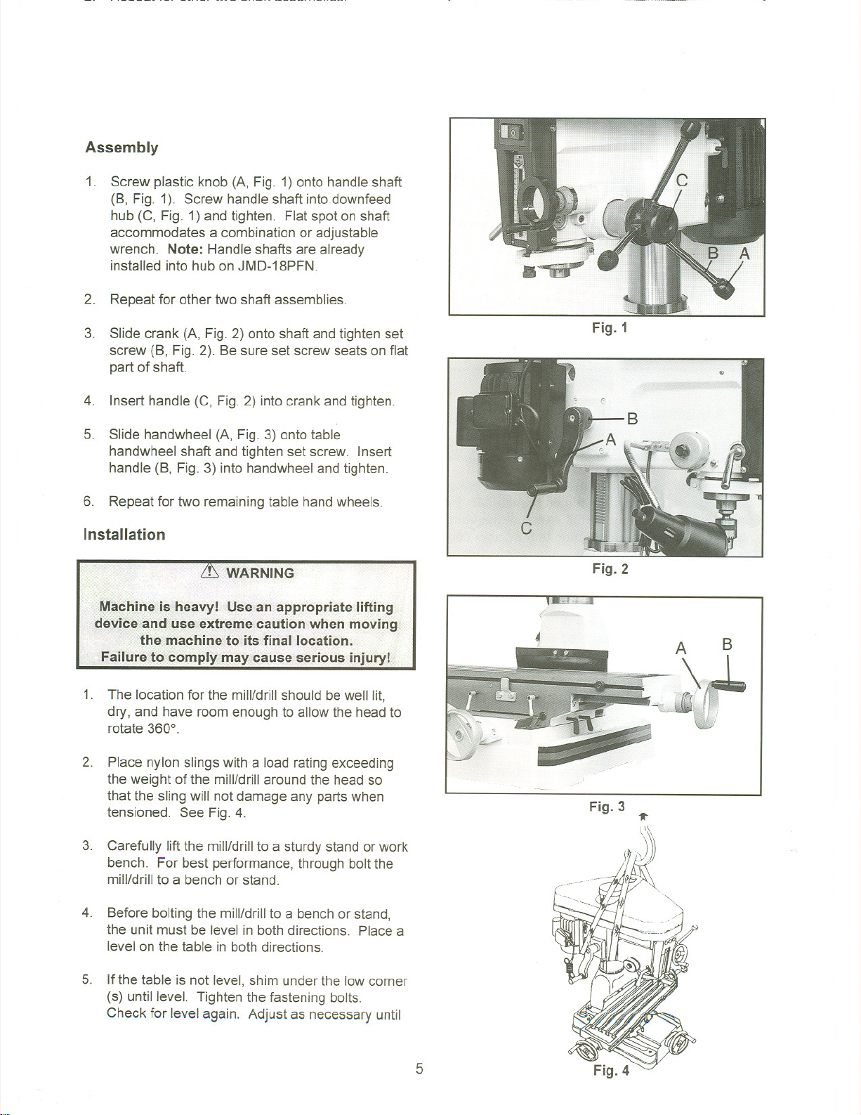
Assembly
1. Screw plastic knob (A, Fig. 1)onto handle shaft
(B, Fig. 1). Screw handle shaft intodownfeed
hub (C, Fig. 1) and tighten. Flatspot on shaft
accommodates a combination or adjustable
wrench. Note: Handle shafts are already
installed into hub on JMD-18PFN.
2. Repeat for other two shaft assemblies.
3. Slide crank (A, Fig. 2) onto shaft andtighten set
screw (B, Fig. 2). Be sure set screw seats on flat
part of shaft.
4. Insert handle (C, Fig. 2) into crank and tighten.
5. Slide handwheel (A, Fig. 3) onto table
handwheel shaft and tighten set screw. Insert
handle (B, Fig. 3) intohandwheel and tighten.
6. Repeat for two remainingtable handwheels.
Installation
1. The location for the mill/drill should be well lit,
dry, and have room enough to allow the headto
rotate 3600.
Fig. 1
Fig. 2
~.
2. Place nylon slings with a load rating exceeding
the weight of the mill/drill around the head so
that the sling will not damage any parts when
tensioned. See Fig.4.
3. Carefully lift the mill/drillto a sturdy stand or work
bench. For best performance, through bolt the
mill/drill to a benchor stand.
4. Before bolting the mill/drillto a bench or stand,
the unit must be level in both directions. Place a
level on the table in both directions.
5. If the table is not level, shim under the low corner
(s) untilleve!. Tighten the fastening bolts.
Check for level again. Adjust as necessary until
Fig. 3 ...
V\
J)
5
the mill/drill is level after the fastening hardware
has been tightened.
Lubrication
Lubricate all ball oilers on the machine once daily
with 20W machine oil.
The spindle bearings are permanentlysealed and
require no lubrication.
Electrical Connections
CURRENT CARRYING PRONGS
w
e
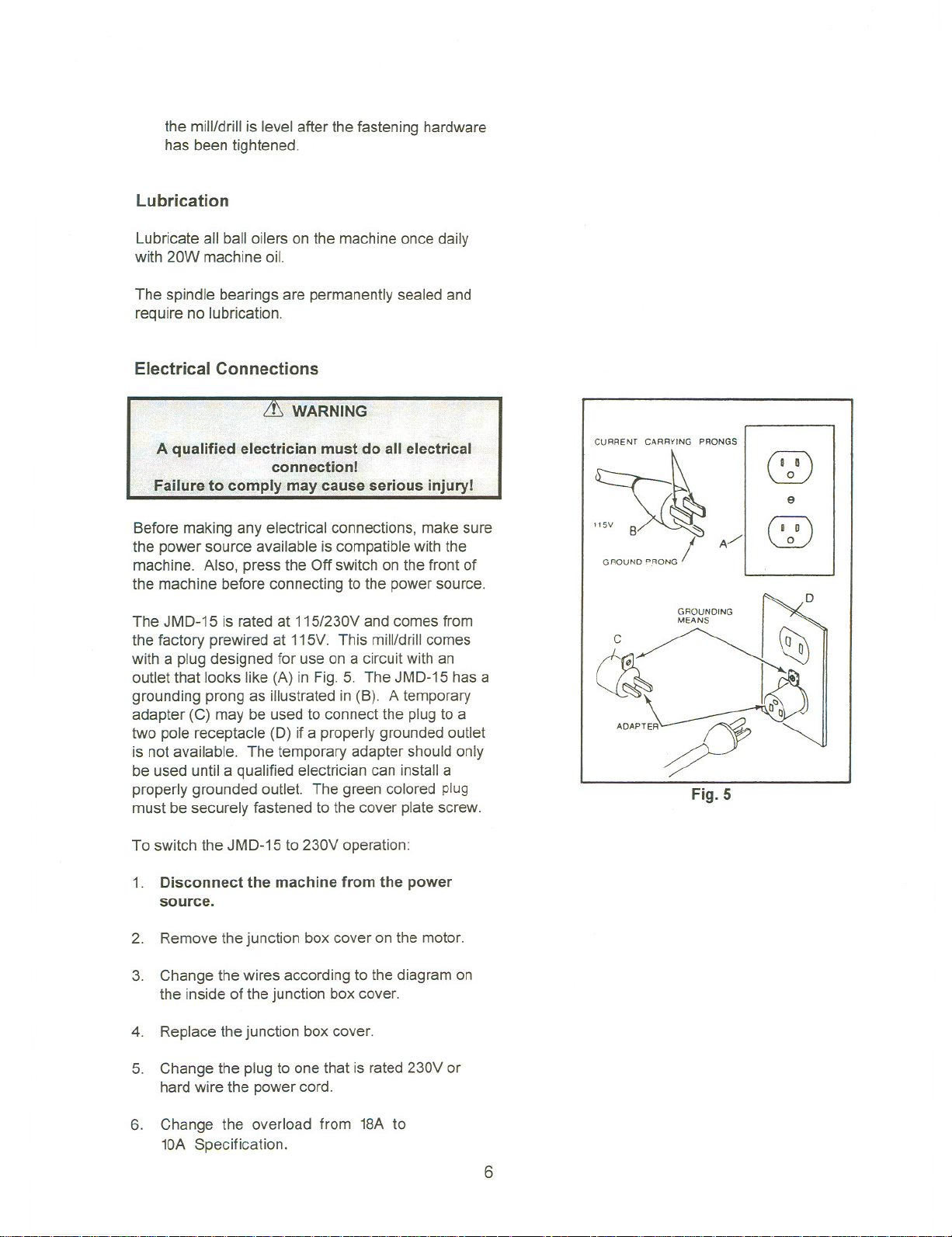
Before making any electrical connections, make sure
the power source available is compatible with the
machine. Also, press the Off switchon the front of
the machine before connecting to the power source.
The JMO-15 is rated at 115/230Vand comes from
the factory prewired at 115V. This mill/drillcomes
with a plug designed for use on a circuitwith an
outlet that looks like (A) in Fig. 5. The JMO-15has a
grounding prong as illustratedin (B). A temporary
adapter (C) may be usedto connect the plugto a
two pole receptacle (0) if a properly grounded outlet
is not available. The temporary adapter should only
be used until a qualified electriciancan install a
properly grounded outlet. The green colored plug
must be securely fastened to the cover platescrew.
To switch the JMO-15 to 230V operation:
1. Disconnectthe machine from the power
source.
2. Removethe junction box cover on the motor.
3. Change the wires according to the diagram on
the inside of the junction box cover.
~
GROUND D.RONG
~~~
,~,,~
I
~ROUNDING
Fig. 5
A/
CZ)
4. Replacethe junction box cover.
5. Change the plugto one that is rated230V or
hardwire the power cord.
6.
Change the overload from 18A to
10A Specification.
6
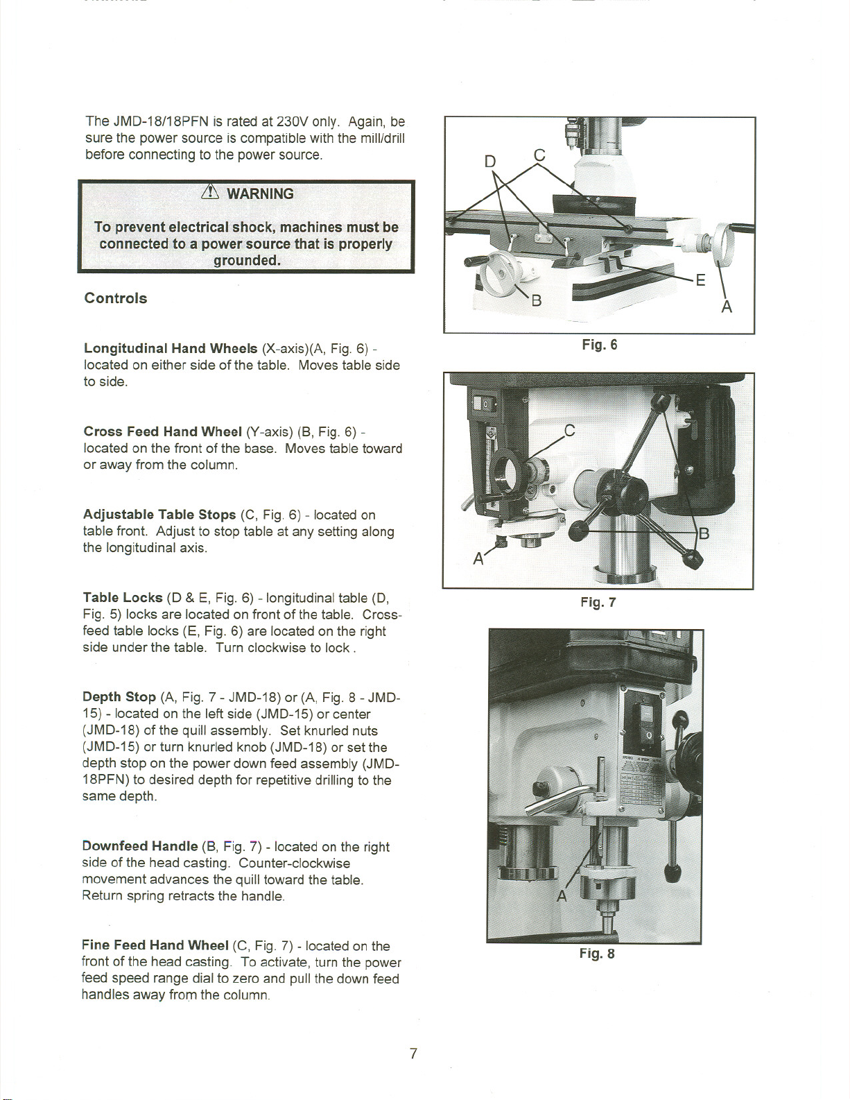
The JMD-18/18PFN is rated at 230V only. Again, be
sure the power source is compatiblewith the mill/drill
before connecting to the power source.
Controls
c
Longitudinal HandWheels (X-axis)(A, Fig. 6) -
located on either side of the table. Movestable side
to side.
Cross Feed Hand Wheel (Y-axis) (8, Fig.6) -
located on the front of the base. Movestable toward
or away from the column.
Adjustable Table Stops (C, Fig.6) - locatedon
table front. Adjust to stop table at any setting along
the longitudinal axis.
Table Locks (D & E, Fig. 6) - longitudinaltable (0,
Fig. 5) locks are located on front of the table. Cross-
feed table locks (E, Fig. 6) are located on the right
side under the table. Turn clockwise to lock.
Depth Stop (A, Fig.7 - JMD-18) or (A, Fig. 8 - JMD-
15) -located on the left side (JMD-15)or center
(JMD-18) of the quill assembly. Set knurlednuts
(JMD-15) or turn knurled knob (JMD-18) or set the
depth stop on the power down feed assembly (JMD-
18PFN)to desired depth for repetitivedrillingtothe
same depth.
Fig. 6
Fig.7
Downfeed Handle (8, Fig. 7) - locatedon the right
side of the head casting. Counter-clockwise
movement advances the quill toward the table.
Return spring retracts the handle.
Fine Feed Hand Wheel (C, Fig. 7) - located on the
front of the head casting. Toactivate,turn the power
feed speed range dial to zero and pull the down feed
handles away from the column.
Fig. 8
7
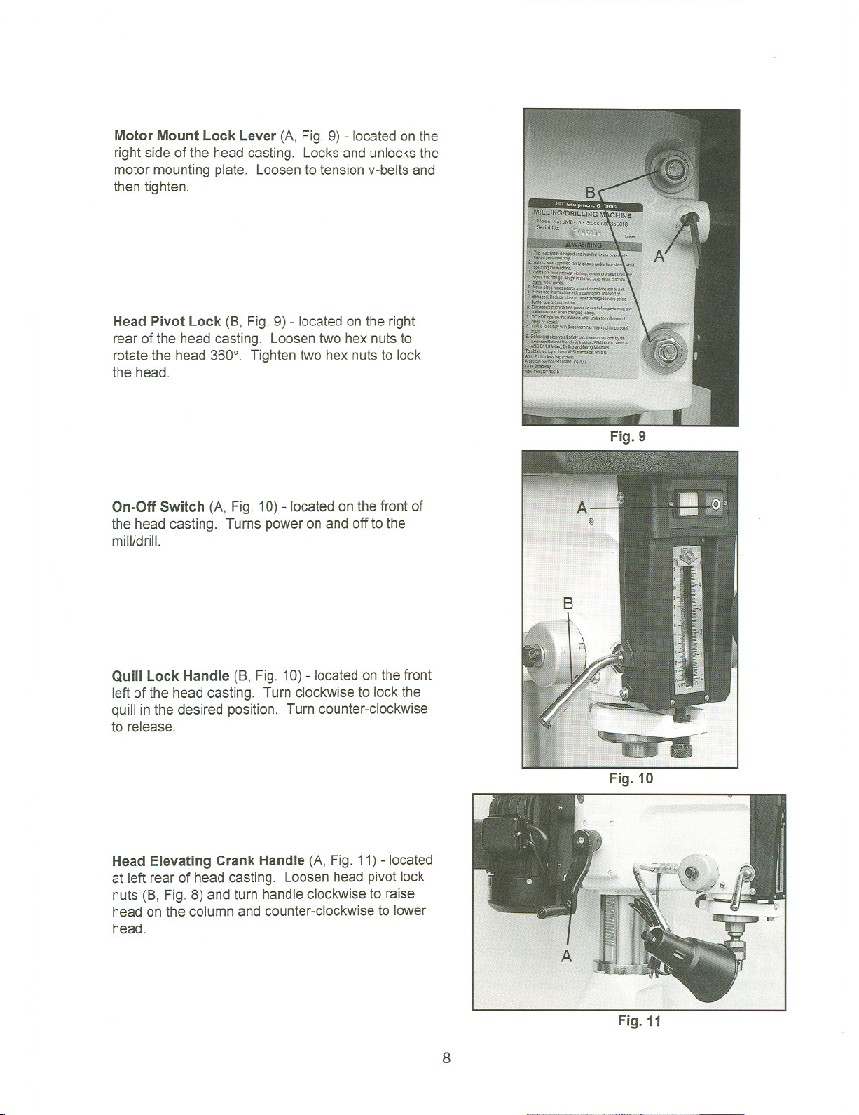
Motor Mount Lock Lever (A, Fig. 9) - located on the
right side of the head casting. Locks and unlocks the
motor mounting plate. Loosen to tension v-belts and
then tighten.
Head Pivot Lock (8, Fig. 9) - locatedon the right
rear of the head casting. Loosen two hex nuts to
rotate the head 360°. Tighten two hex nuts to lock
the head.
On-Off Switch (A, Fig. 10) -located on the front of
the head casting. Turns power on and off to the
mill/drill.
Fig. 9
Quill Lock Handle (8, Fig. 10) - located on the front
left of the head casting. Turn clockwise to lockthe
quill inthe desired position. Turn counter-clockwise
to release.
Head Elevating Crank Handle (A, Fig. 11)- located
at left rear of head casting. Loosenhead pivotlock
nuts (8, Fig. 8) and turn handleclockwise to raise
head on the column and counter-clockwiseto lower
head.
Fig. 10
Fig. 11
8
Operation
Changing Spindle Speeds
1. Disconnect the machine from the power
source.
2. Release two catches on the belt cover and open.
3. Loosen the motor mount lock lever(A, Fig, 9)
and pull the motor toward the head casting to
release tension on the v-belts.
4. Arrange the v-belts on the pulleysfor the desired
speed according to the speed chart on the inside
of the belt cover.
5. Tension the v-belts by pushing the motor away
from the head casting and locking the motor
mount lock lever.
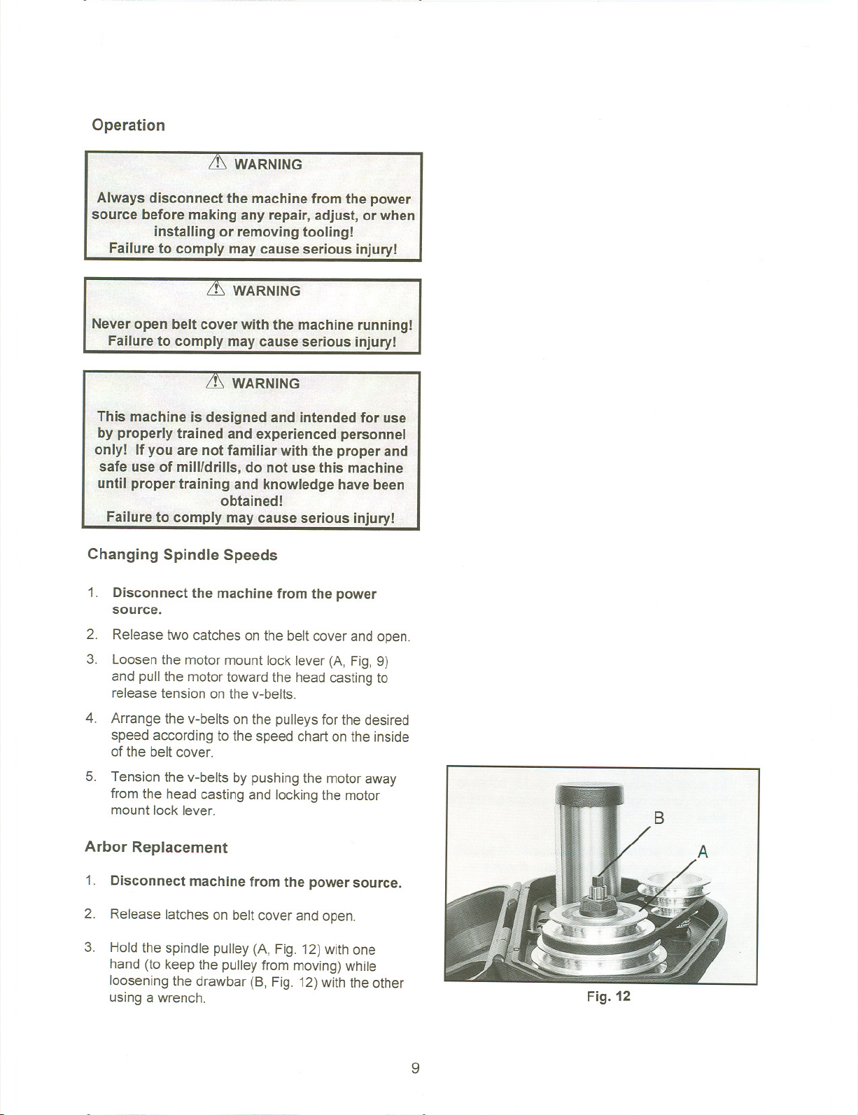
Arbor Replacement
1. Disconnect machine from the power source.
2. Release latches on belt cover and open.
3. Hold the spindle pulley (A, Fig. 12)with one
hand (to keep the pulley from moving)while
loosening the drawbar (8, Fig. 12)with the other
using a wrench.
Fig. 12
9

4. Loosen the drawbar approximatelythree to four
full turns.
5. Tap the drawbar head with a rubbermalletto
dislodge the arbor.
6. Grasp the arbor with one hand while loosening
the draw barwith the other. Continueto loosen
the drawbar untilthe arbor can bewithdrawn
from the spindle.
7. Place the new arbor into the spindle nose.
Thread the drawbar into the arbor and tighten
the drawbar with a wrench while holdingon to
the spindle pulley.
drawbar!
etween pull
Gib Adjustment
After a period of time, movement of the table over
the ways will cause normalwear. To adjust the gibs
for this wear:
1. The horizontal gib adjustmentscrew (A, Fig. 13)
is found to the right on the tableface. The
traverse gib adjustment (8, Fig. 13) screw is
found on the right side of the saddle underthe
table.
2. Turn each screw slightly clockwiseto tighten.
Turn the table handwheels and check the
tension.
3. Re-adjust as required.
Fig. 13
10

Power Feed Operation (JMD-18PFN only)
1. Set the power feed speed range dial (A, Fig. 14)
to the desired rate.
2. Set the depth stop to the desired setting by
lowering the quill to the desired depth and
holding in place. Turn the collar (8, Fig. 14)
counter-clockwise until zero is indicatedand
then tighten the lock handle (C, Fig. 14)
3. Start the mill/drill and pull one of two handles(D,
Fig. 14) away from the column to start the power
downfeed.
4. Once the downfeed has reachedthe depth stop,
the trip will release and the spindle will retract.
5. To stop the feed before the cycle has ended or
to disengage the fine feed (E, Fig. 14),press one
of two handles toward the column.
Note: For best results, all milling operations
should be done with the quill/spindle as close to
the head assembly as possible. Lock spindle
and table in place before starting milling
operations.
Fig. 14
11

......
I\.)
8611
87
57
d
73
70
c..
74
3:
c
I
~
CJ'I
:::I:
CD
Q)
c.
»
III
III
CD
3
c-
o<:
87A
19
20-L.I.
:17
I 21

Parts List for the JMD-15 Mill/Drill
Head Assembly
Index Part
No. No.
Description
Size
Qty.
1 JMD15-001"""""'"'''''''''' Arbor Bolt (drawbar) 1
2 JMD15-002"""""""'"'''''' Spindle Lotk Nut 1
3 JMD15-003 Spindle Pulley 1
5 JMD15-005 Outer Bearing Plate 1
6 JMD15-006 Spindle Taper Sleeve 1
7 BB-6007ZZ... Ball Bearing ...'" """"" 2
8 JMD15-008. Bearing Spacer . 1
9 JMD15-009.. C-Ring 1
10. JMD18-010 , C-Ring ..." "'"'' """'''''''''''''''''''''''''''''''' 1
11 JMD15-011 Head ""'"'''''''' 1
12 ... JMD15-012 Rubber Flange 1
13 JMD15-013 Feed Base 1
14 JMD15-014 Lock Nut """" 2
15 BB-30205 Taper Roller Bearing 1
16 JMD15-016 Rack Sleeve """'"'''' 1
17 JMD15-017 Spindle Shaft """'''''''''''''''''''''''''''''''''''''''''''' 1
18 BB-30206 Taper Roller Bearing 1
19 . .JMD15-019 BearingCap ...1
20 JMD15-020 CuttingArbor """"""""'''''''''''''''''''''''''''''''''' 1
21 JMD15-021 ChuckArbor 1
22 ...JMD18-022 """ Handle """"""""""""""""""""""""" 1
23 JMD15-023 Retainer Ring """""""""" 1
24 JMD15-024 Lock Handle 1
25 JMD15-025 """"'"'''''''''''' Fixed Collar """""'"'''''''''''''''' 1
26 JMD15-026 Fixed Collar Thread f
27 JMD15-027 Screw Key 3/8 1
35 JMD18-035 Bearing Spacer """""'" """"""" ... 1
38 JMD18-038 """""" Lock Bolt wi Knob """"""""""'" 1
39 JMD18-039 Handle Rod '" """""""""""'" ""'" ... ..3
40 JMD18-040 Knob ... ...""""'" 3
42 JMD18-042 Feed Handle WheeL 1
44 JMD18-044 Micro Adjusting Indicator 1
45 ...JMD18-045 ... Worm Cover """'" "" ... ..1
46 BB-62022 Ball Bearing 2
47 JMD18-047 "'"'''''''''''''''''' Worm Shaft 1
51 JMD18-051 Leaf Screw 1
52 JMD15-052 Head Lock Bolt """""""""""'"'''''''''''''''''''''' 1/2x7 2
54 JMD15-054 Graduated Rod and DiaL 1
55 JMD15-055.. Graduated Dial(re:JMD15-054) '"'''''''''''' 1
56 JMD15-056A Switch """""""'''''''''''''''''''' 1
57 JMD15-057 Name Plate 1
58 JMD15-058 Head Handle 1
59. JMD15-059 """""'" """"" Worm Shaft 1
60 JMD15-060 '"'''''''''''''''''''' Worm 1
61 JMD15-061 Shaft 1
62 JMD18-062 Compression Spring 1
13

63 JMD15-063 Pin""""""""""""""""''''''''''''''''''''''''''''''''', 1
66 JMD15-066 """""""" Motor Mount ""'"'''''''' """"" 1
67 ... JMD15-067. Motor "'''''''''''''''''''''''''''''''''' 1
JMD15-067A ""'"'' Capacitor (Not Shown) 1
69 JMD15-069 Belt Cover (ser.#8040225 and lower) 1
JMD15-069P Belt Cover (ser.#8040226and higher) 1
69-1 JMD15-069A Upper Belt Cover Cap (ser.#8040225and lower) 1
JMD15-069P1 Upper Belt Cover Cap (ser.#8040226 and higher) 1
69-2 JMD15-069B Upper Belt Cover Plate (ser.#8040225 and lower 1
JMD15-069P2 Upper Belt Cover Plate (ser.#8040226 and higher) 1
70 JMD15-070 Motor Pulley """" 1
71 VB-A31.., V-B.elt 1
72 BB-62042 Ball Bearing ... .. 2
73 .JMD15-073 Inter Pulley .. 1
74 VB-A38 V-Belt 1
75 JMD15-075 InterPulley Shaft (ser.#8040225 and lower).. 1
JMD15-075P Inter Pulley Shaft (ser.#8040226 and higher). 1
76 JMD15-076 SpeedChange Inter Pulley Base (ser.#8040225 and lower) 1
JMD15-076P SpeedChange Inter Pulley base (ser. #8040226 and higher) 1
79 JMD18-079""""'"'''''''''''' Rubber Collar 1
85 """ ..JMD18-085 ScrewwI Plumb Knob 1
86 . JMD15-086 Cutter . 1
JMD15-086A Cutter Insert (not shown) .. 4
87 .. ..JMD15-087.. Drill Chuck """"""""""'''''''''''''' 1
87A JMD15-087A Chuck Key "'"'' 1
90 JMD15-090 Tap Screw 2
103 JMD18-103 Spring Cover 1
104......JMD18-104 Spring 1
105......JMD18-105... ,... Spring Base """"""""""""""""""'" 1
106 JMD15-106"'"'''''''''''''''''' Pinion Shaft ,.. : 1
107 .JMD18-107... Worm Gear 1
108 .JMD18-108. Feed Cover 1
110 JMD18-110 Spring Base 1
115 JMD18-115 Spring """"""""'''''''''''''''''' 1
122 JMD18-077 Clip Plate """"'''''''''''''''''''''''''''''''''''''''''''''''' 1
131 TS-081B12 Pan Head Screw 1/4x1/2 5
132 TS-068OO21... , Washer 1/4 5
133 JMD18-133 Round Head Screw 1/4x3/8 3
134 TS-005OO91 Hex Head BoiL 1/4x2 1
135 TS-0561011 Hex NuL "'"'''''''''''' 1/4 1
136 TS-0561051 "... Hex NuL... 1/2 2
137 JMD15-137 '"'''''''''''''''''''' lock Washer 1
138 ..JMD15-138 Rivet 2
139 JMD18-139 Round Head Screw 3/16x3/4 3
140 JMD18-140 Spring Pin " 3x12 2
141 1S-0561031 Hex NuL 3/8 3
142 JMD18-142 Key 7x7x20 1
143 1S-0208041 Hex Socket Cap Screw 5/16x3/4 2
144 TS-0680021 Washer "'"'''''''''''''''''''''''''''''''''''''''''''''''''''''' 1/4 1
145 TS-0270021 Set Screw 5/16x5/16 3
146 TS-0267031 Set Screw 1/4x5/16 1
147 JMD18-147 ". RoundHeadScrew 3/16x1/2 2
148 .JMD18-148
150 TS-0561051.. Hex Nut. 1/2 2
"... C-Retainer Ring ..". 1
14

151 TS-0680061 Washer 1/2 2
152 JMD15-152 RoundHeadScrew 1/4x3/8 6
153 TS-0271061 Set
154 TS-0561071 Hex NuL 5/8 2
155 TS-0680031 Washer 5/16 8
156 TS-0051051 Hex HeadBoiL 5/16x1 4
157 TS-0060011 Hex HeadBolt 3/8x1/2 2
158 TS-0561021 Hex NuL 5/16 4
159 JMD18-159 Key 7x7x40 1
160 TS-0051071 Hex HeadBoiL 5/16x1-1/2 2
Screw 3/8x5/8 1
161 TS-0680031 Washer 5/16 : 2
164 JMD15-164 RoundHeadScrew M3x15 2
187 TS-0680011 Washer 1/4 2
188 JMD18-188 Pan HeadScrew 3/16x3/8 1
208 TS-0561031 Hex NuL 3/8 1
15

=
JMD-15 Table, Base, and Column Assembly
Ie
ClIO
16
..

JMD-15 Table, Base, and Column Assembly
1 JMD18-201 Table Hand Wheel 3
1-1 . JMD18-201-1 Bolt 3
1-2 JMD18-201-2 Handle 3
1-3 JMD18-201-3 Nut 3
2 JMD18-202 Dial Clutch 2
2-1 .JMD18-202-1 Graduated Dial ... 2
3 BB-51103 Thrust Bearing ... ... 4
4 JMD15-204 Square Flange 1
4-2 ...JMD18-204-2 Rivet 4
5 JMD15-205 Table Screw 1
6 ...JMD15-206.. ... Base ... .. ... 1
7 .JMD15-207 Gib Strip 1
8 JMD15-208 Column Base """"""'"'''''''''''''''''''''''''''''''''''' 1
9 JMD15-209 Column Flange Ring 1
10 .JMD15-21 0 Rack 1
11 JMD15-211 Column Head 1
12 JMD15-212 Adjustment Screw 2
13 JMD15-213 Leaf Screw 2
13-1 JMD15-213-1 Locking Handle 2
14 ..JMD15-214 Block. ...... 1
15 JMD15-215 Table Base Nut... 1
16 JMD15-216 Center Base 1
17 JMD15-217. Antidust Plate.. ...... ...... 1
19 JMD18-219 Bracket Plate 1
20 .JMD18-220 Table Clutch 1
22 JMD15-222 Left Flange 1
23 JMD18-223 Table Nut 1
24 JMD15-224 Table Screw 1
26 JMD15-226 Right Flange 1
27 JMD15-227 ...... Gib Strip. ... ... ...... ... ... .. 1
28 JMD15-228 Table 1
29 JMD18-229 Block 2
30 JMD18-230 Ring 2
121 JMD15-121 IndicatorPlate 2
143 TS-0207021 Hex Socket Cap Screw 1/4x1/2 2
145 TS-0270021 Set Screw 5/16x5/16 1
166 .JMD18-366 Spring Pin 3
167 JMD18-367... Zero Indicatorw/ Screw 1/4x3/8 2
168 JMD18-368 Oil Ball 5
169 TS-0208041 HexSocketCap Screw 3/8x3/4 8
175 TS-0061071 Hex Head Bolt 7/16x2 4
178 TS-0208111 HexCap Bolt 5/16x2-1/4 1
179 TS-0051011 HexCap Bolt 5/16x1/2 6
180 TS-1502041 Hex Socket Cap Screw , M5x16 2
189 TS-0267041... Set Screw.. ... ... '... 1/4x3/8 3
JMD15-AP Accessory Package (Not Shown) * 1
17

* Contents of the Accessory Package (JMD15-AP):
..JMD15-020 ... ... Cutter Arbor .., """'" '" 1
.. .JMD15-039 .." Handle """"""""""""""""""""""'''''''''''''''' . 3
JMD 15-040 Knob 3
JMD15-087 Drill
.. ...JMD15-086 Cutter '''' """""""""""'"'' """"""'" 1
.365534 Angle Vise "'"'''''''''''''''''''''' """'"'''''''' """"'" ""'"'''''''' ...1
.. ..JMD15-022 Handle , '''''''''''''''''' 4
.JMD15-201 """"""'"'''''''' Wheel """'''''''''''''''''''' 3
.JMD15-058 Handle Crank """'" ""'"'''''''' 1
MP-007 Paint '"'''''''''''''''''''''''''''''''''''''''''''''''''''''''''''' 1
TS-152704 3mm Hex Wrench """""""' ,.1
TS-152705 4mm Hex Wrench '"'''''''''''''''''''''''''''''''''''''''' 1
TS-152706 5mm Hex Wrench 1
.., ..JMD15-381 Washer ... ...1
..JMD15-380 Hex Bolt. """ """ .... ... 1
JMD15-377 Hex Bolt 2
JMD15-378 Hex Nut "'" 2
JMD 15-379 .., Washer 2
MP-007 Touch Up Paint 1
TS-0071 011 Hex Cap BoiL """"'" ""'''' 5/8x1-1/2 3
... TS-0680081 ...""""'"'''''''' Flat Washer .." 5/8 3
. ..TS-0561 071 Hex Nut ... 5/8 ., 3
Chuck 1
18

......
(!)
.86
54
! f:>" 74~
~~33 ",~, 0
23
11 63
.9 62
79 ~'
~
I
c..
!:
C
I
.....
CO
I
-
.....
CO
""D
-n
Z
:r:
(1)
AI
Q,
»
(II
(II
(1)
3
tT
-<
157
,17
132
1j
67

Parts List for the JMD-18/18PFN Mill/Drill
Head Assembly
Index Part
No. No.
1 .JMD18-001 Draw Bar 1
2 JMD18-002 Spindle Lock Nut(S/N 8050816 and lower) 1
JMD18-002A Spindle Lock Nut(S/N 8050817 and higher)... 1
3 JMD18-003 " Spindle Pulley (SIN 9041552 and lower) 1
JMD18-003A Spindle Pulley (SIN 9051553 and higher) 1
5 JMD18-005 " Outer Bearing Plate " 1
6 JMD18-006 '"'''''''''''''''''''' Spindle Taper Sleeve (SIN 8050816 and lower) 1
JMD18-006A Spindle Taper Sleeve (SIN 8050817 and higher) 1
7 BB-6009ZZ , Ball Bearing .., 2
8 .JMD18-008... ".. Bearing Spacer .." .." 1
9 .JMD18-009 , C-Retaining Ring 1
10 .. JMD18-01 O. C-Retaining Ring """""""""" '''''''''''''''''''''''''''''' 1
11 ..JMD18-011 Head Body
JMD18-011A Head Body (SIN 9051553 and higher) 1
12 ...,....JMD18-012 Rubber Flange " 1
13 JMD18-013 Feed Base " 1
14 ...JMD18-014 Lock NuL " """'" "'"'''''' 2
Description
(SIN 9041552 and lower) 1
Size
Qty.
15 BB-30206 Taper Roller Bearing " 1
16 ..JMD18-016 Rack Sleeve "... .." " 1
17 JMD18-017 Spindle Shaft , 1
18 BB-30207 Taper Roller Bearing 1
19... JMD18-019 ..".. Bearing Cap ". 1
20 .JMD18-020 , Cutting Arbor , 1
21 JMD18-021 "",,'"''''''''''''''
22 .JMD18-022 Handle "... " " 1
23 " .JMD18-023.. ..." Retainer Ring ...' 1
24 ..JMD18-024 Lock Handle ""'''' 1
25 JMD18-025 , Fixed Collar " 1
26 JMD18-026 " Fixed Collar (Thread) 1
27 ...JMD18-027 " .., Screw Key ..." 3/8" 1
35 .JMD18-035 ... Bearing Spacer ,. , .,... ,...1
38 JMD18-038 Lock Bolt w/knob 1
39 ..JMD18-039 Handle Rod ..., " ..." ""'"'''''''''''' 3
40 JMD 18-040 , Knob 3
42 ..".. ..JMD18-042 Feed Handle Whee! 1
ChuckArbor 1
44 JMD18-044 MicroAdjustingIndicator , 1
45 JMD18-045 " Worm Cover , 1
46 BB-6202Z Ball Bearing 2
47 JMD18-047 .." Worm Cover " 1
50 JMD 18-050 Lock Handle , 1
51 ..JMD18-051 ..".. Leaf Screw ,.. " ".. ..., 1
52 JMD18-052 Head to Column Lock BoiL 5/8"xS" 2
54... JMD18-054 Graduated Rod 1
55 JMD18-055 Faceplate (S/N:xxx2331 and lower) 1
JMD18-055AN Faceplate (S/N:0062332 and higher) 1
JMD18-PFNc55 Faceplate 1
20

56 JMD18-056 Switch (S/N:205088 and lower) """"''''''''''''''''''''''''''''''''''''''. 1
JMD18-056A Switch (Between S/N:205089 and S/N:xxx2331) 1
JMD18-056AN Switch (S/N:0062332 and higher) 1
57 JMD18-057 Spindle Speed Chart (SIN 9041552 and lower) 1
JMD18-057A Spindle Speed Chart (SIN 9051553 and higher) 1
58.""" .JMD18-058 ... Handle Crank 1
59 . JMD18-059...... Worm Shaft 1
60 .. ..JMD18-060 Wonn 1
61 JMD18-061 Shaft 1
62 JMD18-062 CompressionSpring 1
63 ..JMD18-063 Pin 1
66 JMD18-066 Motor Mount 1
67 .JMD18-067 Motor 1
69 JMD18-069 Poly Belt Cover 1
69-1 JMD18-069-1 Cover Cap 1
69-2 JMD18-069A Upper Belt Cover Section 1
69-3 .JMD18-069-3 Screw. 2
70 JMD18-070 MotorPulley(SIN9041552andlower) '"'''''' 1
JMD18-070A Motor Pulley (SIN 9051553 and higher) 1
71 JMD18-071 VB-B34(SIN 9041552 and lower) 2
JMD18-071A VB-B33 (SIN 9051553 and higher) 1
72 BB-6204Z .." Ball Bearing " 1
73 JMD18-073 Inter Pulley (SIN 9041552 and lower) 1
JMD18-073A Inter Pulley (SIN9051553 and higher) 1
74...m..VB-B41 m...V-Belt(SIN9041552and lower)..., ... ..1
VB-B42 V-Belt (SIN 9051553 and higher) 1
75 JMD18-075 Inter Pulley Shaft 1
76 JMD18-076A Speed Change Inter Pulley Base 1
77 JMD18-077 Clip "'"'''''''''''''''''''''''''''''''''''''''''''''''''''''''''''' 1
79 JMD18-079 Collar """'" ..." """""""""'" 1
85 JMD18-085 Screw w/Plumb Knob ..1
86 JMD18-086 Cutter . ""'"'' 1
.. ..JMD18-086A Cutter Insert (not shown) 4
87 JMD18-087 Drill Chuck 1
JMD18-087A Chl;JckKey (not shown) 1
92 JMD18-092 Set Position Block """'''''''''''''''''''''''''''''''''' 1
93 ..JMD18-093 Lock Nut ...1
94 JMD18-094 SupportBase ... .."" "'" . 1
95 JMD18-095 Knob(w/136 spring pin) ... . ..1
96. JMD18-096 Front Cover Plate... '''''''''''''''''''''''''''''''''''''''' 1
97 JMD18-097 Switch Protection """" ... 1
101 JMD18-101 """"""""""'" Head Raise Bracket ."""'" 1
102 JMD18-102 Limit Plate ..1
103 JMD18-103 Cover(w/104 spring) '"'''''''''''''''''''' '"'''''''' ...1
104 JMD18-104 ""'"'''''''''''''''' Spring ."'" 1
105 ..JMD18-1 05 Spring Base 1
106 JMD18-106 Pinion Shaft 1
107 JMD18-107 Worm Gear ... ......... . ...1
108 .JMD18-1 08 Feed Cover 1
110 JMD18-110 Spring Base """"""'"'''' 1
114 JMD18-114 Bushing "'''' .. .... .1
115 JMD18-115 Spring """""""'" ... 1
131 TS-0051021 Hex Head Bolt 5/16"x5/8" 5
132 TS-0680311 """" Washer ... 5/16" ""'" .12
133 JMD18-133 "'''''''' '"'''''''''' RoundHeadScrew 1/4"x3/8" 3
21

134 TS-0050091 Hex Head BoiL 1/4"x2" 1
135 TS-0561 011 """"""""""" Hex Nut """""""" 114" 1
136 JMD18-136 Spring Pin (re :JMD18-095) 1
137 .JMD18-137 '"'''''''''''''''''''' Lock Washer 1
139 .JMD18-139 """"""""""'" Round Head Screw 3/16"x3/4" 3
140 .JMD18-140 """""'"'''' Spring Pin '"'''''''''''''''''''''''''' ... 2
141 ,.TS-0561 031 , Hex Nut 3/8" 1
142 .. JMD18-142.. """'"'''''' Key "''''''''''''''''''''''''
7x7x20mm 1
143 TS-0208041 Hex Socket Cap Screw 5/16"x3/4" 2
144......TS-0680021 Washer '"'''''''''''''''' 1/4"x1" 1
145 TS-0270021 Set Screw 5/16"x5/16" ...3
146 TS-0267031 Set Screw 1/4"x5/16" 1
147 JMD18-147 Round Head Screw 3/16"x1/2" 2
148. JMD18-148 C-Retainer Ring 1
150 """ TS-0561 071 , Hex Nut """"'''''''''''''''''''''''''' .5/8" 4
151 TS-0680081 ..,...Washer 5/8" 2
152 .JMD18-152 Tap Screw 1/8"x3/8" 4
153 TS-0271061 Set Screw 3/8"x5/8" 1
154 ..JMD18-154... C-Retaining Ring 2
155 1S-0207061 Hex Socket Cap Screw 1/4"x1" 4
156 TS-0051051 '.Hex Head BoiL 5/16"x1" 4
157 TS-0061011 HexHead Bolt 7/16"3/4" 2
158 TS-0561021... Hex Nut " 5/16" 4
159 ..JMD18-159 Key 7x7x37mm 1
160 TS-0051071 Hex Head BoiL 5/16"x1-1/2" 2
161 TS-068oo31 Washer """""""""" 5/16" 2
163 JMD18-163 RoundHead Screw 1/4"x1/2" 4
164 ..JMD18-164 Round Head Screw M3x15 2
184 ..JMD18-184 Round Head Screw 5/32"x1/4"... 1
185 ..JMD18-185 Washer 5/32" 1
187 JMD18-187""""'"'''''''''''' Lock Washer 1/4" 2
188 JMD18-188 PanHead Screw 3/16"x3/8" 1
208 TS-0561031 Hex Nut '"'''''''''''''''''''' 3/8" 1
22

JMD-18/18PFN Table, Base, and Column Assembly
N
0')
....
-
!::
...
;:
5
I
..
23
JMD-18/18PFN Table, Base, and Column Assembly
1 JMD18-201 Table HandWheel 3
1-1 ..JMD18-201-1 Bolt ... 3
1-2 JMD18-201-2 Handle . ...3
1-3 .JMD18-201-3 Nut. ...... 3
2 JMD18-202... Dial Clutch ... 2
2-1 JMD18-202-1 Graduated Ring 2
3 BB-51103 Thrust Bearing 4
4 JMD18-204 SquareFlange 1
4-2 JMD18-204-2 ... ...Rivet ... . 4
5 JMD18-205 Cross Feed Screw 1
6 JMD18-206 Base (wi JMD18-216) 1
7 ..JMD18-207 Gib Strip..... . ...1
8 JMD18-208 Column Base 1
JMD18PF-408 Long Column Base 1
9 JMD18-209 ColumnBase Ring 1
10 JMD18-210... ... Rack ... ... ...1
.. ..JMD18PF-410 ... LongRack... ... 1
11 JMD18-211 ColumnHead 1
12 ...JMD18-212 ...... AdjustmentScrew ... 2
13 JMD18-213 LeafScrew 2
13-1 JMD18-213-1 Locking Handle 2
14 JMD18-214 Block 1
15 .JMD18-215 Cross Feed NuL 1
16 JMD18-216 CenterBase (RE:JMD18-206) 1
17 JMD18-217 Antidust Bracket .."""""""""" 1
19 JMD18-219 PlateBracket 1
20 JMD18-220 Table Clutch 1
22 JMD18-222 Left Flange 1
23 JMD18-223 LongitudinalNut 1
24 JMD18-224 LongitudinalScrew 1
26 JMD18-226 RightFlange 1
27 JMD18-227 Gib Strip 1
28 JMD18-228 Table 1
29 JMD18-229 FixedBlock 2
30 JMD18-230 Ring 2
121 JMD18-121 lndicator Plate 2
131 TS-0051011 Hex Head BoiL 5/16x1/2 6
145 TS-0270021 Set Screw 5/16x5/16 1
156 TS-0208061 Hex Socket Cap Screw 5/16x1 2
166 JMD18-366 Spring Pin 3
167 JMD18-367 Zero Indicatorwi Screw 1
168 JMD18-368 Oil Ball 3/16 5
172 TS-00870071 HexHead BoiL 112x2-112 4
173 TS-0680061 Washer 1/2 4
174 TS-1502041 Hex Socket Cap Screw M5x16 2
175 TS-0051101 Hex Head BoiL 5/16x2-1/4 1
176 TS-0207011 Hex Socket Cap Screw 1/4x1/2 2
182 TS-0208041 Hex Socket Cap Screw 5/16x3/4 6
189 TS-0267041 Set Screw 1/4x3/8 3
JMD18-AP Accessory Package(Not Shown) * 1
24

* Contents of the Accessory Package:
. ...JMD18-020 Cutter Arbor 1
.JMD18-022 Handle .., 4
.JMD18-039 Handle Rod 3
..JMD18-040 Knob 3
.JMD18-050 Lock Handle. 1
.561704 Drill Chuck 1
. ..JMD18-086 Cutter 1
JMD18-021 Chuck Arbor 1
365534 Angle Vise 1
..JMD18-058... Handle Crank 1
JMD18-201 Wheel 3
TS-152704 Hex Wrench 3mm 1
TS-152705 Hex Wrench 4mm 1
TS-152706 Hex Wrench 5mm 1
TS-0209051 Hex Socket Cap Screw 3/8x1 1
TS-0680041 FlatWasher 3/8 1
25

48
Qc..
Q.s::
(1)0
~.=...
-co
CD"
(I)."
CDZ
ia'"
-0
~~
CDCD
0...
I\,)
Q')
""'"
-CD
UlCD
UlQ.
N:.
men
=cn
Q.CD
r-3
i~
CD'<
...
333

Parts List for the JMD-18PFNPower Feed Assembly
Old Style Serial # 9041552 and Lower
Index Part
No. No.
248 .290111 RF " "'" Main Pulley.. ' , 1
Description
Size
Qty.
249 JMD18PFN-249 Set Screw 1/4x3/8 2
250 JMD18PFN-250 Flat Head Screw 3/16x3/8 1
... ...291 001. GearBox ... ...... 1
251
252 291006 Worm Shaft ... ..1
253 290110... ..., ... Sub-Pulley. ... 1
254 ..,... JMD18PFN-254 Key 5x5x35 1
255 . JMD18PFN-255 C-Ring : 1
256 BB-6oo3ZZ , Ball Bearing 2
257 ..291 004 Worm Base "'.." 1
258 JMD18PFN-258 Hex Socket Cap Screw M6x20 3
259 JMD18PFN-259.. LockWasher M6 3
260 291003 ClutchBlock
" "'"'''''''''' 1
261 JMD18PFN-261 Set Screw M6x6 2
262 JMD18PFN-262 Key 5x5x10 1
263 291002 Worm
..'" " 1
264 2450054 " '" Spring ..'" 1
265 . 291005. AdjustableRing 1
266 JMD18PFN-266 Set Screw M6x6 2
267 .2450014 Cover " '..".. "'.."""' 2
268 2450007 WormGear Shaft 1
269 JMD18PFN-269 Key 5x5x25 1
270 291007 Transmission Gear 1
271 JMD18PFN-271 SetScrew M6x6 2
272 ..2450012 ". Pinion Gear. "" "'"'' ".. """"" 1
273 2450011 PinionGear 1
274 2450010 PinionGear
""""'"'''''''''''''''''''''''''''''''' 1
275 2450013 FixedRing"''''''''''''''''''''' , 1
276 JMD18PFN-276 Set Screw """"""'"'''''''''''''''''''''''''''''''''''''''' 2
277 CA6202LLB """""""""'''' Ball Bearing .' 4
278 . 2450009 Speed Change Lever 1
279... ...291 008 Stopper 1
280 JMD18PFN-280 Hex Socket Cap Screw M5x12 2
281 JMD18PFN-281 Cover """'''''''''''''''''''''''''''''''''''''''''''''''''''''''' 1
282 JMD18PFN-282 ".. C-Ring ' , 4
283.. JMD18PFN-283 """"" C-Ring '"'' """'''''''''''''''''''''''''''''''''''''''''' 1
284 2450044 m PinionGear m "'"'' . . 1
285 2450043.. " , PinionGear '"'''''''''''''''''''''''''''''''''''''''''''' .. 1
286 .2450042 Pinion Gear 1
287 JMD18PFN-287.. Key '''''''''''''''''''''''''''''''''''''''''''''''''''''''''''''' 5x5x30 1
288 ......291 012 """""""'" ".." Transmission Worm 1
290 291015 Graduated Bottom Plate 1
291 JMD18PFN-288 HexSocket Cap Screw M6x12 2
292 291014.. Micro Adjusting Indicator 1
293 JMD18PFN-293 Set Screw M6x6 1
294".".6142-2""""""."."..."" Wheel." " 1
27

295 ... ...JMD18PFN-295 Nut "'"'''''''''' ... M8 """'''''' 1
296... ...JMD18PFN-296 Handle """""""""'"'''''''''''''''''''' ... .. """"""" ... ..., ..1
297 JMD18PFN-297 Handle Bar Screw 1
301 ..291009 Gear Shaft ..... ."""""" 1
302 ..2450019 Speed DiaT""""""""""""""''''''''''''''''''''''"" 1
303 JMD18PFN-303 Round Head Screw M4x25 1
304 JMD18PFN-304 Speed Scale ,. 1
305 .2450016 Position Screw """"""""'''''''''''''''''''''''' . 1
307 JMD18PFN-307 "'''''''''''''' Steel Ball 1
308 .2450060 Pointer """"""""'''''''''''''''''' """'''''''''''''''''''''''''''' 2
309 JMD 18PFN-309 Rivet """ """" '''''''''''''''''''''''''''''''''' .""" 4
310 2450020 Release Block 1
311 2450051 Pin""""'''''''''''''''''''''''''''''''''''''''''''''''''''''''''' 1
312 291010 Pinion Shaft ""'''''''''''''''''''''''''''''''''''''''''''''''' 1
313 .2450022 Key 2
314 ..291011 ... "'"'''' Transmission Gear 1
315 ..2450024 "''''''''' ,.. Clutch Gear Case """'"'''''''''''''''''''''''''''''''''' """'''''''''''''''''''''''''''' 1
316 ".., 2450025 Clutch Key Pin """'"'''''''''''''''' .. 2
317 . .2450027 Spring Pin """'" 2
318
319 .2450026 Clutch Key """"'''''''''''''''''''''''''''''' "'"'''''''''''''''''''''''''' ...2
320 JMD18PFN-320 CoRing 1
321 2450048 Worm Gear Cover """"""""'''''''''''''''''''''''''' 1
322 JMD18PFN-322 '''''.w''''m Round Head SCreW"H'_H.m._m M4x25 3
323 2450029 ClutchBushing '"'''''''''''''''''''''''''''''''''''''''''''' 1
324 .2450030 Bushing Pin '''''''''''''''''''''''''''''''''' 1
325 ..2450031 Bushing Stop ""'"'''''''''''''''''''''' '''''''''''''''''''''''''''''' 1
326 .JMD18PFN-326 Pin '''''''''''''''''''''' 1
327 2450032A , Scale Base 1
328 '.2450033 Scale Base Set Screw '"'''''''' -. 1
329 2450063 Graduated Base Handle 1
330 ..2450037 Handle Body """"""""'''' , -.. ""'''''''''''''''''''' 1
331 .2450038 Handle Rod.. """""""'" "'" ...2
332 .290086 -""",,"""""""'" Knob -"'"'''''''' .. 2
333 2450039 , Pin '"'''''''''''''''''''''''''''''''''''' "'"'''''''''''''''''' -'''''''''' 2
334 2450040 Washer '''''''''''''''''''''''''''''''''''''''''''''' " 1
335 TS-1504031 Hex Socket Cap Screw M8x16 1
336 "'" JMD18PFN-336 Hex Socket Cap Screw M10x85 3
338 .290114 Round Belt... ""'" 1
340 TS-0267041 ". Set Screw ''''''''''''''''''''''' , 1/4x3/8 1
2450028 ""'"'''''''''''''''''''' Spring 2
291001-CP "-""""''''''..".. Gear Box Assembly Complete 1
28

248~
~249
,
'~7
282
z
~i
cnc
~~
-01:)
CD."
cn."
~Z
-. ."
N
to
.>
315
316~/3_20
276
~
381
371
370
~ ~ ,~ 308
368
~ /'/ ---"'"
- // 376-
~ /'/ 377
,/ 294378
!2.0
~~
<DCD
e...
<II."
-CD
<IICD
<IIQ.
W»
1»(1)
=(1)
Q.CD
:1:3
-. 0-
ce-
='-<
CD
...

Parts List for the JMD-18PFN Power Feed Assembly
New Style Serial # 9051553 and Higher
Index Part
No. No.
248
.. 290111 Main Pulley 1
249 ..JMD18PFN-249 Set Screw ""'" """" ..."""""" 1/4"x3/8" 2
250 JMD18PFN-250 Flat Head Screw 3/16"x3/8" 1
Description Size
Qty.
253 .290110 ; Sub-Pulley "'''''''''''''''''''' ""'"'''''' 1
255 JM'D18PFN-255 C-Ring S7 1
256 BB-600322 """"""""""'" Ball Bearing 2
259 JMD18PFN-259 Lock Washer 1/4" 3
261 JMD18PFN-261 Set Screw : M6x6 2
262 JMD18PFN-262 Key 5x5x10 1
264 ......2450054 Spring 1
267 ..2450014 Cover '"'''''''''''''''''' '"'''''''''' . 2
269 JMD18PFN-269 Key 5x5x25 1
276 JMD18PFN-276 Set Screw M6x6 2
282 ..JMD18PFN-282 C-Ring '''''''''''''''''''''''''''''''''' R25 4
294 6142-2 Wheel 1
303 JMD18PFN-303 Round Head Screw M4x25 1
308 2450060 Pointer.. 2
309... ...JMD18PFN-309 Rivet 4
310. 2450020.. Release Block ""'" 1
311 2450051 Pin ""'''''''''''''''''' """"'''''''''''''''' 1
313.. 2450022 Key """"""" 2
315 2450024 Clutch Gear Case ""''''''''''''''''''''''''''''''',,,,,,,, 1
316 2450025 Clutch Key Pin 2
317 2450027 Spring Pin.. 2
318 2450028 Spring ""'"'''''''''''''''''''''''''''''' . 2
319... ...2450026. Clutch Key ',""'"'''''' 2
320 JMD18PFN-320' C-Ring """""""""""""""""""""""""''''""" S25 1
321 2450048 WormGearCover'''''''''''''''''''''''''''''''''''''''''' 1
324 2450030 Bushing Pin '''''''''''''''''''''''''''''''''''''''''''''''''''' 1
325 2450031 Bushing Stop 1
326 JMD18PFN-326 Pin : 1
328 2450033 Scale Base Set Screw 1
329 2450063 Graduated Base Handle 1
330 2450037 Handle Body 1
332 ..290086... """""'''' Knob '"'''''''''''''' 2
333 ..2450039 Pin. '"'' 2
334 2450040 "'''''' '"'''' Washer '"'''''''''''''''''''''' M8 1
335 TS-1504031 """"""""'''''' Hex Socket Cap Screw M8x16 1
338 .290114 Round Belt... 1
340 TS-0267041 Set Screw , 1/4"x3/8" 1
291001-CP Gear Box Assembly Complete (SIN 9041552 and lowerL 1
291001-CPN Gear Box Assembly Complete (SIN 9051553 and higher) 1
342"'" .291 022A.. ,.""'" ... Gear Box '" ,. .. """""""""""'" ..1
343 .291 029A Pinion Shaft 1
344 .2450023 Worm Gear """"""""""""""""" 1
345 291027A Gear Shaft ., 1
346 JMD18PFN-346 , Flat Cross Head Screw M4x4 3
347 291030A Clutch Bushing ""'"'''''''''''''''''''''''''''''''''''''''' 1
30

348 .2450032A Scale Base 1
349 2450038 Knob wi Shaft 2
350 JMD18PFN-350 Hex Socket Cap Screw 5/16"x3-112" 3
351 ..290089 Spring 1
352 JMD18PFN-352 Steel Ball 1
353 .2450079 Speed Lever " 1
354 JMD18PFN-354 Speed Scale , ...1
355 ., CA6003ZZ Bearing ., . 1
356 .245OO82A " Change Gear Lever """""""'''''''' ... 1
357 2450084B TorsionalSpring " 1
358 ..JMD18PFN-358 Key 5x5x32 1
359 2450083A Stop '"'''' ..1
360 "'" .JMD18PFN-360 Pin 2
361 .2450089A Fixed Bushing 1
362 .2450072A ... Gear 1
363 .245007 4A """""""""""'" Bushing 4
364 ..2450071 A Gear 1
365 .2450070A .., Gear 1
366 .291026A , ... Shaft '"'''''''''''''''''''''''''''''''''''''''''''''''''''''''''''' 1
367 .291047 Worm Gear 1
368 ..291028A ,... Transmission Worm ,1
369 JMD18PFN-369 C-Retainer Ring 1
370 2450075A Gear '''''''''''''''''''''''''''''''''' 1
371 .2450076A Gear 1
372 ......2450077 A Gear 1
373 JMD18PFN-373 C-Ring 1
374 .6145 Worm Cover 1
375 ..291051A Micro Adjusting Indicator .. 1
376 ..JMD18PFN-376 Hex Socket Cap Screw 3/16"x3/8" 2
377 ..JMD18PFN-377 Set Screw , .." 1/4"x5/16" 1
378 .JMD18PFN-378.. """'''''''' Set Screw... 5/16"x5/16" 1
379 291032A ... , Base ...1
380 .291049. Bearing Spacer 1
381 H07070 Hex Socket Cap Screw 5/16"x3/4" 1
382 .2450057 Bushing 1
383 .2450098 , T-Screw 5/16"x3/4" 1
384 ,H02050 Hex Nut """"""""""""""""""" ..,... 5/16" 1
385 ..JMD18PFN-385 Hex Socket Cap Screw 1I4"x3/4" 1
386 ..291046 "'"'' Worm Shaft 1
387 ..291050 Clutch Block """"""'"'''''''''''''''''''''''''''' 1
388 .291023A..., Transmission Shaft 1
389 JMD18PFN-389 Key 5x5x45 1
390 .291024A Worm Base 1
31

Electrical Schematic - JMD-15 (115V)
~
(J
START
<{
.J
WilD
l-
I
~
RED
WI;E
l-
I
~
JMD-15 (230V)
CAPAaT~
::.
~
(J
START
<{
RED
STOP
::.
32

Electrical Schematic - JMD-18/18PFN (230V)
BLACK
~
u
START
«
::!Iffi
I
~
RED
33

 Loading...