


Operating Instructions and Parts Manual
Benchtop Cold Saw
Model J-F225
JET
427 New Sanford Road
LaVergne, Tennessee 37086 Part No. M-414220
Ph.: 800-274-6848 Revision C 01/2016
www.jettools.com Copyright © 2016 JET

Warranty and Service
JET® warrants every product it sells against manufacturers’ defects. If one of our tools needs service or repair, please
contact Technical Service by calling 1-800-274-6846, 8AM to 5PM CST, Monday through Friday.
Warranty Period
The general warranty lasts for the time period specified in the literature included with your product or on the official
JET branded website.
• JET products carry a limited warranty which varies in duration based upon the product. (See chart below)
• Accessories carry a limited warranty of one year from the date of receipt.
• Consumable items are defined as expendable parts or accessories expected to become inoperable within a
reasonable amount of use and are covered by a 90 day limited warranty against manufacturer’s defects.
Who is Covered
This warranty covers only the initial purchaser of the product from the date of delivery.
What is Covered
This warranty covers any defects in workmanship or materials subject to the limitations stated below. This warranty
does not cover failures due directly or indirectly to misuse, abuse, negligence or accidents, normal wear-and-tear,
improper repair, alterations or lack of maintenance. JET woodworking machinery is designed to be used with Wood.
Use of these machines in the processing of metal, plastics, or other materials outside recommended guidelines may
void the warranty. The exceptions are acrylics and other natural items that are made specifically for wood turning.
Warranty Limitations
Woodworking products with a Five Year Warranty that are used for commercial or industrial purposes default to a
Two Year Warranty. Please contact Technical Service at 1-800-274-6846 for further clarification.
How to Get Technical Support
Please contact Technical Service by calling 1-800-274-6846. Please note that you will be asked to provide proof
of initial purchase when calling. If a product requires further inspection, the Technical Service representative will
explain and assist with any additional action needed. JET has Authorized Service Centers located throughout the
United States. For the name of an Authorized Service Center in your area call 1-800-274-6846 or use the Service
Center Locator on the JET website.
More Information
JET is constantly adding new products. For complete, up-to-date product information, check with your local distributor
or visit the JET website.
How State Law Applies
This warranty gives you specific legal rights, subject to applicable state law.
Limitations on This Warranty
JET LIMITS ALL IMPLIED WARRANTIES TO THE PERIOD OF THE LIMITED WARRANTY FOR EACH PRODUCT.
EXCEPT AS STATED HEREIN, ANY IMPLIED WARRANTIES OF MERCHANTABILITY AND FITNESS FOR A
PARTICULAR PURPOSE ARE EXCLUDED. SOME STATES DO NOT ALLOW LIMITATIONS ON HOW LONG AN
IMPLIED WARRANTY LASTS, SO THE ABOVE LIMITATION MAY NOT APPLY TO YOU.
JET SHALL IN NO EVENT BE LIABLE FOR DEATH, INJURIES TO PERSONS OR PROPERTY, OR FOR
INCIDENTAL, CONTINGENT, SPECIAL, OR CONSEQUENTIAL DAMAGES ARISING FROM THE USE OF OUR
PRODUCTS. SOME STATES DO NOT ALLOW THE EXCLUSION OR LIMITATION OF INCIDENTAL OR
CONSEQUENTIAL DAMAGES, SO THE ABOVE LIMITATION OR EXCLUSION MAY NOT APPLY TO YOU.
JET sells through distributors only. The specifications listed in JET printed materials and on official JET website are
given as general information and are not binding. JET reserves the right to effect at any time, without prior notice,
those alterations to parts, fittings, and accessory equipment which they may deem necessary for any reason
whatsoever. JET
Product Listing with Warranty Period
90 Days – Parts; Consumable items
1 Year – Motors; Machine Accessories
2 Year – Metalworking Machinery; Electric Hoists, Electric Hoist Accessories; Woodworking Machinery used
for industrial or commercial purposes
5 Year – Woodworking Machinery
Limited Lifetime – JET Parallel clamps; VOLT Series Electric Hoists; Manual Hoists; Manual Hoist
Accessories; Shop Tools; Warehouse & Dock products; Hand Tools; Air Tools
NOTE: JET is a division of JPW Industries, Inc. References in this document to JET also apply to JPW Industries,
Inc., or any of its successors in interest to the JET brand.
®
branded products are not sold in Canada by JPW Industries, Inc.
2

Table of Contents
Warranty and Service .................................................................................................................................... 2
Table of Contents .......................................................................................................................................... 3
Warnings ....................................................................................................................................................... 4
Introduction.................................................................................................................................................... 6
Specifications ................................................................................................................................................ 6
Features ........................................................................................................................................................ 7
Unpacking ..................................................................................................................................................... 8
Assembly ....................................................................................................................................................... 8
Electrical ........................................................................................................................................................ 9
Adjustments ................................................................................................................................................ 10
Controls ....................................................................................................................................................... 12
Operation..................................................................................................................................................... 12
Maintenance ................................................................................................................................................ 13
Lubrication ................................................................................................................................................... 13
Blade Selection ........................................................................................................................................... 14
Troubleshooting Blade and Cutting Problems ............................................................................................ 15
Parts List – J-F225 Cold Saw...................................................................................................................... 16
Exploded View – J-F225 Cold Saw ............................................................................................................. 18
Wiring Diagram ........................................................................................................................................... 19
Ordering Replacement Parts....................................................................................................................... 20
3

Warnings
1. Read and understand the entire owner's manual before attempting assembly or operation.
2. Read and understand the war nings p osted on the m achine an d in t his m anua l. F ailure t o com pl y with
all of these warnings may cause serious injury.
3. Replace the warning labels if they become obscured or removed.
4. The cold saw is des ign ed and intended for us e by properly trained a nd ex per ienc e d p er s onne l on l y. If
you are not familiar with the proper a nd safe operati on of a cold s aw, do not use until proper traini ng
and knowledge have been obtained.
5. Do not use this cold saw for other than its intended use. If used for other purposes, JET disclaims any
real or implied warranty and holds itself harmless from any injury that may result from that use.
6. Always wear approved s afety glasses/face shields while usin g this cold saw. Everyday eyeglass es
only have impact resistant lenses; they are not safety glasses.
7. Before operating the cold saw, rem ove tie, rings, watc hes and oth er je welry, a nd roll s leeves up past
the elbows. Remove al l loo se clothi ng and c onfin e lon g hair. N on-sl ip foot wear or anti-sk id f loor str ips
are recommended. Do not wear glo ves.
8. Wear ear protectors (plugs or muffs) during extended periods of operation.
9. Some dust created by power sanding, sawing, grinding, drilling and other construction activities
contain chemicals k nown to cause cancer , birth defects or other reproductiv e harm. Some ex amples
of these chemicals are:
• Lead from lead based paint.
• Crystalline silica from bricks, cement and other masonry products.
• Arsenic and chromium from chemically treated lumber.
Your risk of exposure varies, depending on how often you do this type of work. To reduce your
exposure to these chemicals, work in a well-ventilated area and work with approved safety
equipment, such as face or dust masks that are specifically designed to filter out microscopic
particles.
10. Do not operate this machine while tired or under the influence of drugs, alcohol or any medication.
11. Make certain the switch is in the OFF position before connecting the machine to the power supply.
12. Make certain the machine is properly grounded.
13. Make all machine adjustments or maintenance with the machine unplugged from the power source.
14. Remove adjusting keys and wrenches. Form a habit of checking to see that keys and adjusting
wrenches are removed from the machine before turning it on.
15. Keep safety guards in place at all times when the machine is in use. If rem oved for maintenance
purposes, use extreme caution and replace the guards immediately.
16. Make sure the cold saw is firmly placed on a secure foundation.
17. Check damaged parts. Before further use of the machine, a guard or other part that is damaged
should be carefully checked to determine that it will operate properly and perform its intended
function. Check f or alignment of m oving parts, bindin g of moving parts , breakage of parts, m ounting
and any other conditions that may affect its oper ation. A guard or other part th at is damaged shoul d
be properly repaired or replaced.
18. Provide for adequate space surrounding work area and non-glare, overhead lighting.
19. Keep the floor around the machine clean and free of scrap material, oil and grease.
20. Keep visitors a safe distance from the work area. Keep children away.
4

21. Make your workshop child proof with padlocks, master switches or by removing starter keys.
22. Give your work undivided a ttention. Look ing around, c arrying o n a conversati on and “hors e-pla y” are
careless acts that can result in serious injury.
23. Mainta in a balanced stance at all times so that you do not fall into th e bl ade or oth er m oving par ts. Do
not overreach or use excessive force to perform any machine operation.
24. Use the r ight to ol at the c orr ect spee d and feed rate. Do n ot for ce a t ool or att achm ent to d o a j ob f or
which it was not designed. The right tool will do the job better and safer.
25. Use recommended accessories; improper accessories may be hazardous.
26. Maintain tools with care. Keep saw blades sharp and clean for the best and safest performance.
Follow instructions for lubricating and changing accessories.
27. T ur n of f the machine before clea n ing. Us e a br ush or compres sed air to remove c hips or d ebr is — do
not use your hands.
28. Do not stand on the machine. Serious injury could occur if the machine tips over.
29. Never leave the machine running unattended. Turn the power off and do not leave the machine until it
comes to a complete stop.
30. Remove loose items and unnecessary work pieces from the area before starting the machine.
Familiarize yourself with the following safety notices used in this manual:
This means that if precautions are not heeded, it may result in minor injury and/or
possible machine damage.
This means that if precautions are not he eded, it m ay result in serious inj ury or p ossibly
even death.
5

Introduction
The JET Model J-F225 Cold Saw is a pendulum bench saw designed for cutting metals. Operation is
manual: after turning on the electrical power supply to the machine and clamping the workpiece in the
vice, the operator starts the blade by pressing the micro switch located on the control lever; he then
moves the head downwards in order to cut the material; after completing the cut, the cutting head returns
to position ready for a new cutting cycle. The Model J-F225 can perform miter cuts up to 45° to the left.
Specifications
Model Number ...................................................................................................................................... J-F225
Stock Number ..................................................................................................................................... 414220
Disc Blade
Disc diameter ......................................................................................................................... 225mm (9 in.)
Hole diameter (in) .................................................................................................................................... 1.3
Blade thickness (in) ............................................................................................................................... 0.08
Cutting Speed
Blade Speed (RPM) ................................................................................................................................. 50
Vise Opening (Max) ...................................................................................................................................... 6
Motor ..................................................................................................................... 1HP, 1PH, 115VAC, 60Hz
Other
Coolant Capacity .......................................................................................................................... 2.7 quarts
Dimensions ...................................................................................................................25"L x 15"W x 28"H
Weight .................................................................................................................................................84 lbs
Cutting Capacity
Degree Round Square (vise slot clamp) Rectangle
90°
45°
The specificatio ns in this m anual ar e given as general inform ation and are not binding. JET res erves the
right to effect, at an y tim e and without pr ior not ice, c ha nges or altera tions to parts, f ittings, and ac cess ory
equipment deemed necessary for any reason whatsoever.
Ø 2-1/2”
Ø 2”
2-1/4”(W) x 2-1/4”(H) 2-1/2”(W) x 2-15/16”(H)
1-5/8”(W) x 1-5/8”(H) 1-3/4”(W) x 1-1/4”(H)
6

Features
In this section, refer to Figure 1 except where
otherwise specified.
Miter Cutting Head
The miter cutting head (F igure 1) is t he unit that
cuts the material and consists of a cast iron
base, blade support unit and guard,
transmission unit, and m otor. T he depth of cut is
set by adjusting the depth cut stop. The miter
cutting head swivels and can be adjusted from
0–45º.
Miter Positioning
The cutting angle (miter position) is manually
adjusted and described in Performing Angle
Cuts on page 10.
Self-centering Vise
The self-centering vise holds the work piece in
place during cuttin g. The work piece is secured
in the vise by turning the vise handle.
Trigger Handle
The trigger handle is located on the operating
lever used to raise and lower the saw. It
contains a micro-switch (Figure 9), which starts
the saw when pressed.
Figure 1
Flood Coolant System
Coolant is dispensed directed onto the saw
blade from a coolant fitting on the upper blade
guard. Coolant is provided through tubing from
the coolant pump mounted on the back of the
motor casing.
The coolant flow control valve (Figure 2) is
located on the back of the saw. Adjust the valve
to achieve desired flow. Flow starts when the
switch on the machine is turned on and the
micro-switch in the trigger handle is depressed .
Releasing the micro-switch stops coolant flow.
This coolant system can operate with either a
soluble oil base coolant or water-soluble
synthetic coolant. Coolant should be changed
regularly. Some r ecomm ended brands are DoAll
and Lenox. These coolants are ava ilable at your
local industrial distributor.
Figure 2
7

Unpacking
Remove packing and two wrapped parcels
containing the handle and workstop, requiring
simple assem bly, from shipping cont ainer. T hen lift
machine from c ontainer and place on sturdy work
surface.
Assembly
Handgrip
Tools requ ired
23mm wrench
Crosspoint screwdriver
Referring to Figure 3:
1. Screw the threaded end (D) of the operating
handle into the threaded opening (E) of the
crank case. Back off slightly, aligning the
position of the trigger handle (A) for a
comfortable grip when operator stands before
the machine.
2. Secure the operating handle (B) by tightening
the lock nut (C) with a 23mm wrench.
3. Attach the connector (F) of the cable to the
socket (G) on the side of the switchbox.
4. Attach the cable cover (H) to the crankcase (K). Secure the cover with four M4x6 pan
head screws (J).
Tighten with a crosspoint screwdriver. Make
sure the cable can move freely inside the
cover and is not pinched between the cover
base and crankcase.
Figure 3
Work Stop
Tools requ ired
adjustable wrench
Referring to Figure 4, assemble the workstop as
follows:
1. Loosen the lock knob (A) on the stock stop (B)
and slide it onto the stop bar (C).
2. Thread the assembly (D) into the mounting
bracket (E). Place an adj ustable wrenc h at the
indents (F) and tighten the rod.
8
Figure 4
Electrical
Electrical Requirements
When connecting the cold saw to the power
source outlet, the outlet must be properly
grounded to protec t the operator from electr ical
shock.
In the event of a malfunction or breakdown,
grounding provides a path of least res istance f or
electrical current to reduce the risk of electrical
shock. This m achine is eq uipp ed wit h an elec tric
cord having an equipment-groundin g conductoroutlet that is properly insta lled and grounded in
accordance with all local codes and ordinances.
This saw is equipped with a power cord.
Improper connection of the equipment groundin g
conductor can result in a risk of electric shock.
The conductor with insulation having an outer
surface that is green (with or without yellow
stripes) is the equipm ent -grounding conductor.
If repair or replacement of the electric cord or
plug is necessary, do not connect the
equipment-grounding conductor to a live
terminal.
Plug power cord into a 110-120V properly
grounded outlet protected by a 14-am p fuse or
circuit breaker.
Do not touch the prongs of
the power cord plug when plugging or
unplugging to or from an outlet.
If improperly grounded, this
power tool can cause serious injury from
electrical shock, particularly when used in
damp locations or near plumbing. If an
electrical shock occur s, there is t he potenti al
of a secondary hazard such as your hands
coming in contact involuntarily with the
rotating blade.
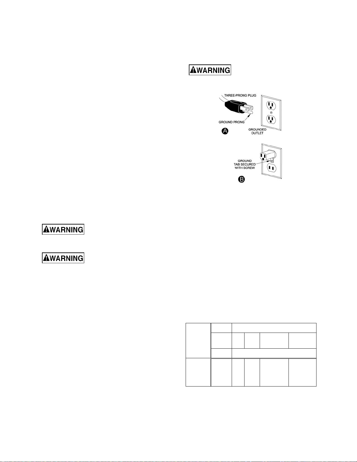
Electrical Connections
The J-F225 Cold S aw is rated at 115V, 1Phase
and is designed for use on a circuit with an
outlet that looks the one shown in Fig. A. and
have a grounding pro ng, also s hown in Fig. A . A
temporary adapter (Fig. B) may be used to
connect the plug to a two-prong receptacle
(Fig. B) if a properly grounded outlet is not
available. A temporary adapter should only be
used until a properly grounded outlet can be
installed by a q ualified elec trician. This ad apter
is not applicable in Canada. The green colored
lug must be fastened to the cover plate screw.
Important: The adapter illus trated i n F i g. B is f or
use only if you already have a properly
grounded two-prong receptacle. Do not modify
the plug provided-if it wil l not fit the outlet, have
the proper outlet installed by a qualified
electrician. Check with a qualified electrician or
service personnel if the grounding instructions
are not completel y understood, or if in doubt as
to whether the tool is properly grounded.
Before plugging into the
power source, be sure that power switch is
in the OFF position.
Extension Cords
Use only three-wire extension cords that have
three-prong grounding type plugs and threeprong receptacles that accept the tool's plug.
Replace or repair damaged or worn core
immediately.
USE PROPER EXTENSIO N CORD. Make sure
your extension cord is good condition. When
using an extension cord, be sure to use one
heavy enough to carr y the current your produc t
will draw. An unders ized cord will cause a dr op
in line voltage resulting in loss of power and
overheating. Table 1 shows the correct size to
use depending on cord length and nameplate
ampere rating. If in doubt, use the next heavier
gage, The smaller the gage num ber, the he avier
the cord.
Volts Total length of cord in feet
Amp
Rating
0 – 06
6 – 10
10 – 12
12 – 16
9
120V
240V
25
50
50
100
AWG
18
16
18
16
14
16
16
12
100
200
16
14
14
not rcmd
Table 1
150
300
14
12
12
not rcmd

Adjustments
Remove power when making
any adjustments. Failure to
comply may result in serious injury!
Performing Angle Cuts
The JET J-F225 c an perform cuts at angles up to
45º to the left. Adjust the angle of a cut as follo ws
while referring to Figure 5:
1. Loosen two hex cap screws (A) with a 6mm
hex wrench to free the turntable.
2. Turn the machine body to any positi on be t ween
0–45º, reading position on the angle scale on
the base.
3. Tighten the hex cap screws (A).
Blade Travel Adjustment
Tools requ ired
12mm wrench
13mm wrench
The height of retract and depth of c ut stop adjustments lim it the upper and lower tra vel limits of the
saw blade.
To make adjustments (refer to Figure 5):
Height of retract – this is the upper travel limit of the
saw blade when the trigger handle is raised.
Adjustment is made by setting the position of
screw B.
Depth of cut stop – this is the lower travel limit of
the saw blade when the trigger handle is brought
down. Adjustment is made by setting the position of
screw C (not visible in photo).
Figure 5
Blade Guard Adjustment
Remove power when making
any adjustments. Failure to
comply may result in serious injury!
Referring to Figure 5:
When the saw head is lowered all the way, the
blade should not be visible (G). If the blade is
visible, the blade guar d (F) needs to be adjusted as
follows:
1. Loosen two socket head cap screws (D) just
enough to permit the bracket (E) movement for
adjustment.
2. Manually adjust the blade guard (H) until blade
is not visible at G.
Note: Durint step 2, the saw must be in the
lowered postion.
3. Tighten the two socket head cap screws (D).
10
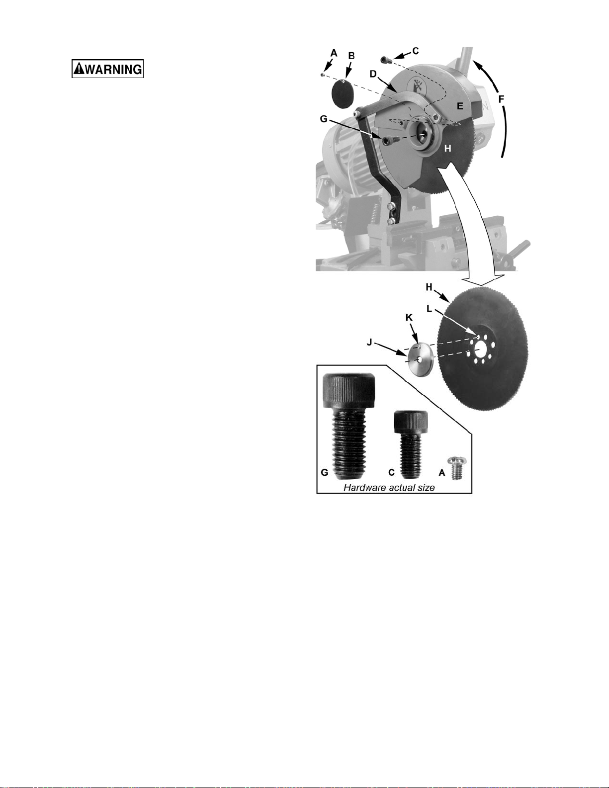
Changing the Saw Blade
The cold saw must not be
connected to the p ower source wh en changing
saw blades. Failure to comply may result in
serious injury!
Remove the saw blade as foll ows while ref erring to
Figure 6:
1. Remove the scr ew (A) and cover plate ( B), or
loosen the screw just enough to sl ide the co ver
plate away to reveal the hub.
2. Remove the socket head cap screw C that
secures the bracket (D) to the lower blade
guard (E).
3. Raise the lower blade guard (E) upwards (F).
4. Remove socket head cap screw (G) that
secures the blade (H).
Note: This screw has a left thread requiring a
clockwise turn to loosen and a counterclockwise turn to tighten.
5. Remove the blade (H) and outer flange (J).
Discard the old blade (or have it resharpened)
and replace with a new one.
6. Install the new blade in the reverse order
described above. Not e that the f lange (J) has a
pin (K) that needs to match up with the correct
keyhole (L), if the blade has more than one
keyhole, make the selection such that the
mounting holes of the flange and blade are
centered.
Figure 6
11
Controls
Power Switch – The power switch has two
positions, off and on. To operate the m achine, the
Power switch must be set to on. Then depress
micro-switch (Figure 8) in the trigger handle to
start.
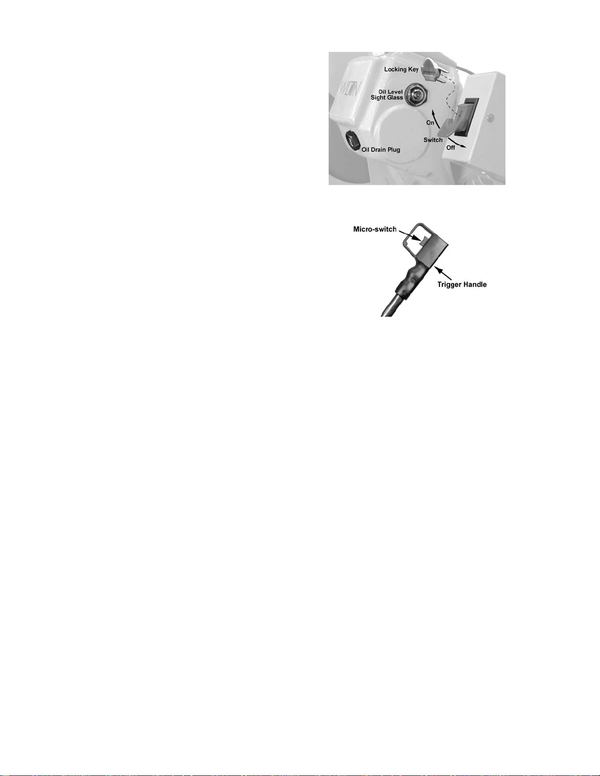
Locking Key – When the saw is not in use, the
switch should b e locked in the off position. T o lock
the switch in the off position, pull out the safety key
(Figure 7). The saw will not start with the key
removed. However, if the ke y is remove d while the
switch is in the on position, it can be turned off
once. The saw will not restart until the key has
been reinserted into the switch.
Trigger Handle – To operate, the On/Off switch
must be set to on and the microswitch on the
trigger handle (Figure 8) depressed.
Figure 7
Figure 8
Operation
Before using the machine:
1. Check that safety devices (ex., blade guards)
are in position and work perfectly and that
personal safety requirements are complied
with.
2. Check the sharpness of the blade and verify
coolant flow.
To operate:
3. Mak e sure the work piece is securely clam ped
in the vise.
4. Turn the power on (Figure 7).
5. Grip the trigger handle ( Fig ure 8) on th e contro l
lever.
6. Start the blade by pressing the micro-switch on
the handgrip.
The down stroke speed of the head is controlled
manually by the operator.
When the cut is complete:
7. Raise the head.
8. Remove the work piece from the vise usin g the
vise hand wheels.
12
 Loading...