

Page 1

This .pdf document is bookmarked
Operating Instructions and Parts Manual
10" Job Site Table Saw
Benchtop Series – Model No. JBTS-10MJS
For models with serial no. 12120886 and higher
JET
427 New Sanford Road
LaVergne, Tennessee 37086 Part No. M-707000
Ph.: 800-274-6848 Revision B
www.j
ettools.com Copyright © 2017 JET
2 01/2017
Page 2

Warranty and Service
JET warrants every product it sells against manufacturers’ defects. If one of our tools needs service or repair, please contact
Technical Service by calling 1-800-274-6846, 8AM to 5PM CST, Monday through Friday.
Warranty Period
The general warranty lasts for the time period specified in the literature included with your product or on the official JET
branded website.
• JET products carry a limited warranty which varies in duration based upon the product. (See chart below)
• Accessories carry a limited warranty of one year from the date of receipt.
• Consumable items are defined as expendable parts or accessories expected to become inoperable within a
reasonable amount of use and are covered by a 90 day limited warranty against manufacturer’s defects.
Who is Covered
This warranty covers only the initial purchaser of the product from the date of delivery.
What is Covered
This warranty covers any defects in workmanship or materials subject to the limitations stated below. This warranty does not
cover failures due directly or indirectly to misuse, abuse, negligence or accidents, normal wear-and-tear, improper repair,
alterations or lack of maintenance. JET woodworking machinery is designed to be used with Wood. Use of these machines in
the processing of metal, plastics, or other materials outside recommended guidelines may void the warranty. The exceptions
are acrylics and other natural items that are made specifically for wood turning.
Warranty Limitations
Woodworking products with a Five Year Warranty that are used for commercial or industrial purposes default to a Two Year
Warranty. Please contact Technical Service at 1-800-274-6846 for further clarification.
How to Get Technical Support
Please contact Technical Service by calling 1-800-274-6846. Please note that you will be asked to provide proof of initial
purchase when calling. If a product requires further inspection, the Technical Service representative will explain and assist
with any additional action needed. JET has Authorized Service Centers located throughout the United States. For the name of
an Authorized Service Center in your area call 1-800-274-6846 or use the Service Center Locator on the JET website.
More Information
JET is constantly adding new products. For complete, up-to-date product information, check with your local distributor or visit
the JET website.
How State Law Applies
This warranty gives you specific legal rights, subject to applicable state law.
Limitations on This Warranty
JET LIMITS ALL IMPLIED WARRANTIES TO THE PERIOD OF THE LIMITED WARRANTY FOR EACH PRODUCT.
EXCEPT AS STATED HEREIN, ANY IMPLIED WARRANTIES OF MERCHANTABILITY AND FITNESS FOR A PARTICULAR
PURPOSE ARE EXCLUDED. SOME STATES DO NOT ALLOW LIMITATIONS ON HOW LONG AN IMPLIED WARRANTY
LASTS, SO THE ABOVE LIMITATION MAY NOT APPLY TO YOU.
JET SHALL IN NO EVENT BE LIABLE FOR DEATH, INJURIES TO PERSONS OR PROPERTY, OR FOR INCIDENTAL,
CONTINGENT, SPECIAL, OR CONSEQUENTIAL DAMAGES ARISING FROM THE USE OF OUR PRODUCTS. SOME
STATES DO NOT ALLOW THE EXCLUSION OR LIMITATION OF INCIDENTAL OR CONSEQUENTIAL DAMAGES, SO THE
ABOVE LIMITATION OR EXCLUSION MAY NOT APPLY TO YOU.
JET sells through distributors only. The specifications listed in JET printed materials and on official JET website are given as
general information and are not binding. JET reserves the right to effect at any time, without prior notice, those alterations to
parts, fittings, and accessory equipment which they may deem necessary for any reason whatsoever. JET
are not sold in Canada by JPW Industries, Inc.
Product Listing with Warranty Period
90 Days – Parts; Consumable items
1 Year – Motors; Machine Accessories
2 Year – Metalworking Machinery; Electric Hoists, Electric Hoist Accessories; Woodworking Machinery used
for industrial or commercial purposes
5 Year – Woodworking Machinery
Limited Lifetime – JET Parallel clamps; VOLT Series Electric Hoists; Manual Hoists; Manual Hoist
Accessories; Shop Tools; Warehouse & Dock products; Hand Tools; Air Tools
NOTE: JET is a division of JPW Industries, Inc. References in this document to JET also apply to JPW Industries, Inc., or any
of its successors in interest to the JET brand.
®
branded products
2
Page 3

Table of Contents
Warranty and Service .......................................................................................................................................... 2
Table of Contents ................................................................................................................................................ 3
Warnings .............................................................................................................................................................. 4
Table Saw Safety ................................................................................................................................................. 6
Specifications ....................................................................................................................................................... 7
Definitions and Terminology ................................................................................................................................ 7
Electrical .............................................................................................................................................................. 8
Grounding Instructions ..................................................................................................................................... 8
115 Volt Operation Only ................................................................................................................................... 8
Extension Cords ............................................................................................................................................... 8
Features ............................................................................................................................................................... 9
Shipping Contents ............................................................................................................................................. 10
Assembly ........................................................................................................................................................... 12
Stand .............................................................................................................................................................. 12
Attaching Saw to Stand .................................................................................................................................. 12
Mounting the Saw to Work Surface ............................................................................................................... 13
Rear Table Extension .................................................................................................................................... 13
Handwheel Handle ......................................................................................................................................... 14
Installing the Blade ......................................................................................................................................... 14
Removing the Blade ....................................................................................................................................... 14
Blade Guard Assembly .................................................................................................................................. 15
Installing the Push-stick Storage .................................................................................................................... 16
Storage ........................................................................................................................................................... 16
Adjustments ....................................................................................................................................................... 17
Setting up the Stand ...................................................................................................................................... 17
Folding the Stand ........................................................................................................................................... 17
Adjusting the Table Insert .............................................................................................................................. 17
Aligning the Blade Guard Splitter ................................................................................................................... 18
90° and 45° Positive Stop Adjustm ent ........................................................................................................... 19
Blade Tilt Pointer ............................................................................................................................................ 19
Blade Parallel to the Miter Slot ....................................................................................................................... 20
Adjusting the Miter Gauge ............................................................................................................................. 21
Rip Fence Adjustment .................................................................................................................................... 21
Rip Fence Indicator ........................................................................................................................................ 22
Table Extension Sc a le Poin ter ....................................................................................................................... 22
Rear Table Extension Adjustment ................................................................................................................. 22
Adjusting the Locking Lever ........................................................................................................................... 22
Additional Blade Adjustments ........................................................................................................................ 20
Operation ........................................................................................................................................................... 23
Basic Saw Operations .................................................................................................................................... 23
Cutting Operations ......................................................................................................................................... 24
Maintenance ...................................................................................................................................................... 28
Push Stick Construction .................................................................................................................................... 29
Troubleshooting ................................................................................................................................................. 30
Parts .................................................................................................................................................................. 31
Ordering Replacement Parts ......................................................................................................................... 31
JBTS-10MJS Table Saw – Parts List ............................................................................................................. 31
JBTS-10MJS Table Saw – Exploded View .................................................................................................... 36
JBTS-10MJS Mobile Stand – Parts List ......................................................................................................... 38
JBTS-10MJS Mobile Stand – Exploded View ................................................................................................ 40
Wiring Diagram .................................................................................................................................................. 41
The specifications in t his m anual ar e giv en as general infor m ation and ar e not bindin g. JET res erves th e righ t
to effect, at any time and without prior notice, changes or alterations to parts, fittings, and accessory
equipment deemed necessary for any reason whatsoever.
3
Page 4

Warnings
1. Read and understand the entire owners' manual before attempting assembly or operation.
2. Read and understand the war nings p osted on the m achine an d in t his m anua l. F ailure t o com pl y with
all of these warnings may cause serious injury.
3. Replace the warning labels if they become obscured or removed.
4. This saw is designed and intended f or us e by proper ly tr ained and exp erie nced p ersonne l onl y. If you
are not familiar with the pr o per an d safe op erat ion of a tab le sa w, do no t use until proper trainin g and
knowledge have been obtained.
5. Do not use this saw for oth er tha n i ts int en ded us e. If us ed f or oth er purposes, JET dis claims any real
or implied warranty and holds itself harmless from any injury that may result from that use.
6. Always wear approv ed safety glasses/f ace shields while us ing this table saw. Everyday eyeglasses
only have impact resistant lenses; they are not safety glasses.
7. Before op erating this sa w, remove tie, rings , watches and other j ewelry, and roll sleeves up past th e
elbows. Remove all loos e cloth ing and conf in e long hai r. Non-s lip foot wear or anti- sk id f loor str ips are
recommended. Do not wear gloves.
8. Wear ear protectors (plugs or muffs) during extended periods of operation.
9. WARNING: Drilling, sawing, sanding or machining wood products generates wood dust and other
substances known to the State of California to cause cancer. Avoid inhaling dust generated from
wood products or use a dust m ask or other safeguards to avoid inhaling d ust generated from wood
products.
10. Wood products emit chemicals known to the State of California to cause birth defects or other
reproductive harm. (California Health and Safety Code Section 25249.6)
11. Do not operate this machine while tired or under the influence of drugs, alcohol or any medication.
12. Make certain the switch is in the OFF position before connecting the machine to the power supply.
13. Make certain the machine is properly grounded.
14. Make all machine adjustments or maintenance with the machine unplugged from the power source.
15. Remove adjusting keys and wrenches. Form a habit of checking to see that keys and adjusting
wrenches are removed from the machine before turning it on.
16. Keep safety guards in place at all times when the machine is in use. If removed for maintenance
purposes, use extreme caution and replace the guards immediately.
17. Make sure this machine is firmly secured to the floor or bench before use.
18. Check damaged parts. Before further use of the machine, a guard or other part that is damaged
should be carefully checked to determine that it will operate properly and perform its intended
function. Check f or alignment of m oving parts, bindin g of moving parts , breakage of parts , mounting
and any other conditions that may affect its oper ation. A guard or other part th at is damaged shoul d
be properly repaired or replaced.
19. Provide for adequate space surrounding work area and non-glare, overhead lighting.
20. Keep the floor around the machine clean and free of scrap material, oil and grease.
21. Don't use in da ngero us env ironm ent. Don't use p ower t ools in dam p or wet locat ions, or ex pose them
to rain. Keep work area well lighted.
22. Keep visitors a safe distance from the work area. Keep children away.
23. Make your workshop child proof with padlocks, master switches or by removing starter keys.
24. Give your work undivided a ttention. Look ing around, c arrying o n a conversati on and “hors e-pla y” are
careless acts that can result in serious injury.
4
Page 5

25. Maintain a balanced stance at all times so that you do not fall or lean against the blade or other
moving parts. Do not overreach or use excessive force to perform any machine operation.
26. Use the right tool at th e correct s peed and feed rate. D o not force a tool or attac hm ent to do a job for
which it was not designed. The right tool will do the job better and safer.
27. Use recommended accessories; improper accessories may be hazardous.
28. Maintain tools with care. Keep saw blades sharp and clean for the best and safest performance.
Follow instructions for lubricating and changing accessories.
29. Disconnect tools before servicing and when changing accessories such as blades.
30. Make sure the work piece is securely attached or clamped to the table.
31. T urn off the mac hine befor e cleaning . Use a br ush or c ompres sed air to r emove chips or debris — do
not use your hands.
32. Do not stand on the machine. Serious injury could occur if the machine tips over.
33. Nev er lea ve th e m ac hine running unattended. T urn the power of f and do not le av e the m ac hine unt il i t
comes to a complete stop.
34. Remove loose items and unnecessary work pieces from the area before starting the machine.
Familiarize yourself with the following safety notices used in this manual:
This means that if precautions are not heeded, it may result in minor injury and/or
possible machine damage.
This means that if pr ecautions ar e not heeded, it may result i n serious injur y or poss ibly
even death.
5
Page 6

Table Saw Safety
1. Always use a s aw blade guard, splitt er and anti-kick back pawls for ev ery through–sawing oper ation.
Through–sawing operations are those in which the blade cuts completely through the workpiece
when ripping or crosscutting. Always be sure the blade guard is tightened securely.
2. Always hold work firmly against the miter gauge or rip fence.
3. Always use a push stick (provided with this saw), especiall y when ripping narrow stock . Refer to the
ripping instructions in this Operator’s Manu al where the push stick is covered in detail. A patter n for
making your own push stick is included on page 29.
4. Never perform any operation by freehand, which means using only your hands to support or guide the
workpiece. Always use either the fence or the miter gauge to position and guide the work.
Warning: Freehand cutting is the major cause of kickback and finger/hand amputations. Never
use the miter gauge and fence simultaneously.
5. Never stand or have any part of your bod y in lin e with the path of the saw blade. Keep your han ds out
of the saw blade path.
6. Never reach behind or over the cutting tool for any reason.
7. Remove the rip fence when crosscutting.
8. Do not use a molding head with this saw.
9. Feed work into the blade against the direction of rotation only.
10. Never use the rip fence as a cut-off gauge when crosscutting.
11. Never attempt to free a sta lled saw blade with out first turning the sa w OFF. Turn power switch O FF
immediately to prevent motor damage.
12. Provide adequate support to the rear and the sides of the saw table for long or wide workpieces.
13. Avoid kic kback s (work thr own back towar ds you) b y keeping t he blade shar p, the rip f ence para llel to
the saw blade and by keeping the splitter, anti-kickback pawls and guards in place, aligned and
functioning. Do not re lease work before passing it c ompletel y beyond the saw b lade. Do not rip work
that is twisted, warped or does not h ave a straig ht edg e to gu ide it alon g the f enc e. Do no t attem pt to
reverse out of a cut with the blade running.
14. Av oid awkward operat ions and hand posit ions where a sudd en slip could cause your hand to move
into the saw blade.
15. Never use solvents to cle an plastic parts. Sol vents could possib ly dissolve or otherwis e damage the
material. Only a soft damp cloth should be used to clean plastic parts.
16. Mount your table saw on a bench or stand before performing any cutting operations.
17. Never cut metals or materials that may make hazardous dust.
18. Alwa ys use in a well-venti lated ar ea. Rem ove sawdust f requentl y. Clean out sawd ust from the interior
of the saw to preve nt a potenti al fire ha zard. Attach a vacuum to t he dust port f or addit ional sawd ust
removal.
19. Never leave the saw runni ng unattended. Do not leav e the saw until the blade com es to a complete
stop.
20. For proper operation follow the instructions in this Operator’s Manual.
Note: On machines with no s tand or if a s tand is not b e in g use d , a ho le ap pr oxim ately 11 in. square must
be cut under the saw t o allow sawdust to f all through. Failure to cut this h ole will cause s awdust to build
up in the motor area, resulting in a fire hazard and potential motor damage.
6
Page 7

Specifications
Stock Number ..................................................................................................................................... 707000
Model Number ............................................................................................................................ JBTS-10MJS
Motor ...................................................................................................................... 120VAC, 1PH, 60Hz, 15A
Blade Speed - no load (RPM) ................................................................................................................. 4000
Saw Blade Diameter (in.) ............................................................................................................................ 10
Arbor Diameter (in.) .................................................................................................................................... 5/8
Blade Tilt (deg.) ..................................................................................................................................... 45 left
Rip Capacity (in.) ......................................................................................................................................... 25
Maximum Rip Left of Blade (in.) .................................................................................................................. 11
Maximum Cutting Depth at 90º (in.) ........................................................................................................ 3-1/8
Maximum Cutting Depth at 45° (in.) ........................................................................................................ 2-1/2
Dado Capacity (in.) .......................................................................................................................... 13/16 x 6
Table Height, with Stand (in.) ...................................................................................................................... 35
Main Table Size (in.) ................................................................................................................... 24 W x 21 D
Table Size with Side and Rear Extension Wings (in.) .......................................................... 30-1/4 W x 21 D
Table Size with Both Wings Fully Extended (in.) ............................................................ 42-3/8 W x 35-3/4 D
Dust Port Diameter (in.) .......................................................................................................................... 2-1/2
Gross Weight (lbs.) ................................................................................................................................... 105
Net Weight (lbs.) ......................................................................................................................................... 91
Definitions and Terminology
Arbor: Metal shaft that connects the drive
mechanism to the blade.
Bevel Edge Cut: Tilt of the saw arbor and blade
between 0° and 45° to perform an angled cutting
operation.
Blade Guard: Mechanism mounted over the saw
blade to prevent accidental contact with the cutting
edge.
Crosscut: Sawing operation in which the miter
gauge is used to cut across the grain of the
workpiece.
Dado Blade: Blade(s) used for cutting grooves and
rabbets.
Dado Cut: Flat bottomed groove in the face of the
workpiece made with a dado blade.
Featherboard: Device used to keep a board
against the rip fence or table that allows the
operator to keep hands away from the saw blade.
Kerf: The resulting cut or gap made by a saw
blade.
Kickback: An event in which the workpiece is lifted
up and thrown back toward an operator, caused
when a work piece binds on the saw blade or
between the saw blade and rip fence (or other fixed
object). To minimize or prevent injury from
kickbacks, see the Operating Instructions section.
Miter Gauge: A component that controls the
workpiece movement while performing a crosscut
of various angles.
Non-Through Cut: A sawing operation that
requires the lowering of the splitter and removal of
the blade guard and kick-back pawls, resulting in a
cut that does not protrude through the top of the
workpiece (includes Dado and rabbet cuts).
The blade guard and kick-back pawls must be reinstalled and splitter raised after performing a nonthrough cut to avoid accidental contact with the
saw blade during operation.
Parallel: Position of the rip fence equal in distance
at every point to the side face of the saw blade.
Perpendicular: 90° (right angle) intersection or
position of the vertical and horizontal planes such
as the position of the saw blade (vertical) to the
table surface (horizontal).
Push Board/Push Stick: An instrument used to
safely push the workpiece through the cutting
operation.
Rabbet: A cutting operation that creates an
L-shaped channel along the edge of the board.
Rip Cut: A cut made along the grain of the
workpiece.
Splitter: Metal plate to which the blade guard is
attached that maintains the kerf opening in the
workpiece when performing a cutting operation.
Standard Kerf: 1/8" gap made with a standard
blade.
Straightedge: A tool used to check that a surface
is flat or parallel.
Through Sawing: A sawing operation in which the
workpiece thickness is completely sawn through.
Proper blade height usually allows a 1/8" of the top
of the blade to extend above the wood stock.
7
Page 8

Electrical
Grounding Instructions
In the event of a malfunction or breakdown,
grounding provides a path of least res istance f or
electric current to reduce the risk of electric
shock. This tool is equip pe d with an elec tric cor d
having an equipment-gr oun ding c onductor an d a
grounding plug.
The plug must be plugged into a m atching outle t
that is properly installed and grounded in
accordance with all local codes and ordinances.
Do not modify the plug provided – if it wil l not fit
the outlet, have t he proper outlet installed b y a
qualified electrician.
Improper connection of the equipmentgrounding conductor can result in a risk of
electric shock. The conductor with insulation
having an outer surface that is green with or
without yellow stripes is the equipmentgrounding conductor. If repair or replacement of
the electric cord or plug is necessary, do not
connect the equipment-gr ounding c onductor to a
live terminal.
Check with a qualified electrician or service
personnel if the grounding instructions are not
completely understood, or if in doubt as to
whether the tool is properly grounded.
Use only 3-wire extension cords that have 3prong grounding plugs and 3-pole receptacles
that accept the tool’s plug.
Repair or replace damaged or worn cord
immediately.
Figure A
Extension Cords
Make sure your extension cord is in good
condition. When using an extension cord, be
sure to use one heavy enough to carry the
current your machine wil l draw. An undersized
cord will cause a drop in the line voltage
resulting in power loss and overheating. The
table below shows the correct size to use
depending on the cord length and nameplate
ampere rating. If in d oubt, use the next heavier
gauge. Remember, the smaller the gauge
number, the heavier the cord.
Cord Length AWG
00 – 25ft 016
225 – 50ft 014
Important: Make certain the receptacle in
question is properly grounded. If you are not
sure, have a registered electrician check the
receptacle.
115 Volt Operation Only
Referring to Figure A:
As received from the factory, your table saw is
ready to run at 115-volt operation. This table
saw, when wired for 115 vo lt, is intende d for use
on a circuit that has an outlet and a plug that
looks like the one il lustrated in (A). A tem porary
adapter, which looks like the adapter shown in
(B), may be used t o connect this plug to a twopole receptacle if a properly grounded outlet is
not available. The temporary adapter should
only be used until a properly grounded outlet
can be installed by a qualified electrician. This
adapter is not applicab le in Canada. The green
colored rigid ear, lug, or tab, extend ing from the
adapter, must be connected to a permanent
ground such as a properly grounded outlet box.
8
Page 9

Features
Figure 1 – Features
9
Page 10

Shipping Contents
Unpacking
1. Remove the contents from the shipping
container.
2. Compare the contents of the shipping
container and hardware bags with the lists
found below. Mak e certain that all item s are
accounted for befor e discar ding an y packing
material. Report any shortages or damage
to your JET distributor.
Contents of the Shipping Container
(These items shown in Figure 3)
A Blade Guard (1)
B Kickback Pawl (1)
C Riving Knife (1)
D Table Saw (1)
E Pedal (1)
F Miter Gauge (1)
G Stand Assembly (1)
H Rear Table Extension (1)
J Rear Table Extension Tube (2)
K Push Stick (1)
L Rip Fence (1)
M Roller Wheel (2)
-- Hardware Bags
see contents on next page
-- Owner’s Manual (1)
-- Warranty Registration Card
Tools Supplied for Assembly
(These items shown in Figure 2)
N Blade Wrench
O 4mm Hex Wrench
P 5mm Hex Wrench
Figure 2 – Supplied Tools
Tools not included
00Adjustable Wrench
006mm Hex Wrench
00Crosspoint Screwdriver
00Combination Wrench
Figure 3 – Contents of Shipping Container
10
Page 11
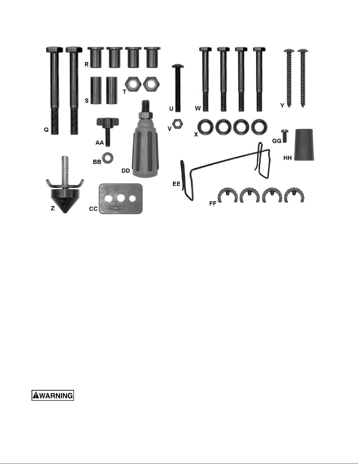
Hardware
The following items are shown in Figure 4.
Q Screw (2)
R Collar (4)
S Shaft Sleeve (2)
T Nut (2)
U Screw (1)
V Nut (1)
W Screw (4)
X Plastic Flat Washer (4)
Y Screw (2)
Figure 4 – Hardware
aZ oStand Pad (1)
AA oSplitter/Riving Knife Lock Knob (1)
BB oFlat Washer (1)
CC oSplitter/Riving Knife Plate (1)
DD oHandwheel Handle (1)
EE oPush Stick Storage Clip (1)
FF oPlastic Stop (4)
GG oScrew (1 )
HH oRear Extension Pad (1)
Read and understand all assembly instructions before attempting assembly! Failure to
comply may cause serious injury!
11
Page 12

Assembly
Note: The letter designators used in the assembly
section are the sam e as those used in the ship ping
contents and hardware s ection ( pag e 10-11) for the
purpose of simplif ying part identif ic atio n.
Stand
Stand may pop up unexpectedly
without weight of saw on stand. In order to
avoid injury, verify that the lock hook (G
7) located at the front of the stand is locked
onto the stop screw before mounting the table
saw.
Stand Pad and Pedal
Referring to figure 5:
1. Thread the stand p ad (Z) through the wing nut
(Z
1) to the bottom of the left rear leg.
Adjustment is desc r ibe d i n Sett ing up the St and
on page 17.
2. Attach the pedal (E) to the left f ront leg using
the screw (U) and hex nut (V). Secure with
10mm socket and crosspoint screwdriver.
Wheel
Referring to Figure 6:
3. Attach two collars (R
(M).
1, R2) to each roller wheel
1, Fig.
Figure 5
Figure 6
4. Attach one roller wheel assembly to the right
front leg using the bolt (Q), the shaft sleeve (S),
and the hex nut (T) as shown.
Note: Verify that the side of the wheel that h as
more ribs is facing toward the inside of the
stand.
5. Attach the other roller wheel to the right rear
leg using the same manner.
6. Tighten screw (Q) and hex nut (T) with two
17mm wrenches.
Note: Do not overtighten, because doing so will
not allow the wheels to turn.
Attaching Saw to Stand
Referring to Figure 7:
Do not cut the bands and
release the stand hook (G
is properly attached to the stand.
1. Place table saw (D) on the top of stand (G)
aligning the holes in the bas e with the holes in
the stand.
1) until the table saw
Figure 7
2. Insert four hex bolts (W) through t he plastic f lat
washers (X) and holes in base and stand.
3. Tighten all f our bolts (W ) with a 13 mm sock et,
but do not overtighten.
Note: To set up the stan d or fold down the stand,
see Setting Up The Stand and Folding The Stand
on page 17.
12
Page 13

Mounting the Saw to Work Surface
A hole to allow sawdust to fall
through must be provided when the saw is
mounted to a work surface (stand not used).
Failure to do so will cause sawdust to build up
in the motor area, which can result in fire or
damage to the motor.
Referring to Figure 8:
A
A
If the stand is not us ed, the saw must be proper ly
secured to a sturdy workbench through the four
mounting holes that are l ocated at the base of the
saw.
The surface of the table where the saw is to be
mounted must have a hole (B) that is large enough
to facilitate sawdust fall-through and removal.
1. Squ are the saw on the mounting surface, and
mark the location of the four 3/8 in. mounting
holes (A).
2. Drill pilot holes in t w o d ia go nal c orners (mark ed
(A) in the mounting surface.
3. Mark an 11x11 in. square (B), centered bet-
ween the four mounting holes (A).
4. Cut out and remove the square.
5. This opening will allo w sawdust to fall through
the saw base.
6. Place the saw on the work surface, and align
the mounting holes of the saw with the two
holes drilled in step 2.
7. Fasten the saw to the work surface using
screws (Y, Fig. 4) provided.
B
A
A
Figure 8
Do not operate this saw on the
floor. Doing so is very dangerous. Failure to
comply may cause serious injury!
Rear Table Extension
Referring to Figure 9:
1. Attach the rubber pa d (HH) to the inside of the
rear table extensi on (H). T hread t he screw (GG)
thru the rubber pad with the screwdriver. Tighten
the screw (GG).
2. Insert the two rear table ex tension tubes (J) into
the rear table extension (H). Fol low arro ws J
Note: The tubes (J) must be inserted into the
back of the extension with the ben t end last so
that the bar will hold the extension in place.
(J
4).
3. Snap plastic stops (FF
1) over the extension
tubes (J). This will ‘lock’ the tube (J) into the
extension (H). Make sure the pin in the stops fit
1, J2.
Figure 9
into the matching holes in the extension tubes.
4. Following arrows J1, J3, insert the rear table
extension into the t wo extension tube brack ets
(J
3) under the table.
5. Snap two black plastic stops (FF
2) over the end
of the rear table extension t ubes (J). Make sure
the pin in the stops fit into the matching holes in
the extension tubes.
13
Page 14

Handwheel Handle
Thread the handwhee l ha n dle (DD, Fig. 10) into the
handwheel hole (A. Fig. 10), and then tighten the
nut against the handwheel with a 10 mm wrench.
Installing the Blade
To avoid injury from an
accidental start, make sure the switch is in the
OFF position and the plug is disconnected from
the power source outlet.
Referring to Figure 11:
1. Remove the table insert (A).
2. Place the blade onto the arbor with the blade
teeth pointing forward to the front of the saw.
3. Mak e sure the bla de fits f lush against the inner
flange.
4. Clean the outer blade flange (H) and install it
onto the arbor and against the blade.
5. Thread the arbor nut onto the arbor, making
sure the flat side of the nut is against the b lad e,
then hand-tighten.
Figure 10
6. Pull the ar bor locking lever (G) toward the front
of the machine while spinning the blade by
hand until the latch locks into place and the
blade will no longer turn.
7. Place the wrench (E) on the arbor nut and tur n
clockwise (toward the rear of the saw table).
8. Lower the blade to the down position. Replace
the table insert (A) and the blade guard.
Important: Do no t operate this saw until t he blade
and blade guard spl itter are aligned and in work ing
order.
Removing the Blade
To avoid injury from an
accidental start, make sure the switch is in the
OFF position and the plug is disconnected from
the power source outlet.
Referring To Figure 11:
1. Remove the table insert (A) and raise the blade
to the maximum height by turning the blade
elevation handwheel clockwise.
2. Remove blade guard.
3. Adjust the blade to the 90° vertical position by
unlocking the blade t ilt in g lo ck knob and turning
the bevel tilting handwheel counterclockwise,
and then lock into position.
4. Pull the arbor locking lever (G) toward the front
Figure 11
of the tool while spinning the blade by hand
until the latch lock s into pl a c e and th e b lad e will
no longer turn.
5. Place the blade wrench (E) on the arbor nut (J).
6. Loosen and remove the arbor nut and the
flange by pulling the wrench towards the front
of the machine.
7. Then remove the blade (F). Clean but do not
remove the inner blade flange before
reassembling the blade.
14
Page 15
Blade Guard Assembly
To avoid injury from an
accidental start, make sure the switch is in the
OFF position and the plug is disconnected from
the power source outlet.
● When installing the blade guard, cover the
blade teeth with a piece of folded cardboard to
protect yourself from possible injury.
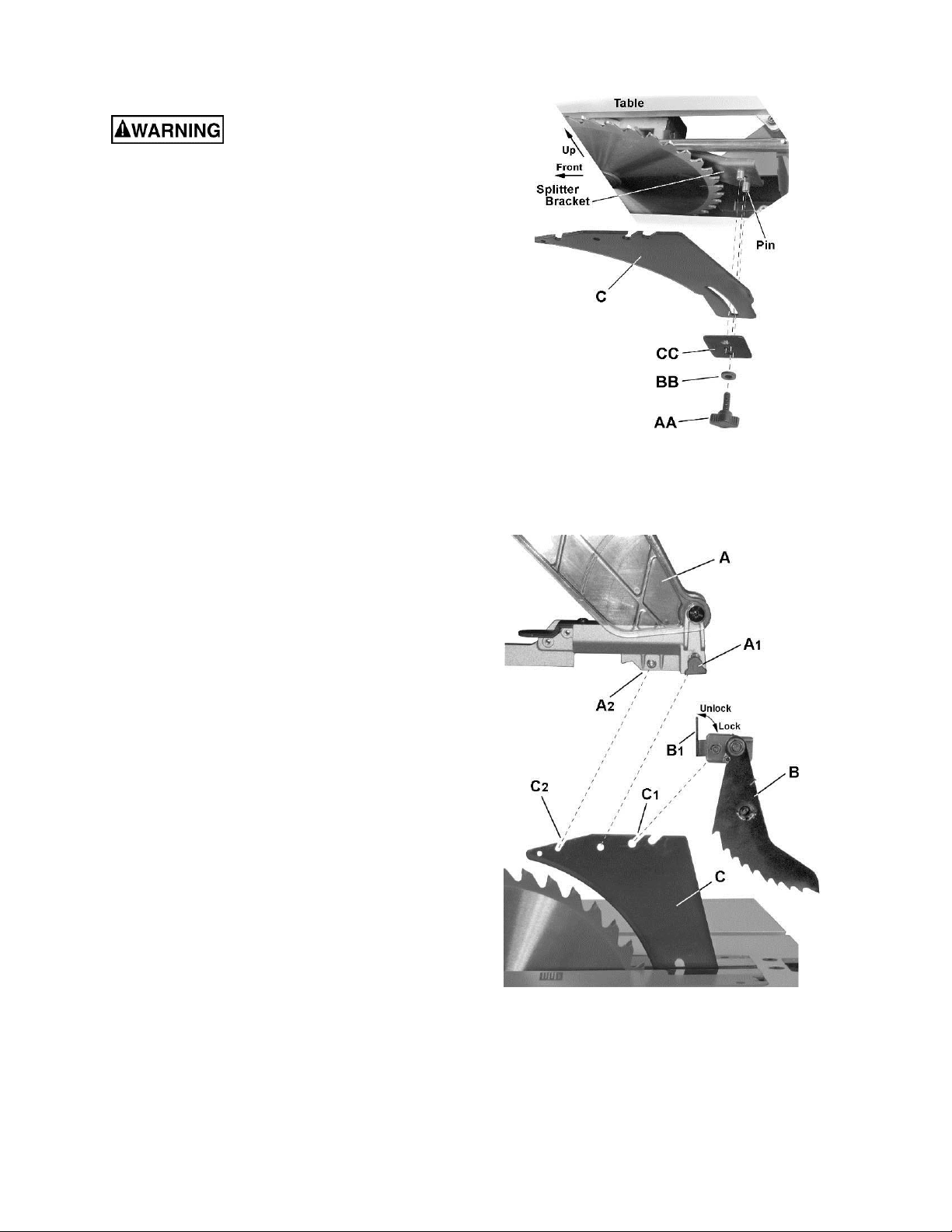
Splitter (riving knife) installation (Figure 12)
1. Remove the table insert.
2. Raise the blade arbor to the maximum height
and set the bevel angle to 0°.
3. Install the splitter (C) onto the splitter bracket,
fitting the curved slot on the splitter over the
bracket pins.
4. Install the splitter plate (CC), followed by the
flat washer (BB) and lock knob (AA). Tighten
the lock knob, leaving enough slack to
manually adjust the splitter (C).
5. Raise the splitter (C) as hi gh as it will go, then
tighten the lock knob (AA) to secure the splitter
in this position.
Figure 12
Kickback pawl installation (Figure 12a)
6. Place the lock lever (B
1) on the kickback pawl
assembly (B) in the unlock position.
7. Install the kickback pawl (B) onto the splitter.
The flat sides of the mounting pin on the
kickback pawls should pass though the
mounting slot (C1) on the splitter (C).
Note: Make sure the “anti-kickback pawls do
not get caught between the insert and the
guard, but rest on top of the insert.
8. Press firmly down on the kickback pawl to
ensure that it is prop erly seated on th e splitter,
then place the lock lever (B1) in the lock
position.
Blade guard installation (Figure 12a)
9. Slide the lock lever (A1) on the blade guard (A) up
and hold..
10. Place the blade guard (A) on the splitte r (C),
meshing t he pin (A
slot (C
2) on the splitter.
2) on the blade guard with the
11. Push the blade guard assembly down firmly on the
splitter; then release the lock lever (A
1).
12. Lift up on the blade guard assembly (A) to confirm
that it is firmly secure d to the splitte r (C).
15
Figure 12a
Page 16

Installing the Push-stick Storage
Attach the metal push-stick storage bracket (Figure 13)
into the provided slot (D, Fig. 14) on the right side of the
body shell. The bracket will snap into place.
Storage
Rip fence and miter gauge
Storage brackets f or the rip fence (B, Fig. 14) and
miter gauge (C, Fig. 14) are located on the right
side of the saw housing.
Note: Adjust the miter gauge to 45º-60º
putting away in storage.
Blade wrench
Insert the handle of th e blade wrench (A, Fig. 14)
into the slot located to the right side of the saw
housing.
before
Figure 13
D
Figure 14
Blade
1. Loosen and remove the knob (A, Fig. 15) on
the left side of the saw housing.
2. Place extra blades (B, Fig. 15) onto the
bushing. Replace the knob and tighten.
Figure 15
16
Page 17

Adjustments
Setting up the Stand
Referring to Figure 16:
1. Release the stand lock hook (D) by sliding it
away from the stop screw.
2. Raise the handle cover (A) first, then pull the
locking handle (B) out and hold.
3. Step on the pedal (C) and pull the stand
upward until it is fully unfolded.
4. Release the locking handle (B) to lock the
stand into position. Lower the cover (A).
Note: Make sure the stand is locked securely.
5. Place the stand on a level surface and adjust
the left stand pad (Z, F ig. 5) s o that all legs ar e
contacting the floor and are at a similar angle to
the floor.
Note: Make sure the table saw is locked
securely in position. Adjust the stand pad to
make sure the table saw is totally stable.
Folding the Stand
1. Raise the handle cover (A, Fig. 16) first and
pull the locking handle (B, Fig. 16) out.
Figure 16
2. Push slowly downward on the stand (A, B, Fig. 17).
3. Release the locking handle (B, Fig. 16).
4. Rotate the stand hook (D, Fig. 16) onto the
stop screw to secure the stand legs into the
collapsed positio n.
5. Secure the side exte nsion table (H, Fig. 16) b y
pushing the cam locking lever (F, Fig. 16)
downward.
Note: For convenient storage, there are two
stand up supports (G, F ig. 16) on the right s ide
of the table saw for supporting the table saw
when not in use (C, Fig. 17).
Adjusting the Table Insert
The table insert (A, Fig. 18) is already installed on
your table s a w. Verify that t h e t ab l e i ns er t is f l us h with
the table top surface on all four corne rs of the insert .
To avoid serious injury, the
table insert must be level with the table.
If the table insert is not f lush with the table, adjust
the four hex screws (B, Fi g. 18) with a 4 mm hex
wrench until it is flush with the table.
To raise the insert, turn the hex screws (B) counter-
Figure 17
Figure 18
clockwise. To lo wer the insert, tur n the hex scr ews
clockwise.
17
Page 18

Aligning the Blade Guard Splitter
To avoid injury from an
accidental start, make sure the switch is in the
OFF position and the plug is disconnected.
● When installing the blade guard, cover the
blade teeth with a piece of folded cardboard to
protect yourself from possible injury.
● Never operate this tool without the safety
guard in place for all through sawing operations.
Important: The splitter must always be correctly
aligned with the blade so the cut workpiece will
pass on either side without binding or twisting.
The splitter/riving knife is adjusted at the factory
and should not require adju s tm ent. In the e vent t hat
adjustment becomes necessary, follow the
procedure below.
Referring to Figure 19:
1. Remove the table inser t and raise the blade to
the maximum height by turning the blade
elevation handwheel clockwise.
2. Remove the blade guard and pawl assembly
(see Blade Guard Assembly on page 15)
3. Adjust the blade to the 90° vertical position by
unlocking the blade t ilt in g lo ck knob and turning
the bevel tilting handwheel counterclockwise,
and then lock into position.
4. To see if the blade (A) and splitter (B) are
correctly aligned, lay a straightedge along the
side of the blade and against the splitter
(making sure the square is between the teeth
of the blade).
The blade and spli tter should be per fectly in-line. If
the blade and splitter are not correctly aligned:
5. Loosen two screws (C) just enough to permit
adjustment of the splitter mounting bracket (D).
6. Adjust the splitter (B) until i t is aligned with the
saw blade (A), using the straightedge as
reference.
7. Tighten screws (C) and recheck alignment.
8. Replace table insert, pa wl assembly and blade
guard assembly.
18
Figure 19
Page 19

90° and 45° Positive Stop Adjustment
Adjusting the Positive Stop
Your saw has positive stops that will quickly
position the saw blade at 90° and 45° to the table.
Make adjustments only if necessary.
90° Stop
1. Disconnect the saw from the power source.
2. Raise the blade to the maximum elevation.
3. Loosen the blade bevel loc k handle. Adjust the
blade (A) to th e maximum vertical position and
retighten the bevel lock handle.
4. Place a co mbinatio n squar e (C) on the table (B)
and against the blade (A) to determine if the
blade is 90° to the table.
5. If the blade is not 90° to the table, loosen or
tighten the hex screw (G) with a 5 mm hex
wrench until 90° is achieved.
6. Loosen the bevel lock handle and reset the
blade at the maximum vertical position, then
tighten the bevel lock handle.
7. Check again to see if the blade is 90° to the
table. If not, repeat step 5.
8. Check the bevel angle scale. If the pointer does
not read 0°, loosen the scr ew that secures the
pointer, adjust to read 0°, retighten the pointer
screw.
45° Stop
1. Disconnect the saw from the power source.
2. Raise the blade to the maximum elevation.
Figure 20
3. Loosen the blade bevel loc k handle. Adjust the
blade (D) to the m aximum bevel position (45°)
and retighten the bevel lock handle.
4. Place a combination square (F ) on the table (E)
and against the blade (D) to determine if the
blade is 45° to the table.
5. If the blade is not 45° to the table, loosen or
tighten the hex screw (H) with a 5 mm hex
wrench until 45° is achieved.
6. Loosen the bevel lock handle and reset the
blade at the maximum bevel position (45°),
then tighten the bevel lock handle.
7. Check again to see if the blade is 45° to the
table. If not, repeat step 5.
Blade Tilt Pointer
When the blade is positioned at 90°, loosen the
holding screw, adjust the blade tilt pointer to read
0° on the scale, then retighten the screw.
19
Figure 21
Page 20

Blade Parallel to the Miter Slot
Additional Blade Adjustments
To avoid injury from an
accidental start, make sure the switch is in the
OFF position and the plug is disconnected from
the power source outlet.
This adjustment was made at the factory, but it
should be rechecked and adjusted if necessary.
This adjustment m us t be correc t to assur e accur ate
cuts and to prevent the possibility of kickback,
which can result in serious injury.
Referring to Figure 22:
1. Re move the yellow switch key and unplug the saw.
2. Remove the blade guard.
3. Raise the blade to the m axim um height and set
the bevel angle at 0°
4. Select and mark with a felt tip marker, one
blade tooth with a “right set ” angle and pos ition
this tooth at the front of the saw approximately
1/2 in. above the table (D) .
Refer to Figure 23.
If the front and rear measurements are not the
same:
1. Remove the combination square (C) and
loosen the four adjusti ng screws (A) on th e top
of the table about a half turn.
2. Cover the blade with a folded piece of
cardboard to protect your hands. Move the
blade and motor mounting rod carefully to the
left or right as much as needed to align the
blade correctly.
3. Tighten the four screws (A) and rem easure, as
described in steps 4 to 9 in the previous section.
Figure 22
5. Place the combinatio n squar e bas e (G) into the
right side miter gauge slot (F ) flush against the
inside of the miter gauge slot.
6. Adjust the ruler (E) so it touches the front
marked tooth (D) and lock ruler so it holds its
position in the square assembly.
7. Nex t rotate the b lade, m oving the m arked tooth
(D) to its new position (A) at the rear of the
saw.
8. Carefully move the combination square from
position (G) to (C).
9. If the ruler touches the marked tooth at the
front and rear position (E at D, B at A), no
adjustment is needed. If not, perform the
adjustment procedure described in the next
section.
Figure 23
4. If sufficient adjus tment cannot be made b y the
four adjusting scr ews (A), then also loos en the
two adjusting screws (B) and repeat all
previous steps. Loos en these screws (B) only if
necessary as the y are set for ac curate 90° a nd
45° settings.
5. Recheck the bla de clearance mak ing sure that
the blade does not hit t he table insert or other
parts when at the 90° and 45° settings.
6. Retighten all four adjusting screws (A) and
reset the 90° and 45° setting as described in
the 90° and 45° Positive Stop Adjustment
section (page 19).
20
Page 21

Adjusting the Miter Gauge
Referring to Figure 24:
1. Loosen the lock handle (B) to allow the miter
body (C) to rotate freely. Position the miter
body at 90° so the positive detent secures its
position. Tighten th e loc k hand le (B) to hold the
miter body in position.
2. If the pointer (A) requires adjustment, loosen
the screw under the poi nter with a screwdr iver.
Adjust the pointer to 90° on the scale, then
firmly tighten the adjustment screw.
To change angles on the miter gauge:
3. Loosen the loc k handle ( B) and rotat e the miter
body to the desired angle as indicated by the
scale. Secure in pos ition by tightening the lock
handle.
Rip Fence Adjustment
Referring to Figure 25:
1. For adjustm ents, position the f ence to the right
of the blade, parallel with the miter gauge slot.
2. Place the rear clamp (A) of the fence on the
back rail of the table, and lower the front end
over the front rail (E). Push the handle (F)
down to lock.
3. T o change the position of the fence, lift up on
the handle to unlock , and slide the f ence to the
desired position, th en push the hand le down to
lock.
4. To check the rip fence adjustment, place the
fence along one edge of the miter gauge
groove, and lock the handle. It should be
parallel to the miter groove to provide accura te
cuts.
If an adjustment is needed to make it parallel:
1. Loosen the two hex bolts (C) on the top of the
rip fence, and lift up on the handle (F).
2. Adjust the fence ( B) so it is parallel to t he miter
gauge slot and lock the handle (F) into position.
3. Make sure the fence (B) is parallel to the slot
and tighten the two hex bolts (C) securely.
4. Unlock the fence handle (F) and slide th e fenc e
left and right, then reposition it against the miter
gauge slot again and lock into position to
double check its alignment.
Failure to properly align the fence can cause
“kickback” and serious injury could occur.
Figure 24
Figure 25
If the fence is loose when the handle is in the
locked position:
1. Move the handle upward to the unlocked
position.
2. Turn the adjusting scr ew (D) clock wise until th e
rear clamp is snug.
3. Do not turn the adjusti ng screw more than 1/4
turn at a time.
4. Over-tightening the screw will cause the rip
fence to come out of alignment.
21
Page 22

Rip Fence Indicator
The rip fence indicator points to the scale on the
front of the table saw. The m easurement shown b y
the indicator wil l provide the user with accurac y up
to 1/16 of an inch. The m easurement shown is the
distance from the blade to the side of the fence
closest to the blade.
To check the accuracy:
1. Measure the actual distance to the side of the
rip fence.
If there is a difference between the measurement
and the indicator, adjust the indicator as follows:
2. Loosen the indicator screw (A, Fig. 26).
3. Slide the indicator to th e correct measurement
position on the scale, then retighten the screw.
Table Extension Scale Pointer
The table extension scale pointer (A, Fig. 27)
should be at 13 inches on the scale when the
extension is in the closed position. If adjustment is
required, loosen the holding screw (B, Fig. 27),
position the pointer over the 13 inch m ark er and r etighten the screw.
Rear Table Extension Adjustment
The rear table extension (A, Fig. 28) should be
positioned as close as possible to the rear of the
table when ripping short material.
Figure 26
Figure 27
The rear table extension should be fully extended
when ripping longer materials that require extra
support.
Adjusting the Locking Lever
If the extension table moves when it is open and
locked in place, the cam locking lever (A, Fig. 29)
may be loose and require adjustment.
To adjust the locking lever tension:
1. Hold the stud (B) stationar y, and loos en the nut
(C) with a 10 mm wrench.
2. Rotate the rod using a wrench on one of the
flats (D). Do not overtension!
3. Re-tighten the nut (C).
22
Figure 28
Figure 29
Page 23

Operation
Basic Saw Operations
Raising the Blade
To raise or lower the blade , turn the blade elevat ion
handwheel (A, Fig. 30) to the desire d blade height,
and then tighten the bev el lock handle ( B, Fig. 30) to
maintain the desired blade angle.
Figure 30
Tilting the Blade
Two methods are available for tilting the saw blade.
Rapid blade tilting:
Loosen the bevel loc k handle (B, F ig. 30), move the
handwheel (A, Fig. 30) to the desired angle, then
tighten the bevel lock handle.
Fine adjustment blade tilting:
Loosen the bevel lock handle (B, Fig. 30), push in
the handwheel (A, Fig. 30) and at th e s ame time turn
the handwheel (A, Fig. 30) to tilt the saw blade.
When the saw blade is at t he desired angle, tighten
the bevel lock handle (B, Fig. 30).
5. If the removab le safet y key is r emoved wh ile the
saw is running, it c an be turned OFF but cannot
be restarted without inserting the removable
safety key (A).
Figure 31
Overload Protection
This saw has an overload reset button (C, Fig. 31)
that resets the motor after it shuts off due to
overloading or low vo ltage. If the m otor stops during
operation, turn the ON / OFF switch to the OFF
position. Wait about five minutes for the motor to
cool, the push the res et button (C, Fig. 31) a nd turn
the switch to the ON position.
Dust Chute
To prevent fire hazard, clean and remove
sawdust from under the saw frequently.
To prevent sawdust bui ldup inside the sa w housing,
attach a vacuum hose (A, Fig. 32) to the dust chute
(B, Fig. 32) at the rear of the table saw. DO NOT
operate the saw with the hose in place unless the
vacuum is turned on.
On/Off Switch
The ON / OFF switch has a removable safety key.
With the key removed fr om the switch, unauthori zed
and hazardous use by children and others is
minimized.
Referring to Figure 31:
1. To tur n the saw ON, ins ert the saf ety switch k ey
(A) into the slot in the switch (B). Move the
switch upward to the ON position.
2. To turn the saw OFF, move the switch
downward.
3. To lock the switch in the O FF pos ition, grasp th e
end (or yellow par t) of the safet y switch key (A),
and pull it out.
4. With the removable safety key removed, the
switch will not operate.
Figure 32
Using the Table Extension
Use the scale on the front rail for rip cuts up to 13 in.
For rip cuts greater than 1 3 in., set and the lock the
fence on the 13 in. m ark. Unlock the extension tab le ,
and slide the table with the fence to the desired
dimension using the scale on the rear rail.
Referring to Figure 33:
1. Release the cam locking lever (A).
2. Slide the table extension to the desired
measurement and the n tighten the cam locking
lever.
23
Page 24

Figure 33
Cutting Operations
1. Remove the miter gauge and store it in the
“storage” compartment in the base of the saw.
2. Secure the rip fence to the table.
3. Raise t he blade so it is about 1/8 i n. higher than
the top of the workpiece.
4. Place the workpiece flat o n the ta bl e an d a gai ns t
the fence. Keep the workpiece away from the
blade.
5. T urn the sa w ON and wait for the blade to com e
to full speed.
6. Slowly feed the workpiece into the blade by
pushing forward only on the workpiece section
(A, Fig. 34) that will pass between the blad e and
the fence.
There are two basic types of cuts: ripping and
crosscutting. Ripping is cutting along the length and
the grain of the workpiece. Crosscutting is cutting
either across the width or across the grain of the
workpiece. (It is not safe to rip or crosscut by
freehand). Ripping re quires the use of the rip f ence,
and crosscutting requires the miter gauge. NEVER
USE THE TWO AT THE SAME TIME.
Before using the saw each time,
check the following:
• The blade is tightened to the arbor.
• The bevel angle lock knob is tightened.
• If ripping, make sure the fence is locked into
position and is parallel to the miter gauge
slot.
• The blade guard is in place and working
properly.
• Safety glasses are worn.
• The failure to adhere to these common safety
rules, and those printed in the front of this
manual, can greatly increase the likelihood
of injury.
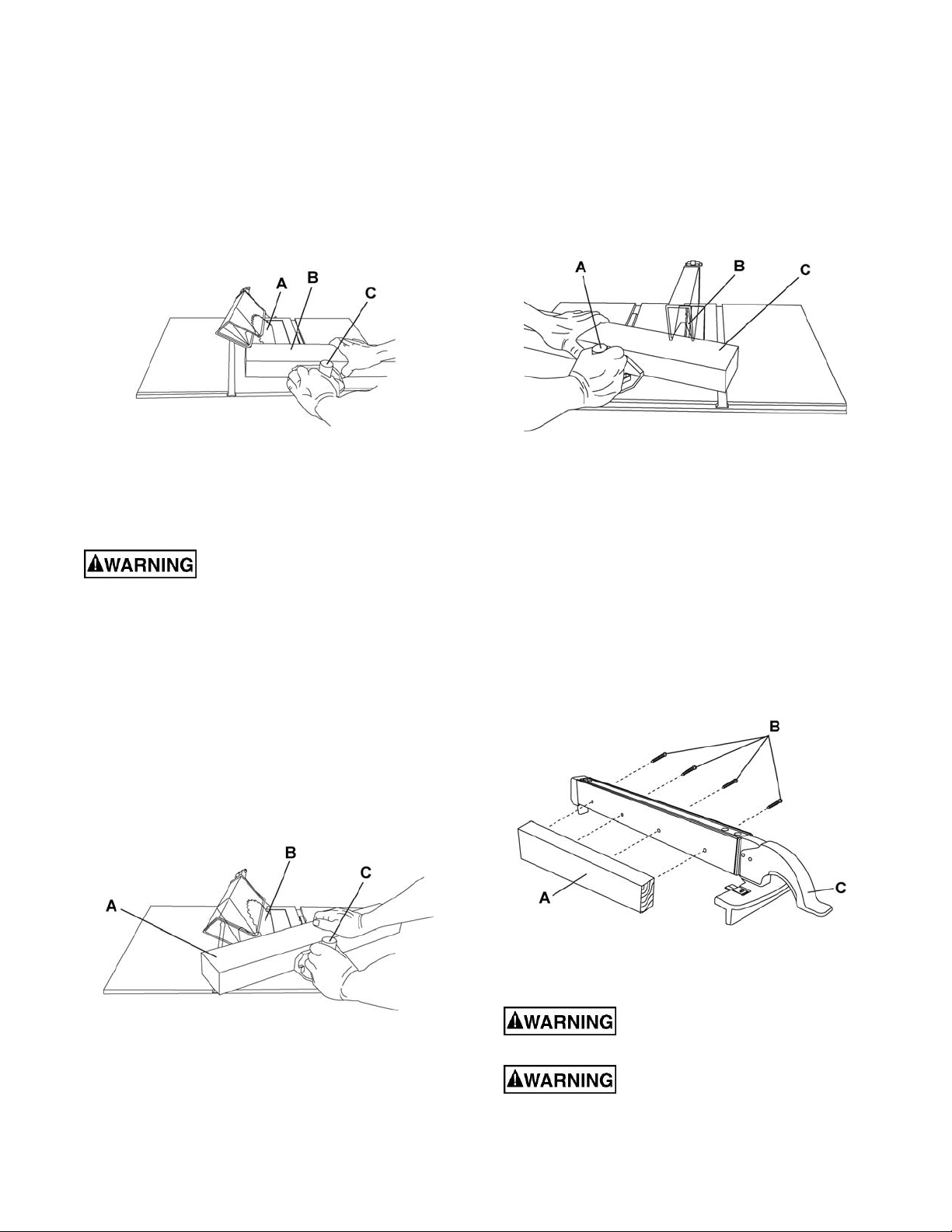
Ripping
AVOID KICKBACK by pushing
forward on the section of the workpiece that
passes between the blade and the fence. Never
perform any freehand operations.
Figure 34
Referring to Figure 35:
7. Keep your thum bs of f the t a ble t op. W hen bot h of
your thumbs touch t he f ront edg e of the t abl e (C),
finish the cut with a push stick. To make an
additional push stick, use the pattern on page 29.
8. The push stick (D) should always be used for
any ripping operation.
To prevent serious injury:
• Never use a miter gauge when ripping.
• Never use more than one rip fence during a
single cut.
• Do not allow familiarity or frequent use of
your table saw to cause careless mistakes.
Remember that even a careless fraction of a
second is enough to cause a severe injury.
• Keep both hands away from the blade and
clear from the path of the blade.
• The workpiece must have a straight edge
against the fence and must not be warped,
twisted, or bowed when ripping.
9. Continue pushing the workpiece with the push
stick (D) until it passes through th e blade guard
and clears the rear of the table.
10. Never pull the piece back when the blade is
turning. Turn the switch OFF. When the blade
completely stops, you can then remove the
workpiece.
Never attempt to pull the
workpiece backwards during a cutting operation.
This will cause kickback and serious injury to
the user can occur. When the blade completely
24
Page 25

stops, raise the anti-kickback pawls (A) on each
side of the splitter and slide the workpiece out.
Figure 35
4. Start the s aw and wait for the bl ade (C) to com e
up to full speed. Never stand directly in line of
the saw blade path, a lways stand to the side of
the blade that you are cutting on.
5. Kee p the workpiece (B) against the f ace of the
miter gauge (A) and flat against the table . Then
slowly push the workpiece through the blade.
6. Do not try to pull the workpiece back with the
blade turning. Turn the switch OFF, and
carefully slide the work piece out when the blade
has completely stopped.
Always position the larger surface
of the work-piece on the table when crosscutting
and/or bevel crosscutting to avoid instability.
Bevel Ripping
This cut is the same as ripping except the blade
bevel angle is set to an angle other than “0º.
Ripping Small Pieces
To avoid injur y from blade c ontact, never m ake cuts
narrower than 1/2 in. wide.
1. It is unsafe to rip small pieces. Instead, rip a
larger piece to obtain the size of the desired
piece.
2. When a small width is to be ripped and your
hand cannot safel y pass between the blad e and
the rip fence, use one or more push sticks to
move the workpiece. Always use a push stick
during ripping operations.
Crosscutting
Do not allow familiarity or
frequent use of your table saw to cause careless
mistakes. Remember that even a careless fraction
of a second is enough to cause a severe injury.
Keep both hands away from the
blade and the path of the blade.
Figure 36
Using Wood Facing on the Miter Gauge
Slots are provided in the miter gauge for attaching
an aux iliary facing (A) to make it easier to cut very
long or short pieces. Select a suitable piece of
straight wood, drill two holes through it and attach it
to the miter gauge with scre ws. Make sure the facing
does not interfere with the proper operation of the
sawblade guard. When cutting long work pieces, you
can make a simple outfeed support by clamping a
piece of plywood to a sawhorse.
Never attempt to pull the
workpiece backwards during a cutting operation.
This will cause kickback and serious injury to the
user can occur.
Referring to Figure 36:
1. Rem ove the rip fenc e and plac e the m iter gauge
in the miter gauge slot on the table.
2. Adj ust the blade he ight so that it is 1/8 in. hig her
than the top of the workpiece.
3. Hold the workpiece firmly against the miter
gauge with the blade path in line with the
desired cut location.
Figure 37
Bevel Crosscutting 0°~45° Blade Level & 90° Miter
Angle
This cutting operation is the same as crosscutting
except the blade is at a bevel angle other than 0°.
Always work to the right side of
the blade during this type of cut. The miter
gauge must be in the right side slot because the
bevel angle may cause the blade guard to
25
Page 26
interfere with the cut if used on the left side
groove.
1. Set th e blade (B) to 0° bevel angle and tighten
the blade bevel lock knob.
Referring to Figure 38:
1. Adjust the blade (A) to the desired angle, and
tighten the blade bevel lock k nob.
2. Tighten the miter lock handle (C) at 90°.
3. Hold workpiece (B) firmly against the f ace of the
miter gauge throughout the cutting operation.
Figure 38
Compound Miter Crosscutting 0°~45° Blade Bevel
& 0°~45 Miter Angle
This sawing operation c ombin es a m iter angle with a
bevel angle.
Always work to the right side of
the blade during this type of cut. The miter
gauge must be in the right side groove because
the bevel angle may cause the blade guard to
interfere with the cut if used on the left side
groove.
1. Set the miter gauge (C) to the desired angle.
2. Place t he miter gauge in the r ight side groove of
the table.
2. Set the miter gauge (A) at the desired miter
angle and lock in posit ion by tig htening th e miter
gauge locking handle.
3. Hold the work piece (C ) firml y against th e face of
the miter gauge throughout the cutting
operation.
Figure 40
Using the Wood Facing on the Rip Fence
When performing some special cutting operations,
you can add a wood f acing to either side of the rip
fence (C, Fig. 41).
1. Use a sm ooth straight 3/4 in. thick wood board
(A, Fig. 41) that is as long as the rip fence.
2. Attach the wood facing to the fence with wood
screws (B, Fig. 41) (not included) through the
holes in the fence. A woo d f enc e s hould be us e d
when ripping material such as thin paneling to
prevent the material f rom catching between the
bottom of the fence and the table.
3. Set the blade (B) bevel to the desired bevel
angle and tighten the blade bevel lock knob.
4. Hold workpiece (A) firmly against the f ace of the
miter gauge throughout the cutting operation.
Figure 39
Mitering 0°~45° Miter Angle
This sawing operation is the same as crosscutting
except the miter gauge is locked at an angle other
than 90°.
Figure 41
Dado Cuts
The maximum dado cut width is 13/16 in.
Only Stackable dado blades can
be used on this saw.
DO NOT use Adjustable or Wobble
type dadoes.
Referring to Figure 42:
26
Page 27

1. Remove the saw blade and the blade g uard for
dado cuts ONLY. Reinstall and realign blade
guard for all thr ough- sawing operations. Instal l
a dado not exceeding 6 in. diameter and 13/16
in. width.
2. Install a dado table insert m aking sure that the
rear of the insert is flush with the table.
Note: A dado table insert i s not inc luded b ut can
be ordered (SN 707001) by calling th e number
on the cover of this manual.
3. Instructions for operating the dado is packed
with the separately purchased dado set.
4. T he arbor (B) on this saw res tricts the m axim um
width of the cut to 13/16 in.
5. It is not necessar y to install the outs ide flange (A)
before threading on the arbor nut (C) for the
maximum 13/16 in. dado cuts. Make sure that the
arbor nut (C) is ti ght, and th at at least on e thread
of the arbor sticks out past the nut.
6. Use only the correct number of round outside
blades and inside chippers as shown in the dado
set’s instruction manual. Blade/chippers must
not exceed 13/16 in. total in width.
7. Check the saw to ensure that the dado will not
strike the housing, insert, or motor when in
operation.
For your own safety, always
replace the blade, blade guard assembly, and
table insert when you are finished with the dado
operation.
Figure 42
27
Page 28

Maintenance
General Maintenance
For your own safety, turn the
switch OFF and remove the switch key. Remove
the plug from the power source outlet before
maintaining or lubricating your saw.
1. Clean out all sawdust that has accumulated
inside the saw cabinet and the motor.
2. Polish the saw table with an autom otive wax to
keep it clean and to m ake it easier to slide the
workpiece.
3. Clean cutting blades with pitch and gum
remover.
4. A worn, cut, or damaged power cord should be
replaced immediately.
All electrical or mechanical
repairs should be attempted only by a trained
repair technician. Contact customer service for
assistance. Use only identical replacement parts.
Any other parts may create a hazard.
5. Use liquid dishwashing detergent and water to
clean all plastic parts.
Note: Certain cleaning chemicals can damage
plastic parts.
6. Avoid use of cleaning chemicals or solvents,
ammonia and household detergents containing
ammonia.
Figure 43
If excessive loosen ess is obs erved in an y part of the
blade raising m echanism or tilting mechanis m, take
the complete unit to a Service Center.
Lubrication
All motor bearin gs are perm anently lubricat ed at the
factory and require no additional lubrication.
On all mechanical parts of your table saw where a
pivot or threaded rod is present, lubricate using
graphite or silicone. These dry lubricants will not
hold sawdust as would oil or grease.
Replacing the Carbon Brushes
Blade Raising and Tilting Mechanism
After ever y five hours of operation , the blade raising
mechanism and t ilting m echan ism s hould be chec k ed
for looseness, binding, or any other abnormalities.
Referring Figure 43:
1. With the saw disconnected from the power
source, turn the saw upside down and pull up
and push down on the motor unit.
2. Observe any movement of the motor mounting
mechanism. Looseness or play in the blade raising
screw rod (A) should be limited to 1/8 ” or less.
3. If excessive loose ness is observed in any other
parts of the blade raising mechanism or tilting
mechanism, tak e the complete unit to a Ser vice
Center.
Place a small am ount of dry lubricant on the bevel
gear (B). The screw rod (A ) must be kept clean and
free of sawdust, gum , pitch, and o ther contaminants
for smooth operations.
Always disconnect the plug from
the power source before inspecting the brushes.
The carbon brushes included with the unit will last
approxim atel y 50 hours of r unning t ime, or 1 0,000 O N/
OFF cycles. Re place bo th carbo n brush es when e ither
has less th an 1/4 in. lengt h of carbon rem aining, or if
the spring or wire is damaged or burned.
1. Remove the blad e guard, blade, rip fenc e, miter
gauge and stand assembly from the table saw.
2. Place cardboard or an old blank et on the f loor to
protect the saw table surface.
3. Place the saw upside down on the protective
material.
4. Tilt the blade elevation/tilting handwheel (A, Fig. 44)
to the 45° position.
28
Page 29
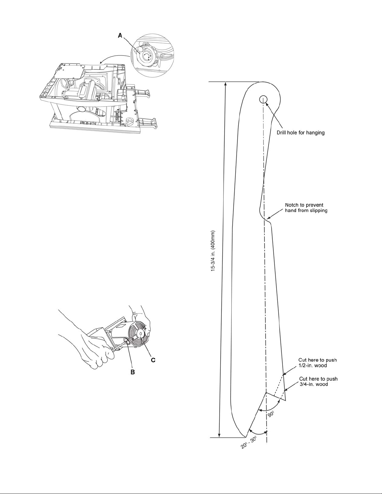
Figure 44
5. Referring to Figure 45:
6. Remove the black plastic cap ( B) from the side
of the motor (C).
7. Carefully remove the spring-loaded cap, and
then pull out the brush and replace.
8. Replace the other side.
9. The ears on the metal end of the as sembl y go in
the same hole the carbon part fits into. Do not
overtighten the plastic cap.
Push Stick Construction
Use solid wood or good quality plywood to construc t
a push stick using the template below. The push
stick must be thinner than the width of the m aterial
being cut.
10. Carefully set the saw in an upright position on a
clean level surface.
11. Replace the blade g uard, blade, r ip fence, miter
gauge and stand assembly to the table saw.
Note: To reinstall the same brushes, first make sure
the brushes go bac k in the way they came out. This
will avoid a break-in period that reduces motor
performance and increases wear.
Figure 45
Lubrication
All motor bearin gs are perm anently lubricat ed at the
factory and require no additional lubrication.
On all mechanical parts of your table saw where a
pivot or threaded rod is present, lubricate using
graphite or silico ne. These dr y lubricants will not hold
sawdust as would oil or grease.
29
Figure 46
Page 30

Troubleshooting
Trouble Probable Cause Remedy
Saw will not start.
Does not make
accurate 45° and
90° rip cuts.
Material pinched
blade when ripping.
Material binds on
splitter.
Saw makes
unsatisfactory cuts.
Material kicked
back from blade.
Blade does not
raise or tilt freely.
Blade does not
come up to speed.
Reset trips too
easily.
Machine vibrates
excessively.
Does not make
accurate 45° and
90° crosscuts.
Anti-kickback pawls
catch on the table
insert opening.
1. Saw is not plugged in.
2. Fuse blown or circuit breaker
tripped.
3. Cord is damaged.
4. Debris in on/off switch
1. Positive stop not adjusted
correctly.
2. Tilt angle pointer not set
accurately.
1. Rip fence not aligned with blade.
2. Warped wood, edge against fence
is not straight.
1. Splitter not aligned correctly with
blade.
1. Dull blade.
2. Blade mounted backwards.
3. Gum or pitch on blade.
4. Incorrect blade for work being
done.
5. Gum or pitch on blade causing
erratic feed.
1. Rip fence out of adjustment.
2. Splitter not aligned with blade.
3. Feeding stock without rip fence.
4. Splitter not in place.
5. Dull blade.
6. The operator letting go of material
before it is past saw blade.
7. Miter angle lock knob is not tight.
1. Sawdust and dirt in elevation/tilting
mechanisms.
1. Extension cord too light or too
long.
2. Low house voltage.
1. Saw not mounted securely to
workbench.
2. Bench on uneven floor.
3. Damaged saw blade.
1. Miter gauge out of adjustment. 1. Adjust miter gauge.
1. Splitter/riving knife not set in full
raised position.
1. Plug in saw.
2. Replace fuse or reset circuit breaker.
3. Replace power cord.
4. Remove switch from saw and
separate in half. Clean any debris
accumulated within.
1. Check blade with square and adjust
positive stop.
2. Check blade with square and adjust
to zero.
1. Check and adjust rip fence.
2. Select another piece of wood.
1. Check and align splitter with blade.
1. Replace blade.
2. Turn the blade around.
3. Remove blade and clean with
turpentine and coarse steel wool.
4. Change the blade.
5. Clean or change blade.
1. Align rip fence with miter gauge slot.
2. Align splitter with blade.
3. Install and use rip fence.
4. Install and use splitter. (with guard)
5. Replace blade.
6. Push material all the way past saw
blade before releasing work.
7. Tighten knob.
1. Brush or blow out loose dust and dirt.
1. Replace with adequate size cord.
2. Contact your electric company.
1. Tighten all mounting hardware.
2. Reposition on flat level surface.
3. Replace blade.
1. Set splitter/riving knife to full raised
position using the blade elevation
handwheel.
30
Page 31

Parts
Ordering Replacement Parts
Replacement parts are lis ted on the followin g pages. To order par ts or reach our servic e department, call 1- 800274-6848 Monday throu gh Friday, 8:00 a.m. to 5:00 p .m. CST. Having the Mod el Number and Serial Num ber of
your machine available when you call will allow us to serve you quickly and accurately.
JBTS-10MJS Table Saw – Parts List
Note: Parts without part numbers are for reference only and cannot be purchased individually.
Index No. Part No. Description Size Qty
1 ............... JBTS10MJS-1 .......... Bushing ................................................................ ............ ........................ 1
2 ............... JBTS10MJS-2 .......... Cable Clamp ........................................................ .................................... 1
3 ............... JBTS10MJS-3 .......... Slide Plate ............................................................ ............ ........................ 2
4 ............... ................................. Cushion Block ...................................................... .... ................................ 4
5 ............... JBTS10MJS-5 .......... Cord Clamp .......................................................... ............... ..................... 1
6 ............... JBTS10MJS-6 .......... Bracket ................................................................. .................................... 1
7 ............... JBTS10MJS-7 .......... Spacer .................................................................. .................................... 1
8 ............... JBTS10MJS-8 .......... Bracket ................................................................. .................................... 1
9 ............... JBTS10MJS-9 .......... Dust Housing Cover ............................................. .................................... 1
10 ............. JBTS10MJS-10 ........ Strap ..................................................................... .................................... 3
11 ............. JBTS10MJS-11 ........ Washer ................................................................. .................................... 2
12 ............. JBTS10MJS-12 ........ Push Stick Holder ................................................ .................................... 1
13 ............. JBTS10MJS-13 ........ Wrench ................................................................. .................................... 1
14 ............. JBTS10MJS-14 ........ Compression Spring ............................................ .................................... 1
15 ............. ................................. Compression Spring ............................................ .................................... 1
16 ............. ................................. Pin ........................................................................ .................................... 1
17 ............. ................................. Screw ................................................................... .................................... 1
18 ............. JBTS10MJS-18 ........ Warning Label ...................................................... .................................... 1
19 ............. JBTS10MJS-19 ........ Bevel Gear ........................................................... .................................... 1
20 ............. JBTS10MJS-20 ........ Bushing ................................................................ .................................... 3
21 ............. JBTS10MJS-21 ........ Strap ..................................................................... .................................... 1
22 ............. JBTS10MJS-22 ........ Strap ..................................................................... .................................... 4
23 ............. JBTS10MJS-23 ........ Collar .................................................................... .................................... 1
24 ............. JBTS10MJS-24 ........ Collar .................................................................... .................................... 1
25 ............. JBTS10MJS-25 ........ Arbor Nut .............................................................. .................................... 1
26 ............. JBTS10MJS-26 ........ Arbor Collar .......................................................... .................................... 1
27 ............. JBTS10MJS-27 ........ Stop ...................................................................... .................................... 4
28 ............. JBTS10MJS-28 ........ Slide Base, Left .................................................... .................................... 1
29 ............. JBTS10MJS-29 ........ Foam Strip............................................................ .................................... 2
30 ............. JBTS10MJS-30 ........ Bevel Gear ........................................................... .................................... 1
31 ............. TS-152705 ............... Hex Wrench ......................................................... M4 ............................... 1
32 ............. TS-152706 ............... Hex Wrench ......................................................... M5 ............................... 1
33 ............. TS-1550031 ............. Flat Washer .......................................................... M5 ............................... 4
34 ............. TS-1550041 ............. Flat Washer .......................................................... M6 ............................... 3
35 ............. TS-1550061 ............. Flat Washer .......................................................... M8 ............................... 4
36 ............. TS-2360121 ............. Flat Washer .......................................................... M12 ............................. 1
37 ............. ................................. Flat Washer .......................................................... Ø6x18x1.5 .................. 1
38 ............. JBTS10MJS-38 ........ Flat Washer .......................................................... Ø8.2x18x2 .................. 2
39 ............. JBTS10MJS-39 ........ Flat Washer .......................................................... Ø6x30x2 ..................... 2
40 ............. JBTS10MJS-40 ........ Flat Washer .......................................................... 3/16x3/4x1/16 ............. 4
41 ............. JBTS10MJS-41 ........ Pan Head Tapping Screw .................................... M5-16x12 .................... 1
42 ............. JMS10SCMS-33 ...... Flat Washer .......................................................... 1/4x1/2x3/32 ............... 2
43 ............. JBTS10MJS-43 ........ Label: Reset ......................................................... .................................... 1
44 ............. JBTS10MJS-44 ........ Flat Washer .......................................................... 3/8x3/4x5/64 ............... 2
45 ............. ................................. Flat Washer .......................................................... 1/4 ............................... 1
46 ............. TS-2361061 ............. Lock Washer ........................................................ M6 ............. .................. 1
31
Page 32

JBTS-10MJS Table Saw
Index No. Part No. Description Size Qty
47 ............. JMS10SCMS-36 ...... External Tooth Lock Washer ................................ M5 ............................... 1
48 ............. ................................. Spring Pin............................................................. Ø4x10 ......................... 2
49 ............. JBTS10MJS-49 ........ Hex Head Bolt ...................................................... M6x70 ......................... 1
50 ............. ................................. Socket Head Cap Screw ...................................... M6x30 ......................... 1
51 ............. TS-1523011 ............. Socket Set Screw ................................................. M6x6 ........................... 6
52 ............. ................................. Socket Set Screw ................................................. M6x10 .. ....................... 1
53 ............. TS-1514041 ............. Flat Head Socket Screw ...................................... M6x25 ......................... 4
54 ............. JBTS10MJS-5 4 ........ Soc Hd Cap Screw with Lock Washer ................. M6x16 ......................... 2
55 ............. ................................. Soc Hd Cap Screw with Lock and Flat Washers . M5x16 ......................... 2
56 ............. TS-150304 1 ............. Socket Head Cap Screw ...................................... M6x 16 ......................... 4
57 ............. TS-150304 1 ............. Socket Head Cap Screw ...................................... M6x 16 ......................... 4
58 ............. JMS10CMS-149 ....... Pan Head Screw with Lock Washer .................... M5x10 ......................... 1
59 ............. JBTS10MJS-5 9 ........ Pan Head Screw w/ Ext. Tooth Lock Washer ...... M5x12 ......................... 1
60 ............. ................................. Flat Head Screw .................................................. M4x8 ... ........................ 2
61 ............. JBTS10MJS-61 ........ Pan Head Tapping Screw .................................... M4-18x8 ...................... 2
62 ............. ................................. Truss Head Screw ............................................... M5x8 ........................... 2
63 ............. JMS12SCMS-81 ...... Round Washer Head Screw ................................ M5x8 ........................... 3
64 ............. JBTS10MJS-64 ........ Round Washer Head Screw ................................ M6x12 ......................... 6
65 ............. JBTS10MJS-65 ........ Truss Head Tapping Screw ................................. M4-16x12 .................... 2
66 ............. JBTS10MJS-66 ........ Pan Head Tapping Screw .................................... M4-18x20 .................... 7
67 ............. ................................. Truss Head Tapping Screw ................................. M5-12x16 .................... 2
68 ............. ................................. Truss Head Tapping Screw ................................. M5-12x12 .................... 2
69 ............. JBTS10MJS-69 ........ Screw ................................................................... M5x25 ......................... 4
70 ............. JBTS10MJS-70 ........ Pan Head Tapping Screw .................................... M3-24x6 ...................... 2
71 ............. JBTS10MJS-71 ........ Pan Head Tapping Screw .................................... M4-18x8 ...................... 8
72 ............. JBTS10MJS-72 ........ Pan Head Tapping Screw .................................... M4-16x16 .................... 2
73 ............. JBTS10MJS-73 ........ Pan Washer Head Screw ..................................... M5x10 ......................... 5
74 ............. ................................. Pan Head T apping Sc re w .................................... M4-18x10 .................... 4
75 ............. JBTS10MJS-75 ........ Round Washer Head Screw ................................ M5x10 ......................... 9
76 ............. JBTS10MJS-76 ........ Round Washer Head Screw ................................ M5x12 ......................... 8
77 ............. JBTS10MJS-77 ........ Round Washer Head Screw ................................ M5x16 ......................... 4
78 ............. JBTS10MJS-78 ........ Strain Relief.......................................................... .................................... 2
79 ............. TS-1533042 ............. Pan Head Screw .................................................. M5x12 ......................... 3
80 ............. TS-1533062 ............. Pan Head Screw .................................................. M5x20 ......................... 1
81 ............. JWBS10OS-110 ....... Carriage Bolt ........................................................ M6x16 ......................... 2
82 ............. P WBS14-323 ........... Carriage Bolt ........................................................ M8x16 ......................... 1
83 ............. JBTS10MJS-83 ........ Carriage Bolt ........................................................ M6x60 ......................... 1
84 ............. JBTS10MJS-84 ........ Slide Base Assembly, Left ................................... .................................... 1
85 ............. TS-1540041 ............. Hex Nut ................................................................ M6 ............................... 4
86 ............. ................................. Hex Nut ................................................................ M10 ............................. 1
87 ............. TS-1540061 ............. Hex Nut ................................................................ M8 ............................... 1
88 ............. TS-1540041 ............. Hex Nut ................................................................ M6 ............................... 2
89 ............. JBTS10MJS-89 ........ Crown Nut ............................................................ M6 ............................... 1
90 ............. ................................. Nylon Insert Lock Nut ........................................... M4 ............................... 1
91 ............. TS-1541011 ............. Nylon Insert Lock Nut ........................................... M5 ............................... 3
92 ............. TS-1541021 ............. Nylon Insert Lock Nut ........................................... M6 ............................... 5
93 ............. TS-1541031 ............. Nylon Insert Lock Nut ........................................... M8 ............................... 4
94 ............. JBTS10MJS-94 ........ Serrated Hex Flange Nut ..................................... M6 ............................... 8
95 ............. ................................. Strain Relief.......................................................... .................................... 1
96 ............. JBTS10MJS-96 ........ Terminal ............................................................... .................................... 1
97 ............. JBTS10MJS-97 ........ Lead Wire Assembly ............................................ .................................... 1
98 ............. JMS12SCMS-111 .... Locking Cable Tie ................................................ .................................... 1
99 ............. JBTS10MJS-99 ........ Circuit Breaker Switch .......................................... .................................... 1
100 ........... ................................. Steel Ball .............................................................. 5mm ............................ 1
101 ........... JBTS10MJS-101 ...... Rear Extension Rubber Pad ................................ .................................... 1
102 ........... JBTS10MJS-102 ...... Dust Chute ........................................................... .................................... 1
103 ........... JBTS10MJS-103 ...... Lead Screw .......................................................... .................................... 1
32
Page 33

JBTS-10MJS Table Saw
Index No. Part No. Description Size Qty
104 ........... JBTS10MJS-104 ...... Rear Outfeed Extension Wing ............................. .................................... 1
105 ........... JBTS10MJS-105 ...... End Cap ............................................................... .................................... 1
106 ........... JBTS10MJS-106 ...... Front Rail Mount .................................................. .................................... 1
107 ........... JBTS10MJS-107 ...... Plate ..................................................................... .................................... 2
108 ........... JBTS10MJS-108 ...... End Cap ............................................................... .................................... 1
109 ........... JBTS10MJS-109 ...... Shaft ..................................................................... .................................... 1
110 ........... JBTS10MJS-110 ...... Pin ........................................................................ .................................... 1
111 ........... JBTS10MJS-111 ...... Handle .................................................................. .................................... 1
112 ........... JBTS10MJS-112 ...... Anchor Plate......................................................... .................................... 2
113 ........... JBTS10MJS-113 ...... Stud ...................................................................... .................................... 1
114 ........... JBTS10MJS-114 ...... Rod ....................................................................... .................................... 1
115 ........... JBTS10MJS-115 ...... Protective Strip ..................................................... .................................... 1
116 ........... JBTS10MJS-116 ...... Rear Rail End Cover ............................................ .................................... 2
117 ........... JBTS10MJS-117 ...... Bushing ................................................................ .................................... 2
118 ........... JBTS10MJS-118 ...... Pin ........................................................................ 3x14 ............................ 2
119 ........... TS-150201 1 ............. Socket Head Cap Screw ...................................... M5x 8 ........................... 4
120 ........... TS-150307 1 ............. Socket Head Cap Screw ...................................... M6x 30 ......................... 2
121 ........... ................................. Locking Rod ......................................................... .................................... 1
122 ........... ................................. Stop Bracket......................................................... .................................... 1
123 ........... ................................. Support ................................................................. .................................... 1
124 ........... ................................. Pin ........................................................................ .................................... 1
125 ........... ................................. Pin ........................................................................ .................................... 2
126 ........... ................................. Bracket ................................................................. . ................................... 2
127 ........... ................................. Screw ................................................................... . ................................... 1
128 ........... ................................. Fence Body .......................................................... .................................... 1
129 ........... ................................. Plate ..................................................................... .................................... 1
130 ........... ................................. Pointer .................................................................. .................................... 1
131 ........... ................................. Sleeve .................................................................. . ................................... 1
132 ........... ................................. Lock Knob ............................................................ .................................... 1
133 ........... ................................. Truss Head Round Neck Screw........................... M5x16 ......................... 2
134 ........... ................................. Cushion ................................................................ .. .................................. 1
135 ........... JMS10SCMS-192 .... Blade .................................................................... 10”x5/8”x40T ............... 1
136 ........... JBTS10MJS-136 ...... Locking Handle .................................................... .................................... 1
137 ........... ................................. Compression Spring ............................................ .................................... 1
138 ........... JBTS10MJS-138 ...... Spacer .................................................................. .................................... 4
139 ........... JBTS10MJS-139 ...... Switch Safety Key ................................................ .................................... 1
140 ........... JBTS10MJS-140 ...... Bracket ................................................................. .................................... 1
141 ........... ................................. Flat Washer .......................................................... M4 ............................... 5
142 ........... ................................. Miter Gauge Body ................................................ .................................... 1
143 ........... ................................. Flat Washer .......................................................... Ø6x18x0.5 .................. 1
144 ........... JBTS10MJS-144 ...... Front Rail .............................................................. .................................... 1
145 ........... JBTS10MJS-145 ...... Pan Head Screw with Lock Washer .................... M5x16 ......................... 4
146 ........... JBTS10MJS-146 ...... Knob Seat ............................................................ .................................... 1
147 ........... JBTS10MJS-147 ...... Scale Housing ...................................................... .................................... 1
148 ........... JBTS10MJS-148 ...... Rear Rail Mount ................................................... .................................... 1
149 ........... JBTS10MJS-149 ...... Pointer .................................................................. .................................... 1
150 ........... JBTS10MJS-150 ...... Scale Assembly ................................................... .................................... 1
151 ........... JBTS10MJS-151 ...... Pointer .................................................................. .................................... 1
152 ........... JBTS10MJS-152 ...... Warning Label ...................................................... .................................... 2
153 ........... JBTS10MJS-153 ...... Label: Blade Storage ........................................... .................................... 1
154 ........... JBTS10MJS-154 ...... Scale Hold Down ................................................. .................................... 1
155 ........... ................................. Clamp ................................................................... .................................... 1
156 ........... JBTS10MJS-156 ...... Rear Rail .............................................................. .................................... 1
157 ........... ................................. Support Assembly ................................................ .................................... 1
158 ........... ................................. Pin ........................................................................ .................................... 1
159 ........... ................................. PVC Tubing .......................................................... .................................... 1
160 ........... ................................. Fence Handle ....................................................... .................................... 1
33
Page 34

JBTS-10MJS Table Saw
Index No. Part No. Description Size Qty
161 ........... JBTS10MJS-161 ...... Switch Box ........................................................... .................................... 1
162 ........... JBTS10MJS-162 ...... Support Leg.......................................................... .................................... 2
163 ........... ................................. Steel Ball .............................................................. 6mm ............................ 1
164 ........... JBTS10MJS-164 ...... Extension Tube .................................................... .................................... 2
165 ........... ................................. Fence Handle Cover ............................................ .................................... 1
166 ........... JBTS10MJS-166 ...... Push Stick ............................................................ .................................... 1
167 ........... ................................. Miter Angle Pointer .............................................. .................................... 1
168 ........... JBTS10MJS-168 ...... Grip ...................................................................... .................................... 3
169 ........... ................................. Lock Plate ............................................................ .................................... 1
170 ........... JBTS10MJS-170 ...... Riving Knife/Splitter .............................................. .................................... 1
171 ........... ................................. Pawl Block............................................................ .................................... 1
172 ........... ................................. Clamping Handle ................................................. .................................... 1
173 ........... ................................. Blade Guard, Right Side ...................................... .................................... 1
174 ........... ................................. Blade Guard Release Housing ............................ .................................... 1
175 ........... ................................. Special Screw ...................................................... .................................... 1
176 ........... JBTS10MJS-176 ...... Table .................................................................... .................................... 1
177 ........... ................................. Spring ................................................................... .................................... 1
178 ........... JBTS10MJS-178 ...... Pin ........................................................................ .................................... 2
179 ........... JBTS10MJS-179 ...... Hardware Bag (Lock Knob, Washer, Lock Plate) .................................... 1
180 ........... ................................. Bracket Stop......................................................... .................................... 1
181 ........... JBTS10MJS-181 ...... Saw Body ............................................................. .................................... 1
182 ........... JBTS10MJS-182 ...... Front Panel........................................................... .................................... 1
183 ........... JBTS10MJS-183 ...... Retaining Plate ..................................................... .................................... 1
184 ........... ................................. Release Knob ...................................................... .................................... 1
185 ........... JBTS10MJS-185 ...... Blade Dust Housing ............................................. .................................... 1
186 ........... JBTS10MJS-186 ...... Support ................................................................. .................................... 1
187 ........... ................................. Shaft ..................................................................... .................................... 1
188 ........... JBTS10MJS-188 ...... Pointer Bracket .................................................... .................................... 1
189 ........... JBTS10MJS-189 ...... Knob ..................................................................... .................................... 1
190 ........... JBTS10MJS-190 ...... Hand Wheel ......................................................... .................................... 1
191 ........... JBTS10MJS-191 ...... Hand Wheel Cover ............................................... .................................... 1
192 ........... ................................. Handle .................................................................. .................................... 1
193 ........... ................................. Miter Gauge Handle ............................................. .................................... 1
194 ........... JBTS10MJS-1 94 ...... Saw Body Side Sticker ......................................... .................................... 4
195 ........... ................................. Compression Spring ............................................ .................................... 1
196 ........... JBTS10MJS-196 ...... Riving Knife/Splitter Bracket ................................ .................................... 1
197 ........... ................................. Flat Washer .......................................................... Ø6x13x0.5 .................. 1
198 ........... ................................. Pin ........................................................................ .................................... 1
199 ........... JBTS10MJS-199 ...... Compression Spring ............................................ .................................... 1
200 ........... JBTS10MJS-200 ...... Extension Wing .................................................... .................................... 1
201 ........... JBTS10MJS-201 ...... Spacer .................................................................. .................................... 1
202 ........... ................................. Fence ................................................................... . ................................... 1
203 ........... ................................. Anti-Kickback Pawl, Left ...................................... .................................... 1
204 ........... ................................. Anti-Kickback Pawl, Right .................................... .................................... 1
205 ........... JBTS10MJS-205 ...... Scale .................................................................... .................................... 1
206 ........... JBTS10MJS-206 ...... Label: Front Panel ID ........................................... .................................... 1
207 ........... JBTS10MJS-207 ...... JET Label ............................................................. .................................... 1
208 ........... JBTS10MJS-208 ...... Controller Assembly ............................................. .................................... 1
209 ........... ................................. Power Cord .......................................................... ..... ............................... 1
210 ........... JBTS10MJS-210 ...... Complete Switch with Safety Key ........................ .................................... 1
211 ........... ................................. Switch ................................................................... .................................... 1
212 ........... JBTS10MJS-212 ...... Anti-Kickback Pawl Assembly .............................. .................................... 1
213 ........... JBTS10MJS-213 ...... Blade Guard Assembly ........................................ .................................... 1
214 ........... JBTS10MJS-214 ...... Fence Assembly, Complete ................................. .................................... 1
215 ........... JBTS10MJS-215 ...... Miter Gauge ......................................................... .................................... 1
216 ........... JBTS10MJS-216 ...... Hand Wheel Handle Assembly ............................ .................................... 1
217 ........... JBTS10MJS-217 ...... Power Cord Assembly ......................................... .................................... 1
34
Page 35

JBTS-10MJS Table Saw
Index No. Part No. Description Size Qty
218 ........... JBTS10MJS-218 ...... Table Insert .......................................................... .................................... 1
219 ........... ................................. Miter Bar ............................................................... .................................... 1
220 ........... JBTS10MJS-220 ...... Label: Stand Set-Up/Storage & Warning ............. .................................... 1
221 ........... ................................. Fence Label: Direction Arrows ............................. .................................... 1
222 ........... ................................. Fence Label: JET ................................................. .................................... 1
223 ........... JBTS10MJS-223 ...... Motor .................................................................... .................................... 1
................. JBTS10MJS-223MB ... Motor Brush (not shown) .................................. .................................... 2
................. JBTS10MJS-223MBC .... Motor Brush Cover (not shown) .................... .................................... 2
224 ........... JBTS10MJS-224 ...... Slide Base Assembly, Right ................................. .................................... 1
225 ........... JBTS10MJS-225 ...... Stop ...................................................................... .................................... 1
226 ........... JBTS10MJS-226 ...... Hex Nut ................................................................ 9/16-18UNF ................ 1
227 ........... ................................. Blade Guard, Left Side ......................................... .................................... 1
228 ........... ................................. Location Pin ......................................................... .................................... 1
229 ........... ................................. Washer ................................................................. Ø5x16x2 ..................... 1
230 ........... ................................. Truss Head Round Neck Screw........................... M5x20 ......................... 1
231 ........... ................................. E-Clip ................................................................... E -3 .............................. 1
232 ........... ................................. Cover .................................................................... .................................... 1
233 ........... JBTS10MJS-233 ...... Protective Strip ..................................................... .................................... 1
234 ........... ................................. Cover Plate .......................................................... .................................... 1
235 ........... JBTS10MJS-235 ...... Shaft Assembly .................................................... .................................... 1
236 ........... ................................. Spring Pin............................................................. Ø3x18 ......................... 1
35
Page 36

JBTS-10MJS Table Saw – Exploded View
36
Page 37

37
Page 38

JBTS-10MJS Mobile Stand – Parts List
Index No. Part No. Description Size Qty
1 ............... JBTS10MJS-601 ...... Carriage Bolt ................................................... M8x50 .............................. 2
2 ............... JBTS10MJS-602 ...... Washer ............................................................ Ø8.4x24x2 ....................... 4
3 ............... JBTS10MJS-44 ........ Flat Washer ..................................................... 3/8x3/4x5/64 .................... 4
4 ............... JBTS10MJS-604 ...... Wave Washer.................................................. WW-6 ............................... 1
5 ............... JBTS10MJS-605 ...... Wave Washer.................................................. WW-12 ............................. 2
6 ............... TS-1482081 ............. Hex Cap Screw ............................................... M6x40 .............................. 2
7 ............... JBTS10MJS-607N ... Hex Cap Screw ............................................... M6x55 .............................. 2
8 ............... JWBS18-108 ............ Hex Cap Screw ............................................... M8x65 .............................. 4
9 ............... JBTS10MJS-609 ...... Truss Head Screw .......................................... M6x45 .............................. 1
10 ............. JBTS10MJS-610 ...... Truss Head Tapping Screw ............................ M5-12x12 ......................... 2
11 ............. JMS10SCMS-72 ...... Pan Head Screw ............................................. M5x8 ................................ 8
12 ............. JBTS10MJS-612 ...... Pan Head Round Neck Screw ........................ M5x10 .............................. 2
13 ............. TS-1540041 ............. Hex Nut ........................................................... M6 .................................... 4
14 ............. JBTS10MJS-89 ........ Crown Nut ....................................................... M6 .................................... 2
15 ............. TS-1541001 ............. Nylon Insert Lock Nut ...................................... M4 .................................... 7
16 ............. TS-1541011 ............. Nylon Insert Lock Nut ...................................... M5 .................................... 2
17 ............. TS-1541021 ............. Nylon Insert Lock Nut ...................................... M6 .................................. 11
18 ............. TS-1541031 ............. Nylon Insert Lock Nut ...................................... M8 .................................... 4
19 ............. JEB-137 ................... Hex Cap Screw ............................................... M8x100 ............................ 2
20 ............. JBTS10MJS-620 ...... Pan Head Screw ............................................. M4x60 .............................. 4
21 ............. TS-150107 1 ............. Socket Head Cap Screw ................................. M4x25 .............................. 3
22 ............. JBTS10MJS-622 ...... Pan Head Round Neck Screw ........................ M5x12 .............................. 2
23 ............. TS-1541041 ............. Nylon Insert Lock Nut ...................................... M10 .................................. 2
24 ............. JBTS10MJS-624 ...... End Cap .......................................................... ......................................... 4
25 ............. JMS10SCMS-147 .... SHCS with Lock Washer & Flat Washer ......... M5x40 .............................. 2
26 ............. JBTS10MJS-626 ...... Latch Hook ...................................................... ......................................... 2
27 ............. JBTS10MJS-627 ...... Foot Pedal ....................................................... ......................................... 1
28 ............. JBTS10MJS-628 ...... Stand Handle .................................................. ......................................... 1
29 ............. JBTS10MJS-629 ...... Center Shaft .................................................... ......................................... 2
30 ............. JBTS10MJS-630 ...... End Plug .......................................................... ......................................... 2
31 ............. JBTS10MJS-631 ...... End Cap .......................................................... ......................................... 2
32 ............. JBTS10MJS-632 ...... Collar ............................................................... ......................................... 2
33 ............. JBTS10MJS-633 ...... Wheel .............................................................. 8” ...................................... 2
34 ............. JBTS10MJS-634 ...... Link .................................................................. ......................................... 2
35 ............. JBTS10MJS-635 ...... Collar ............................................................... ......................................... 4
36 ............. JBTS10MJS-636 ...... Foot Pad .......................................................... ......................................... 2
37 ............. JBTS10MJS-637 ...... Handle Base.................................................... ......................................... 1
38 ............. JBTS10MJS-638 ...... Spring .............................................................. ......................................... 2
39 ............. JBTS10MJS-639N ... Rear Frame Assembly
40 ............. JBTS10MJS-640N ... Front Frame Assembly
41 ............. JBTS10MJS-641 ...... End Plug .......................................................... ......................................... 1
42 ............. JBTS10MJS-642 ...... Release Handle .............................................. ......................................... 1
43 ............. JBTS10MJS-643 ...... Rod .................................................................. ......................................... 2
44 ............. JBTS10MJS-644 ...... Spring .............................................................. ......................................... 1
45 ............. JBTS10MJS-645 ...... Button .............................................................. ......................................... 2
46 ............. JBTS10MJS-646 ...... Handle Cover .................................................. ......................................... 1
47 ............. JBTS10MJS-647 ...... Wing Nut ......................................................... ......................................... 1
48 ............. JBTS10MJS-648 ...... Leveling Foot Pad ........................................... ......................................... 1
49 ............. JBTS10MJS-649 ...... Bushing ........................................................... ......................................... 4
50 ............. JBTS10MJS-650 ...... Sleeve ............................................................. ......................................... 2
51 ............. TS-1491151 ............. Hex Cap Screw ............................................... M10x90 ............................ 2
52 ............. TS-2286402 ............. Pan Head Screw ............................................. M6x40 ............................ 10
53 ............. JBTS10MJS-653 ...... Handle Grip ..................................................... ......................................... 1
54 ............. JBTS10MJS-654 ...... Collar ............................................................... ......................................... 2
55 ............. JBTS10MJS-655 ...... Truss Head Tapping Screw ............................ M6-14x60 ......................... 2
56 ............. TS-2284252 ............. Pan Head Screw ............................................. M4x25 .............................. 4
57 ............. JBTS10MJS-657 ...... Bushing ........................................................... ......................................... 4
(s/n 12120886 and higher) ....................................... 1
(s/n 12120886 and higher) ...................................... 1
38
Page 39

JBTS-10MJS Mobile Stand
Index No. Part No. Description Size Qty
58 ............. JBTS10MJS-658 ...... Bumper ............................................................ ......................................... 2
59 ............. JBTS10MJS-659 ...... Caution Label .................................................. ......................................... 1
60 ............. JBTS10MJS-660 ...... Warning Label ................................................. ......................................... 1
61 ............. JBTS10MJS-661 ...... Warning Label ................................................. ......................................... 1
62 ............. JBTS10MJS-662 ...... Stand Top........................................................ ......................................... 1
63 ............. JBTS10MJS-663 ...... Locking Cable Tie ........................................... ......................................... 2
64 ............. TS-1550041 ............. Flat Washer ..................................................... Ø6 x 13 ............................. 8
65 ............. JBTS10MJS-665 ...... Rear Frame Tube ............................................ Length 710mm (Right) ..... 1
66 ............. JBTS10MJS-666 ...... Rear Frame Tube ............................................ Length 710mm (Left) ....... 1
67 ............. JBTS10MJS-667 ...... Front Frame Tube ........................................... Length 610mm ................. 1
68 ............. JBTS10MJS-668 ...... Front Frame Tube ........................................... Length 529.5mm .............. 1
39
Page 40

JBTS-10MJS Mobile Stand – Exploded View
40
Page 41

Wiring Diagram
41
Page 42

This page intentional ly left bla nk.
42
Page 43

This page intentional ly left bla nk.
43
Page 44

427 New Sanford Road
LaVergne, Tennessee 37086
Phone: 800-274-6848
www.jettools.com
44
 Loading...