

Page 1
Assembly Instructions and Parts Manual
JPSF-1 Fence and JPSR Rail Set
JET
427 New Sanford Road
LaVergne, Tennessee 37086 Part No. M-708482
Ph.: 800-274-6848 Revision C3 02/2014
www.jettools.com Copyright © 2014 JET
Page 2

Warranty and Service
JET warrants every product it sells against manufacturers’ defects. If one of our tools needs service or repair, please
contact Technical Service by calling 1-800-274-6846, 8AM to 5PM CST, Monday through Friday.
Warranty Period
The general warranty lasts for the time period specified in the literature included with your product or on the official
JET branded website.
• JET products carry a limited warranty which varies in duration based upon the product. (See chart below)
• Accessories carry a limited warranty of one year from the date of receipt.
• Consumable items are defined as expendable parts or accessories expected to become inoperable within a
reasonable amount of use and are covered by a 90 day limited warranty against manufacturer’s defects.
Who is Covered
This warranty covers only the initial purchaser of the product from the date of delivery.
What is Co vered
This warranty covers any defects in workmanship or materials subject to the limitations stated below. This warranty
does not cover failures due directly or indirectly to misuse, abuse, negligence or accidents, normal wear-and-tear,
improper repair, alterations or lack of maintenance.
Warranty Limitations
Woodworking products with a Five Year Warranty that are used for commercial or industrial purposes default to a
Two Year Warranty. Please contact Technical Service at 1-800-274-6846 for further clarification.
How to Get Technical Support
Please contact Technical Service by calling 1-800-274-6846. Please note that you will be asked to provide proof
of initia l p u rch a s e whe n calling. If a product requires further inspection, the Technical Service representative will
explain and assist with any additional action needed. JET has Authorized Service Centers located throughout the
United States. For the name of an Authorized Service Center in your area call 1-800-274-6846 or use the Service
Center Locator on the JET website.
More Information
JET is constantly adding new products. For complete, up-to-date product information, check with your local distributor
or visit the JET website.
How S tate Law Applies
This warranty gives you specific legal rights, subject to applicable state law.
Limitations on This Warranty
JET LIMITS ALL IMPLIED WARRANTIES TO THE PERIOD OF THE LIMITED WARRANTY FOR EACH PRODUCT.
EXCEPT AS STATED HEREIN, ANY IMPLIED WARRANTIES OF MERCHANTABILITY AND FITNESS FOR A
PARTICULAR PURPOSE ARE EXCLUDED. SOME STATES DO NOT ALLOW LIMITATIONS ON HOW LONG AN
IMPLIED WARRANTY LASTS, SO THE ABOVE LIMITATION MAY NOT APPLY TO YOU.
JET SHALL IN NO EVENT BE LIABLE FOR DEATH, INJURIES TO PERSONS OR PROPERTY, OR FOR
INCIDENTAL, CONTINGENT, SPECIAL, OR CONSEQUENTIAL DAMAGES ARISING FROM THE USE OF OUR
PRODUCTS. SOME STATES DO NOT ALLOW THE EXCLUSION OR LIMITATION OF INCIDENTAL OR
CONSEQUENTIAL DAMAGES, SO THE ABOVE LIMITATION OR EXCLUSION MAY NOT APPLY TO YOU.
JET sells through distributors only. The specifications listed in JET printed materials and on official JET website are
given as general information and are not binding. JET reserves the right to effect at any time, without prior notice,
those alterations to parts, fittings, and accessory equipment which they may deem necessary for any reason
whatsoever. JET
Product Listing with Warranty Period
90 Days – Parts; Consumable items; Light-Duty Air Tools
1 Year – Motors; Machine Accessories; Heavy-Duty Air Tools; Pro-Duty Air Tools
2 Year – Metalworking Machinery; Electric Hoists, Electric Hoist Accessories; Woodworking Machinery used
for industrial or commercial purposes
5 Year – Woodworking Machinery
Limited Lifetime – JET Parallel clamps; VOLT Series Electric Hoists; Manual Hoists; Manual Hoist
Accessories; Shop Tools; Warehouse & Dock products; Hand Tools
NOTE: JET is a division of JPW Industries, Inc. References in this document to JET also apply to JPW Industries,
Inc., or any of its successors in interest to the JET brand.
®
branded products are not sold in Canada by JPW Industries, Inc.
2
Page 3

Table of Contents
Warranty and Servic e .............................................................................................................................. 2
Table of Contents .................................................................................................................................... 3
Unpac king ............................................................................................................................................... 4
Contents of the Shipping Container ...................................................................................................... 4
Assembly and Adjustments ...................................................................................................................... 4
Installing Rails ...................................................................................................................................... 4
Wood Extension Table (Optional) ......................................................................................................... 6
Installing the Fence .............................................................................................................................. 7
Attaching the Scale .............................................................................................................................. 8
Replacement Parts .................................................................................................................................. 9
52” & 30” Pro Shop Rail Set ............................................................................................................... 10
Parts List for the 52” & 30” Pro Shop Rail Set ..................................................................................... 11
Parts List for the J PSF - 1 Pro Shop Fenc e .......................................................................................... 1 2
Stock No. Product
708482 ................................................................................................................. JPSF-1 ProSho p Fence
708483 ..................................................................................................... JPSR-30, ProShop Rail Set, 30”
708484 ..................................................................................................... JPSR-52, ProShop Rail Set, 52”
3
Page 4
Unpacking
Open shipping cont ainer and check f or shippi ng
damage. Report any damage immediately to
your distributor and shipping agent. Do not
discard any shipping material until the Fence
and Rails are assembl ed and working properly.
Compare the c ontent s of your cont ai ner wit h the
following parts list to make sure all parts are
intact. Mi ssing parts, if any, should be r eported
to your distr ibutor. Read the instructi on manual
thoroughly for assembly, maintenance and
safety instructions.
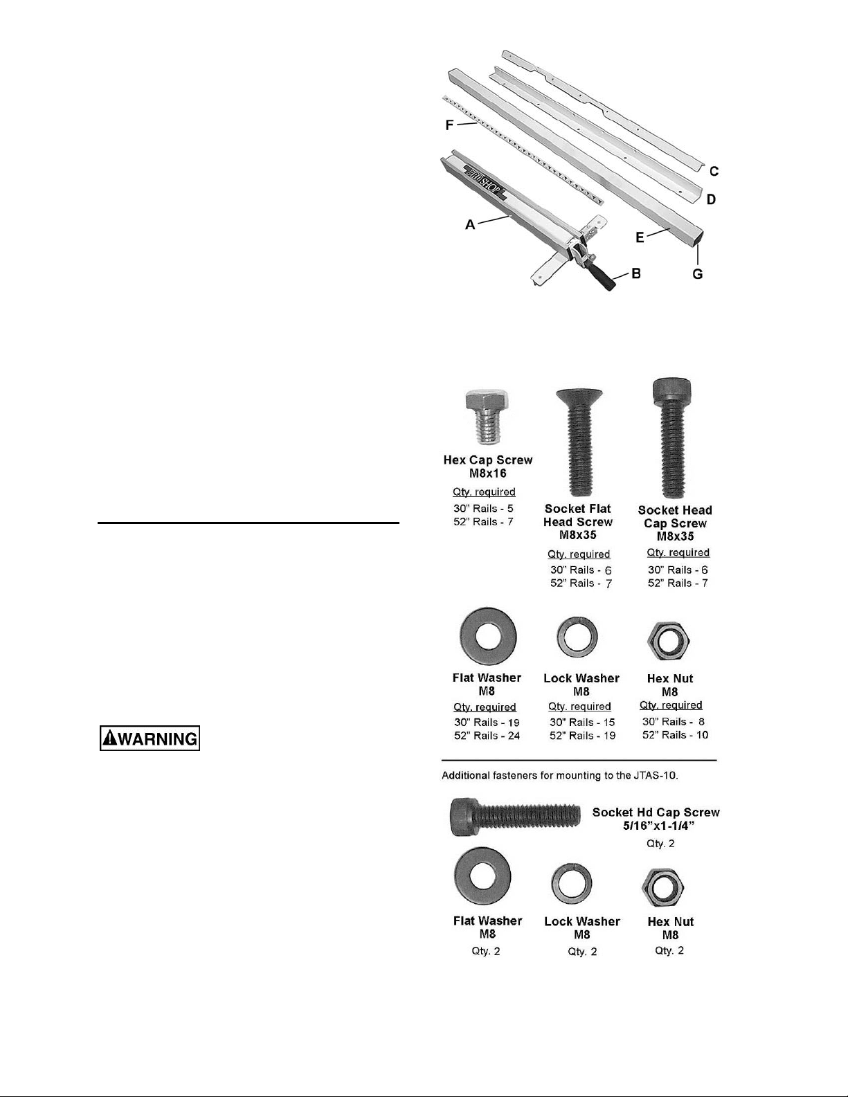
Contents of the Shipping Container
Figure 1
(shown in Figures 1 and 2)
1 ProShop Fence – A
1 Handle – B
1 Rear Rail – C
1 Front Rail – D
1 Guide Tube – E
1 Scale – F*
2 End Cover – G
1 Hardware Package (JPSR-RHP) – Figure 2
1 Owner's Manual
1 Warranty Card
* located inside Guide Tube (E)
Assembly and Adjustments
Tools requi red for assemb ly:
Hex wrenches – 4mm and 6mm
Open End Wrench, 13mm
Electric Drill with 3/16” and 5/16” drill bits (for
optional wood extens ion table only)
(4) C-Clamps, 4” to 6” (f or optional wood
extension table only)
Disconnect table saw from
power source before attempting any
assembly or adjustment.
Installing Rails
Refer to the exploded view on page 11 for any
clarification of part positions.
1. Place the rear rail against the back edge of
the table, making sure the notches in t he r ail
are properly ori ented. See Figure 3.
2. On the JPS-10TS table saw, insert four
M8x35 socket head c ap screws with M8 fl at
washers (plus M8 l ock washers on the two
inner screws).
Figure 2
(NOTE: These are not to scale)
4
Page 5

NOTE: On the JT AS-10 t able sa w, use 5/16
x 1-1/4 socket head cap screws f or the two
inner screws.
3. Secure the two outer screws with a flat
washer, lock washer and h ex nut behi nd the
lip of the saw table. Only finger tighten all
nuts and screws.
4. The rear rai l must be parallel to the tabl e top
to ensure proper f ence operation. Measure
the distance from the rail to the table
surface at several poi nts along the table. A
sliding c ombination square is handy f or thi s,
as shown in Figure 4. All measurements
should be the same. There is slight
adjustment in the rail holes to allow for
achieving par all elism with the table surface.
5. When the rear rail is parallel with the t able
surface, securely tighten all screws and nuts
along the length of the rail.
6. Place the front rail against the front edge of
the table, and insert four M 8x35 socket flat
head screws through the count ersunk holes
in the rail. Secure the two outer scre ws with
a flat washer, lock washer and hex nut
behind the li p of the table extensions. See
Figure 5.
NOTE: On the JPS- 10TS tabl e saw, the two
inner screws will thread into the table top
without further need of fasteners. On the
JTAS-10 tabl e saw, the t wo inner screws will
need flat washer, lock washer and hex nut
inside the lip of the table.
Figure 3
Figure 4
7. Mount the table saw control switch to the
threaded holes in t he bottom of the front rail
using the fast eners that came with the saw.
See Figure 6.
NOTE: If you are installing an optional wood
extension table, install it before mounting the
guide tube. See “Wood Extension Table
(Optional)”.
8. Remove the scale from inside the guide
tube, and place the black end cap on the
guide tube.
9. Ali gn the holes in t he guide tube with those
in the front r ail. The edge of the guide tube
near which the hol es are positi oned should
face toward the table saw. Insert seven
M8x16 hex cap screws, lock washers and
flat washers. See Figure 5. Finger tighten
only until all screws are inserted, then
tighten all screws. B e careful not to strip t he
holes while tightening.
Figure 5
Figure 6
5
Page 6

Wood Extension Table (Optional)
The optional wood extension table (including t he
optional r outer table) sits fl ush against the saw
table and along the inside of the rails. The
extension t able is not bolted t o the saw table; it
is bolted only to the rails. The extension table
and saw table m ust be aligned properl y so the
fence will slide smoothly from one to the other.
The wood extensi on table m ay be provided wit h
fasteners – do not use those with this JPSF
Fence and Rail system. Instead, use the
fasteners that ar e pr ovided with the JP S F Fence
and Rails.
1. Place the wood extension table upside
down on top of the tabl e saw.
IMPORTANT: If you are using a mobile
base under your saw, you may need t o shift
the placement of the legs from t hat shown in
the following pr oc edur e, so that the legs r est
properly upon the mobile base. Check this
before proc eeding.
2. Position t he leg bracket s at one end of t he
table, as shown in F igure 7. Hold a leg firmly
in place whil e driving the screws in u sing a
phillips bit i n a power drill.
NOTE: You may wish to f irst mark and predrill the holes. Pre-drill holes with a 3/16”
drill bit approx im ately 1/2” deep. Do not drill
through the table top or table frame!
Figure 7
3. Attach the other leg to the wood table in the
same manner.
4. Place the wood extension tabl e bet ween the
rails and up agai nst the saw table, leaving
the extension t able r aised just sli ghtl y above
the saw table. Cl amp the ext ension table to
the front and back rails as shown in Figure
8. Clamping pressure should be enough to
secure the table yet allow minor
adjustments.
5. Use a rubber mallet to tap the extension
table up flush against the saw table. Then
tap down the extension table at various
points along its edge where it meets the saw
table, until it is level with t he saw table. As
one part of the edge becom es level with the
table, tighten the clamp on that side. Then
move to t he other side and repeat , until the
full lengt h of the edge is l evel with the saw
table. Lay a straight edge across both
extension table and saw table to ensure
proper leveling.
6. When the wood extension tabl e is properly
aligned, dril l holes int o the wood table using
the holes in the rails as your guide. See
Figure 8.
Figure 8
6
Page 7

(You may wish to drill 3/32" pilot holes first. )
Drill 8mm (5/16”) holes i nto the front edge of
the table using the holes in the front rail as a
guide. Drill 8mm (5/16" ) holes i nto the back
edge of the table using the holes in the rear
rail as a guide.
7. Install M8 x 35 socket flat head screws
through the fr ont rail and secure eac h with a
flat washer, lock washer, and hex nut
behind the lip of t he wood table (Fi gure 9).
Finger tighten only.
8. Install M8 x 35 socket head cap screws and
flat washers in t he rear rail , and secure with
flat washer, l ock washer and hex nut behi nd
the lip of the wood tabl e (Figure 10). Finger
tighten only .
9. Re-check the table for alignment, make
further adjustments if necessary, then
tighten all screws and nuts.
10. Rotate the footpads on the legs until they
reach the floor, t hen tighten the hex nuts.
11. Proceed to step 6 on page 5 to assemble
the guide rail.
Figure 9
Figure 10
Installing the Fence
1. Thread the handle into the hole on the
fence.
2. Lift handle all the way up and place the
fence onto the rails. There are three
positions of the handle: T he up position for
mounting and removing the fence; middle
position f or sliding the fence al ong the rails;
and the down posi tion for locking t he fence
in place. Push the handle down fi rmly when
locking the fence in place.
Several adj ustment s are necessary befor e using
the fence for ripping wood; f ollow these step s in
the order in which they ar e pr esented.
Level with Saw Tabl e
3. Lock the fence on the guide rail.
4. View the f ence from the l eft or right side of
the saw. There should be a small space
between the table surface and the fence
bottom, t o prev ent the fence f rom dragging
on the saw table. This space should be
equal along the entire length of the fence,
as shown in Figure 11.
Figure 11
5. If this space is not equal, unlock the fence
and turn it over. Loosen the hex nut under
the adjustment foot (Figure 12) and rotate
the adjustment foot as needed to raise or
lower the rear of the fence. Ti ghten the hex
nut and re-position the fence to check the
spacing.
Figure 12
7
Page 8

6. If the front of the fence needs adjusting,
rotate the two nylon adjustment screws an
equal amount (see Figur e 13) .
7. Continue these two adjustment methods
until the fence- to-table spacing is correct.
Square to Table
8. Place a square on the table and agai nst the
side of the fence, as shown in Figure 13.
Lock the fence down with the handle. The
fence should be 90° to the t able.
9. If the fence is not 90° to the table, unlock
the fence and rotate one of the two nylon
adjustment screws (clockwise will raise that
side of the fence assembly, counterclockwise will lower). Lock the fence and
check the adjustment again. Continue to
adjust as needed.
Parallel to Miter Slot
10. Check parallelism of the fence by placing
the side of the f ence fl ush with the mit er sl ot
in the table. Lock the fence down with the
handle.
11. If the side of the fence is not parallel with
the miter slot, unlock t he fence and lift it off
the guide rail. Adjust one of the two set
screws (Figur e 14) until the fenc e is parall el
to the miter slot along its enti re length when
in locked position.
NOTE: You may need to re-adj ust the cl ampi ng
pressure aft er aligning the fence.
Clamping Pressure
The fence has been adjusted at the factory to
lock securel y when the handle is pushed down.
If adjustm ent is needed, unlock the fence and lift
if off the guide rail. Adjust the two set screws
(Figure 14) equally until the fence is held
securely when the lock handle is pushed down.
Figure 13
Figure 14
Attaching the Scale
Saw must be disconnected
from power source.
Important: The fence must be square to the
table and parallel to the miter slot before
attaching the scale. Follow all preceding
instructions before continuing.
1. Install a blade on the saw, and raise the
blade above the tabl e surface. Lift the blade
guard and the anti- kickback pawl out of the
way.
2. Slide the fence until it just contacts the
cutting tips of t he blade (Figure 15). Do not
force the fence into the blade.
Figure 15
8
Page 9

3. Center the cursor on the screws to allow
future adjustment on both sides of the
cursor line. See Figure 16. Draw a line on
the guide tube even with the cursor line.
4. Remove the f ence, and clean the guide tube
surface with alcohol. Peel off some of the
scale backing, and align the zero point of
the scale with your mark on the gui de tube.
See Figure 17. Position the scale far
enough from t he edge so that i t can be read
easily through the cursor lens. Continue to
peel the backi ng and apply the scale, while
keeping the scale as straight as possible
along the guide tube.
5. Connect the saw to po wer and make a test
cut. Carefully measure the width of the cut
board and adjust the f ence cursor to match
this measurement.
NOTE: Cursor position should be re-verified
after each blade change. Always make test cut s
to verify se ttin g s.
Figure 16
Replacement Parts
Figure 17
Replacement par ts are li sted on the f ollowing page s. To order parts or reac h our servi ce depar tm ent, call
1-800-274-6848 Monday through Friday (see our website for business hours, www.powermatic.com).
Having the Model Number and Serial Number of your mac hine available when you cal l will allow us to
serve you quickly and accurately.
9
Page 10

52” & 30” Pro Shop Rail Set
10
Page 11

Parts List for the 52” & 30” Pro Shop Rail Set
Index No. Part No . Description Size Qty
................. 708484 ....................JPSR-52: 52” Pro Shop Rail Set ..............................................................
................. 708483 ....................JPSR-30: 30” Pro Shop Rail Set ..............................................................
1 ............... JPSR52 -101 ............52” Guide Tub e ..................................................................................... 1
................. JPSR30 -101 ............30” Guide Tub e ..................................................................................... 1
2 ............... JPSR52 -102 ............52” Front Rail......................................................................................... 1
................. JPSR30 -102 ............30” Front Rail......................................................................................... 1
3 ............... JPSR52 -103 ............52” Rear Rail ......................................................................................... 1
................. JPSR30 -103 ............30” Rear Rail ......................................................................................... 1
4 ............... JPSR30 -104 ............End Cover ............................................................................................. 2
5 ............... TS-1490021 .............Hex Cap Scr e w ..................................................M8x16 ........................ 7
6 ............... TS-2361081 .............Lock Was h e r ......................................................M8 ............................ 21
7 ............... JPSR30 -107 ............Flat Head Socket Screw .....................................M8x35 ........................ 7
8 ............... TS-1540061 .............Hex Nut ..............................................................M8 ............................ 12
9 ............... TS-1504071 .............Socket Head Cap Screw .....................................M8x35 ........................ 7
10 ............. JPSR52-110 ............52” Scale ............................................................................................... 1
................. JPSR30 -110 ............30” Scale ............................................................................................... 1
11 ............. TS-1550061 .............Flat Was he r ........................................................M8 ............................ 2 6
12 ............. TS-0208071 .............Socket Head Cap Screw (for JTAS-10 only) ........5/16”-18x1-1/4” ........... 2
................. JPSR-RHP ...............Rail Hardware Package (not shown) ............ ...........................................
11
Page 12

Parts List for the JPSF-1 Pro Shop Fence
Index No. Part No . Description Size Qty
................. 708482 ....................JPSF-1 Pro Shop Fence Assembly ..........................................................
1 ............... JPSF1-101A ............Side Plate End Cover ............................................................................ 4
2 ............... JPSF1-102A ............Side Plate .............................................................................................. 2
3 ............... JPSF1-10 3 ...............Square Bolt ........................................................M8x20 ........................ 6
4 ............... TS-1550061 .............Flat Washe r ........................................................M8 .............................. 6
5 ............... TS-1540061 .............Hex Nut ..............................................................M8 .............................. 6
6 ............... TS-1534032 .............Pan Head Screw ................................................M6x10 ........................ 2
7 ............... TS-1550041 .............Flat Washe r ........................................................M6 .............................. 2
8 ............... JPSF1-10 8 ...............Cursor ................................................................................................... 1
9 ............... JPSF1-10 9 ...............Adjustment Screw.................................................................................. 2
10 ............. JPSF1-110 ...............Fence Body ........................................................................................... 1
11 ............. JPSF1-111 ...............Slide Hold Plate ..................................................................................... 1
12 ............. JPSF1-112 ...............Pad ....................................................................................................... 2
13 ............. TS-1491081 .............Hex Cap Screw ..................................................M1 0 x50 ...................... 1
14 ............. TS-1482101 .............Hex Cap Screw ..................................................M6 x50 ........................ 1
15 ............. JPSF1-115 ...............Lock Plate ............................................................................................. 1
16 ............. TS-2246101 .............Flat Head Screw .................................................M6x10 ........................ 2
17 ............. JPSF1-117 ...............Lock Cam .............................................................................................. 1
18 ............. JPSF1-118 ...............Handle................................................................................................... 1
19 ............. TS-1541041 .............Nylon Insert Lock Nut .........................................M10 ............................ 1
20 ............. TS-1524011 .............Set Screw ...........................................................M8x8 .......................... 2
21 ............. JPSF1-121 ...............Adjustment Foot .................................................................................... 1
22 ............. TS-1540041 .............Hex Nut ..............................................................M6 .............................. 1
23 ............. JPSF1-123 ...............Stop Pad ............................................................................................... 1
24 ............. TS-1541021 .............Nylon Insert Lock Nut .........................................M6 .............................. 1
25 ............. JPSF1-25 .................JET Logo (not shown)............................................................................ 1
26 ............. JPSF1-26 .................ProShop Label (not shown) ................................................................... 1
12
 Loading...