

Page 1
This .pdf document is bookmarked
Operating Instructions and Parts Manual
12-inch Jointer-Plane r
Models JJP-12, JJP-12H H
JET
427 New Sanford Road
LaVergne, Tennessee 37086 Part No. M-708475
Ph.: 800-274-6848 Revision D 10/2014
www.jettools.com Copyright © 2014 JET
Page 2

1.0 Warranty and service
JET warrants every product it sells against manufacturers’ defects. If one of our tools needs service or repair, please
contact Technical Service by calling 1-800-274-6846, 8AM to 5PM CST, Monday through Friday.
Warranty Period
The general warranty lasts for the time period specified in the literature included with your product or on the official
JET branded website.
• JET products carry a limited warranty which varies in duration based upon the product. (See chart below)
• Accessories carry a limited warranty of one year from the date of receipt.
• Consumable items are defined as expendable parts or accessories expected to become inoperable within a
reasonable amount of use and are covered by a 90 day limited warranty against manufacturer’s defects.
Who is Covered
This warranty covers only the initial purchaser of the product from the date of delivery.
What is Co vered
This warranty covers any defects in workmanship or materials subject to the limitations stated below. This warranty
does not cover failures due directly or indirectly to misuse, abuse, negligence or accidents, normal wear-and-tear,
improper repair, alterations or lack of maintenance. JET woodworking machinery is designed to be used with Wood.
Use of these mac hines in the proces sing of metal, pla st ics, or ot her mat er ials may void the warranty. T he excep tio ns
are acrylics and other natural items that are made specifically for wood turning.
Warranty Limitations
Woodworking products with a Five Year Warranty that are used for commercial or industrial purposes default to a
Two Year Warranty. Please contact Technical Service at 1-800-274-6846 for further clarification.
How to Get Technical Support
Please contact Technical Service by calling 1-800-274-6846. Please note that you will be asked to provide proof
of initia l p u rch a s e whe n calling. If a product requires further inspection, the Technical Service representative will
explain and assist with any additional action needed. JET has Authorized Service Centers located throughout the
United States. For the name of an Authorized Service Center in your area call 1-800-274-6846 or use the Service
Center Locator on the JET website.
More Informa tion
JET is constantly adding new products. For complete, up-to-date product information, check with your local distributor
or visit the JET website.
How S tate Law Applies
This warranty gives you specific legal rights, subject to applicable state law.
Limitations on This Warranty
JET LIMITS ALL IMPLIED WARRANTIES TO THE PERIOD OF THE LIMITED WARRANTY FOR EACH PRODUCT.
EXCEPT AS STATED HEREIN, ANY IMPLIED WARRANTIES OF MERCHANTABILITY AND FITNESS FOR A
PARTICULAR PURPOSE ARE EXCLUDED. SOME STATES DO NOT ALLOW LIMITATIONS ON HOW LONG AN
IMPLIED WARRANTY LASTS, SO THE ABOVE LIMITATION MAY NOT APPLY TO YOU.
JET SHALL IN NO EVENT BE LIABLE FOR DEATH, INJURIES TO PERSONS OR PROPERTY, OR FOR
INCIDENTAL, CONTINGENT, SPECIAL, OR CONSEQUENTIAL DAMAGES ARISING FROM THE USE OF OUR
PRODUCTS. SOME STATES DO NOT ALLOW THE EXCLUSION OR LIMITATION OF INCIDENTAL OR
CONSEQUENTIAL DAMAGES, SO THE ABOVE LIMITATION OR EXCLUSION MAY NOT APPLY TO YOU.
JET sells through distributors only. The specifications listed in JET printed materials and on official JET website are
given as general information and are not binding. JET reserves the right to effect at any time, without prior notice,
those alterations to parts, fittings, and accessory equipment which they may deem necessary for any reason
whatsoever. JET
Product Listing with Warranty Period
90 Days – Parts; Consumable items; Light-Duty Air Tools
1 Year – Motors; Machine Accessories; Heavy-Duty Air Tools; Pro-Duty Air Tools
2 Year – Metalworking Machinery; Electric Hoists, Electric Hoist Accessories; Woodworking Machinery used
for industrial or commercial purposes
5 Year – Woodworking Machinery
Limited Lifetime – JET Parallel clamps; VOLT Series Electric Hoists; Manual Hoists; Manual Hoist
Accessories; Shop Tools; Warehouse & Dock products; Hand Tools
NOTE: JET is a division of JPW Industries, Inc. References in this document to JET also apply to JPW Industries,
Inc., or any of its successors in interest to the JET brand.
®
branded products are not sold in Canada by JPW Industries, Inc.
2
Page 3

2.0 Table of contents
Section Page
1.0 Warranty and service ..................................................................................................................................... 2
2.0 Table of contents ............................................................................................................................................ 3
3.0 Safety warnings .............................................................................................................................................. 4
4.0 Specifications ................................................................................................................................................. 6
5.0 Features and terminology .............................................................................................................................. 7
6.0 Receiving ....................................................................................................................................................... 7
7.0 Unpacking ...................................................................................................................................................... 7
8.0 Electrical connection ...................................................................................................................................... 7
9.0 Operating controls .......................................................................................................................................... 8
9.1 Jointer to Planer setup ............................................................................................................................... 8
9.2 Planer to Jointer setup ............................................................................................................................... 8
9.3 Control switch ............................................................................................................................................. 9
9.4 Planer controls and adjustments ................................................................................................................ 9
9.5 Jointer controls and adjustments ................................................................................................................ 9
10.0 Adjustments ............................................................................................................................................... 11
10.1 Table and knife adjustments .................................................................................................................. 11
10.2 Coplanar alignment ................................................................................................................................ 11
10.3 Setting cutterhead knives (straight knives only) ..................................................................................... 13
10.4 Replacing cutterhead knives (straight knives only) ................................................................................ 14
10.5 Replacing or rotating knife inserts (helical cutterhead only) ................................................................... 14
10.6 Jointer table lock handle adjustment ...................................................................................................... 15
10.7 Belt replacement .................................................................................................................................... 15
10.8 Feed roller height adjustment ................................................................................................................. 16
10.9 Feed roller pressure adjustment ............................................................................................................. 17
10.10 Planer table adjustment ........................................................................................................................ 17
11.0 Basic operations ......................................................................................................................................... 18
11.1 Dust collection ........................................................................................................................................ 18
11.2 Initial startup ........................................................................................................................................... 18
11.3 Changing mode of operation .................................................................................................................. 18
11.4 Jointer operations ................................................................................................................................... 18
11.5 Planer operations ................................................................................................................................... 20
12.0 Maintenance ............................................................................................................................................... 22
12.1 Blade care .............................................................................................................................................. 22
12.2 Sharpening knives (straight knives only) ................................................................................................ 22
13.0 Lubrication .................................................................................................................................................. 22
14.0 Troubleshooting the JJP-12,JJP-12HH ...................................................................................................... 23
14.1 Performance troubleshooting – Jointer .................................................................................................. 23
14.2 Performance troubleshooting – Planer ................................................................................................... 24
14.3 Mechanical troubleshooting – Planer/Jointer ......................................................................................... 25
15.0 Replacement parts ..................................................................................................................................... 26
15.1 Parts List for JJP-12, JJP-12HH ............................................................................................................. 26
15.2 Infeed Table Assembly – Exploded View ............................................................................................... 31
15.3 Outfeed Table Assembly – Exploded View ............................................................................................ 32
15.4 Cutterblock Assembly – Exploded View ................................................................................................. 33
15.5 Base Assembly – Exploded View ........................................................................................................... 34
15.6 Motor Assembly – Exploded View .......................................................................................................... 35
15.7 Planer Table Assembly – Exploded View ............................................................................................... 36
15.8 Fence Assembly – Exploded View ......................................................................................................... 37
16.0 Electrical connection for JJP-12, JJP-12HH .............................................................................................. 38
17.0 Optional accessories .................................................................................................................................. 39
3
Page 4

3.0 Safety warnings
1. Read and understand the entire owner's manual before attempting assembly or operation.
2. Read and understand the warnings posted on the machine and in this manual. Failure to comply with all of
these warnings may cause serious injury.
3. Replace the warning labels if they become obscured or removed.
4. This woodworking Jointer-Planer is designed and intended for use by properly trained and experienced
personnel only. If you are not familiar with the proper and safe operation of a woodworking jointer or
planer, do not use until proper training and knowledge have been obtained.
5. Do not use this machine for other than it s intended use. If used for ot her pu rposes, JET d isclaim s any rea l
or implied warranty and holds itself harmless from any injury that may result from that use.
6. Always wear approved safety glasses/face shield while using this woodworking jointer-planer. NOTE:
Everyday eyeglasses only have impact resistant lenses; they are not safety glasses.
7. Before operating this woodworking jointer-planer, remove tie, rings, watches and other jewelry, and roll
sleeves up past the elbows. D o not wear loose clothing. C onfine long hair. Non-slip footw ear or anti-skid
floor strips are recommended. Do not wear gloves.
8. Wear ear protectors (plugs or muffs) during extended periods of operation.
9. Some dust created by power sanding, sawing, grinding, drilling and other construction activities contain
chemicals known to cause cancer, birth defects or other reproductive harm. Some examples of these
chemicals are:
• Lead from lead based paint.
• Crystalline silica from bricks, cement and oth er masonry products.
• Arsenic and chromium from chemically treated lumber.
Your risk of exposure varies, depending on how often you do this type of work. To reduce your exposure to
these chemicals, work in a well-ventilated area and work with approved safety equipment, such as face or
dust masks that are specifically designed to filter out microscopic particles.
10. Do not operate this machine while tired or under the influence of drugs, alcohol or any medication.
11. Make certain the switch is in the OFF position before connecting the machine to the power source.
12. Make certain the machine is properly grounded.
13. Make all machine adjustments or maintenance with the machine unplugged from the power source.
14. Remove adjusting keys and wrenches. Form a habit of checking to see that keys and adj usting wrenches
are removed from the machine before turning it on.
15. Keep safety guards in place at all times when the machine is in use. If removed for maintenance purposes,
use extreme caution and replace the guards immediately.
16. Make sure the jointer-planer is firmly secured to the floor or bench before use.
17. Check damaged parts. Before further use of the machine, a guard or other part that is damaged should be
carefully checked to determine that it will operate properly and perform its intended function. Check for
alignment of moving parts, binding of m oving parts, breakage of parts, mounting a nd any other conditions
that may affect its operation. A guard or other part that is damaged should be properly repaired or
replaced.
18. Provide for adequate space surrounding work area and non-glare, overhead lighting.
19. Keep the floor around the machine clean and free of scrap material, oil and grease.
20. Keep visitors a safe distance from the work area. Keep children away.
21. Make your workshop child proof with padlocks, master switches or by removing starter keys.
4
Page 5

22. Give your work undivided attention. Looking around, carrying on a conversation and “horse-play” are
careless acts that can result in serious injury.
23. Maintain a balanced stance at all times so that you do not fall or lean against the cutterhead or ot her
moving parts. Do not overreach or use excessive force to perform any machine operation.
24. Use the right tool at the correct speed and feed rate. Do not force a tool or attachment to do a job for which
it was not designed. The right tool will do the job better and more safely.
25. Use recommended accessories; improper accessories may be hazardous.
26. Maintain tools with care. Keep cutters sharp and clean for the best and safest performance. Follow
instructions for lubricating, and changing accessories.
27. Make sure the workpiece is sec urely attached or clamped to the table. Never use your hand to hold t he
workpiece.
28. Turn off the machine before cleani ng. Use a brush or com pressed air to remove chips or debris — do not
use your hands.
29. Do not stand on the machine. Serious injury could occur if the machine tips over.
30. Never leave the machine running unattended. Turn the power off and do not leave the machine until the
cutterhead comes to a complete stop.
31. Before turning on machine, remove all extra equipment such as keys, wrenches, scrap, stock, and cleaning
rags away from the machine.
Jointer operation
32. Always use a hold-down or push block when surfacing stock less than 12" inches long, or 3 inches wide, or
3 inches thick.
33. Do not perform jointing operations on material shorter than 8", n a rrower than 3/4" or less than 1/4" thick.
34. The hands must never be closer than 3 i nches to the cutterhead (see
Fi gur e at right).
35. Never app ly pressure to stock directly over the cutterhead. Thi s may
result in the stock tipping into the cutterhead along with the operator's
fingers. Position hands away f rom extreme ends of stock, and p ush
through with a smooth, even motion. Never back workpiece toward
the infeed table.
36. To avoid kickback, the grain must run in the same direction you are cutting. Before attempting to joint or
plane, each workpiece must be carefully examined for stock condition and grain orientation.
37. When working with a swirl grain wood or burls, making it necessary to plane against the grain, use a lesser
depth of cut and a slow rate of feed.
38. Move the hands in an alternate motion from back to front as the work continues through the cut. Never
pass the hands directly over the cutter knife. As one hand approaches the knives, remove it from the stock
in an arc motion and place it back on the stock in a position beyond the cutter knife.
39. At all times hold the stock firmly against the table and fence.
Planer ope r a t i on
40. Keep hands outside the machine. NEVER reach under the guards to try to clear stock that stops
feeding. Do not cl ear chi ps and s awdust wit h hands; use a bru sh. Do not have any part of t he hands
under that part of the board t hat is over the table when starting a cut; the inf eed roll will engage the
board and forc e it down against t he table causing a pinching acti on.
41. Check stock conditi on. Do not pl ane boards with l oose knots or with nai ls or any f orei gn materi al on
its surfac e. Knife impact on t hese objects can cau se the kniv es to be pulled out and cause them t o
shatter against the chipbreaker or pressure bar. Twisted, warped, or in wind stock should first be
jointed on one surface before attempting to plane a parall el surf ac e on the planer. Serious stock flaws
cannot be removed by use of a planer alone.
42. T o avoid kickbac ks, use this machine f or single board surfaci ng only. Never make cuts deeper t han
1/8 inch (3mm).
5
Page 6

Familiariz e y our self with the following safety noti c es used in this manual:
This means that if precautions are not heeded, it may result in minor injury and/or
possible machine damage.
This means that if prec autions are not heede d, i t may result i n serious i njur y or possi bly
even death.
4.0 Specifications
Model number .......................................................................... JJP-12 ................................................... JJP-12HH
Stock number .......................................................................... 708475 ....................................................... 708476
Cutterhead speed (RPM) ............................................................ 5500 ........................................................... 5500
Cutterhead diameter (in.) ............................................................ 2-3/4 ........................................................... 2-3/4
Number of knives .............................................................................. 3 .................................. 56 four-sided inserts
Knife size (LxWxT)(in.) ............................................... 12 x 1-3/5 x 1/8 ...................................... 0.59 x 0.59 x 0.10
Dust port outside diameter (in.) ......................................................... 4 ................................................................. 4
Dust collection minimum CFM ...................................................... 400 ............................................................. 400
Jointer table size (LxW/in.) ...................................................... 55 x 12 ....................................................... 55 x 12
Table height from floor (in.) ....................................................... 33-1/2 ......................................................... 33-1/2
Maximum stock removal (in.) ......................................................... 1/8 .............................................................. 1/8
Fence size (L xH/in.) .................................................................. 43 x 6 ......................................................... 43 x 6
Fence tilt .......................................................................... 90° to 45° R ................................................ 90° to 45° R
Fence positive stop ....................................................... 90° and 45°R .............................................. 90° and 45°R
Planer table size (LxW/in.) ................................................ 21-1/4 x 12 ................................................. 21-1/4 x 12
Full width cutting depth (in.) ........................................................... 1/8 ..................................... See Table 1 below
Maximum workpiece thickness (in.) ........................................... 8 -3/4 ........................................................... 8-3/4
Maximum depth of cut (in.) ........................................................... 5/32 ..................................... See Table 1 below
Minimum length of workpiece (in.) .................................................... 6 ................................................................. 6
Feed rate .................................................................................. 20 fpm ........................................................ 12 fpm
Table movement per one handwheel revolution ......................... 5/32” ........................................................... 5/32”
Motor, TEFC ................................ 3HP, 1PH, 230V only, 60Hz, 12.5A ........... 3HP, 1PH, 230V only, 60Hz, 12.5A
Switch ...............................................magnetic switch with limit switch ................ magnetic switch with limit switch
Power cord (plug not included) ............................. 14AWG 300V, 8 ft. ..................................... 14AWG 300V, 8 ft.
Overall Dimensions (LxWxH/in.) ......................... 55 x 29-1/2 x 39-2/5 ................................... 55 x 29-1/2 x 39-2/5
Stand Footprint (LxW/in.) .................................................. 22 x 19-1/2 ................................................. 22 x 19-1/2
Net weight (lbs.) ............................................................................ 500 ............................................................. 500
Full Width Cutting Depths for Helical Cutterheads During Planing
Very dense and/or very tight grained lumber (e.g., Rock
Maple, Purpleheart, Ipe)
Dense and/or tight grained lumber (e.g., Oak, Ash, Walnut) No more than 3/32” per full width cut per pass
Soft woods (e.g., Douglas Fir or White Pine) No more than 1/8” per full width cut per pass
No more than 1/16” per full width cut per pass
Table 1
The specifications in this manual are given as general inf ormation and ar e not binding. JET reserves the right to
effect, at any time and without prior notice, changes or alterations to parts, fittings, and accessory equipment deemed
necessary for any r eason whatsoever.
Read and understand the entire contents of this manual before attempting
assembly or operat io n! Failure to comply may cause serious injury!
6
Page 7
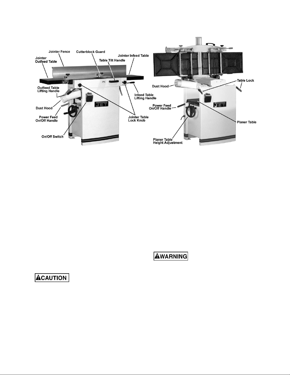
5.0 Features and terminology
Figure 1 – Featur es and Terminology
6.0 Receiving
Carefully unpack the machine and any loose
items from the wood crate and inspect for
damage. Any damage should be reported
immediately to your distributor and shipping
agent. Before proceeding further, read your
manual thoroughly to familiarize yourself with
proper assembly, maintenance and safety
procedures.
Remove the screws that hol d the machi ne to the
shipping skid. Remove the protective coating
from the table, bed rolls, feed rolls, cutterhead
and loose items packed wit h the machine. This
coating may be removed with a soft cloth
moistened with kerosene. Do not use acetone,
gasoline or l acquer thinner f or this purpose. Do
not use solvents on pl astic parts.
Use care when cleaning the
cutterhead ; th e kni ves are very sharp.
7.0 Unpacking
1. Remove all contents from the shipping
carton. Do not discard the car ton or packi ng
material until the machine is set up and
running satisfactorily.
2. Inspect the contents for shipping damage.
Report damage, if any, to your distributor.
Tools Required for Assembly
1 Accurate Straight Edge (approximately 2 ft)
1 Cross-point Screwdriver
1 4mm Hex Wrench (included)
1 5mm Hex Wrench
1 6mm Hex Wrench (included)
1 10mm Box Wrench
1 13mm Box Wrench
Note: Use of sockets and ratchets will speed
assembly time but are not required.
8.0 Electrical connection
All electrical connections
must be done by a qualified
electrician . All adjustments or repai rs must
be done with the machine di sconnect ed from
the power source, unplugged. Failure to
comply may result in serious injury!
The Model JJ P-12 and JJ P-12HH Joi nt er-Planer
is rated at 230V. This machine is not supplied
with a plug. Use a pl ug and outlet rated at least
30 amps. The circuit for the machine should also
be protected by at least a 30 amp cir c uit breaker
or fuse.
Make sure the cutterhead rotates in the
proper direction. If it does not, disconnect
machine fr om power supply and r ev erse two of
the phase wires on the supply input.
7
Page 8
9.0 Operating controls
Disconnect machine from
power source b efore making any adjust ments.
Failure to compl y may cause seri ou s injury.
Cutterhead knives are
dangerousl y sharp. Use extreme caution when
working around them. Failure to comply may
cause serious inj ury.
9.1 Jointer to Planer setup
To change the machine c onf iguration from jointer
to planer (refer to Fi gur e 2):
1. Release both cabinet table locks (A) by rotat-
ing the handles toward the operator, then
pulling away from the machine.
2. Raise the table (C) using the handle (B).
Table is heavy. Use care when
raising. F ailure to compl y may
cause serious inj ury.
When raised, the table should be in the
vertical position as shown in C, Fig. 3. The
latch (E, Fig. 3) should be engaged,
preventing the table from an accidental
forward fall.
3. Position the dust chute (D,H Fig. 3) to the
right. Use ex treme care t o av oid contact with
cutterhead knives.
Figure 2
Note: The planer table may need to be
lowered to all ow clearance needed to position
the dust chute.
9.2 Planer to Jointer setup
Refer to Figure 3:
To change the m achine configurati on from planer
to jointer:
1. Pull the release knob (F) and reposition the
dust chute (D, G) to the left. It should be
positioned as shown i n D, Fi g. 2.
Table is heavy. Use care when
lowering. Failure to comply
may cause serious injury.
2. Release the latch (E) and bring the table
forward using the tilt handle (B). It should be
positioned as shown i n C, Fi g. 2.
3. Lock the table (C) by pushing the lock
handles (A) in toward the machine and
rotating down (away from the operator).
Figure 3
8
Page 9
9.3 Control switch
Once a properly rated plug is connected, plug
power cord int o outlet. Press the green on but ton
(A, Fig. 4) to start. Press the red off button
(B, Fig. 4) to stop.
9.4 Planer controls and adjustments
Refer to Figure 5:
Power Feed
Placing the planer power feed handle (D) in the up
position turns the planer power feed on (see
arrow). Placing the handle in the down position
turns the power feed off.
Table Lock
Turn the table lock (E ) clock wise to l ock the height
adjustment handwheel (F) and secure the planer
table (C) in its selected position. Turn the table
lock (E) counterclockwise to release and permit
table adjustment.
Table Height Adjustment
The planer tabl e height is set as follows:
Figure 4
1. Unlock the table lock (E).
2. Rotate the height adjustment handwheel (F)
clockwise to raise the planer table (C),
countercl oc k wise to lower.
3. Lock the table lock (E).
Each revoluti on of the handwheel (F) results in a
5/32" up or down movement of the table (C). A
scale on the handwheel column indicates the
amount of handwheel rotation. A pointer (B)
indicates the table position relative to the
cutterhead on t he scale (A) located on the side of
the cabinet.
9.5 Jointer controls and adjustments
Refer to Figure 6:
Outfeed Table Height Adjustment
Lock knob (C) and lifting handle (B) control the
height adjustment of the outfeed table (A).The
outfeed tabl e i s ini tiall y adj usted at t he f actor y and
should not be repositioned except during certain
adjustments. These are described in sect. 10.1,
Table and Knife Adjust ments.
Figure 5
Infeed Table Height Adjustment
Lock knob (D) and lifting handle (E) control the
height adjustment of the infeed table (F).
To adjust:
1. Loosen lock knob (D).
Figure 6
9
Page 10
2. Raise the lif ting handle (E) to raise the inf eed
table for a shallow depth of cut. Lower the
handle for a deeper c ut.
3. Tighten the lock knob (D).
The infeed t able lifting handle in t he fully lowered
position resul ts in a depth of cut of 5/32".
Note: A depth of cut of 1/16" or less is recom-
mended.
Cutterhead Guard
Properly posi tioned, the cutterhead guard (H, Fig.
7) should rest against t he fence (A, Fig. 7).
Fence Movement
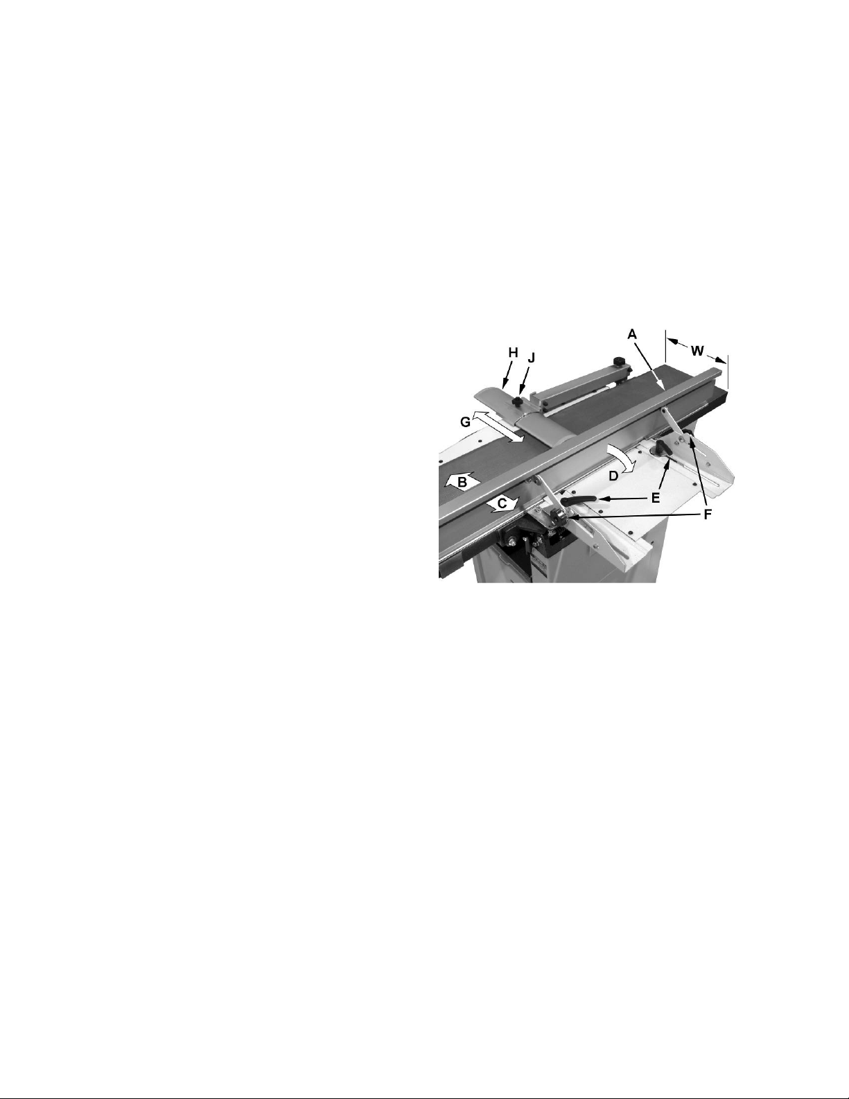
Refer to Figure 7:
The fence (A) can be moved forward (B) or
backward (C) acro ss the width (W ) of the tabl e. It
also tilt s up to 45 degrees backwards (D).
Loosen the lock knob (J), slide the guard into
position, then ti ghten the lock knob.
When edge jointing, the fence assembly should
periodically be moved to different positions to
distribute wear on the cutterhead knives.
To slide fence f or ward or back ward:
1. If necessary, loosen the c utterhead guard (H)
to permit the fence assembly to move freely
without being c onstr ained by the guard.
2. Loosen two fence assembly locking
handles (E).
3. M ov e the enti re fence assembl y t o the desired
position; then re- tighten the handles (E).
4. Readjust and secure the cutterhead guard.
To tilt fence back ward:
The fence (A) can be tilted backward (D) up to 45°
(that is, for a total included angle of 135° from
table surface) as follows:
1. Loosen locking handles (F).
2. Tilt the fence back (A , C) to t he desired a ngle
up to 135 degrees. Or you can place your
beveled reference piece on the table and
against the f ence, adj usting t he f ence unt i l t he
angle of the f ence matches the bev el of your
gauge piece.
3. Tighten the locking handles (F).
4. Readjust and secure the cutterhead guard.
Figure 7
10
Page 11
10.0 Adjustments
10.1 Table and knife adjustments
For accurat e jointi ng, at least thr ee thi ngs m ust be
true:
1. Infeed and outfeed tables must be coplanar.
2. Knives or knife inserts must be set in the
cutterhead so that the highest point of their ar c
is level with the outfeed table.
3. On the standard cutterhead, knives must be
parallel with the outfeed table across the
entire length of the knives.
These alignments are explained below.
Disconnect machine from
power source b efore making any adjust ments.
Failure to compl y may cause seri ou s injury.
10.2 Coplanar alignment
Definit io n of c op la na r
When the infeed tabl e is set to the same level as
the outfeed tabl e and all points on the t ables lie in
the same plane, thus forming a "perfect" flat
surface, the t ables are said to be coplanar.
Figure 8
For optim um perform ance of the j ointer , the i nfeed
and outfeed tables must be coplanar. If they are
not, the fi nished workpiec e may have a slight taper
or twist across its jointed width or length.
Determining if t abl es are coplanar
The tables hav e been set coplanar at the factory,
but they should be double-checked by the
operator. Also, as the machine undergoes use, the
tables should be checked occasionally and
adjusted if necessary.
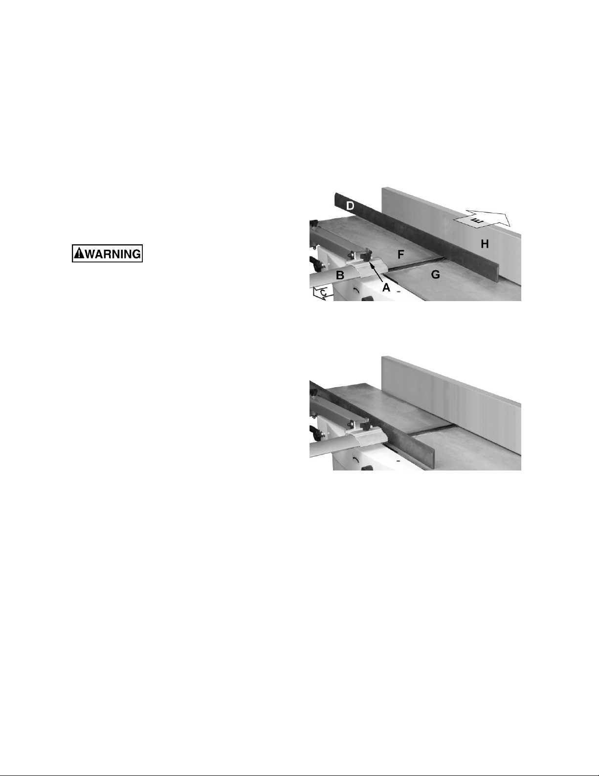
The procedure described below uses a steel
straight edge to set the tables, which should be
accurate enough for most purposes.
Important: The t ables must be locked i n position
when performing the following test.
Refer to Figures 8 and 9:
1. Disconnect jointer from power source.
2. Loosen the lock knob (A) and slide the
cutterhead guard ( B , C) to clear the table.
3. Slide the fence assembly back (H, E) as far as
it will go, or remove it from the machine
entirely.
4. Rotate the cutterhead to avoid knife
interference.
Figure 9
5. Place a st raight edge (D) ac ross the back of the
outfeed table (F ) and ext ending over t he infeed
table (G). Note the position of the infeed table
(G). Note the position of the straight edge in
Figure 8 with respect to the fence (H).
6. Raise the infeed table (G) until it contacts the
straight edge (D).
The straight edge should lie level across both
tables. Move the straight edge to the front of the
outfeed tabl e as shown i n Fi gure 9 and perf orm t he
same test .
If the straight edge does not lie level, the front or
back of one of the tabl es must be adjusted t o make
the tables coplanar. Proceed as described in
Performing t he c oplanar alignm ent (following page).
11
Page 12
Performing the coplanar alignment
If alignment is required as determined in the
previous section, proceed as follows:
Disconnect machine from
power source before making
any adjustmen ts. Failure to comply may cause
serious injury.
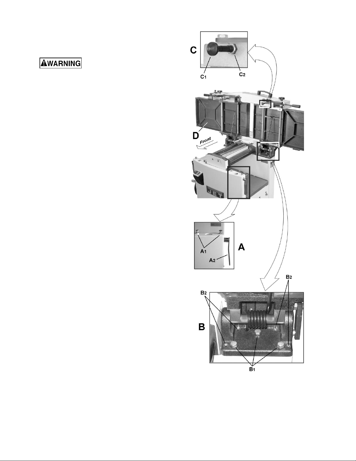
1. Disconnect power from machine.
2. Unlock both cabinet lock handles (A2,Fig. 10).
3. Raise the table (D) fully upright.
Adjustment is performed by means of four
setscrews (B
) that adjust the t abl e pitch and ti lt at
2
the back (towards the fence) and two hex cap
screws (A
) that adjust the table toward the fr ont.
1
Adjustment c an consist of a front adjust ment, rear
adjustment or (more probable) a combination of
both.
Rear adjustment
Tools requir ed – 13mm wrench, 4mm hex wrench
1. With a 13mm wrench, loosen three hex cap
screws (B
).
1
2. Using a 4mm hex wrench, make very slight
adjustments of 1/8 to 1/4 turns to four
setscrews (B2) as required.
A clockwise turn will raise the table; a
counterclockwise turn will lower the table.
Adjusting the two right setscrews will have
greatest adjustm ent impact t o the table's ri ght
side; adjusting the two left setscrews will have
greatest adjustment impact to the table's left
side.
3. When adjustm ent is complete, tighten t he hex
cap screws (B
).
1
Front adjustment
Tools requir ed – two 13mm wrenches
1. Hold the hex cap screws (A
) in place with one
1
wrench while using the other to loosen the
locking hex nut s.
2. Adjust the screws (A
) slightly from 1/8 to 1/4
1
turn.
A countercl ockwise turn will raise the table; a
clockwise turn will lower the table. Adjusting
the right screw will have greatest adjustment
impact to the table's right side; adjusting the
left screws will have greatest adjustment
impact to the table' s l eft si de.
3. When adjustment is complete, secure by
tightening the hex nut while maintaining the
position of the screw with t he second wr enc h.
It may be necessary to repeat the exercise in this
Figure 10
section more than once to achieve co-planar
alignment.
Note: If the tables do not lock properly after the
adjustment, see sect. 10.6, Jointer Table Lock
Handle Adjustment.
12
Page 13

10.3 Setting cutterhead knives
(straight knives only)
Important: Before perf orming any adj ustment s in
this section, the inf eed and outfeed tabl es must be
coplanar (see sect . 10.2, Coplanar alignment).
Cutterhead knives are
dangerously sharp! Use extreme caution when
inspecting, removing, sharpening o r replacing
knives into the cutterhead. Failure to comply
may cause serious injury!
1. Disconnect machine from the power source.
2. Remove the cutterhead guard (B, Fig. 8).
Refer to Figures 11 and 12:
3. Car efully number each knife blade (C) with a
magic marker to differentiate each.
Note: Rotate the cutterhead via the cutterhead
pulley. Rem ove the back panel of the cabinet for
access.
4. Rotate the cutterhead (E) and determine the
12 o'clock position of knife number one. The
12 o'clock posi ti on i s the highe st poi nt a bl ade
will reach in the c utti ng ar c (C, Fig. 12).
5. Set a straightedge (J) on t he outfeed table (F)
near the fence (H). One end of the straightedge should be positioned over the cutting
knife (C) near the end of the blade as shown
in Fig. 11.
Figure 11
B
C
D
E
A
Use care when handling the
straightedge near blades to prevent damage.
6. Note the position of the knife blade with
respect to the straightedge, then move the
straightedge t o the other side of the t able and
again note the posi tion of the k nife blade with
respect to the straight-edge.
Blade number one must be at the same height
at each end and must also be at the same
height as the outfeed table (bottom of
straightedge). If this is not the case,
adjustment is required as follows:
7. Slightly loosen five gib lock screws (A) by
turning into the lock bar (B), clockwise as
viewed from the infeed table (G).
8. Adj ust the blade hei ght by turning jack screws
(D) upon which t he blades rest. To lower the
blade, turn t he screw clockwise. T o raise, t urn
the screw counter-cl oc k wise.
9. When the blade is at the proper height,
alternately tighten the five gib lock screws (A).
Repeat steps 4-9 for blades two and three.
Figure 12
13
Page 14

10.4 Replacing cutterhead knives
(straight knives only)
Disconnect machine from
power source b efore making any adjust ments.
Failure to compl y may cause seri ou s injury.
1. Disconnect machine from the power source.
2. Remove the cutterhead guard (B, Fig. 8).
Cutterhead knives are
dangerousl y sharp. Use extreme caution when
inspecting, remo ving, sharpenin g, or replacing
knives into the cutterhead. Failure to comply
may cause serious injury.
Refer to Figures 11 and 12:
3. Turn all five screws (A) into the lock bar (B) by
turning i n a clockwise directi on as viewed from
the infeed table (G).
4. Carefully remove the cutter knife (C) and lock
bar (B).
5. Repeat for remaining two knives.
6. Thoroughly clean all surfaces of the
cutterhead, knife slots and lock bars of any
dust or debris.
7. Insert replacement knife (C) into t he knif e sl ot,
making sure it f aces the proper direction.
8. Insert lock bar (B) and tight en j ust enough to
hold in place.
9. Repeat for other two blades.
The knives must now be adju sted as described in
sect. 10.3, Setting c utt er head k niv es .
10.5 Replacing or rotating knife
inserts (helical cutterhead only)
The knife inserts on the model J JP-12HH ar e foursided. When dull, simply remove each insert,
rotate it 90° for a fresh edge, and re- install it.
Use the provided st ar point screwdriv er t o remove
the knife insert screw. See Figure 13. It is
advisable to r otate all inserts at t he same time t o
maintain consistent cutting. However, if one or
more knife inserts develops a nick, rotate only
those inserts affected.
Each knife insert has an etched referenc e mark to
keep track of the rotations.
An extra set of 5 knife inserts and knife insert
screws are included wit h y our J JP-12HH.
Figure 13
(Model JJP-12HH only)
IMPORTANT: When removing or rotating inserts,
clean saw dust f rom the screw, the inser t, and the
cutterhead platform. Dust accumulation between
these element s can prevent the i nsert from seating
properly, and m ay affect the quality of the cut.
Before instal ling each screw, lightl y coat the screw
threads with mac hine oil and wipe off any excess.
Securely tighten each screw which holds the knife
inserts before operating the planer. Knife inserts
should be torqued to approximately 50 to 55 inchpounds.
Make sure all knife insert screws
are tightened securely. Loose inserts can be
propelled at high speed from a rotating
cutterhead , cau sin g inju ry.
14
Page 15

10.6 Jointer table lock handle
adjustment
Refer to Figure 10 on page 12:
For best performance, the jointer table lock
handles (A
down position when in the locked position. If
adjustment is required:
1. Disconnect machine from power source.
) should be approximately in the fully
2
2. Unlock the lock handles (A
) and raise the
2
table to the upright position.
3. Loosen locking nut (C
4. Adjust the table locking shaft (C
) with an 18mm wrench.
2
) in
1
increment s of 1/4 turns or less. Tur n c lockwise
to tighten the lock handle performance and
countercl oc k wise to loosen.
5. Tighten the locking nut (C
).
2
6. Test the lock ing function and repeat if necessary.
10.7 Belt replacement
Disconnect machine from
power source b efore making any adjust ments.
Failure to compl y may cause seri ou s injury.
Refer to Figure 14.
Preparation
To replace the cutterhead drive belt and/or the
planer feed-roller belt, the joi nter fence assembly
and two back panels must first be removed as
described below. A 4mm hex wrench and two
13mm wrenches are requir ed.
1. Remove the jointer fenc e assembly (A , Fi gure
14) by first loosening and removing two lock
handle assemblies (B).
2. Remove two button head socket screws (C)
and upper back panel (D).
3. Remove four button head socket screws (O)
and lower back panel (P).
Cutterhead Drive Belt Replacement
4. Loosen four motor mount screws (L). Lift the
motor and re st it in the hori zontal slot side of
the motor mount opening. This will create a
slack in the cutter head dr iv e belt (F).
5. Remove the cutterhead drive belt (F) from
around the cutterhead pulley (E) and motor
pulley (M).
6. If the feed-roller belt (K) is to be replaced,
continue. Otherwise proceed to step 10.
Figure 14
15
Page 16

-
roller Belt Replacement
Feed
Note: If the feed-roller belt is to be repl ac ed, steps
1–5 must be perf ormed to remove the cutterhead
drive belt before the feed-roller belt can be
replaced.
7. Place the power feed handle (J) in the down
(off/disengaged) position, which provides belt
slack for the next step.
8. Remove the feed-roller belt (G) from around
the feed-roller pulley (K) and motor pulley (M).
9. Loop the new belt around the smaller (inner)
motor pulley (M) and feed-roller pulley (K).
Note: The lower stretch of the feed-roller
pulley must be positioned between the belt-
brake plates (N).
Concluding Steps
10. Replace the cutterhead drive belt (F) by
looping it around the cutterhead pulley (E),
then the larger (outside) motor pulley (M)
11. Slide the motor so that the mounting screws
(L) rest back i n the v ertical sl ot openings, t hen
tighten the mounting screws.
12. Replace the lower back panel (P) and secure
with four button head socket screws (O).
13. Replace the upper back p anel (D) and secure
with two butt on head s oc k et screws (C).
14. Replace the jointer fence assembly (A) and
secure with two lock handle as s em blies (B).
10.8 Feed roller height adjustment
Refer to Figure 15.
The height of the infeed and outfeed rollers has
been set by the manufacturer for planing
operations. If this setting should ever need
adjustment, it is done using the screw and nut
, Figure 15) at each end of the rollers.
(A
1,A2
1. Disconnect machine from power source.
2. Rem ove the covers from front and back of the
machine.
3. A t the back, remove the chai n and sprockets
from their s h afts.
4. Loosen the hex nut (A
) as needed to raise or lower that end of
(A
2
) and rotate the scr ew
1
the roller. NOTE: Feed rollers must remain
parallel to the table, and about 1/ 32” below the
cutting arc of t he knives or knife inserts.
5. Adjust any of the four screw/nut assemblies as
Figure 15
6. Use a gauge on the planer table to verify the
height of the roller s i n r elation to the cutterhead.
7. When settings are corr ect, tight en the hex nuts
) up against the casting.
(A
1
8. Make test cuts to verify the setting.
needed.
16
Page 17

10.9 Feed roller pressure adjustment
Refer to Figure 15.
The pressure of the feed rollers against the
workpiece during pl aning operat ions is m aintained
by spring tension. To adjust this tension, turn the
socket head screw (B, Figure 15), clockwise to
increase pressure, counterclockwise to decrease
pressure.
10.10 Planer table adjustment
Disconnect machine from
power source b efore making any adjust ments.
Failure to compl y may cause seri ou s injury.
Checking Planer Tab le Parallel to Cutterhead
The planer tabl e is set parallel to the cutterhead by
the manufact ur er and no further adjustment should
be needed. If your m achine is plani ng a taper , fi rst
check to see if the kniv es are properl y adjusted i n
the cutter head (see sect. 10.3, Setting cutterhead
knives) and make adjustments if necessary.
After t he knives are confirmed t o be properly set,
check to see if the work tabl e is set paral lel to the
cutterhead as follows.
1. Disconnect machine from power source.
2. Rotate the cutterhead such that one of the
knives (A, Fig. 16) is at the 6 o'clock position.
Refer to Figure 17:
3. Place a gauge block (B) or an other m easuri ng
device on the w ork table (C) at one edge (D)
directly under the cutt er head.
4. Unlock the table loc k handle (F).
5. With the handwheel (G), gently raise the
table (C) until the gauge block (B) makes
slight contact with the tip of the knife blade,
then lock the tabl e.
A
Figure 16
BC
E
D
J
H
K
F
6. Move the gauge block ( B) to opposite end of
table (E).
If the di stance f r om the t abl e to ti p of t he knif e
blade is the same at both ends, the table is
parallel to t he c utt er head.
Adjusting Work Table Parallel to Cutterhead
If the work tabl e is not parallel to the cut terhead,
perform the adjustm ent procedure as follows:
7. With a 13mm wrench, loosen four hex cap
screws (H) located at each corner of the
column support (J).
G
Figure 17
8. Bring the table parallel to the cutterhead by
adjusting four setscrews (K) located at each
corner of the column support (J) next to the hex
cap screws (H).
9. Repeat steps 3 – 6, and i f further adjustment is
necessary, repeat steps 8, 9.
When the table is determined to be parallel to the
cutterhead, tighten the hex cap screws (H).
17
Page 18

11.0 Basic operations
11.1 Dust collection
Before initial operation, the machine must be
connected to a dust collector.
11.2 Initial startup
After the assembly and adjustments are
complete, the planer is ready to be tested. Turn
on the power supply at the main panel. Press
the Start button. Keep your finger on the Stop
button in case of a pr oblem. The planer should
run smoot hly with l i ttle or no v i br ati on or rubbi ng
noises. Investigate and correct the source of any
problems bef or e further operation.
DO NOT attempt to inves-
tigate or adjust the planer while i t is run ning.
Wait until the planer is turned off, unplugged
and all working parts have come to a
complete standstill.
in a smooth, even m otion t oward the cutt erhead.
After the cut is under way, the new surf ace r ests
firmly on the outfeed table. The left hand is
transferred to the outfeed side (Figure 18) and
presses down on this part of the workpiece, at
the same time maintaining flat contact with the
fence. The right hand presses the workpiece
forward and before the right hand reaches the
cutterhead it should be moved to the work on
the outfeed tabl e.
Surfacing
The purpose of planing on a jointer is to produce
one flat surf ace (Figure 19). The other side can
then be milled to pr ecise, final dimensions on a
thickness planer resulting in a board that is
smooth and flat on both sides and each side
parallel to t he other.
If the wood to be jointed is cupped or
bowed, place the concave side down, and
take light cuts unti l the surface is flat.
Never surf ace pi eces shorter t han 12 inc hes
or thinner t han 3/8 inc h without the use of a
special work holding fixture.
Always wear ANSI-approved
safety glasses or goggles when operating
the jointer-pl aner.
11.3 Changing mode of operation
When changing the operating mode (planer to
jointer and back ) the machine must be turned off
and at a complete standstill. To change the
mode of operation, see sect. 9.1, Jointer to
planer setup and sect. 9.2, Planer to jointer
setup.
11.4 Jointer operations
Correct operating position
The operator must be positioned offset to the
infeed table (Figure 18).
Figure 18
Hand placement
Never surf ace pieces thinner than 3 inc hes
without the use of a push bloc k .
Cuts of approximately 1/16" at a time are
recommended, which provides for better
control over the material being surfaced.
More passes can then be m ade to r each the
desired depth.
Figure 19
Never pass hands directly
over the cutterh ead.
At the start of the cut, the left hand holds the
workpiece firmly against the infeed table and
fence whil e the ri ght hand pushes the work piec e
18
Page 19

Direct ion of Grain
Avoid feeding work into the jointer against the
grain (Figur e 20) . This may result in c hipped and
splintered edges.
Figure 20
Feed with the grain to obtain a smooth surface,
as shown in Figure 21.
To edge:
1. Make sure the fence is set to 90°. Double
check it with a square.
2. Inspect stock for soundness and grain
direction ( r efer to Direction of grain).
Figure 22 – Surfac ing
3. If the board is bowed (curved), place the
concave edge down on t he infeed table.
4. Set the infeed table for a cut of approximately 1/16 inch.
5. Hol d the stock firmly agai nst the fence and
table, feed t he stock slowly and evenly over
the cutter head.
Figure 21
Jointing
Jointing (or edging) is the process of creati ng a
finished, flat edge surface that is suitable for
joinery or finishing (Figure 22). It is also a
necessary step pri or to ri pping stock to width on
a table saw.
Never edge a board that is less than 3
inches wide, l ess than 1/4 i nch thick, or 12
inches long, without using a push block.
When edgi ng wood wider than 3 i nches, lap
the fingers over the top of the wood,
extending them back over the fence such
that they will act as a stop for the hands in
the event of a kickbac k.
Position the fence (move it forward) to
expose only the amount of cutterhead
required.
When workpiece is twice the
length of the jointe r inf e e d or out fe ed table
use an infeed or outfeed support.
Beveling
Beveling an edge is t he same operati on as edge
jointing, except that the fence is tilted to a
specified angle.
Make certai n material being bev eled is over
12 inches long, m ore than 1/ 4 inch thi ck and
1 inch wide.
To bevel:
1. Use a bev el gauge t o determine the desi red
angle. Then set the f enc e to t he same angle.
2. Inspect stock for soundness and grain
direction ( r efer to Direction of Grain).
3. Set the infeed table for a cut of
approxim ately 1/16.
4. If the board is bowed (curved), place the
concave edge down on the i nfeed table.
5. Feed the stock through the cutterhead,
making sure the face of the stock is
completely flat against the fence and the
edge is making solid contact on the infeed
and outfeed tabl es (Figure 23).
For wood wider than 3 inches – hold with
fingers close together near the top of the
stock, lappi ng over the board and ex tending
over the fence.
19
Page 20

For wood less than 3 inches wide – use
e
beveled push blocks and apply pressure
toward the fence. Keep fingers near top of
push block.
Several passes may be required to achiev e the
full bevel.
Stock
Fence
Infeed Tabl
Outfeed Table
Plane alternat e sides until the desir ed thick-
ness is obtained. W hen half of the total cut
has been taken from each side, the board
will have a uniform, moisture content and
additional dr ying will not cause it to warp.
The depth of cut should be shallower when
the workpiece i s wider.
When planing hardwood, take light cuts or
plane the wood in thin widths.
Make a test cut wit h a test piece and verif y
the thickness produced.
Check the accuracy of the test cut before
working on the finished product.
Figure 23 – Beveling
11.5 Planer operations
Depth of Cut
Thickness plani ng refers to the sizing of lum ber
to a desired thickness while creating a level
surface parallel to the opposite side of the
board. Board thickness that the planer will
produce is i ndi cated by the scale and the depth-
of-cut gauge (see sect. 9.4, Table height
adjustment). Preset the planer to the desired
thickness of the finished workpiece using the
gauge. The dept h-of-cut is adj usted by raising or
lowering the planer table (C, Fig. 5) using the
handwheel (F, Fig. 5).
The quality of thickness planing depends
upon the operator's judgment about the
depth of cut.
The depth of cut depends upon the width,
hardness, dampness, grain direction and
grain struct ur e of t he wood.
The maximum thickness of wood that can be
removed in one pass is 1/8” for planning
operations on workpi eces up to 5-1/2” wide.
The workpiece must be positioned away
from the cent er tab on the roll ercase to cut
1/8”.
A thickness planer is a precision
woodworking machine and should be used
on good-qualit y lumber only.
Precautions
Do not plane dirty boards; dirt and small
stones are abrasive and will wear out the
blade.
Remove nail s and staples. Use the pl aner to
cut wood only.
Avoid knots. Heavily cross-grained wood
makes knots hard. K nots can come l ose and
jam the blade. Any article that encounters
planer blades may be forcibly ejected from
the planer cr eating a risk of injury.
Preparing the Work
A thickness planer works best when the
lumber has at l east one fl at surface. Use a
jointer t o creat e a flat surf ac e.
Twisted or sev erely warped boards ca n jam
the planer. Ri p the lumber i n half to reduce
the magnitude of the warp.
The work should be fed into the planer in the
same direction as the grain of the wood.
Sometimes t he wood will change direct ions
in the mi ddle of the board. I n such cases, if
possible, c ut the board in the middle so the
grain dir ection is correct.
The maximum thickness of wood that can be
removed in one pass is 1/16” for planing
operations on workpi eces from 5-1/2” up t o
12" wide.
For optimum planing performance, the depth
of cut should be less than 1/16”.
The board should be planed with shallow
cuts until the work has a l evel si de. Once a
level surface has been created, flip the
lumber and create parallel sides.
Do not plane a board that is
less than 6" long. It is recommended that
when planing short boards you butt them
end to end to avoid kickback and reduce
snipe.
Feeding the Work
The planer is supplied with planer blades
mounted in the cutterhead and infeed and
outfeed rollers adjusted to the correct height.
The planer feed is autom atic; it will vary sli ghtly
depending on the type of wood.
20
Page 21

Preparation:
Feed rate refers to the rate at which the
lumber travels through the planer.
The operator i s responsible for al igning the
work so it will feed pr operl y .
Raise or lower the rollercase to get the
depth of cut desired.
The surface t hat the planer pr oduces will be
smoother if a shall ower depth of cut is used.
Stand on the side that the handle is
attached.
Avoiding Snipe
Snipe refer s to a depression at eit her end of the
board caused by an uneven force on the
cutterhead when t he work is ent ering or leav ing
the planer.
Snipe will occur when the boards are not
supported properl y or when only one feed rol ler
is in contact with the work at the beginning or
end of the cut.
Precauti ons for av oiding snipe:
Push the board up while feeding the work
until the outfeed roller starts advancing it.
Boards longer than 24” should have
additional support from free standing
material stands. These can be purchased
from JET – St ock # 709209. See sec t. 17.0,
Optional access or ies .
Planing
1. Position the workpiece with the face to be
planed on top.
2. Turn the planer on.
3. Turn the power feed on.
4. Rest t he board e nd on t he infeed roller pl ate
and direct the board into the planer.
5. Slide the workpiece into the infeed side of
the planer until the infeed roller begins to
advance the workpiece.
6. Let go of the workpiece and allow the
automatic f eed to advance the workpiece.
7. Do not push or pull on the workpiec e. Move
to the rear and receive the planed lum ber by
grasping it in the same manner that it was
fed.
Move to the rear and receive the planed
board by pushing it up when the i nfeed roller
loses contact with the board.
When planing more than one board of the
same thickness, butt the boards together to
avoid snipe.
Make shallow cuts. Sni pe is more apparent
when deeper cuts are taken.
Feed the work i n the direction of the grain.
Work fed against the grain will have
chipped, splintered edges.
To avoid the risk of injury
due to kickbacks, do not stand directly in
line with the front or rear o f the planer.
8. Do not gra sp any portion of the board that
has not gone past the outfeed roller.
9. Repeat this operation on all of the boards
that need to be the same thick ness.
21
Page 22

12.0 Maintenance
12.1 Blade care
Blades are extremely sh arp!
Use caution when cleaning
or changing. Failure to comply may cause
serious injury!
The condition of the blades will affect the
precision of the cut. Observe the quality of
the cut that the planer produces to check the
condition of the blades.
Dull blades will tear, rather than cut the
wood fibers and produce a fuzzy
appearance.
Raised grain will occur when dull blades
pound on wood that has varying density . A
raised edge will also be produced where the
blades have been nic k ed.
When gum and pitch collect on the blades,
carefully r emove with a strong solvent. Failur e to
remove gum and pitch build up may result in
excessiv e fric tion, blade wear and overheating.
6. Keep the cutterhead from rotating by
grasping the cutterhead pulley while sliding
the stone back and fort h across the table.
7. Take the same amount of passes for all
three blades.
If the blades have been sharpene d and still are
not cutting efficiently, trying to touch up the
blades furt her will only c ause the formation of a
second beveled edge. When this starts to
happen, it is tim e to replace bl ades with another
set. It i s recommended to keep a second set of
blades on hand so that they may be installed
while the first set is being professionally
sharpened.
Figure 24
When blades become dull, touc h up blades. See
sect. 12.2, Shar pening the Knives.
12.2 Sharpening knives (straight
knives only)
Blades are extremely sh arp!
Use caution when handling.
Failure to compl y may cause seri ou s in ju ry!
1. Disconnect the machine from the power
source.
2. Remove the blade guard and belt cover.
3. To protect the infeed table from scratches,
partially cover the sharpening stone with
paper (Figur e 24).
4. Lay the stone on the infeed table.
5. Lower the infeed table and turn the
cutterhead by t urning the cutter head pulley.
The infeed t able height is set properl y when
the stone's surface is flush with the knife
bevel.
Do NOT attempt to sharpen
helical knife inserts! Only rotate the knife
once it i s dull. If all sides have b een rotated
properl y, dispose of the knife and repl ace it
with a replacement insert. Refer to sect. 10. 5,
Replacing or rotatin g knife inserts.
13.0 Lubrication
Use a good grade of light grease on the
steel adjusti ng screws located i n the raising
and lowering mechanisms of the work
tables.
The cutterhead ball bearings are lifetime
lubricated and need no f ur ther care.
22
Page 23

14.0 Troubleshooting the JJP-12,JJP-12HH
A
14.1 Performance tro ubleshooting – Jointer
Trouble Probable Cause Remedy
Finished stock i s
concave on back
end.
Finished stock i s
concave on front end.
Chip out. Cutting against the grain. Cut with the grain whenever possible.
Fuzzy grain.
Cutterhead slows
while operating.
Knife is higher than outfeed table.
Outfeed table is higher than knife.
Dull knives.
Feeding workpiec e too fast. Use slower rate of feed.
Cutting too deeply. Make shallower cuts.
Knots, imperfections in wood.
Wood has high moistur e c ontent.
Dull knives. Sharpen or replac e k niv es/inserts.
Feeding workpiec e too quickly, or
applying too much pressure to
workpiece.
Align cutterhead k nives with outfeed
table. See sect. 10.3, Setting
cutterhead kniv es .
Align cutterhead k nives with outfeed
table. See sect. 10.3, Setting
cutterhead kniv es .
Sharpen or replac e k niv es/Rotate
knife inserts or replace inserts.
Inspect wood closely for
imperfections; use different stock if
necessary.
Allow wood to dry or use diff er ent
stock.
Feed more slowly, or appl y l ess
pressure to workpiece.
“Chatter” marks on
workpiece.
Uneven knife marks
on workpiece.
Knives incorr ectly set.
Feeding workpiec e too fast.
Knives are nicked, or out of
alignment.
Table 2
Set knives properl y as descri bed in
sect. 10.3, Setting cutterhead knives.
Check that knif e slot s are clean and
free of dust or debris.
Feed workpiece slowly and
consistently.
lign knives per sect . 10. 3, Setting
cutterhead kniv es . Replace nicked
knives/Rotat e knife inserts.
23
Page 24

14.2 Performance troubleshooting – Planer
Trouble Probable Cause Remedy
Snipe
Note: Snipe cannot be
eliminated, but can be
so minimized as to
become negligible.
Fuzzy Grain
Torn G rain
Rough/Raised Grain
Table rollers not set pr oper ly. Adjust rollers to proper height
Inadequate support of long boards. Support long boar ds with ex tension
rollers.
Uneven feed roller pr essure front to
Adjust feed roller tension.
back.
Dull knives. Sharpen knives/Rotate knife inserts.
Lumber not butt ed pr operl y . Butt end to end each piece of stock
as they pass through.
Planing wood with high moisture
content.
Remove high moisture c ontent from
wood by drying.
Dull knives. Sharpen or replac e/Rotate knife
inserts.
Too heavy a cut. Adjust proper dept h of cut.
Knives cutti ng against grain. Cut along the grain.
Dull knives. Sharpen knives/Rotate knife inserts.
Dull knives. Sharpen knives/Rotate knife inserts.
Too heavy a cut. Adjust proper dept h.
Rounded, glossy
surface
Poor feeding of
lumber.
Uneven depth of cut
side to side.
Board thickness does
not match dept h of
cut scale.
Moisture cont ent too high. Remove high moisture c ontent from
wood by drying.
Dull knives. Sharpen or replac e k niv es/Rotate
knife inserts or replace.
Feed speed too slow. Increase speed.
Cutting dept h too shal low. Increase depth.
Inadequate f eed r oll er pr essure. Adjust feed roller tension. If proper
tension cannot be achieve, replace
feed rollers
Planer bed rough or dir ty. Clean pitch and resi due, and wax
planer tabl e.
Transmission v-belt slipping. Tighten transmission v-belt.
Surface of feed rollers clogged. Clear pitch and r esi due out of teet h.
Knife projection. Adjust knife pr ojec tion.
Cutterhead not level with bed. Level bed.
Depth of cut scale incor r ec t.
Adjust depth of cut scale.
Table 3
24
Page 25

14.3 Mechanical troubleshooting – Planer/Jointer
Trouble Probable Cause Remedy
Chain
jumping.
Machine will
not start/
restart or
repeatedly
trips circuit
breaker or
blo ws fuses.
Inadequate
tension.
Sprockets
misaligned.
Sprockets worn. Replace sprockets.
No incoming
power.
Overload
automatic reset
has not reset
Planer frequently
trips.
Building cir c ui t
breaker trips or
fuse blows.
Loose electri c al
connections.
Adjust chai n tension.
Align sprockets.
Verify unit is connected to power, on-button is pushed in
completely , and stop-button is disengaged.
When planer overl oads on the ci r c uit breaker built into the motor
starter, it takes tim e for the machine to cool down before restart.
Allow unit to adequately cool before attempting restar t.
One cause of overl oading trips, which are not electri c al in nature,
is too heavy a cut. The solution is to take a lighter cut. If too deep
a cut is not the problem, t hen c hec k the am p setting on the
overload relay. Match the full load amps on the motor as noted on
the motor plat e. If the amp setting is correct then there is probably
a loose electri c al lead. Check amp setting on motor starter.
Verify that planer is on a circuit of correct size. If circ uit size is
correct, ther e is probably a loose electrical lead. Chec k amp
setting on mot or start er .
Go through all the elec trical on the planer includi ng motor
connections, v er ifying the tightness of each. Look for any signs of
electric al ar ci ng whic h is a sure i ndicator of loose connections or
circuit overload.
Motor starter
failure.
Switch or Motor
failure – how to
distinguish.
Motor failure. If electric motor is suspect, you hav e two opti ons: Have a
Miswiring of the
unit.
Examine motor starter for burned or failed components. If
damage is found, replace motor starter. If motor starter looks
okay but is still suspect, you have two options: have a qualifi ed
electrici an test the motor starter for functi on, or pur chase a new
starter and establish if that was the problem on changeout
If you have access to a voltmeter, you can separate a starter
failure from a motor failure by first, verifying incoming voltage at
220+/-20 and second, chec k ing the voltage between starter and
motor at 220+/-20. If incoming voltage is incorrect, you have a
power supply problem . If voltage between starter and motor is
incorrect, y ou hav e a starter pr oblem. If voltage between starter
and motor is correct , you hav e a m otor pr oblem .
qualified electrician test the motor for func tion or remove the
motor and take it to a quali ty elec tric motor repair shop and have
it tested.
Double check t o confirm all electrical connecti ons are correct and
properly ti ght. The electrical connections other t han the motor are
pre-assembl ed and tested at the factory. Theref or e, t he motor
connections should be double checked as the highest probabi lity
for error. If problems persist, double-c hec k the factory wiring.
Table 4
25
Page 26

15.0 Replacement parts
To order parts or reach our service department, call 1-800-274-6848 Monday through Friday (see our
website for business hours, www.waltermeier.com). Having the Model Number and S er ial Number of y our
machine available when you call will allow us to serve you quickly and ac c ur ately.
15.1 Parts List for JJP-12, JJP-12HH
Index No. Part No. Descripti on Size Qty
1 ............... TS-1541031 .............Lock Nut .............................................................M8 .............................. 4
2 ............... JJP1 2-002 ...............Washer.................................................................................................. 4
3 ............... JJP1 2-003 ...............Outfeed Table Bracket Shaft .................................................................. 1
4 ............... JJP1 2-004 ...............Outfeed Table Bracket, Right ................................................................. 1
5 ............... TS-1504121 .............Socket Head Cap Screw .....................................M8x60 ........................ 4
6 ............... JJP1 2-006 ...............Eccentric Shaft ...................................................................................... 4
7 ............... JJP1 2-007 ...............Table ..................................................................................................... 2
8 ............... JJP1 2-008 ...............Cutterhead Guard Assembly (includes #401-426, 9, 10,33) .................... 1
9 ............... JJP1 2-009 ...............Bracket .................................................................................................. 1
10 ............. TS-1503071 .............Socket Head Cap Screw .....................................M6x30 ........................ 2
11 ............. JJP12-011 ...............Washe r...............................................................H12 ............................ 4
12 ............. TS-2342121 .............Lock Nut .............................................................M12 ............................ 4
13 ............. TS-1503051 .............Socket Head Cap Screw .....................................M6x20 ........................ 4
14 ............. JJP12-014 ...............Adjusting Handle ................................................................................... 2
15 ............. JJP12-015 ...............Knob ..................................................................................................... 2
16 ............. JJP12-016 ...............Bracke t S crew ....................................................................................... 2
17 ............. JJP12-017 ...............Bracke t S crew ....................................................................................... 2
18 ............. JJP12-018 ...............Eccentric Shaft Bracket ......................................................................... 2
19 ............. JJP12-019 ...............Eccentric Shaft Clamp ........................................................................... 2
20 ............. JJP12-020 ...............Table Locking Shaft ............................................................................... 2
21 ............. TS-1540081 .............Hex Nut ..............................................................M12 ............................ 2
22 ............. JJP12-022 ...............Outfeed Table Bracket, Left ................................................................... 1
23 ............. TS-1524021 .............Socket Set Screw ...............................................M8x10 ........................ 8
24 ............. JJP12-024 ...............Plastic Disc .........................................................D6 .............................. 8
25 ............. TS-
26 ............. TS-1550061 .............Flat Washer ........................................................M8 .............................. 6
27 ............. JJP12-027 ...............Table Support ........................................................................................ 2
28 ............. JJP12-028 ...............Spring .................................................................................................... 2
29 ............. TS-1490021 .............Hex Cap Screw ..................................................M8x16 ........................ 2
30 ............. TS-1540061 .............Hex Nut ..............................................................M8 .............................. 3
31 ............. JJP12-031 ...............Big Cam Wheel ..................................................................................... 1
32 ............. TS-2276081 .............Socket Set Screw ...............................................M6x8 .......................... 1
33 ............. JJP12-033 ...............Cutterhead Guard with Cap ................................................................... 1
34 ............. TS-1524031 .............Socket Set Screw ...............................................M8x12 ........................ 8
61 ............. JJP12-061 ...............Small Cam Wheel .................................................................................. 1
62 ............. JJP12-062 ...............Washe r...............................................................H16 ............................ 1
63 ............. JJP12-063 ...............Dust Collector Assembly ........................................................................ 1
64 ............. JJP12-064 ...............Roll Pin...............................................................M 5x18 ........................ 1
65 ............. JJP12-065 ...............Shaft ..................................................................................................... 1
66 ............. JJP12-062 ...............Washe r...............................................................H16 ............................ 1
67 ............. BB-6205ZZ ..............Bearing...............................................................6205ZZ....................... 2
68 ............. 708821 ....................Knife (Set of 3) * .................................................................................... 1
69 ............. JJP12-069 ...............Knife Locking Bar * ................................................................................ 3
70 ............. JJP12-070 ...............Knife Locking Bar Screw * ................................................................... 15
71 ............. JJP12-071 ...............Cutterhead (Straight K nife) * .................................................................. 1
71A .......... JJP12HH -071A ........Cutterhead, Helical with Inserts ** .......................................................... 1
71B .......... 1791212...................Knife Insert (set of 10) ** ...................................................................... 56
1490051 .............Hex Cap Scr e w ..................................................M8x30 ........................ 6
26
Page 27

Index No. Part No. Descripti on Size Qty
71C .......... JWP208HH-111 .......Knife Insert Screw ** ...........................................#10-32 x 1/2 ............. 56
71D .......... JJ6HH -113 ...............Start Poi nt Screwdriver (not shown) ** ................................................... 2
72 ............. TS-2246122 .............Button Head Socket Screw .................................M6x12 ........................ 4
73 ............. JJP12-073 ...............Belt Cover ............................................................................................. 1
74 ............. JJP12-074 ...............Screw .................................................................................................... 4
75 ............. JJP12-075 ...............Spring .................................................................................................... 4
76 ............. TS-1490021 .............Hex Cap Screw ..................................................M8x16 ........................ 4
77 ............. TS-1540061 .............Hex Nut ..............................................................M8 .............................. 4
78 ............. TS-1491031 .............Hex Cap Screw ..................................................M10x25 ...................... 4
79 ............. TS-1550071 .............Flat Washer ........................................................M10 ............................ 4
80 ............. JJP12-080 ...............Adjus ting Was he r ................................................................................ 4 8
81 ............. JJP12-081 ...............Anti-K ic k b a ck Finger ............................................................................ 38
82 ............. JJP12-082 ...............Infeed Roller .......................................................................................... 1
83 ............. JJP12-083 ...............Anti-Kickback Shaft ............................................................................... 1
84 ............. JJP12-084 ...............Cutterhead Cover .................................................................................. 1
85 ............. JJP12-085 ...............Cutterhead Bracket, Right ...................................................................... 1
86 ............. TS-1550041 .............Flat Washer ........................................................M6 .............................. 4
87 ............. TS-1503031 .............Socket Head Cap screw .....................................M6x12 ........................ 4
88 ............. JJP12-088 ...............Cutterhead Bracket Cover ..................................................................... 1
89 ............. TS-2246122 .............Button Head Socket Screw .................................M6x12 ........................ 2
90 ............. TS-2331061 .............Cap Nut ..............................................................M6 .............................. 1
91 ............. JJP12-091 ...............Spring .................................................................................................... 1
92 ............. JJP12-092 ...............Stop Pi n ................................................................................................ 1
93 ............. JJP12-093 ...............Support Rod .......................................................................................... 1
94 ............. JJP12-094 ...............Outfeed Roller ....................................................................................... 1
95 ............. JJP12-095 ...............Bushing ................................................................................................. 4
96 ............. JJP12-
97 ............. JJP12-097 ...............Wave Wash er .....................................................D52 ............................ 2
98 ............. JJP12-098 ...............Retaining Ring ....................................................CLP52 ........................ 2
99 ............. JJP12-099 ...............Washe r.................................................................................................. 2
100 ........... JJP12-100 ...............Drive Chain Sprocket ............................................................................. 2
101 ........... JJP12-101 ...............Washe r...............................................................WSH10....................... 2
102 ........... TS-1541041 .............Lock Nut .............................................................M10 ............................ 2
103 ........... JJP12-103 ...............Socket Set Screw ...............................................M8x6 .......................... 2
104 ........... JJP12-104 ...............Key.....................................................................PL N6x16 .................... 1
105 ........... JJP12-105 ...............Spind le P u l ley........................................................................................ 1
106 ........... JJP12-106 ...............Washe r...............................................................D52 ............................ 2
131 ........... JJP12-131 ...............Carriage Bolt ......................................................N12x65....................... 1
132 ........... JJP12-132 ...............Square Washer ..................................................................................... 1
133 ........... JJP12-133 ...............Bushing ................................................................................................. 1
135 ........... JJP12-135 ...............Bearing...............................................................BRG80101 ................. 1
136 ........... JJP12-136 ...............Cha in Wheel .......................................................................................... 1
137 ........... TS-2342121 .............Lock Nut .............................................................M12 ............................ 1
138 ........... TS-2284302 .............Pan Head Screw ................................................M4x30 ........................ 2
139 ........... TS-1541021 .............Lock Nut .............................................................M6 .............................. 2
140 ........... TS-1550041 .............Flat Washer ........................................................M6 .............................. 2
141 ........... JJP12-141 ...............Safety Switch......................................................................................... 1
142 ........... JJP12-142 ...............Safety Switch Bracket ............................................................................ 1
143 ........... TS-1541001 .............Lock Nut .............................................................M4 .............................. 2
144 ........... TS-1550041 .............Washer...............................................................M6 .............................. 4
145 ........... TS-1540041 .............Hex Nut ..............................................................M6 .............................. 2
146 ........... JJP12-146 ...............Safety Switch Rocker............................................................................. 1
147 ........... JJP12-147 ...............Safety Switch Rocker Shaf t ................................................................... 1
148 ........... TS-1503061 .............Socket Head Cap Screw .....................................M6x25 ........................ 2
151 ........... JJP12-151 ...............Bolt........................................................................................................ 4
152 ........... TS-
153 ........... JJP12-153 ...............Outfeed Table Lock Handle ................................................................... 1
096 ...............Cutterhead Bracket, Left ........................................................................ 1
1540061 .............Hex Nut ..............................................................M8 .............................. 4
27
Page 28

Index No. Part No. Descripti on Size Qty
154 ........... JJP12-154 ...............Retaining Ring ....................................................CLP20 ........................ 4
155 ........... JJP12-155 ...............Spring .................................................................................................... 2
156 ........... JJP12-156 ...............Directi on Label (not shown) ................................................................... 1
157 ........... JJP12-157 ...............Switch ................................................................230/60/1 ..................... 1
158 ........... JJP12-158 ...............Pan Head S c rew ................................................................................... 2
159 ........... TS-1514021 .............Flat Head Socket Screw .....................................M6x16 ........................ 2
160 ........... TS-2246122 .............Button Head Socket Screw .................................M6x12 ........................ 2
161 ........... JJP12-161 ...............Washe r...............................................................H6 .............................. 7
162 ........... JJP12-162 ...............Front Cover ........................................................................................... 1
163 ........... JJP12-163 ...............Handle................................................................................................... 1
164 ........... JJP12-164 ...............Lock Knob ............................................................................................. 4
165 ........... JJP12-165 ...............Cab inet.................................................................................................. 1
166 ........... JJP12-166 ...............Infeed Table Lock Handle ...................................................................... 1
167 ........... JJP12-167 ...............Infeed Scale, Inch .................................................................................. 1
168 ........... JJP12-168 ...............Thickness Scale, Inch ............................................................................ 1
169 ........... JJP12-169 ...............Washe r...............................................................H8 .............................. 2
170 ........... JJP12-170 ...............Retaining Ring ....................................................................................... 1
171 ........... JJP12-011 ...............Washe r...............................................................H12 ............................ 1
172 ........... TS-1504041 .............Socket Head Cap Screw .....................................M8x20 ........................ 2
182 ........... JJP12-182 ...............Infeed Table Bracket Shaft .................................................................... 1
184 ........... JJP12-184 ...............Infeed Table Bracket, Right ................................................................... 1
190 ........... JJP12-190 ...............Infeed Table Bracket, Left ...................................................................... 1
203 ........... TS-1504031 .............Socket Head Cap Screw .....................................M8x16 ........................ 4
209 ........... TS-1504081 .............Socket Head Cap Screw
210 ........... JJP12-210 ...............Table Stopper ........................................................................................ 1
211 ........... TS-1540061 .............Hex Nut ..............................................................M8 .............................. 3
221 ........... JJP12-221 ...............V-Bel t for Cutterhead, 60Hz ................................................................... 1
222 ........... JJP12-222 ...............Drive Chain ........................................................................................... 1
223 ........... JJP12-223 ...............Cam Wheel Bracket * ............................................................................ 1
223A ........ JJP12H H-223A ........C am Wheel Bracket, HH ** .................................................................... 1
224 ........... JJP12-224 ...............Cam Wheel Shaft .................................................................................. 1
225 ........... JJP12-225 ...............Cam Wheel with Sprocket/Key * ............................................................ 1
225A ........ JJP12H H-225A ........C am Wheel with Sprocket/Key, HH ** .................................................... 1
226 ........... JJP12-226 ...............Bushing ................................................................................................. 1
229 ........... JJP12-229 ...............Washe r.................................................................................................. 1
230 ........... JJP12-230 ...............Retaining Ring ....................................................CLP15 ........................ 1
231 ........... JJP12-231 ...............Retaining Ring ....................................................CLP10 ........................ 2
232 ........... TS-1522031 .............Socket Set Screw ...............................................M5x10 ........................ 2
233 ........... JJP12-233 ...............Flat Belt Feed Roller Pull ey * ................................................................. 1
233A ........ JJP12H H-233A ........Flat Belt Feed Roller Pulley, HH ** ......................................................... 1
234 ........... JJP12-234 ...............Cam Wheel ........................................................................................... 1
235 ........... JJP12-235 ...............Bearing...............................................................BRG80100 ................. 2
236 ........... JJP12-236 ...............Bearing Spacer ...................................................................................... 1
238 ........... TS-1524031 .............Socket Set Screw ...............................................M8x12 ........................ 2
239 ........... JJP12-239 ...............Motor Pulley, 60Hz ................................................................................ 1
240 ........... JJP12-240 ...............Flat Be lt for Feed Roller *....................................................................... 1
240A ........ JJP12H H-240A ........Flat Belt for Feed Roller, HH ** .............................................................. 1
241 ........... TS-1490041 .............Hex Cap Screw ..................................................M8x25 ........................ 4
242 ........... TS-1550061 .............Flat Washer ........................................................M8 .............................. 4
243 ........... JJP12-243 ...............Motor ..................................................................3HP, 230V, 60Hz, 1Ph 1
244 ........... JJP12-244 ...............Washe r...............................................................H8 .............................. 4
245 ........... TS-2361081 .............Lock Washe r ......................................................M8 .............................. 4
246 ........... TS-2331081 .............Cap Nut ..............................................................M8 .............................. 4
247 ........... JJP12-247 ...............Capacitor 230/60/1 (not shown) ..........................50μF 450VAC ............. 1
................. JJP12-247-1 ............Capacitor 230/60/1 (not shown) ..........................60μF 450VAC ............. 1
(s/n 2012080062 and higher)
.....................................M8x40 ........................ 1
28
Page 29

Index No. Part No. Descripti on Size Qty
248 ........... JJP12-248 ...............Shaft ..................................................................................................... 1
249 ........... TS-2361101 .............Lock Washe r ......................................................M10 ............................ 1
250 ........... TS-1540071 .............Hex Nut ..............................................................M10 ............................ 1
251 ........... JJP12-251 ...............Small Motor Pulley ................................................................................. 1
252 ........... JJP12-252 ...............Plate * ................................................................................................... 1
252A ........ JJP12H H-252A ........Plate, HH ** ........................................................................................... 1
253 ........... TS-2206601 .............Hex Cap Screw ..................................................M6x60 ........................ 1
254 ........... TS-1482051 .............Hex Cap Screw ..................................................M6x25 ........................ 2
255 ........... TS-1540041 .............Hex Nut ..............................................................M6 .............................. 6
256 ........... TS-1550041 .............Flat Washer ........................................................M6 .............................. 2
257 ........... JJP12-257 ...............Rubber Handle ...................................................................................... 1
288 ........... JJP12-288 ...............Indica tor ................................................................................................ 1
289 ........... TS-2246122 .............Button Head Socket Screw .................................M6x12 ........................ 1
290 ........... TS-1524031 .............Socket Set Screw ...............................................M8x12 ........................ 1
291 ........... JJP12-291 ...............Table Gu id e Ba r .................................................................................... 1
292 ........... TS-1503051 .............Socket Head Cap screw .....................................M6x20 ........................ 2
293 ........... JJP12-293 ...............Guide Bar Bracket ................................................................................. 2
294 ........... TS-1550041 .............Flat Washer ........................................................M6 .............................. 2
295 ........... TS-1540041 .............Hex Nut ..............................................................M6 .............................. 2
297 ........... TS-1524031 .............Socket Set Screw ...............................................M8x12 ........................ 1
298 ........... JJP12-298 ...............Indica tor Seat ........................................................................................ 1
299 ........... TS-2246202 .............Button Head Socket Screw .................................M6x20 ........................ 1
300 ........... JJP12-300 ...............Screw .................................................................................................... 2
301 ........... JJP12-301 ...............Co ver .................................................................................................... 1
302 ........... JJP12-302 ...............Washe r.................................................................................................. 2
303 ........... JJP12-303 ...............Nut ........................................................................................................ 2
304 ........... JJP12-304 ...............Locking Bar ........................................................................................... 1
305 ........... JJP12-305 ...............Locking Shoe......................................................................................... 1
306 ........... JJP12-306 ...............Crank Handle ........................................................................................ 1
307 ........... JJP12-307
308 ........... TS-1504031 .............Socket Head Cap Screw .....................................M8x16 ........................ 1
312 ........... JJP12-154 ...............Retaining Ring ....................................................CLP20 ........................ 1
313 ........... JJP12-313 ...............Retaining Ring ....................................................................................... 1
314 ........... JJP12-314 ...............Washe r.................................................................................................. 1
315 ........... JJP12-315 ...............Crank Bar .............................................................................................. 1
316 ........... TS-2246122 .............Button Head Socket Screw .................................M6x12 ........................ 2
317 ........... TS-1540041 .............Flat Washer ........................................................M6 .............................. 2
318 ........... JJP12-318 ...............Be vel Gea r ............................................................................................ 2
319 ........... JJP12-319 ...............Retaining Ring ....................................................CLP35 ........................ 1
320 ........... JJP12-320 ...............Bearing...............................................................BRG80202 ................. 1
321 ........... JJP12-321 ...............Be vel Gea r Bracket ............................................................................... 1
322 ........... TS-1550061 .............Flat Washer ........................................................M8 .............................. 5
323 ........... TS-1490061 .............Hex Cap Screw ..................................................M8x35 ........................ 2
324 ........... JJP12-324 ...............Thread Rod ........................................................................................... 1
325 ........... JJP12-325 ...............Bolt.....................................................................M6 x40 ........................ 1
326 ........... TS-1540041 .............Hex Nut ..............................................................M6 .............................. 1
327 ........... TS-1490061 .............Hex Cap Screw ..................................................M8x35 ........................ 2
329 ........... TS-1550061 .............Flat Washer ........................................................M8 .............................. 2
330 ........... JJP12-330 ...............Thread Rod Bracket .............................................................................. 1
331 ........... JJP12-331 ...............Column Support .................................................................................... 1
332 ........... TS-1550061 .............Flat Washer ........................................................M8 .............................. 4
333 ........... TS-1524051 .............Socket Set Screw ...............................................M8x20 ........................ 4
334 ........... TS-1490061 .............Hex Cap Screw ..................................................M8x35 ........................ 4
335 ........... JJP12-335 ...............Colu mn.................................................................................................. 1
336 ........... TS-149105 ...............Hex Cap Scre w ..................................................M10x35 ...................... 2
337 ........... TS-2361101 .............Lock Washe r ......................................................M10 ............................ 2
338 ........... JJP12-338 ...............Planer Table .......................................................................................... 1
...............Hand Wheel .......................................................................................... 1
29
Page 30

Index No. Part No. Descripti on Size Qty
339 ........... JJP12-339 ...............Scale Ring Assembly, Inch .................................................................... 1
368 ........... JJP12-368 ...............Hinge Pin .............................................................................................. 2
369 ........... JJP12-369 ...............Square Nut .........................................................M8 .............................. 2
370 ........... TS-1541021 .............Lock Nut .............................................................M6 .............................. 2
371 ........... JJP12-371 ...............Fence Mounting Bracket ........................................................................ 2
372 ........... TS-1504031 .............Socket Head Cap Screw .....................................M8x16 ........................ 2
374 ........... TS-1514021 .............Flat Head Socket Screw .....................................M6x16 ........................ 2
376 ........... JJP12-376 ...............Fence Support, Right ............................................................................. 1
377 ........... JJP12-377 ...............Nylon Washer ...................................................................................... 10
378 ........... JJP12-378 ...............Carriage Bolt ......................................................M8x25 ........................ 2
379 ........... TS-2246122 .............Button Head Socket Screw .................................M6x12 ........................ 6
380 ........... TS-1550041 .............Flat Washer ........................................................M6 .............................. 6
381 ........... JJP12-381 ...............Cutterhead Cover .................................................................................. 1
382 ........... TS-1541021 .............Lock Nut .............................................................M6 .............................. 4
383 ........... TS-1503031 .............Socket Head Cap Screw .....................................M6x12 ........................ 4
384 ........... JJP12-384 ...............Fence Bracket, Left ............................................................................... 1
385 ........... JJP12-385 ...............Locking Handle ...................................................................................... 3
386 ........... JJP12-386 ...............Spec ial Washer ..................................................................................... 2
387 ........... JJP12-387 ...............Fence .................................................................................................... 1
388 ........... JJP12-388 ...............Fence Support, Left ............................................................................... 1
389 ........... JJP12-389 ...............Fence Bracket, Right ............................................................................. 1
390 ........... JJP12-390 ...............Fence Scale .......................................................................................... 1
391 ........... JJP12-391 ...............Comp le te Fe n ce As sembly .................................................................... 1
392 ........... JPT410-392 .............Locking Tube (s/n 2010110096 and higher) ........................................... 2
393 ........... JPT410-393
394 ........... JPT410-394 .............Nut .....................................................................M8 .............................. 2
395 ........... JJP12-071-01 ..........Adjusting Screw ..................................................M6x20 ........................ 6
401 ........... ................................Lock Knob (RE: JJP12-008)................................................................... 1
402 ........... ................................Lead Screw (RE: JJP 12- 008) ................................................................. 1
403 ........... ................................Spring (RE: JJP12-008) ......................................................................... 1
404 ........... ................................Bracket for Guard (RE: JJP12-008)........................................................ 1
405 ........... TS-1550031 .............Washer...............................................................5 ................................. 2
406 ........... TS-1541011 .............Lock Nut .............................................................M5 .............................. 2
407 ........... TS-2331081 .............Cap Nut .............................................................M8 .............................. 2
408 ........... ................................Locking Support (RE: JJP12-008) .......................................................... 1
409 ........... TS-2311081 .............Hex. Nut .............................................................M8 .............................. 1
410 ........... ................................Linkage Bar (RE: JJP12-008) ................................................................ 1
412 ........... ................................End Cap (RE: JJP12-033) ..................................................................... 2
413 ........... ................................Guard Plate Cover (RE: JJP12-033) ...................................................... 1
414 ........... ................................Lock Plate (RE: JJP12-033) ................................................................... 1
415 ........... ................................Knob (RE: JJP12-033) ........................................................................... 1
416 ........... ................................Nylon Bolt (RE: JJP12-033) ................................................................... 1
417 ........... TS-1541021 .............Lock Nut .............................................................M6 .............................. 1
418 ........... ................................Bracket (RE: JJP12 -033) ....................................................................... 1
419 ........... TS-1540031 .............Hex. Nut ............................................................M5 .............................. 2
420 ........... TS-1540041 .............Nut .....................................................................M6 .............................. 2
421 ........... TS-1541021 .............Lock Nut .............................................................M6 .............................. 2
422 ........... ................................Nylon Washer .....................................................6 ................................. 2
423 ........... ................................Shaft-M6 (RE: JJP12-033) ..................................................................... 1
424 ........... ................................Shaft-M8 (RE: JJP12-033) ..................................................................... 1
426 ........... TS-1550041 .............Washer...............................................................6 ................................. 2
* Indicates Straight Cutterhead Model Only
** Indicates Heli cal Cutterhead Model Only
Items without par t number s are only available in the indicated assembly.
.............Set Screw ...........................................................M8x50 ........................ 2
30
Page 31

15.2 Infeed Table Assembly – Exploded View
31
Page 32

15.3 Outfeed Table Assembly – Exploded View
32
Page 33

15.4 Cutterblock Assembly – Exploded View
33
Page 34

15.5 Base Assembly – Exploded View
34
Page 35

15.6 Motor Assembly – Exploded View
35
Page 36

15.7 Planer Table Assembly – Exploded View
36
Page 37

15.8 Fence Assembly – Exploded View
37
Page 38

16.0 Electrical connection for JJP-12, JJP-12HH
38
Page 39

17.0 Optional accessories
These items are purchased separately.
Stock No Description
708821 .............Replacement Knives for JJP-12 Jointer-planer (set of 3)
1791212 ...........Replacement Knife Inserts for JJP-12HH Jointer-Planer (set of 10)
709209 .............Roller Stand, 12.5” wide
708118 .............JMB-UMB Universal Mobile Base
39
Page 40

427 New Sanford Road
LaVergne, Tennessee 37086
Phone: 800-274-6848
www.jettools.com
40
 Loading...