

Page 1

This .pdf document is bookmarked
Operating Instructions and Parts Manual
6-inch Woodworking Jointer
Models JJ- 6CS X , JJ- 6CS DX , JJ -6H H D X
WALTER M EIE R (Manufac turing) Inc.
427 New Sanford Road
LaVergne, Tennesseee 3708 6 Part No. M-708457DX
Ph.: 800-274-6848 Revision B1 07/2012
www.jettool s.c om Copyright © 2012 Walter Meier (Manufacturing) Inc .
Page 2

Warranty and Service
Walter Meier (Manufacturing), Inc., warrants every product it sells. If one of our tools needs service or repair, one of
our Authorized Service Centers located throughout the United States can give you quick service. In most cases, any
of these Walter Meier Authorized Service Centers can authorize warranty repair, assist you in obtaining parts, or
®
perform routine maintenance and major repair on your JET
your area call 1-800-274-6848.
MORE INFORMATION
Walter Meier is consistently adding new products to the line. For complete, up-to-date product information, check with
your local W MH Tool Group distributor, or visit jettools.com.
WARRANTY
JET products carry a limited warranty which varies in duration based upon the product (MW = Metalworking, WW =
Woodworking).
WHAT IS COVERED?
This warranty covers any defects in workmanship or materials subject to the exceptions stated below. Cutting tools,
abrasives and other consumables are excluded from warranty coverage.
WHO IS COVERED?
This warranty covers only the initial purchaser of the product.
WHAT IS THE PERIOD OF COVERAGE?
The general JET warranty lasts for the time period specified in the product literature of each product.
WHAT IS NOT COVERED?
Five Year Warranties do not cover woodworking (WW) products used for commercial, industrial or educational
purposes. Woodworking products with Five Year Warranties that are used for commercial, industrial or education
purposes revert to a One Year Warranty. This warranty does not cover defects due directly or indirectly to misuse,
abuse, negligence or accidents, normal wear-and-tear, improper repair or alterations, or lack of maintenance.
HOW TO GET SERVICE
The product or part must be returned for examination, postage prepaid, to a location designated by us. For the name
of the location nearest you, please call 1-800-274-6848.
You must provide proof of initial purchase date and an explanation of the complaint must accompany the
merchandise. If our inspection discloses a defect, we will repair or replace the product, or refund the purchase price,
at our option. We will return the repaired product or replacement at our expense unless it is determined by us that
there is no defect, or that the defect resulted from causes not within the scope of our warranty in which case we will,
at your direction, dispose of or return the product. In the event you choose to have the product returned, you will be
responsible for the shipping and handling costs of the return.
HOW STATE LAW APPLIES
This warranty gives you specific legal rights; you may also have other rights which vary from state to state.
LIMITATIONS ON THIS WARRANTY
WALTER MEIER LIMITS ALL IMPLIED WARRANTIES TO THE PERIOD OF THE LIMITED WARRANTY FOR
EACH PRODUCT. EXCEPT AS STATED HEREIN, ANY IMPLIED WARRANTIES OR MERCHANTABILITY AND
FITNESS ARE EXCLUDED. SOME STATES DO NOT ALLOW LIMITATIONS ON HOW LONG THE IMPLIED
WARRANTY LASTS, SO THE ABOVE LIMITATIO N MAY NOT APPLY TO YOU.
WALTER MEIER SHALL IN NO EVENT BE LIABLE FOR DEATH, INJURIES TO PERSONS OR PROPERTY, OR
FOR INCIDENTAL, CONTINGENT, SPECI AL, OR CONSEQUENTIAL DAMAGES ARISING FROM THE USE OF
OUR PRODUCTS. SOME STATES DO NOT ALLOW THE EXCLUSION OR LIMITATION OF INCIDENTAL OR
CONSEQUENTIAL DAMAGES, SO THE ABOVE LIMITATION OR EXCLUSION MAY NOT APPLY TO YOU.
Walter Meier sells through distributors only. The specifications in Walter Meier catalogs are given as general
information and are not binding. Members of Walter Meier reserve the right to effect at any time, without prior notice,
those alterations to parts, fittings, and accessory equipment which they may deem necessary for any reason
®
whatsoever. JET
branded products are not sold in Canada by Walter Meier.
tools. For the name of an Authorized Service Center in
2
Page 3

Table of Contents
Warranty and Servic e .............................................................................................................................. 2
Table of Contents .................................................................................................................................... 3
Warnings ................................................................................................................................................. 4
Introduction ............................................................................................................................................. 6
Specifica tions .......................................................................................................................................... 7
Unpac king ............................................................................................................................................... 8
Assembly ................................................................................................................................................ 9
Electrical ............................................................................................................................................... 12
Adjustments .......................................................................................................................................... 1 3
Operating Controls ................................................................................................................................ 22
Operation .............................................................................................................................................. 2 2
Maintenance .......................................................................................................................................... 25
Lubrication............................................................................................................................................. 27
Troubleshooti ng Operating Problems ..................................................................................................... 28
Troubleshooti ng Mechanical and Electrical P r oblems ............................................................................. 29
Optional Accessories ............................................................................................................................. 29
Parts ......................................................................................................................... ............................ 3 0
Fence – Parts All Models ................................................................................................................... 30
Fence – Assembly All Models............................................................................................................. 31
Stand – Parts, JJ-6CSX and JJ-6CSDX ............................................................................................. 3 2
Stand – Parts, JJ-6HHDX only ........................................................................................................... 34
Stand – Assembly, JJ-6HHDX only .................................................................................................... 35
Bed – Parts All Model s ....................................................................................................................... 36
Cutterhead – Parts and Assembly JJ-6CSX ....................................................................................... 3 8
Cutterhead – Parts and Assembly JJ-6CSDX ..................................................................................... 39
Cutterhead – Parts and Assembly JJ-6HHDX ..................................................................................... 40
Wiring Diagram – All Models .............................................................................................................. 41
3
Page 4

Warnings
1. Read and understand the entire owner's manual befor e att empting assembly or operation.
2. Read and understand the warnings po sted on the m achine and i n thi s manual. Failur e to comply wit h
all of these warnings m ay cause seriou s i njury.
3. Replace the warning labels if they become obscured or removed.
4. This Woodworking Jointer is designed and intended for use by properly trained and experienced
personnel only . If you are not famili ar wit h the proper and safe operat ion of a woodworki ng joint er, do
not use until proper t r aining and knowledge have been obtained.
5. Do not use this Jointer for other than its intended use. If used for other purposes, Walter Meier
(Manufactur ing), I nc., discl aim s any real or impli ed warranty and hol ds i tself harml ess fr om any inj ury
that may result from that use.
6. Always wear approved safety glasses/face shields while using this woodworking jointer. Everyday
eyeglasses only have impact resistant lenses; they ar e not safety glasses.
7. Before operating this woodworking jointer, remove tie, rings, watches and other jewelry, and roll
sleeves up past the el bows. Remove all loose cl othing and confine long hair. Non-slip footwear or
anti-skid floor strips are recommended. Do not wear gloves.
8. Wear ear protector s (plugs or muffs) during extended periods of oper ation.
9. Some dust created by power sanding, sawing, grinding, drilling and other construction activities
contain chemi cals known to cause cancer , birt h defects or other repr oductiv e harm. Some examples
of these chemic als are:
• Lead from lead based paint.
• Crystalline sil ic a from bricks, cement and other masonry pr oduc ts.
• Arsenic and chromium from chemically treated lumber .
Your risk of exposure varies, depending on how often you do this type of work. To reduce your
exposure to these chemicals, work in a well-ventilated area and work with approved safety
equipment, such as face or dust masks that are specifically designed to filter out microscopic
particles.
10. Do not oper ate this machine while tired or under t he influence of drugs, alcohol or any medic ation.
11. Mak e c er tain the switch is in the OFF position before connecting t he machine to the power source.
12. Mak e c er tain the machine is properly grounded.
13. Mak e all machine adjustment s or mai ntenance with the machine unplugged from the power source.
14. Remove adjusting keys and wrenches. Form a habit of checking to see that keys and adjusting
wrenches are removed from the machine before turning i t on.
15. Keep safety guards in place at all times when the machine is in use. If removed for maintenance
purposes, use ext r eme caution and replace the guards immediately.
16. Mak e sure t he woodworking jointer i s firmly secured to the floor or bench before use.
17. Check damaged parts. Before further use of the machine, a guard or other part that is damaged
should be carefully checked to determine that it will operate properly and perform its intended
function. Check for alignment of moving part s, binding of moving parts, break age of parts, mounting
and any other condi ti ons that m ay affect its operati on. A guard or ot her part that i s damaged should
be properly repaired or replaced.
18. Pr ov ide for adequate space surrounding work area and non-glare, ov er head lighting.
19. Keep the floor around the machine cl ean and free of scrap material, oil and grease.
4
Page 5

20. Keep v isitors a safe distance from the work area. Keep children away.
21. Mak e y our workshop chi ld proof with padlocks, m aster switc hes or by r em ov ing starter keys.
22. Giv e your work undivided attention. Looking around, carrying on a conversation and “horse-play” are
careless acts that can result in serious injury.
23. Maint ain a bal anced stance at al l tim es so that you d o not f all or l ean agai nst the c utt erhead or ot her
moving part s. Do not over r eac h or use exc essive force to perform any machine operation.
24. Use the right tool at the correc t speed and f eed rat e. Do not force a t ool or attachm ent to do a j ob for
which it was not designed. T he ri ght tool will do the job better and saf er.
25. Use recommended accessories; improper accessories may be hazardous.
26. Mai ntain tools with care. K eep knives sharp and clean f or the best and saf est performance. Foll ow
instructions for lubricating and changi ng ac c essori es.
27. T ur n off the machi ne before cleaning. Use a brush or compressed air to r emove chips or debris — do
not use your hands.
28. Do not stand on the machine. Serious injury c ould oc c ur if the mac hine tips over.
29. Never leave the machine running unattended. Turn t he power off and do not leave the machine until it
comes to a complete stop.
30. Bef ore turning on machi ne, remove all ext ra equipment such as key s, wrenches, scrap, stock, and
cleaning rags away from the machine.
31. At all times hold the stock firmly . Always use a hold-down or push bl ock when surfacing stock less
than 12 inches long, or 3 inches wide, or 3 inc hes thick.
32. Do not perf orm jointing oper ations on material shorter than 8", narrower than 3/4" or l ess than 1/4"
thick.
33. T he hands must never be closer than 3 inches to
the cutterhead ( see Fi gur e) .
34. Never apply pressure to stock directly over the
cutterhead. T his may resul t in the stock t ipping
into the cutterhead along with the operator's
fingers. Position hands away from extreme ends
of stock, and push through with a smooth, even
motion. Never back workpi ec e toward the infeed
table.
35. Do not make cuts deeper than 1/2" when
rabbeting. On other cuts such as edging,
surfacing, etc., depth of cut shoul d not be over
1/8" to avoid overloading the machine and to
minimize chanc e of kic k bac k.
36. To avoid k ickback, the grain must run in t he same direction you are cut ting. B efore att empting t o
joint, or plane, each work piece must be carefully examined f or stock c ondition and grain orientati on.
37. W hen working wit h a s wirl grai n wood or burl s, m aki ng it nec essary to pl ane agai nst the grai n, us e a
lesser depth of cut and a sl ow rate of f eed.
38. Move the hands in an alternate m otion from back to front as the work continues through the cut.
Never pass the hands direct ly over the cutter knife. As one hand approaches the kniv es remove it
from the stock in an arc motion and place it back on the stock in a position beyond the cutt er k nife
5
Page 6
Familiariz e y our self with the following safety noti c es used in this manual:
This means that if precautions are not heeded, it may result in minor injury and/or
possible machine damage.
This means that if precauti ons are not heeded, it may result in seri ous injury or possibly
even death.
- - SAVE THESE INSTRUCTIONS - -
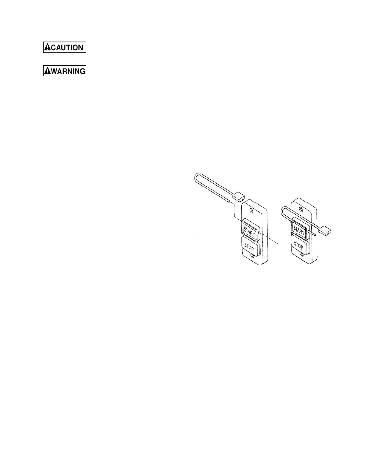
On-Off Switch Padlock
The jointer is equipped with a push-button
switch that will accept a safety padlock (see
figure – not included). To safeguard your
machine from unauthorized operation and
accidental starting by y oung chil dren, the u se of
a padlock is highly recommended. JET model
PD-LK-1 (Stock No. 709012) is available from
your local author iz ed J E T distributor or by calling
Walter Mei er (Manufacturi ng), Inc., at the phone
number on the cover of t his manual.
Introduction
Model PD-LK-1 On-Off Sw itch P adloc k
This manual is provided by W MH Tool Group cov ering the safe oper ation and mai ntenance procedure s
for Models JJ-6CSX, JJ-6CSDX and JJ-6HHDX Jointers. This manual contains instructions on
installation, safety precautions, general operating procedures, maintenance instructions and parts
breakdown. This machine has been designed and constr uc t ed to provide years of trouble free operat ion if
used in accordanc e with instructions set f orth in this manual. If there are any questions or com ments,
please contact your loc al supplier or Walter Meier, or visit our web site: www.jettools.com .
6
Page 7

Specifications
Model JJ-6CSX JJ-6CSDX
Stock Number – Bed and Stand Kit ................................ 708457K........................................... 708457DXK
Stock Number – Bed Assembly ..................................... 708457J............................................ 708457DXJ
Stock Number Stand...................................................... 708457S........................................... 708457DXS
Cutting Capacity ............................................... 6-1/16"W x 1/2"D................................... 6-1/1 6 "W x 1/2"D
Cutterhead Speed ...................................................... 4800 RPM.............................................. 6000 RPM
Number of Knives ...................................................................... 3............................................................ 3
Rabbeting Capaci ty .............................................................. 1/2"........................................................ 1/2"
Rabbet Ledge ........................................................ 3-1/8" x 8-3/4"........................................ 3-1/8" x 8-3/4"
Table Surface ............................... 7-3/8"W x 45-3/4"L x 31-1/4"H...................... 7-3/8"W x 56"L x 31-1/4"H
Fence ............................................................. 3-7/8"H x 29-1/8"L.................................. 3-7/8"H x 32-3/4"L
Knife Size ................................................... 6-1/16 " x 5/8" x 1/8 " T ........................... 6 - 1 /1 6 " x 3/4" x 5/64"T
Fence Tilt ................................................................... 45ºL, 45ºR ............................................ 45 ºL , 45ºR
Positive Stops...................................................... 45ºL, 90º, 45ºR...................................... 45ºL, 90º, 45ºR
Motor ................................................. 1HP, 1Ph, 60Hz, 115/230V.................... 1HP, 1Ph, 60Hz, 115/230V
pre-wired 115V pre-wired 115V
Net Weight (approx.)....................................................... 215 lbs.................................................... 237 lbs
Shipping Weigh t ............................................................ 230 lbs.................................................... 258 lbs
Model JJ-6HHDX
Stock Number – Bed and Stand Kit ............................... ......................................................... 708466DXK
Stock Number – Bed Assembly .................................... .......................................................... 708466DXJ
Stock Nu mbe r S ta n d..................................................... .............................................................. 708466S
Cutting Capacity ........................................................... ......................................................... 6"W x 1/2"D
Cutterhead Speed ........................................................ ............................................................ 6000 RPM
Number of Knives ......................................................... ............................................. 27 four-sided inserts
Number of Rows in Cutterhead ..................................... .......................................................................... 4
Table Surface ............................................................... .................................... 7-3 /8 "W x 56"L x 31-1/4"H
Fence ........................................................................... ................................................ 3-7/8"H x 32-3/4"L
Knife Ins e r t Size ........................................................... ....................................... 0.59”L x 0.59”W x 0.10T
Fence Tilt ..................................................................... ........................................................... 45 ºL , 45ºR
Positive Stops............................................................... .................................................... 45ºL, 90º, 45ºR
Motor ............................................................................ ........1HP, 1Ph, 60Hz, 115/230V (pre-wired 115V)
Net Weight (approx.)..................................................... ................................................................. 237 lbs
Shipping We ig h t .......................................................... ................................................................. 258 lbs
The above specifications were current at the time this manual was publi shed, but because of our policy of
continuous im provement, Walt er Meier (Manuf acturing), Inc. , reserves the ri ght to change speci fications
at any time and without pri or notice, without incurring obligations.
7
Page 8
Unpacking
This unit is shipped in two cartons. Open both
cartons and check for shipping damage. Report
any damage immediately to your distributor and
shipping agent. Do not discard any shipping
material unti l the Jointer i s assembled and running
properly.
Compare the contents of your cartons with the
following parts l ist to make sure all parts are intact.
Missing parts, if any, should be reported to your
distribut or. Read the instruction manual thoroughly
for assembly, maintenance and safety instructions.
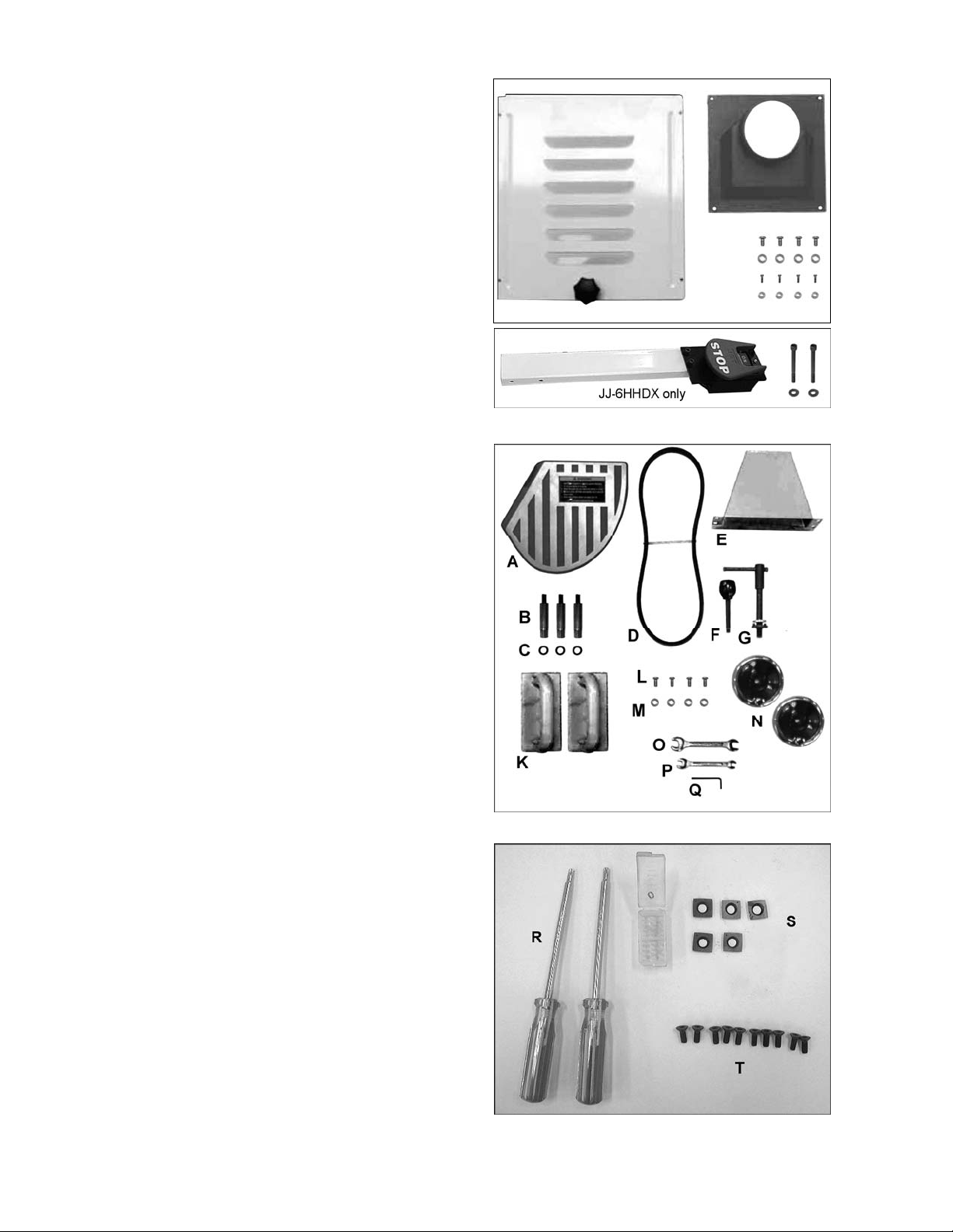
Stand Carton
1 Stand with Mot or
1 Stand Cover with Mounting Hardware
1 Dust Chute with Mounting Hardware
1 Pedestal Switch wi t h Mount ing Hardware (JJ-
6HHDX only)
Main Unit Carton
1 Bed Assembly
1 Fence Assembly
1 Cutterhead Guard ( A )
1 Belt Guard (E)
1 V-Belt (D)
4 1/4-20 x 1/2 Pan Head Screws (L)
4 1/4 Flat Washers (M)
1 Lock Handle, Flat Washer, and Loc k Nut for
Fence (G)
1 Fence Handle (F)
3 Lock Bolts (B)
3 3/8" Lock Washers (C)
2 Handwheel Assembly (N)
2 Push Blocks (K)
1 Operating Instr uc ti ons and Par ts Manual
1 Warranty Card
Tools Included for JJ-6CSX
1 12/14mm Open End Wrench (O)
1 8/10mm Open End Wrench (P)
1 3mm Hex Wrench (Q)
Tools Included for JJ-6CSDX
1 12/14mm Open End Wrench (O)
1 8/10mm Open End Wrench (P)
1 3mm Hex Wrench (Q)
1 4mm T-Hex Wrench
1 8mm Hex Wrench
Tools included for JJ-6HHDX:
1 12/14mm Open End Wrench (O)
1 8/10mm Open End Wrench (P)
1 3mm Hex Wrench (Q)
1 6mm Hex Wrench
2 Star Point Screwdrivers (R)
5 Knife Inserts (S)
10 Knife Insert Screws (T)
Stand Carton
Main Unit Carton
Tools included for Model JJ-6HHDX only
8
Page 9
Assembly
Unpacking and Cleanup
1. Carefully fini sh rem oving all content s f rom bot h
shipping cartons. Compare contents of the
shipping cartons wi t h the list of contents above.
Place parts on a protected surface.
2. Set packing material and shipping cartons to
the side. Do not discard until machine has
been set up and is running properly.
3. Clean all rust protected surfaces (bed, fence,
etc.) with kerosene or diesel oil. Do not use
gasoline, paint thinner, mineral spirits, etc.
These may damage paint ed surf ac es.
Cutterhead knives are
dangerously sharp! Use
extreme cautio n when cl eani ng .
4. Apply a thin layer of paste wax to the bright
surfaces of the fence and tables to prevent
rust.
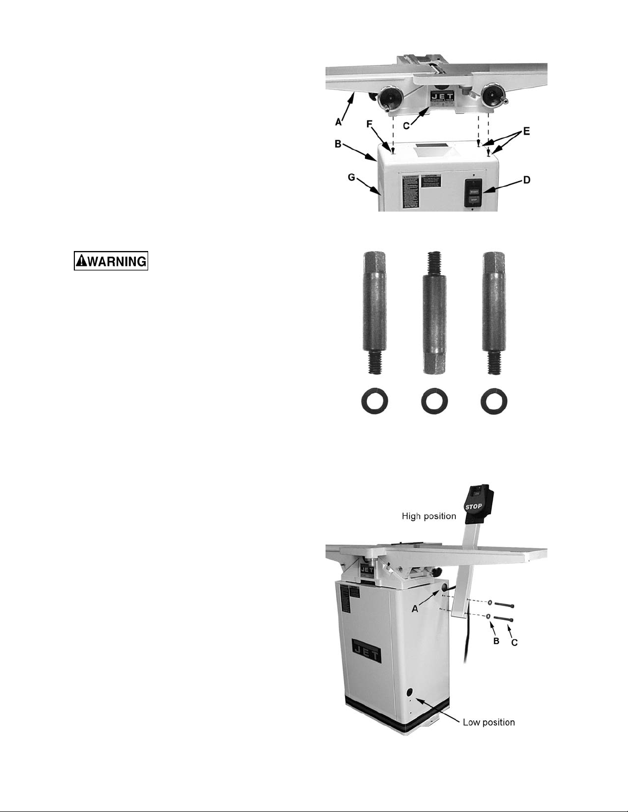
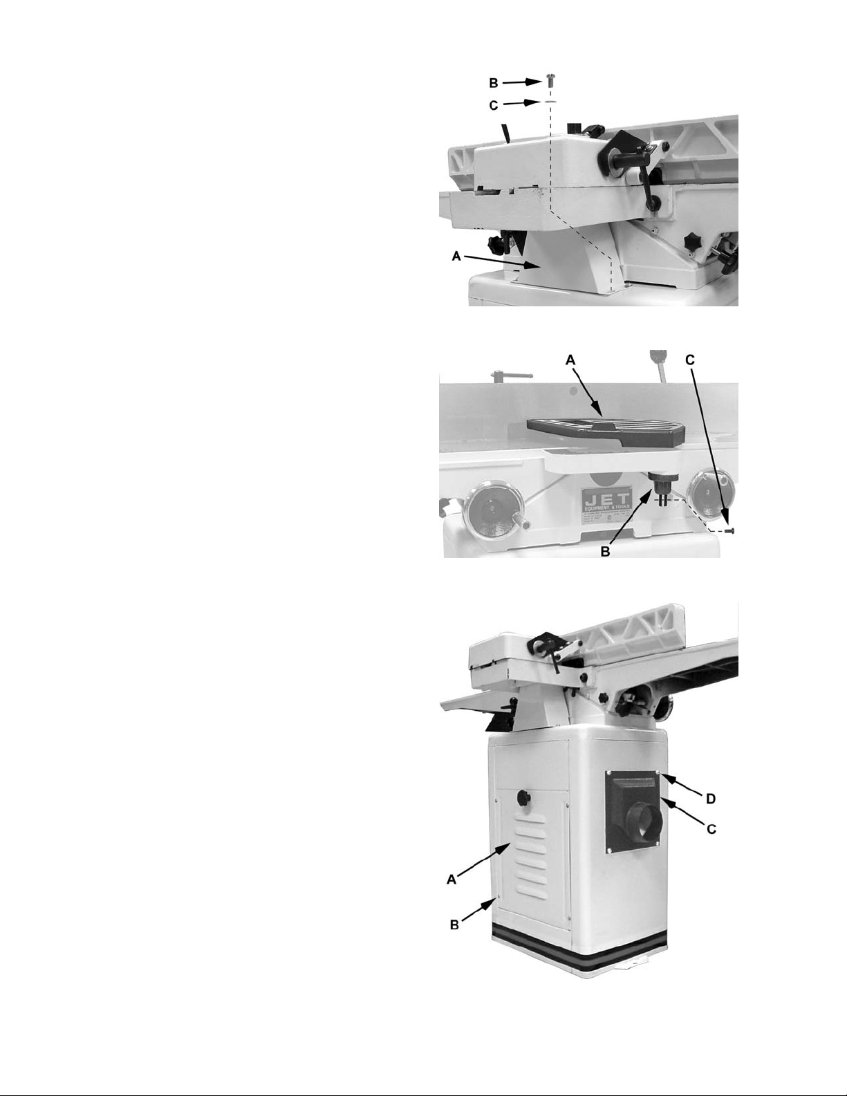
Installing Bed to Stand
Referring to Figur e 1:
1. Place bed assembly (A) on top of stand (B). Be
sure the identification label (C) on the bed
faces the sam e direction as the switch (D) on
the stand.
2. Line up two holes in the stand top (E) with
holes in the bed assembl y by viewing thr ough
the access door in rear side of the stand.
3. Attach stand to bed assembly by using two 3/8"
lock bolts and lock washers (Figure 2). Hand
tighten only at t his tim e.
Figure 1
Figure 2
4. Line up the third hole in the stand (F ) with the
hole in the bed assembly by viewing through
the dust chute (G).
5. Install the thi rd 3/8" lock bolt and lock washer
through the dust chute ( G) to secure t he bed to
the stand.
6. Tighten all three lock bolts with a 14mm
wrench.
Installing Pedestal Switch (JJ-6HHDX)
Referring to Figur e 3:
1. The switch may be installed in either high
position or low position to suit the operator.
Slide the connect ion plug through the ope ning
(A) and secure the pedestal switch using two
5/16”x3” screws (C) and 5/16” flat washers (B).
2. Connect the plug of t he pedestal switch to the
motor plug insi de the cabinet.
Figure 3
9
Page 10
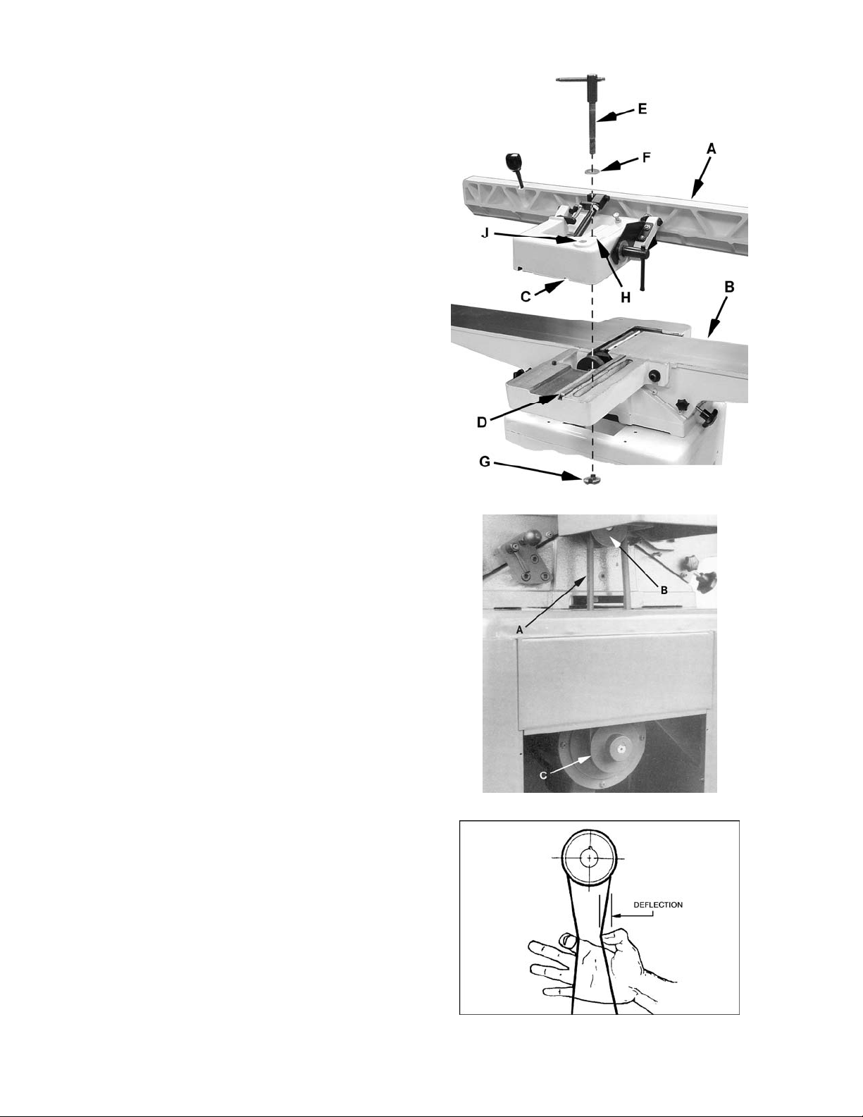
Installing Fence to Bed
Referring to Figur e 3a:
1. Take the lock handle ( E), flat washer (F), and
lock nut (G) from the carton.
2. Place the fence assembly (A) onto the table
(B). Be sure the key stock (D) on the bed lines
up with the channel (C) in the fence casting.
3. Place the flat washer (F) on hole (H)*; insert
the lock handle (E) through the fence casting
and the table casting.
4. Thread the lock nut (G) onto the lock handle
(E). Make sure the tab on the nut faces up and
engages the slot i n the tabl e c asting.
*Note: For rabbeting operations use hole (J).
Installing the Drive Belt
Referring to Figur e 4:
1. Place V-belt (A) onto cutterhead pull ey (B) and
through opening i n stand.
2. Pull V-belt down and place onto motor
pulley (C).
Note: If the belt i s difficult to roll on the pull ey,
loosen the motor m ounting screws.
3. Check to make sure that motor pulley and
cutterhead pul ley are v ertic ally aligned and the
V-belt does not contact the sides of the
opening in the base. If the pulleys are not
aligned, remove belt and adjust the motor
pulley in or out on t he motor shaft and then r eattach the belt.
4. The V-belt is properly tensioned when finger
pressure on the bel t half way bet ween the two
pulleys causes 1/2" def l ecti on (Figure 5). If the
belt is too loose, l oosen the four motor mount
bolts, push down on the motor to tension t he V belt, and tighten the mounting bolts.
Figure 3a
Figure 4
5. A new belt may have a tendency to stretch
slightly until broken in. After two hours of
operation, check belt tension again. Readjust
the tension if necessary.
Figure 5
10
Page 11
Installing Belt Guard
Referring to Figur e 6:
1. Place the belt guard (A) over the opening in the
stand.
2. Li ne up the holes in the stand wit h the holes in
the guard.
3. Attach the guard to the stand using four
1/4-20 x 1/2” pan head machine screws (B)
and four 1/4” flat washers (C).
Installing Cutterhead Guard
1. Remove the screw from the guard post.
Referring to Figur e 7:
2. Turn spring knob (B) approximately one and
one half revolutions counter-clockwise (as
viewed from the top) and hold.
3. Insert the guard post into hole i n table. Make
sure that the spring inside t he spring knob (B)
engages the slot i n guard post.
4. Thread the screw (C) back into the guard post.
5. Check for proper operation. The cutterhead
guard (A) must return fully to the fence when
released. If guard does not return fully, pull
guard, apply more tension to the spring knob
(B) by turning it another half turn counterclockwise, and re- insert guard. If guard cl oses
too quickly and stri kes fence too hard, release
some tension on the spring.
6. Insert screw (C) back into the guard post.
Figure 6
Figure 7
Installing Access Cover
Referring to Figur e 8:
Install access cover (A) by placing bott om of panel
in the stand and fastening with four #5-40 x 3/8"
pan head screws and four flat washer s (B).
Installing Dust Chute
Referring to Figur e 8:
Attach the dust chute ( C) to the base with four 1/4"
x 1/2" machine screws and four 1/4" washers (D).
Figure 8
11
Page 12
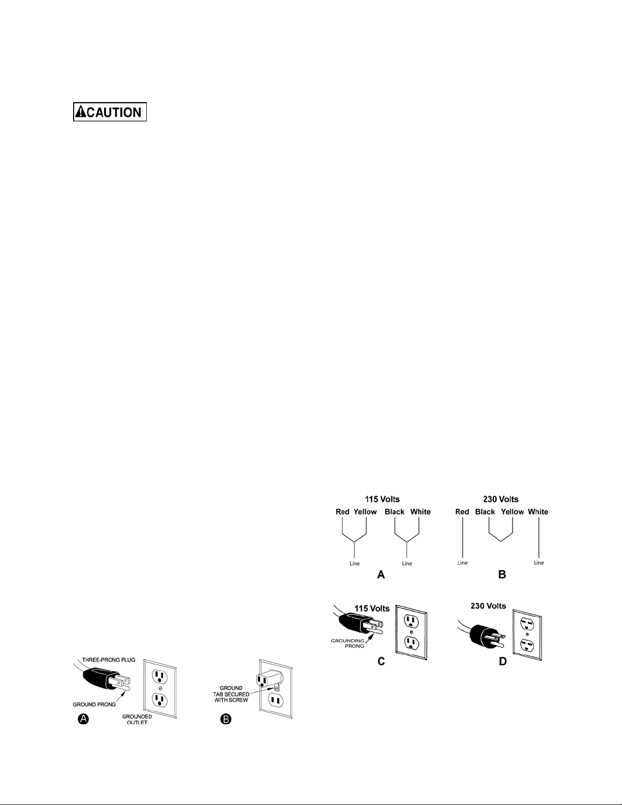
Electrical
Grounding Instructions
This jointer must be
grounded while in use to
protect the operat or from electric shock.
The temporary adapter should onl y be used unti l
a properly grounded outlet can be instal led by a
qualified electrician. This adapter is not
applicable in Canada. The green colored rigid
ear, lug, or tab, extending from the adapter,
must be connect ed to a permanent ground such
as a properly grounded outlet box.
In the event of a malfunction or breakdown,
grounding prov ides a path of least resistance f or
electric current to reduce the risk of electric
shock. This tool is equipped with an electric
cord having an equipment-grounding conductor
and a grounding plug. The plug must be
plugged into a matching outlet that is properly
installed and grounded in accordance with all
local codes and ordinanc es.
Do not modify the plug provided. If it will not fi t
the outlet , have the proper outlet i nstalled by a
qualified el ectrician. Improper connecti on of t he
equipment-grounding conductor can result in a
risk of electric shock. The conductor, with
insulati on having an outer surface t hat is green
with or without y ellow stripes, is the equipment grounding conductor . If r epair or r eplac ement of
the electric cord or plug is necessary, do not
connect the equi pment-groundi ng c onduc tor to a
live terminal.
Check with a qualified electrician or service
personnel if the grounding instructions are not
completely understood, or if in doubt as to
whether the tool i s properl y gr ounded. U se onl y
three wire ex t ensi on c or ds t hat have three- pr ong
grounding plugs and t hree-pole recept acles that
accept the tool’s pl ug.
Repair or replace a damaged or worn cord
immediately.
230 Volt Operation
Referring to Figur e 10:
If 230V, single-phase operation is desired, the
following instr uc tions must be followed:
1. Disconnect the machine from the power
source.
2. The Jointer motor has four numbered leads
that are factory connected for 115V
operation, as shown in (A). For 230V
operation reconnect the leads as shown in
(B).
3. The 115V attachm ent plug (C) supplied with
the Woodworking Jointer must be replaced
with a UL/CSA li sted plug suitable for 230V
operation (D) . Contact your local Author ized
JET Service Center or qualified electrician
for proper procedures to install the plug.
The Woodworking Joi nter must comply with
all local and nati onal c odes after the 230-volt
plug is installed.
4. The Woodworking Jointer with a 230-volt
plug should only be connected to an outlet
having the same configuration as shown in
(D). No adapter is available nor should be
used with the 230-volt plug.
115 Volt Operation
Referring to Figur e 9:
As receiv ed f rom t he f actory , your W oodworking
Jointer is ready to run at 115-volt operation. This
Woodworking J ointer, when wired for 115 volt, is
intended for use on a circuit that has an outl et
and a plug that look like the ones illustrated in
(A). A temporary adapter, which looks like the
adapter shown in (B), may be used to connect
this plug to a two-pole receptacle if a properly
grounded outlet is not av ailable.
Figure 9
Figure 10
Page 13
Extension Cords
Make sure your extension cord is in good
condition. W hen using an ex tension cord, be sure
to use one heav y enough to carry the current your
machine will draw. An undersized cord will cause
a drop in the line voltage resulting in power loss
and overheati ng. T able 1 sho ws the cor rect si ze to
use depending on t he cord length and namepl ate
ampere rating. If in doubt, use the next heavier
gauge. Remember, the sm aller the gauge number,
the heavier the cord.
Adjustments
Recommended Extension Cord Gauges (AWG)
Extension Cord Length in Feet *
Amps
25 50 75 100 150 200
< 5 16 16 16 14 12 12
5 to 8 16 16 14 12 10 NR
8 to 12 14 14 12 10 NR NR
12 to 15 12 12 10 10 NR NR
15 to 20 10 10 10 NR NR NR
21 to 30 10 NR NR NR NR NR
Drive Belt Tension
See step 4 of Installing the Driv e B elt.
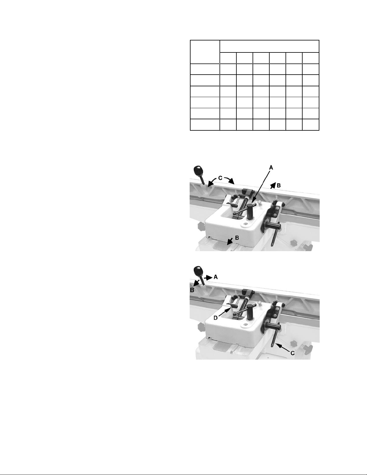
Fence Movement
The fence can be moved forward or backward
across the width of the table (B, Fig. 11). It also tilts
up to 45 degre es forward and has a positiv e stop
at 90 degrees.
To slid e fence forward or backward
When edge jointing, the fence assembly should
periodically be moved to different positions to
distribut e wear on the c utt er head k nives.
1. Loosen the locking handle (A, Fig. 11).
2. Push the enti re fence assembly (B, Fig. 11) t o
the desired position, and tighten the locking
handle.
To tilt fence forward
The fence c an be tilted for ward to any angl e down
to 45 degrees.
1. Loosen locki ng handle ( C, Figure 12).
2. Move the lever forward (A, Figure 12) to the
desired angle do wn t o 45 degr ees. O r y ou c an
place your reference piece on the table and
against the fence, and adjust the fence until
the angle of the fence matches the bevel of
your gauge piece.
*based on li mi ti ng th e lin e voltage drop t o 5V at 15 0% of th e
rated amp eres.
NR: Not Recommended.
Table 1
Figure 11
3. Tighten locki ng handle (C, Figure 12).
To tilt fence backward
1. The fence can be tilted backward up to 45°
(that is, for a tot al included angle of 135° from
table surface).
2. Loosen locki ng handle ( C, Fig. 12).
3. Flip the 90° stop bl ock (D, Fig. 12) out of the
way.
4. Move the lev er (B, Fi g. 12) bac k to t he desired
angle up to 135 degrees. Or you c an plac e
Figure 12
your bevel ed reference pi ece on the table and
against the f ence, adjusting the fence until t he
angle of the fence matches the bevel of your
gauge piece.
5. Tighten locki ng handle (C, Fig 12).
Important: When the tilted operation is finished and
the fence is returned t o 90°, do not forget to flip the
90° stop block (D, Fig. 12) back to its original
position.
13
Page 14

Fence Stop Adjustments
Periodically check the 90° and 45° backward
(135°) tilt accuracy of the fence with an angle
measuring device, such as an adju st able square or
machinist’s protractor.
90º Fence Adjustment
Referring to Figur e 13:
The 90º stop is control led by the st op bolt (E) and
the stop plat e (C).
1. Set the infeed t able to approx im ately t he sam e
height as the outf eed table.
2. Move the fence by releasing lock handle (D)
and pushing the fence assembly until it
overlaps the tables (B).
3. Tighten lock handle (D).
4. Adjust the fence to a 90º angle by releasing
lock handle (J), pulli ng up on the fence handle
(A), and tightening the lock handle (J).
Note: The stop bolt (E) should be resting
against the stop plate (C).
Figure 13
5. Place an angl e measuring dev ice on the t able
and against the f ence to confirm a 90º setti ng
(A, Fig. 14).
6. If the fence is not square to t he table, release
the lock handle (J), loosen the hex nut (F), and
turn the stop bolt (E) unt il the fence is square
to the table.
7. Tighten the lock nut (F) to retain the setting.
Tighten the lock handle (J).
45º Fence Backward Stop Adju stment
Referring to Figur e 15:
The 45º fence backward stop (fence positioned
away from the operator) is controlled by the stop
bolt (E).
1. Loosen the lock handle (A). Move the stop
plate (D) out of t he way and position t he fence
at the 135º angle. Make sure the fence sits
against the stop bolt. ( E ).
2. Tighten the lock handle (A)
3. Place an angl e measuring dev ice on the t able
and against the f ence t o confirm a 135º sett ing
(A. Fig. 16).
Figure 14
Figure 15
4. To adjust, loosen the lock nut (F), tur n the stop
bolt (E) until a 135º angle is obtained.
5. Tighten the lock nut (F).
Figure 16
14
Page 15

Infeed Table Depth Stop
Referring to Figur e 17:
The infeed tabl e depth stop (A) l imits the depth of
a cut (set by adjusti ng the infeed table handwheel)
to a maximum depth of 1/8”. For normal
operations, the depth of cut should never exceed
1/8", except f or rabbet ting operations.
If a rabbeting operation is desired:
1. Lower the infeed table to 1/8", which will cause
the depth stop limiter to engage.
2. Loosen t he lock handl e (B) and pull out on t he
stop handle (C).
3. Continue lowering the table to the desired
depth of cut.
Important: Never override the depth stop limiter
unless performing rabbeting operations.
Gib Adjustment
After a peri od of use, the gibs may become l oose
and need adjusting.
To adjust (ref er t o Figure 18) :
Figure 17
1. Loosen setscrew locknuts (A) and gib lock
screws (B).
Note: The infeed table has three gib
adjustment screws A (Infeed). The outfeed
table has two gib adjustment screws
A (Outfeed) and two gib lock wing screws (B).
2. Tighten each setscrew 1/4 turn star ting at the
bottom and working up. If a 1/4 turn does not
remove all play, take anot her 1/ 4 turn. Repeat
a 1/4 turn at a time for all three (or two) set
screws until pl ay is rem ov ed.
3. Tighten wing screws (B) and lock nuts (A).
Important: If gibs are adjusted, also perform the
Outfeed Table Adjustment to ensure the proper
knife height in r elation to the outfeed table.
Figure 18
15
Page 16

Setting Cutterhead Knives (JJ-6CSX)
Cutterhead knives are
dangerousl y sharp! Use extreme caution when
inspecting, removing, sharpening or replacing
knives into the cutterhead. Failure to comply
may cause seriou s injury!
1. Carefully number each blade with a magic
marker to make them easier to differentiate.
2. Rotate the cutterhead by turning the
cutterhead pul ley and determ ine t he 12 o'cl ock
position of knife number one. The 12 o'clock
position i s the highest point a blade will r each
in the cutting arc.
3. Loosen table lock screw (A, Fig. 19) and gib
lock screw (B, Fig. 19) and rai se the outfeed
table to the height of blade number one by
turning hand wheel (A, Fig. 20). Counterclockwise will cause the outfeed table t o raise.
Clockwise will cause the outfeed table to
lower. Set a straight edge on the outfeed
table. Posi tion of the table and straight edge
should look like Figure 21. Use care when
handling the str aight edge near the blades so
as not to damage them.
4. When the outfeed tabl e and bl ade num ber one
are the same hei ght, tighten gib and tabl e lock
screws.
Important: Do not change the setting for the
outfeed tabl e again. This will only change if the
blades are replaced.
5. Bring the straight edge toward the left of the
jointer and conf irm t hat blade num ber one is at
the same height at the lef t of the t able as it is
at the right side of the table. (Fig. 22)
Figure 19
Figure 20
6. If blade is higher or lower at the right of the
table than it is at the left, slightly loosen four
screws (A, Fig. 21) by turning clockwise as
viewed from the infeed table. Blades are
adjusted with jac ki ng screws To lower, tur n the
screw clockwise. To raise, turn the screw
counter-clockwise.
Blades are set at the proper height when the
top of the blades are 1/16" above the
cutterhead.
7. Alternately tighten four screws to hold each
blade in place.
8. Repeat this process wit h blades two and three.
The outfeed table and cutterhead knives are
correctly adjusted when all three blades are
parallel to the outfeed table and all three
blades are set at the same height in the
cutterhead.
Figure 21
Figure 22
16
Page 17

Replacing Knives (JJ-6CSX)
Planer knives are dangerously
sharp. Use extreme caution when inspecting,
removing, sh arpening, or repl acing knives i nto
the cutterhead. Failure to comply may cause
serious injury.
1. Disconnect machine from the power source.
2. Remove blade guard by turning the knob
(A, Fig. 23) clockwise while lift ing up on blade
guard.
Blades are sharp! Use great
care when hands are around
blade area!
3. Loosen four screws (A, Fig. 24).
Note: Loosen screws by t urni ng in a c loc kwise
direction as viewed from the infeed table.
Carefully remove the knife (C, Fig. 24) and the
lock bar with screws (B, Fig. 24).
Repeat for the other t wo blades.
4. Before assembly, clean all parts thoroughly
and clear cutt erhead knife sl ots of any dust or
debris.
Figure 23
5. Insert knife into the cutt erhead channel maki ng
sure it faces the pr oper dir ec ti on.
6. Insert lock bar and screws and ti ghten to hold
in place. Blades are set at the proper height
when the top of the blade is 1/16" abov e the
cutterhead. Do not ti ghten firmly at this time.
7. Repeat for other two blades.
8. To set the knives to the outfeed table and to
the same height in the cut terhead, s ee Setting
Cutterhead Knives (JJ-6CSX) on page 16.
Figure 24
17
Page 18

Outfeed Table Adjustmen t
When you receive the jointer, the knives have
been pre-set at the factory. However, the height
and paralleli sm of t he kniv es with t he outf eed tabl e
should be checked, and any needed adjustments
made, before putting the jointer into operation.
Adjust the height of t he outf eed table as follows:
1. Disconnect jointer from power source.
2. Carefully num ber each blade with a marker to
make them easier to differentiate.
3. Place a straightedge upon the outfeed table
and extend i t over the cutterhead (Figures 25
and 26).
Jointer kni ves are dangerously
sharp. Do not grab the
cutterhead itself to ro tate it! Failure to comply
may cause seriou s injury.
4. Rotate the cutterhead, using the drive belt or
pulley, until k nife number one is at it s highest
point. The apex of the knife shoul d just barely
come in contact with the straightedge.
If the apex of t he knif e number one j ust makes
contact with the str aightedge, no adjustment is
required f or the outfeed table. P roceed to the
Setting Cutt er head K niv es section.
If the apex of the knife number one comes
below the straightedge (a gap exists) or
pushes the straightedge up, proceed with the
following steps:
5. Loosen both gib lock screws (B, Fig. 18) and
the lock knob (Figure 25).
Figure 25
6. Raise or lower the outfeed table until the
straight edge cont acts the knife tip, as shown
in Figure 26. Using the drive belt or pulley,
rock the cutterhead slightly to make sure the
apex of the knife i s just barely contacting the
straight edge.
When adjustment is complete:
7. Lock the outfeed table at that setting by
tightening the lock knob (Figure 25) and gib
lock screws (B, Fig. 18). The outfeed table
adjustment i s com plete.
The outfeed table adjustm ent is only made against
one knife (blade number one was arbitrarily
selected here). After the outfeed table has been
set at the correct height, do not change it except
for special operations or after replacing k niv es.
After this adj ustment is compl eted, it is necessary
to proceed to the Setting Cutterhead Knives
section to verify that all three knives are at the
correct height and par allel to the outfeed table.
Figure 26
18
Page 19

Setting Cutterhead Knives (JJ-6CSDX)
Note: Before setting knives for model JJ-6CSDX
Jointer, the Outfeed Table Adjustment should be
done to ensure the proper k nife height in r elation to
the outfeed table.
Knives for the JJ-6CSDX cutterhead are adjusted
by means of a cam. It is important to note t hat the
entire adjustment is accomplished within one
complete r otation (360 degrees) of the cam. A full
rotation of the cam will cause the knife blade to
move a total of .015” from one extreme to the
other. Turni ng the cam more t han one full rotation
will not further adjust the knife setting, but will
simply begin the adjustment all over again. The
knife adjustment pr oc edure is outlined below.
Cutterhead knives are
dangerousl y sharp! Use extreme caution when
inspecting, removing, sharpening or replacing
knives into the cutterhead. Failure to comply
may cause seriou s injury!
Figure 27
To adjust (ref er t o Figures 27 & 28):
1. Disconnect jointer from power source.
2. Carefully num ber each blade with a marker to
make them easier to differentiate.
3. Place a straightedge ac ross the outfeed tabl e
extending it over the cutterhead towards one
end of the knife.
Cutterhead knives are
dangerousl y sharp. Do no t grab the cu tterhead
itself to rotate it! Failure to comply may cause
serious injury.
4. Rotate the cutter head back a nd for th using the
drive belt or pull ey, until knif e number one is at
its highest poi nt. The apex of the knife should
just barely come in contact with the
straightedge.
5. Move the straightedge towards the other end
of the knife and repeat step 4.
The apex of t he knife at bot h ends of the k nife
must just make contact with the straight edge. If
the apex of the knife comes below the
straightedge (a gap exists) or pushes the
straightedge up, pr oc eed to the next step.
6. Using a 4mm hex wrench, slightly loosen the
four gib screws.
7. Using a 3mm hex wrench, loosen the cam
locking scre ws to per mit adjustment of the cam
(described in t he next st ep) .
Important: Always keep the cam locking
screws snug enough so that t he c am can’t
Figure 28
rotate freely. This is especially important for
when the cam is rotated counterc lockwise since
this acti on will cause the cam l ocking screw to
loosen furt her.
8. Using an 8mm hex wrench, adjust the cam.
This is a very sensitive adjustment. Start by
rotating t he cam in a clockwise direc tion just a
few degrees.
9. Next, keep the cutterhead steady by firmly
holding on to t he pulley, place a piece of wood
pressed against the knife’s edge and press to
properly seat the blade.
10. Check your progress by repeati ng steps 4 and
5. If the knife becomes m ore out of adjustment,
turn the cam in the other direc tion.
11. The adjustment is almost complete when the
requirements described in Steps 4 and 5 are
met.
12. Next, while pressing the k nife firml y against the
cam, snug the t wo inside gib screws that hold
the gib and knife in place. Verify that t he k nife is
still in adjustment (steps 4 and 5).
13. Tighten the two outside gib screws, then the
two inside gib screws. Verify that the knife is
still in adjustment (steps 4 and 5).
14. Tighten the gib lock screws.
15. Repeat thi s entir e procedure for the rem aining
two knives.
19
Page 20

Replacing Knives (JJ-6CSDX)
Join ter knives are dangerously
sharp. Use extreme caution when inspecting,
removing, or replacing knives.
To remove/r eplac e a knife (Refer to Figure 29):
1. Remove four gib screws (A) with a 4mm hex
wrench.
2. Remove the gib ( B ) and knife (C).
If the knif e is being reused (kniv es are double-
edged), clean t he knife, gib and cut terhead of
all pitch and debris.
3. Lay the new knife or unused edge of the old
knife back onto the cutterhead (D).
4. Replace the gib (B) and screws (A). Finger
tighten only at t his tim e.
5. Press against the cutting edge of the knif e at
the center of the blade with a piece of wood.
DO NOT USE FINGERS! This is to ensure t hat
the cam is making proper contact with the
knife.
6. Snug the inside two screws, then the outside
two screws.
7. Release the piece of wood pressing against
the knife and tight en the gib screws.
8. Replace the rem aining two blades by repeating
steps 1 – 7.
9. Determine if kniv es need to be set.
Follow the Outfeed Table Adjustment section
steps 3 and 4 only t o determi ne if knives need
to be set. Do not complete the entire
outfeed table adjustment. If knives need to
be set, proceed to the Setting Cutterhead
Knives section.
Figure 29
Setting Knives for Rabbeting and Nicks
(NOTE: Rabbeting is not applicable to the JJ6HHDX helical head jointer)
To position t he kniv es for rabbet cuts, take a shop
scale with 1/32” graduations and place it against
the end of t he c utterhead. Sli de the knife out until it
is at the 1/32” m ark on the scale; t hat is, the knife
will now be 1/32” beyond the edge of the
cutterhead. The gib should remain in normal
position, even with the edge of the cutterhead.
(Figure 30). This adjustment will ensure that the
knife clears the end of t he gib and cutterhead, and
has good contact with the workpiece. (See the
Rabbeting section for further information.)
Note: This will also corr ect for small nicks without
requiring r eplac ement of knives.
Figure 30
20
Page 21

Rotating and Replacing Knife Inserts (JJ-6HHDX)
Knife inserts are dangerously
sharp. Use extreme caution when inspecting,
removing, or replacing knife inserts.
The knife inserts on the model JJ-6HHDX Jointer
are four-sided. When dull, simply remove each
insert, rot ate it 90° for a fresh edge, and r e-install
it. No further adjustment is necessary.
Use the two provided star point screwdrivers to
remove the knife insert screw. Use one of the
screwdrivers to help hold the cutterhead in
position, and the other to remove the screw. See
Figure 30a. It is advisable to rotate all insert s at the
same time to maintain consistent cutting. However,
if one or m ore knif e inserts dev elops a nick , rotat e
only those inserts t hat ar e aff ec ted.
Each knife insert has an etched r eferenc e mark so
you can keep track of the rotations.
IMPORTANT: When removing or rotating inserts,
clean saw dust fr om the screw, the insert, and the
cutterhead platform. Dust accumulation between
these element s can prev ent the i nsert f rom seati ng
properly, and may affect the quality of the cut.
Before installi ng each screw, l ightly coat the screw
threads with mac hine oil and wipe off any excess.
Figure 30a – HH models only
Figure 31
Securely ti ghten each screw which hol ds the knif e
inserts before oper ating the planer!
Make sure all knife insert
screws are tightened securely. Loose inserts
can be propell ed at high speed from a rotating
cutterhead , cau sin g inju ry.
Determining Correct Table Height
When you receive the jointer, the knives have
been pre-set at the factory. However, the height
and paralleli sm of t he kniv es with t he outf eed tabl e
should be checked, and any needed adjustments
made, before putting the jointer into operation.
The outfeed table and cutterhead knives are
correctly adjusted when all three blades are
parallel to the outfeed table and all three blades
are set at the same height in the cutterhead.
Outfeed table t oo high – If the outfeed tabl e is too
high, a curved finished surface results (Figure 31).
Outfeed table t oo low – If t he outfeed table i s too
low, the work will have a gouge, or snipe, at the
end of the cut (Figur e 32).
Outfeed table at correct setting – Figure 33
illustrat es the correct setting of outf eed table level
with the knives. T he workpiece will rest firmly on
Figure 32
Figure 33
both tables with no open space under the finished
cut
21
Page 22

Operating Controls
1. Hand Wheel for Outfeed Table
2. Outfeed Table
3. Fence
4. Fence Adjustment Handle
5. Cutter Guard
6. Infeed Table
7. Hand Wheel for Infeed Table
8. On/Off Switch
Operation
Important: Before operating the jointer, make
sure all kni ves or knife inserts are seated and
secure in the cutterhead.
If you are inexperienced at jointing, use scrap
pieces of lum ber to check settings and get t he feel
of operations befor e att em pting regular work.
Stabilize l ong workpieces by using an a ssistant, or
roller stands set level with the outfeed or infeed
table surface.
The fence should be adjusted to create minimum
exposure to the cutterhead during the jointing
operation.
9. Table Lock Knob
10. Fence Tilt Lock Handle
11. Belt Guard
12. Fence Travel Loc k Handl e
13. Depth Limiter
Check the following before operating the joint er:
Outfeed table must be set level with the high
point of the knives or k nif e inserts.
Fence adjusted for minimum exposure of
cutterhead, and loc k ed at desir ed angle.
The cutterhead guard must be in place and
operating properly (except when rabbeting) .
Infeed tabl e set for desi r ed depth of cut.
Stand away from the cutterhead and turn the
machine on f or a f ew moments. Listen f or any
odd noises, rubbings, vibrations, etc. Correct
such problem s before at tempting oper ations on
the jointer.
Carefully check your workpiece for knots, holes,
staples or any foreign material that might
damage kniv es or pose a risk of kic kback. Also
check the workpiec e for grain orientation.
22
Page 23

Hand Placement
Never pass hands d irectly over
the cutterhead .
At the start of the cut, the left hand holds the
workpiece fi rmly agai nst t he infeed t able and f ence
while the right hand pushes the workpiece in a
smooth, even motion toward the cutterhead
(Figure 34). After the cut is under way, the new
surface rests firmly on the outf eed table. The left
hand is transferred to the outfeed side and presses
down on this part of the workpiece, at the same
time maintaining flat contact with the fence. The
right hand presses the workpiece forward and
before the right hand reaches the cutterhead it
should be moved to the work on t he outf eed table.
Surfacing
Figure 34
Always use a hold down or
push block when surfaci ng stock.
Surfacing, or j ointing the f ace of stock, is shown i n
Figure 35. A djust the inf eed table for depth of cut.
Cuts of approximately 1/16” at a time are
recommended, as this allows better control over
the materi al being surf aced. More passes can then
be made to reach the desired dept h.
Edge Jointing
Edge Jointing (Figure 36) is the most common
operation f or the j ointer. S et fence square with the
table. Depth of cut shoul d be the minimum required
to obtain a straight edge. Do not make cut s deeper
than 1/8" in a single pass. Hold the best face of the
workpiece firmly against the fence throughout the
feed.
Figure 35
Figure 36
23
Page 24

Rabbeting
A rabbet is a groove cut al ong the edge of a board.
See Figure 37. The width and thickness of the
wood to be rabbeted depends upon t he width and
length of the rabbet. However, never rabbet a
piece of wood less than 12” l ong.
Note: The knives must be extended beyond the
cutterhead by 1/32”. See the Setting Knives for
Rabbeting and Nicks section on page 20 for this
procedure.
A rabbet cut requires removal
of the guard. Use extreme
caution and keep hands clear of cutterhead.
Always re-install guard immediately after
rabbeting operation is completed.
Use push blocks to rabbet cut whenev er possible.
The rabbeting capacity is 1/2”.
1. Disconnect jointer from power source.
2. Set fence for desir ed width of rabbet.
3. Check width of the rabbet by measuring the
distance from the end of a knife in the
cutterhead to the fence.
Figure 37
4. Re-connect power. It is easier and safer to
take a series of shal low cuts. Lower the i nfeed
table 1/32” at a time and make successive cuts
until the desired depth of rabbet has been
obtained. See Figure 37.
Jointing Short or Thin Work
When jointing short or thin work pieces, use a push
block to eliminate all danger to the hands. Two
push blocks are shipped wit h your joint er. You can
also make your own easily from scrap material.
Examples are shown in Fi gur e 38.
Jointing Warped Surfaces
If the wood to be jointed i s cupped or bowed, place
the concave si de down, and take li ght cuts until the
surface is flat.
Avoid forci ng such materi al down against the tabl e
– excessive pressure will spring it while passing
the knives, and it will spring back and remain
curved after the c ut is completed.
Figure 38
24
Page 25

Beveling
To cut a bevel, lock the fence at the required angle
and run the work piece across the knives while
keeping it firmly against the fence and tables.
Several passes m ay be necessary to achiev e the
desired result.
Although the fence may be
tilted in or out for a bevel cut, it is
recommended for safety reaso ns that the f ence
be tilted in toward the operator, making a
cradled cut.
Direction of Grain
Avoid feeding work into the jointer against the
grain. This may result in chipped and splintered
edges. See Figure 39. Feed with the grain to
obtain a smooth surfac e, as shown in Figure 40.
Maintenance
Blade Care
Figure 39
Blades are extremely sharp!
Use caution when cleaning or
changing. Failure to co mply may cau se serious
injury!
When gum and pitch collect on the blades,
carefully r emove with a strong solv ent. Failure t o
remove gum and pitch build up may result in
excessiv e fric ti on, blade wear and overheating.
When blades becom e dull, t ouch up blades. See
Sharpening the Knives. NOTE: This does not appl y
to the JJ-6CSDX or JJ-6HHDX models – knives or
inserts must be rotated or replaced on these.
Sharpening the Knives (JJ-6CSX only)
Blades are extremely sharp!
Use caution when handling.
Failure to compl y may cause seri ou s in ju ry!
1. Disconnect the machine from the power
source.
2. Remove the blade guar d and belt cover.
3. To protect the infeed table from scratches,
partiall y cover the sharpeni ng stone with paper
(Figure 41).
4. Lay the stone on the infeed t able.
5. Lower t he inf eed table and turn t he cutter head
by turning the cutterhead pulley. The infeed
table height is set properly when the stone's
surface is flush with the knife bevel.
Figure 40
Figure 41
6. Keep the cutterhead from rotating by grasping
the cutterhead pulley while sliding the stone
back and forth across the table.
7. Take the same amount of passes for all three
blades.
When the blades have been sharpened and still are
not cutting ef ficiently, trying t o touch up the blades
further will only cause the formation of a second
beveled edge. When t his start s to hap pen, i t i s tim e
to replace blades with another set. It is
recommended to keep a second set of blades on
hand so that they may be install ed while the fir st set
is being professional ly sharpened.
25
Page 26

Cutterhead Removal
The entire cutterhead assembly may be removed
for cleaning or f or bearing and bl ade replacement.
Some woodworkers keep a spare cutterhead with
replacement blades should the origi nal cutterhead
have to be repaired.
Blades in the cutterhead are
sharp! Use extreme caution
when handling the removal of the cutterhead.
Failure to compl y may cause seri ou s in ju ry!
To remove the cutterhead (including bearings,
studs, and housing) from the base casting:
Referring to Figur e 42:
1. Disconnect the machine from the power
source.
2. Remove the front blade guard (A) and
screw (H).
3. Remove the lock handle (B), washer (C) and
lock nut (D) securing the fence assembly (E) to
the table (F).
4. Lift the fenc e as s em bly (E) from the table.
5. From the left side of the stand, remove the
dust chute (G ). Fr om th e bac k of t he ma chi ne
remove the cabinet ac c es s cover (not shown).
Referring to Figur e 43:
6. Using an 8mm hex wrench, loosen two hex
cap screws underneath fenc e base casting (E)
that secure the casting to the table (F).
Remove the fence base casting and set aside.
7. Remove four screws and washers (A) securing
the belt guard (B). Remove the belt guard.
8. Remove the V-belt (C) from the cutterhead
pulley (D). If necessary, loosen the motor
mounting screws with a 12mm wrench to
provide slack on the V- belt.
9. Using a 3mm hex wrench, loosen two set
screws that secure the cutterhead pulley (D) to
the cutterhead shaf t. Set the pulley and shaft
key aside.
Figure 42
Figure 43
10. Using a 14mm wrench, remove two screws
(A, Fig. 44) and lock washers that secure the
cutterhead bearing housings to the base.
Note: These screws and lock washers are
more easily accessibl e through the dust chute.
11. Carefully remove the cutter head ( A , Fi g. 45).
12. Before placing the new cutterhead back into
the casting, t horoughly clean the "saddle" and
the bearing hou sings of saw dust and grease
so that they seat properly.
Figure 44
26
Page 27

13. T o re-install the cutt erhead, reverse the above
steps.
Note: Make sure that the fence base cast ing is
level with the Outf eed t able when securi ng.
Lubrication
Use a good grade of li ght grease on the steel
adjusting screws located in the raising and
lowering mechanisms of the work tables.
Occasionally, apply a few drops of light
machine oil to the infeed/outfeed gibs. This
permits the tabl es t o sli de freely.
The cutterhead bal l beari ngs are lif etim e lubri cat ed
and need no further care.
Figure 45
27
Page 28

Troubleshooting Operating Problems
Trouble Probable Cause Remedy
Finished stock i s
concave on back
end.
Finished stock i s
concave on front end.
Chip out.
Fuzzy grain.
Raise outfeed table until it aligns with
Knife is higher than outfeed table.
Outfeed table is higher than knife.
Cutting against t he gr ain. Cut with the grain whenever possible.
Dull knives or knife inserts.
Feeding workpiec e t oo fast. Use slower rate of feed.
Cutting too deepl y. Make shallower cuts.
Knots, imperfections in wood.
Wood has high moistur e c ontent.
Dull knives or knife inserts.
tip of knife. See Outfeed Table
Adjustment ( page 18) .
Lower outfeed table until it aligns with
tip of knife. See Outfeed Table
Adjustment ( page 18) .
Sharpen or replac e k niv es.
Rotate or replace knife inserts.
Inspect wood closely for imperfections;
use different stoc k if necessary.
Allow wood to dry or use diff er ent
stock.
Sharpen or replac e k niv es.
Rotate or replace knife inserts.
Cutterhead slows
while operati ng.
“Chatter” marks on
workpiece.
Uneven knife marks
on workpiece.
Feeding workpiec e too quickly, or
applying too much pressure to
workpiece.
Knives incor r ectly set.
Feeding workpiec e too fast.
Knives are nicked, or out of
alignm ent.
Feed more slowly, or appl y l ess
pressure to workpiece.
Set knives properl y as descri bed in the
Setting Cutt er head K niv es section.
Check that knif e slots are cl ean and
free of dust or debris.
Feed workpiece slowly and
consistently.
Align knives per the S ett ing Cutterhead
Knives secti on. Replace nicked knives
or correct for small nicks – see Setting
Knives for Rabbeting and Nic k s on
page 20.
28
Page 29

Troubleshooting Mechanical and Electrical Problems
Trouble Probable Cause Remedy
Machine will not
start/restart or
repeatedly t ri ps
circuit breaker or
blo ws fu se s.
No incoming power.
Building cir c uit break er trips or fuse
blows.
Switch or motor f ailur e ( how to
distinguish).
Motor overheat ed.
Verify unit is connected to power, onbutton is pushed in com plet ely , and
stop-button is di sengaged.
Verify that joi nter is on a circuit of
correct size. If circuit size is correct,
there is probably a loose el ectrical
lead. Check amp setting on motor
starter.
If you have access to a voltmeter, you
can separate a switch f ailure from a
motor failure by first, verifying
incoming volt age at 110/220+/-10%
and second, checking t he v oltage
between switch and motor at
110/220+/-10%. If incoming voltage is
incorrect, y ou hav e a power supply
problem. If voltage between switch
and motor is incorr ec t, y ou hav e a
switch probl em. If v oltage between
switch and motor i s corr ect, you have
a motor problem.
Clean motor of dust or debris t o allow
proper air circulation. Allow motor to
cool down before r estar ting.
Motor failure.
Unit incorrectly wired.
On/off switch failure.
Optional Accessories
708801 .............Knives for Model JJ-6CSX Jointer (set of 3)
708801DX ........Knives for Model JJ-6CSDX Jointer (set of 3)
708815 .............Push Block
1791212 ...........Knife Inserts for Model JJ-6HHDX (set of 10)
If electric motor is suspect, you have
two options: Have a qualified
electrician test the motor for function
or remove the motor and take it t o a
qualified elec tric motor repair shop
and have it tested.
Double check to confirm all electrical
connections are corr ec t. Refer to the
Wiring Diagram section to make any
needed correcti ons.
If the on/off switch is suspect, you
have two options: Hav e a qualified
electrician test the switch for function,
or purchase a new on/off switc h and
establish if that was the pr oblem on
change out.
29
Page 30

Parts
Ordering Replacement Parts
To order parts or reac h our service department, call 1-800-274-6848, Monday through F riday (see our
website for business hours: www.jetttols.com). Having the Model Number and Serial Number of your
machine avail able when you call will allow us to serve you quickly and ac c ur ately.
Fence – Parts All Models
Index No. Part No. Description Size Qty.
................. JEJ-FW ....................Fence Assembly Complete (JJ-6CSX) ................................................... 1
................. JJ6CSDX -FAC .........Fence Assembly Complete (JJ-6C SDX)................................................. 1
1 ............... JEJ-F01W ................Fence Body (JJ-6CSX) .......................................................................... 1
1A ............ JJ6CSDX-2 01 ..........Fence Body (JJ -6CSDX)........................................................................ 1
2 ............... JEJ-F14 ...................Fence Link............................................................................................. 2
3 ............... JEJ-F02W ................Tilt Plate (JJ-6CSX) ............................................................................... 1
................. JJ6CSDX -203 ..........Tilt Plate (JJ-6CSDX)............................................................................. 1
4 ............... JED-F16 ..................Threaded Stud....................................................................................... 4
5 ............... TS-0561031 .............Hex Nut ..............................................................3/8”-16........................ 4
6 ............... JEB-F09...................Handle................................................................................................... 1
7 ............... 5DF-I09 ....................Knob ..................................................................................................... 1
8 ............... 5CH-F1 3A ................Flat Head Socket Screw (JJ-6CSX) ....................5/16”x1-5/8” ................ 2
8A ............ TS-0207041 .............Socket Head Cap Screw (JJ-6CSDX) .................1/4”-20x3/4” ................ 2
9 ............... JED-F02 ..................Block (JJ-6CSX) .................................................................................... 1
9A ........... PJ882-142 ...............Fixed Block (JJ-6CSDX) ........................................................................ 1
10 ............. JEJ-F03 ...................Block ..................................................................................................... 1
11 ............. JEJ-F04 ...................Bolt........................................................................................................ 1
12 ............. TS-0561041 .............Hex Nut ..............................................................7/16”-14 ...................... 1
13 ............. JEJ-F05 ...................Stud ...................................................................................................... 1
14 ............. JEJ-F06 ...................Swivel Block .......................................................................................... 1
15 ............. JEJ-F07 ...................Plate ...................................................................................................... 1
16 ............. 5FF-J12 ...................Spring Pin...........................................................Ø4x12 ........................ 1
17 ............. JEJ-F08 ...................Hex Cap Bolt ......................................................................
18 ............. JEJ-F09 ...................Plate ...................................................................................................... 1
19 ............. TS-0561072 .............Hex Nut ..............................................................5/8”-18UNF ................ 2
20 ............. JEJ-F10 ...................Bushing ................................................................................................. 1
21 ............. JEJ-F11W ................Fence Bracket (JJ-6CSX ) ...................................................................... 1
................ JJ6CSDX-221 ..........Fen ce Bracket (JJ-6CSDX) .................................................................... 1
22 ............. TS-0680061 .............Flat Wash er ........................................................1/2”............................. 3
23 ............. JEJ-F12 ...................Lock Handle .......................................................................................... 2
24 ............. JED-F17 .................Lock Nut ................................................................................................ 1
25 ............. TS-0051051 .............Hex Cap Screw ..................................................5/16”-18x1” ................. 1
26 ............. TS-0561021 .............Hex Nut ..............................................................5/16”-18 ...................... 2
27 ............. TS-0051081 .............Hex Cap Screw ..................................................5/16”-18x1-3/4” ........... 1
28 ............. JED-F03 ..................Plate ...................................................................................................... 1
29 ............. TS-0813032 .............Screw .................................................................1/4”-20x1/2” ................ 2
30 ............. TS-0680021 .............Flat Washer (JJ-6CSX) .......................................1/4”............................. 2
................. TS-0680021 .............Flat Washe r (JJ-6CSDX) ....................................1/4”............................. 4
31 ............. TS-0561052 .............Hex Nut ..............................................................1/2”-20UNF ................ 2
32 ............. PJ882-144 ...............Pad Block (JJ-6CSDX) .......................................................................... 1
33 ............. TS-069204 ...............Flat Washer (JJ-6CSDX) ....................................#10 ............................. 2
34 ............. TS-0206021 .............Socket Head Cap Screw (JJ-6CSDX) .................#10-24x1/2” ................ 2
................... 1
30
Page 31

Fence – Assembly All Models
31
Page 32

Stand – Parts, JJ-6CSX and JJ-6CSDX
Index No. Part No. Description Size Qty.
1 ............... JI-Y01 W ...................Stand Body ............................................................................................ 1
2 ............... JI-Y01AW ................Access Cover ........................................................................................ 1
7 ............... TS-0267041 .............Set Screw ...........................................................1/4”-20x3/8” ................ 2
8 ............... JH-M10 ....................Motor Pulley (JJ-6CSX) ............................................................. ............ 1
................. 6296125...................Motor Pulley (JJ-6CSDX) ....................................................................... 1
9 ............... VB-A36 ....................V-Belt (JJ-6CSX) ................................................A-36 ........................... 1
................. VB-A37 ....................V-Belt (JJ-6CSDX) ..............................................A-37 ........................... 1
10 ............. JC-M07 ....................Lock Bolt* ...........................................................3/8”-16........................ 3
11 ............. TS-0720091 .............Lock Washer* .....................................................3/8”............................. 3
12 ............. TS-0680031 .............Flat Wash er ........................................................5/16” ........................... 4
13 ............. TS-0051031 .............Hex Head Bolt ....................................................5/16”-18x3/4” .............. 4
14 ............. TS-0561021 .............Hex Nut ..............................................................5/16”-18 ...................... 4
15 ............. TS-081B042.............Screw .................................................................#8-32x5/8” .................. 2
16 ............. 5EA-D05 ..................Star Washer .......................................................#8 ............................... 2
17 ............. TS-0560061 .............Hex Nut ..............................................................#8-32 .......................... 2
18 ............. TS-1550021 .............Flat Wash er ........................................................M4 .............................. 2
19 ............. JEX-S02 ..................Dust Chute ............................................................................................ 1
21 ............. TS-0680021 .............Flat Wash er* ......................................................1/4”............................. 4
22 ............. TS-081F032 .............Screw*................................................................1/4”-20x1/2” ................ 4
23 ............. 994542 ....................Switch ................................................................................................... 1
24 ............. JI-X02 ......................Power Cord ........................................................................................... 1
25 ............. 5QA-I04 ...................Strain Relief Bushing ............................................................................. 3
26 ............. JI-X04W ...................Motor ..................................................................1HP ............................ 1
................. JI-X04-AA ................Centrifugal Switch (not shown) .............................................................. 1
................. JI-X04 -B...................Capacit or (motor – not shown) ............................
................. JI-X04 -CA ................Capacitor Cov er .................................................................................... 1
................. JI-X04-DA ................Junction Box (motor – not shown) .......................................................... 1
................. JI-X04-EA ................Junction Box Cover (motor – not shown) ................................................ 1
................. JI-X02-A...................Motor Cord (not shown) ......................................................................... 1
................. JJ6CS-HK ................Hardware Kit (not shown) ...................................................................... 1
................. TS-152704 ...............Hex Key Wrench (3mm – not shown)* ................................................... 1
................. JJ6CS-OE W ............Open End Wr enc h (8/10mm – not shown)* ............................................ 1
................. JJ6CS-OE W2 ..........Open End W r enc h (12/14mm – not shown)* .......................................... 1
................. TS-227D081 ............Hex Wrench (8mm – not shown)** ......................................................... 1
................. JJ6CSDX-326A ........T-Hex Wrench (4mm – not shown)** ...................................................... 1
27 ............. JJ6-03CS .................Key.....................................................................5x5x30 ....................... 1
28 ............. 5AL-C1 0B ................Tapping Screw ...................................................M4x25 ........................ 2
30 ............. TS-0680031 .............Flat Wash er ........................................................5/16” ........................... 4
31 ............. PG-M02 ...................JET Logo Label ..................................................................................... 1
32 ............. JJ6CSX-332.............Warning Label ....................................................................................... 1
33 ............. JEB-S07 ..................Warning Label ....................................................................................... 1
34 ............. JEB-S08 ..................Voltage Label ........................................................................................ 1
35 ............. JEB-S09 ..................Switch Box ............................................................................................ 1
36 ............. TS-0720081 .............Lock Washer ......................................................5/16” ........................... 4
37 ............. TS-1550021 .............Flat Wash er* ......................................................M4 .............................. 4
38 ............. TS-0803032 .............Screw*................................................................#5-40x3/8" .................. 4
39 ............. TS-081F032 .............Screw*................................................................1/4”-20x1/2” ................ 4
40 ............. TS-0680021 .............Flat Wash er* ......................................................1/4”............................. 4
41 ............. JEY-S03W ...............Belt Guard ............................................................................................. 1
42 ............. JEY-S07 ..................Plate ...................................................................................................... 1
43 ............. TS-081C032 ............Screw .................................................................#10-24x1/2” ................ 2
44 ............. TS-069204 ...............Flat Washer ........................................................#10 ............................. 2
* included in Hardware Kit for JJ-6CSX
*,** included i n Hardware Kit for JJ-6CSDX
300MFD 125VAC ....... 1
32
Page 33

Stand – Parts and Assembly, JJ-6CSX and JJ-6CSDX
45 ............. TS-0561031 .............Hex Nut ..............................................................3/8”-16........................ 1
46 ............. JC-M05 ....................Door Latch............................................................................................. 1
47 ............. JC-M04 ....................Knob Screw ........................................................................................... 1
33
Page 34

Stand – Parts, JJ-6HHDX only
Index No. Part No. Description Size Qty.
1 ............... JJ6HH-301 ...............Stand Body ............................................................................................ 1
2 ............... JI-Y01AW ................Access Cover ........................................................................................ 1
7 ............... TS-0267041 .............Set Screw ...........................................................1/4”-20x3/8” ................ 2
8 ............... 6296125...................Motor Pulley .......................................................................................... 1
9 ............... VB-A37 ....................V-Belt .................................................................A-37 ........................... 1
10 ............. JC-M07 ....................Lock Bolt* ...........................................................3/8”-16........................ 3
11 ............. TS-0720091 .............Lock Washer* .....................................................3/8”............................. 3
12 ............. TS-0680031 .............Flat Wash er ........................................................5/16” ......................... 10
13 ............. TS-0081031 .............Hex Cap Screw ..................................................5/16”-18x3/4” .............. 4
14 ............. TS-0561021 .............Hex Nut ..............................................................5/16”-18 ...................... 4
15 ............. JJ6HH-315 ...............Switch Arm ............................................................................................ 1
16 ............. JJ6HH-316 ...............Cord Protector ....................................................................................... 2
17 ............. TS-0208141 .............Socket Head Cap Screw* ...................................5/16”-18x3” ................. 2
18 ............. TS-0680031 .............Flat Wash er* ......................................................5/16” ........................... 2
19 ............. JEX-S02 ..................Dust Chute ............................................................................................ 1
21 ............. TS-0680021 .............Flat Wash er* ......................................................1/4”............................. 4
22 ............. TS-081F032 .............Screw*................................................................1/4”-20x1/2” ................ 4
26 ............. JI-X04W ...................Motor ..................................................................1HP ............................ 1
................. JI-X04-AA ................Centrifugal Switch (not shown) .............................................................. 1
................. JI-X04 -B...................Capacit or (motor – not shown) ............................300MFD 125V A C ....... 1
................. JI-X04 -CA ................Capacitor Cov er .................................................................................... 1
................. JI-X04-DA ................Junction Box (motor – not shown) .......................................................... 1
................. JI-X04-EA ................Junction Box Cover (motor – not shown) ................................................ 1
................. JI-X02-A...................Motor Cord (not shown) ......................................................................... 1
................. TS-152704 ...............Hex Key Wrench (3mm – not shown)* ................................................... 1
................. TS-
................. JJ6CS-OE W ............Open End Wr enc h (8/10mm – not shown)* ............................................ 1
................. JJ6CS-OE W2 ..........Open End W r enc h (12/14mm – not shown)* .......................................... 1
27 ............. JJ6-03CS .................Key.....................................................................5x5x30 ....................... 1
31 ............. PG-M02 ...................JET Logo Label ..................................................................................... 1
32 ............. JJ6CSX-332.............Warning Label ....................................................................................... 1
33 ............. JEB-S07 ..................Warning Label ....................................................................................... 1
34 ............. JEB-S08 ..................Voltage Label ........................................................................................ 1
36 ............. TS-0720081 .............Lock Washer ......................................................5/16” ........................... 4
37 ............. TS-1550021 .............Flat Wash er* ......................................................M4 .............................. 4
38 ............. TS-0803032 .............Screw*................................................................#5-40x3/8" .................. 4
39 ............. TS-081F032 .............Screw*................................................................1/4”-20x1/2” ................ 4
40 ............. TS-0680021 .............Flat Wash er* ......................................................1/4”............................. 4
41 ............. JEY-S03W ...............Belt Guard ............................................................................................. 1
45 ............. TS-0561031 .............Hex Nut ..............................................................3/8”-16........................ 1
46 ............. JC-M05 ....................Door Latch............................................................................................. 1
47 ............. JC-M04 ....................Knob Screw ........................................................................................... 1
48 ............. JJ6HH-348 ...............Screw .................................................................M4x25 ........................ 2
49 ............. JPS10TS-342 ..........Stop Switch Face Plate .......................................................................... 1
50 ............. TS-2171012 .............Screw .................................................................M4x6 .......................... 2
51 ............. JJ6HH-351 ...............Star Washe r .......................................................M 4 .............................. 2
52 ............. JJ6HH-352 ...............Switch Plate .......................................................................................... 1
53 ............. JPS10TS-343 ..........Main Switch ........................................................................................... 1
54 ............. JPS10TS-34 7 ..........Switch Box ............................................................................................ 1
55 ............. JJ6HH-355 ...............Strain Relief ........................................................................................... 2
56 ............. TS-0208021 .............Socket Head Cap Screw .....................................5/16”-18x1/2” .............. 2
57 ............. JJ6HH-357 ...............Motor Cord ............................................................................................ 1
58 ............. JJ6HH-
59 ............. JJ6HH-113 ...............Star Point Screw dri ver (not shown)*....................................................... 2
................. JJ6HH-HK ................Hardware Kit (contains items marked with *) .......................................... 1
* included in JJ6HH-HK, Hardware Kit
152707 ...............Hex Key Wrench (6mm – not shown)* ................................................... 1
358 ...............Power Cord ........................................................................................... 1
34
Page 35

Stand – Assembly, JJ-6HHDX only
35
Page 36

Bed – Parts All Models
Index No. Part No. Description Size Qty.
1 ............... JI-T01 W ...................Base ...................................................................................................... 1
2 ............... JI-T02 W ...................Front Table (JJ-6CSX) ........................................................................... 1
................. JJ6CSDX -402 ..........Front Table (JJ-6CSDX ) ........................................................................ 1
3 ............... JI-T03 W ...................Rear Table (JJ-6CSX) ........................................................................... 1
................. JJ6CSDX -403 ..........Rear Table (JJ-6CSDX) ......................................................................... 1
4 ............... JI-T04 ......................Gib ........................................................................................................ 2
5 ............... JH-T30 .....................Lock Screw ............................................................................................ 2
6 ............... TS-0267091 .............Set Screw ...........................................................1/4”-20x1” ................... 5
7 ............... TS-0561011 .............Hex Nut ..............................................................1/4”-20........................ 5
8 ............... JI-T07 W ...................Ball Crank.............................................................................................. 1
9 ............... JI-T06 ......................Shoulder Pin .......................................................................................... 2
10 ............. TS-0680061 .............Flat Wash er ........................................................1/2”............................. 2
11 ............. PJ882-118 ...............Hex Nut ..............................................................1/2”-12........................ 2
12 ............. JH-T11 .....................Pivot Pin ................................................................................................ 2
13 ............. JJ6CSX-413.............Handwheel Assembly ............................................................................ 2
16 ............. TS-0267041 .............Set Screw ...........................................................1/4”-20x3/8” ................ 2
17 ............. JH-T16 .....................Bushing ................................................................................................. 2
18 ............. JH-T17 .....................Washe r.................................................................................................. 4
19 ............. JH-T18 .....................Adjusting Nut ......................................................................................... 2
20 ............. JH-T19 .....................Adjusting Screw ..................................................................................... 2
21 ............. 5F-E108 ...................Pin......................................................................Ø3x24 ........................ 2
22 ............. JH-T20 .....................Lock Knob ............................................................................................. 2
23 ............. JH-T21 .....................Lock Knob ............................................................................................. 2
24 ............. TS-0270031 .............Set Screw ...........................................................5/16”-18x3/8” .............. 2
25 ............. JH-T12W .................Ball Crank.............................................................................................. 1
26 ............. JH-T22 .....................Cutterhead Guard .................................................................................. 1
27 ............. JH-T23 .....................Guard Post ............................................................................................ 1
28 ............. JH-T24 .....................Reta ining Was he r .................................................................................. 1
29 ............. JH-T25 .....................Spring.................................................................................................... 1
30 ............. JH-T26 .....................Spring Knob .......................................................................................... 1
31 ............. JH-T27 .....................Reta ine r ................................................................................................ 1
32 ............. TS-081B042.............Screw .................................................................#8-32x5/8” .................. 3
33 ............. JC-T17 .....................Pointer................................................................................................... 1
34 ............. TS-081B012.............Screw .................................................................#8-32x1/4” .................. 1
35 ............. JJ6-19 ......................Depth Scale ........................................................................................... 1
36 ............. JJ6-01CS .................Warning Label ....................................................................................... 1
37 ............. JJ6-02CS .................I.D Label (JJ-6CSX) ............................................................................... 1
................. JJ6CSDX-437 ..........I.D Label (JJ-6CSDX) ............................................................................ 1
................. JJ6HH- 437 ...............I.D Label (JJ-6HHDX) ............................................................................ 1
38 ............. JEJ-B14W ................Fence Base (JJ-6CSX) .......................................................................... 1
38A .......... JJ6CSDX-438 ..........Fence Base (JJ-6CSDX)........................................................................ 1
39 ............. JED-B02 ..................Key........................................................................................................ 1
40 ............. 5FF-J12 ...................Spring Pin...........................................................Ø4x20 ........................ 1
41 ............. TS-0680041 .............Flat Wash er ........................................................3/8”............................. 1
42 ............. TS-0680041 .............Flat Wash er ........................................................3/8”............................. 1
43 ............. TS-0209071 .............Socket Head Cap Screw .....................................3/8”-16x1-1/2” ............. 2
44 ............. JEY-B01 ..................1/8” Set Block ........................................................................................ 1
45 ............. JEA-B06 ..................Stud ...................................................................................................... 1
46 ............. JEA-B08 ..................Spring.................................................................................................... 1
47 ............. JEA-B09 ..................Stud ...................................................................................................... 1
48 ............. 5DF-B05 ..................Knob ..................................................................................................... 1
49 ............. 5CO-D09 B ...............Lock Handle .......................................................1/4”-20x7/8” ................ 1
50 ............. TS-0208041 .............Hex Socket Cap Screw .......................................5/16”-18x3/4” .............. 3
51 ............. 708815 ....................Push Block ............................................................................................ 2
52 ............. TS-1533032
53 ............. TS-1550021 .............Flat Wash er ........................................................M4 .............................. 1
.............Screw .................................................................M5x0.8Px10 ............... 1
36
Page 37

54 ............. 5F-H051...................Rivet ...................................................................................................... 6
55 ............. TS-0207021 .............Socket Head Cap Screw (JJ-6CSDX) .................1/4”-20x1/2” ................ 1
37
Page 38

Cutterhead – Parts and Assembly JJ-6CSX
Index No. Part No. Description Size Qty.
................. JEE-C01A ................Cutterhead Assembly (Index #s 1-14) .................................................... 1
1 ............... JC-C06 ....................Hex Screw ........................................................................................... 12
2 ............... TS-0720091 .............Lock Was her ......................................................3 /8 ” ............................. 2
3 ............... JEA-B01 ..................Bolt........................................................................................................ 2
4 ............... 3H-C0 2 ....................Bearin g Housing .................................................................................... 1
5 ............... BB-6202ZZ ..............Ball Bearing ........................................................6202ZZ....................... 1
6 ............... JEE-C01 ..................Cutterhead ............................................................................................ 1
7 ............... 5 F-G10 8 ..................Key .....................................................................5x5 x25 ....................... 1
8 ............... BB-6203ZZ ..............Ball Bearing ........................................................6203ZZ....................... 1
9 ............... JH-C04 ....................Bearing Housing .................................................................................... 1
10 ............. JH-C07 ....................Cutterhead Pulley .................................................................................. 1
11 ............. TS-0267041 .............Set Screw ...........................................................1/4”-20x3/8” ................ 2
12 ............. 708801 ....................Knife for JJ-6CSX (set of 3) ................................................................... 1
13 ............. 5AH-D06A ...............Flat Head Socket Screw ........................................................................ 6
14 ............. JI-C02 ......................Knife Lock Bar ....................................................................................... 3
38
Page 39

Cutterhead – Parts and Assembly JJ-6CSDX
Index No. Part No. Description Size Qty.
................. JJ6CSDX-CA ...........Cutterhead Assembly (Index #s 1-15) .................................................... 1
1 ............... JJ6CSD X-101 ..........Special Button Head Socket Screw ...................................................... 12
2 ............... TS-0720091 .............Lock Was her ......................................................3 /8 ” ............................. 2
3 ............... JEA-B01 ..................Bolt........................................................................................................ 2
4 ............... 3H-C0 2 ....................Bearin g Housing .................................................................................... 1
5 ............... BB-6202ZZ ..............Ball Bearing ........................................................6202ZZ....................... 1
6 ............... JJ6CSD X-106 ..........Cutterhead ............................................................................................ 1
7 ............... 5 F-G10 8 ..................Key .....................................................................5x5 x25 ....................... 1
8 ............... BB-6203ZZ ..............Ball Bearing ........................................................6203ZZ....................... 1
9 ............... JH-C04 ....................Bearing Housing .................................................................................... 1
10 ............. JH-C07 ....................Cutterhead Pulley .................................................................................. 1
11 ............. TS-0267041 .............Set Screw ...........................................................1/4”-20x3/8” ................ 2
12 ............. 708801DX ................Knife for JJ-6CSDX (set of 3) ................................................................. 1
13 ............. TS-1501021 .............Socket Head Cap Screw .....................................M4-0.7Px8 .................. 6
14 ............. JJ6CSDX -114 ..........Knife Lock Bar ....................................................................................... 3
15 ............. JJ6CSDX -115 ..........Adjust ment Nut ...................................................................................... 6
39
Page 40

Cutterhead – Parts and Assembly JJ-6HHDX
Index No. Part No. Description Size Qty.
................. JJ6HH-CA ................Cutterhead Assembly (Index # 1 thru 12) ............................................... 1
1 ............... TS-0267041 .............Socket Set Screw ...............................................1/4 ”-20x3/8 ................. 2
2 ............... JH-C07 ....................Cutterhead Pulley .................................................................................. 1
3 ............... JH-C04 ....................Bearing Housing .................................................................................... 1
4 ............... BB-6203VV ..............Ball Bearing ........................................................6203VV ...................... 1
5 ............... 5 F-G10 8 ..................Key .....................................................................5x5 x25 ....................... 1
................. 1791221-4 ...............Helical Cutterhead Unit (Index # 6 thru 8) .............................................. 1
6 ............... 1791212...................Knife Insert (set of 10) .................................................................. total 27
7 ............... JWP208HH-111 .......Knife Ins e rt Screw ..............................................#10-32x1/2 ............... 2 7
8 ............... JJ6HH-108 ...............Helical Cutterhead ................................................................................. 1
9 ............... BB-6202VV ..............Ball Bearing ........................................................6202VV ...................... 1
10 ............. 3H-C02 ....................Be aring Hou sing .................................................................................... 1
11 ............. TS-0720091 .............Lock Washer ......................................................3/8”............................. 2
12 ............. JEA-B01 ..................Bolt.....................................................................3/8”-24x3-1/2” ............. 2
40
Page 41

Wiring Diagram – All Models
V
W
V
ELECTRICAL SCHEMATIC - 115
300MFD 125 VAC
START
BLACK
WHITE
GREEN
GROUND
STOP
WHITE
GREEN
BLACK
RED
YELLO
BLACK
WHITE
ELECTRICAL SCHEMATIC - 230
START
BLACK
WHITE
GREEN
GROUND
STOP
BLACK
WHITE
GREEN
300MFD 125 VAC
YELLOW
RED
BLACK WHITE
BLACK
WHITE
BLACKWHITE
GREEN
GREEN
41
Page 42

Notes
42
Page 43

43
Page 44

WALTER M EIE R (Manufac turing) Inc.
427 New Sanford Road
LaVergne, Tennessee 37086
Phone: 800-274-6848
www.jettools.com
44
 Loading...