

Page 1

This .pdf document is bookmarked
Operating Instructions and Parts Manual
Oscillating Edge Sander
Model: OES-80CS
JET
427 New Sanford Road
LaVergne, Tennessee 37086 Part No. M-708447
Ph.: 800-274-6848 Revision C 03/2014
www.jettools.com Copyright © 2014 JET
Page 2

Warranty and Service
JET warrants every product it sells against manufacturers’ defects. If one of our tools needs service or repair, please
contact Technical Service by calling 1-800-274-6846, 8AM to 5PM CST, Monday through Friday.
Warranty Period
The general warranty lasts for the time period specified in the literature included with your product or on the official
JET branded website.
• JET products carry a limited warranty which varies in duration based upon the product. (See chart below)
• Accessories carry a limited warranty of one year from the date of receipt.
• Consumable items are defined as expendable parts or accessories expected to become inoperable within a
reasonable amount of use and are covered by a 90 day limited warranty against manufacturer’s defects.
Who is Covered
This warranty covers only the initial purchaser of the product from the date of delivery.
What is Co vered
This warranty covers any defects in workmanship or materials subject to the limitations stated below. This warranty
does not cover failures due directly or indirectly to misuse, abuse, negligence or accidents, normal wear-and-tear,
improper repair, alterations or lack of maintenance.
Warranty Limitations
Woodworking products with a Five Year Warranty that are used for commercial or industrial purposes default to a
Two Year Warranty. Please contact Technical Service at 1-800-274-6846 for further clarification.
How to Get Technical Support
Please contact Technical Service by calling 1-800-274-6846. Please note that you will be asked to provide pro of
of initia l p u rch a s e whe n calling. If a product requires further inspection, the Technical Service representative will
explain and assist with any additional action needed. JET has Authorized Service Centers located throughout the
United States. For the name of an Authorized Service Center in your area call 1-800-274-6846 or use the Service
Center Locator on the JET website.
More Informa t io n
JET is constantly adding new products. For complete, up-to-date product information, check with your local distributor
or visit the JET website.
How S tat e Law A pplies
This warranty gives you specific legal rights, subject to applicable state law.
Limitations on This Warranty
JET LIMITS ALL IMPLIED WARRANTIES TO THE PERIOD OF THE LIMITED WARRANTY FOR EACH PRODUCT.
EXCEPT AS STATED HEREIN, ANY IMPLIED WARRANTIES OF MERCHANTABILITY AND FITNESS FOR A
PARTICULAR PURPOSE ARE EXCLUDED. SOME STATES DO NOT ALLOW LIMITATIONS ON HOW LONG AN
IMPLIED WARRANTY LASTS, SO THE ABOVE LIMITATION MAY NOT APPLY TO YOU.
JET SHALL IN NO EVENT BE LIABLE FOR DEATH, INJURIES TO PERSONS OR PROPERTY, OR FOR
INCIDENTAL, CONTINGENT, SPECIAL, OR CONSEQUENTIAL DAMAGES ARISING FROM THE USE OF OUR
PRODUCTS. SOME STATES DO NOT ALLOW THE EXCLUSION OR LIMITATION OF INCIDENTAL OR
CONSEQUENTIAL DAMAGES, SO THE ABOVE LIMITATION OR EXCLUSION MAY NOT APPLY TO YOU.
JET sells through distributors only. The specifications listed in JET printed materials and on official JET website are
given as general information and are not binding. JET reserves the right to effect at any time, without prior notice,
those alterations to parts, fittings, and accessory equipment which they may deem necessary for any reason
whatsoever. JET
Product Listing with Warranty Period
90 Days – Parts; Consumable items; Light-Duty Air Tools
1 Year – Motors; Machine Accessories; Heavy-Duty Air Tools; Pro-Duty Air Tools
2 Year – Metalworking Machinery; Electric Hoists, Electric Hoist Accessories; Woodworking Machinery used
for industrial or commercial purposes
5 Year – Woodworking Machinery
Limited Lifetime – JET Parallel clamps; VOLT Series Electric Hoists; Manual Hoists; Manual Hoist
Accessories; Shop Tools; Warehouse & Dock products; Hand Tools
NOTE: JET is a division of JPW Industries, Inc. References in this document to JET also apply to JPW Industries,
Inc., or any of its successors in interest to the JET brand.
®
branded products are not sold in Canada by JPW Industries, Inc.
2
Page 3

Table of Contents
Warranty and Servic e .............................................................................................................................. 2
Table of Contents .................................................................................................................................... 3
Warnings ................................................................................................................................................. 4
Introduction ............................................................................................................................................. 6
Specifica tions ................................................................................................................ .......................... 6
Unpac king ............................................................................................................................................... 7
Shipping Contents ................................................................................................................................ 7
Tools Needed for Assembly ................................................................................................................. 7
Assembly ................................................................................................................................................ 8
Stand Assembly ................................................................................................................................... 8
Installing Table and Motor Unit to Stand ............................................................................................... 8
Sanding Belt Installation ....................................................................................................................... 9
Drum Guard & Dust Port .................................................................................................................... 10
Extension Table ................................................................................................................................. 10
Electrical ............................................................................................................................................... 1 1
Grounding Inst r uc tions ....................................................................................................................... 11
115 Volt Operati on ............................................................................................................................. 11
230 Volt Operati on ............................................................................................................................. 11
Adjustments .......................................................................................................................................... 12
Sanding Platen Angle Adjustment ...................................................................................................... 12
Platen Lock Tension Adjustment ........................................................................................................ 12
Changing the Sandi ng B el t ................................................................................................................. 13
Belt Track in g Ad ju stment ...................................................................................................... ............. 1 3
Motor Mount Trac ki ng A djustm ent ...................................................................................................... 14
Table Adjustment ............................................................................................................................... 14
Basic Operations ................................................................................................................................... 15
Horizontal Sanding ............................................................................................................................. 15
Vertical Sandi ng ................................................................................................................................. 15
Contour Sanding ................................................................................................................................ 16
Troubleshooting Operating Pr oblem s ..................................................................................................... 17
Parts ..................................................................................................................................................... 17
Ordering Replacement Parts .............................................................................................................. 17
Table and Motor – Assembly .............................................................................................................. 18
Table and Motor – Parts ..................................................................................................................... 19
Idle Drum – Assembly ........................................................................................................................ 21
Idle Drum – Parts ............................................................................................................................... 22
Stand Assembly ................................................................................................................................. 23
Wiring Diagram ...................................................................................................................................... 24
The specifi cati ons in this m anual are giv en as general i nform ation and are not bi nding. J ET reserv es the
right to eff ect, at any tim e and wit hout pri or notic e, changes or alt erat ions to par ts, fi tti ngs, and accessory
equipment deemed nec essary for any reason whatsoever.
3
Page 4

Warnings
1. Read and understand the ent ire owner's manual before attempting assembly or operation.
2. Read and understand the warnings po sted on the m achine and i n thi s manual. Fail ure to comply wit h
all of these warnings m ay cause seriou s i njury.
3. Replace the warning labels if they become obscured or removed.
4. This Oscillati ng Edge Sander is designed and i ntended f or use by properly t rained and experi enced
personnel only . If you are not f amiliar with the proper and saf e operation of an edge sander, do not
use until proper training and knowledge have been obtained.
5. Do not use this mac hine for other than its intended use. If used for other purposes, JET disclaim s any
real or implied warranty and holds itself harmless f r om any injur y that m ay result from that use.
6. Always wear approved safety glasses/face shields while using this Oscillating Edge Sander.
Everyday eyeglasses only have impact resistant lenses; they are not safety glasses.
7. Bef ore operating t his edge sander, remov e tie, ri ngs, watches and ot her je welry, and r oll sl eeves up
past the elbows. Rem ove all loose cl othing and confi ne long hair. Non-sl ip foot wear or anti-ski d floor
strips are recommended. Do not wear glov es.
8. Wear ear protector s (plugs or muffs) during extended periods of operati on.
9. Some dust created by power sanding, sawing, grinding, drilling and other construction activities
contain chemi cals known to cause cancer , bir th defects or other r eproductiv e harm . Some exampl es
of these chemic als are:
• Lead from lead based paint.
• Crystalli ne sil ic a from bricks, cement and other m asonry pr oduc ts.
• Arsenic and chromium from chemically treated lum ber.
Your risk of exposure varies, depending on how often you do this type of work. To reduce your
exposure to these chemicals, work in a well-ventilated area and work with approved safety
equipment, such as face or dust masks that are specifically designed to filter out microscopic
particles.
10. Do not operate this machine while tired or under the influence of drugs, alcohol or any m edic ation.
11. Make certain t he switc h is i n the OFF position before connect ing the machine to the power source.
12. Make certain t he machine is properly grounded.
13. Make all machine adjustments or maintenance with the machine unplugged from the power source.
14. Form a habit of c hecking to see that all extra equipment such as adjusting keys, wrenche s, scrap,
stock, and cl eaning r ags are rem oved away from the machine before turning on.
15. Keep safety guards in place at all times when the machine is in use. If removed for maintenance
purposes, use extreme caution and replac e the guards immediately when maintenance is complete.
16. Make sure the edge sander is fi rmly secured to the floor before use.
17. Check damaged parts. Before further use of the machine, a guard or other part that is damaged
should be carefully checked to determine that it will operate properly and perform its intended
function. Chec k for alignment of moving par ts, binding of moving parts, breakage of parts, mounting
and any other condi ti ons that m ay affect its operati on. A guard or ot her part that i s damaged should
be properly repaired or replaced.
18. Provide f or adequate space surrounding work area and non- glare, overhead lighting.
19. Keep the floor around the machine clean and free of scrap mater ial, oil and grease.
4
Page 5

20. Keep visit or s a safe di stanc e from the work area. Keep children away.
21. Make your workshop chil d pr oof with padlocks, master switc hes or by removing starter k ey s.
22. Giv e your work undivi ded attention. Looki ng around, carryi ng on a conversati on and “horse-play” ar e
careless acts that can r esul t in serious injury.
23. Maintain a balanced stance at all tim es so that y ou do not fall or lean against the sanding bel t or other
moving part s. Do not over r eac h or use excessive force to perform any m ac hine operation.
24. Use the ri ght t ool at the c orrect speed and f eed rate. Do not f orce a t ool or attachm ent to do a j ob for
which it was not designed. T he ri ght tool will do the job better and safer.
25. Use recommended accessories; improper accessories may be hazardous.
26. Maintain mac hiner y with care. Follow instructions for lubricating and changing accessories.
27. Tur n off the m achi ne bef ore cleani ng. Use a brush or c om pressed air t o rem ov e dust or debr is — do
not use your hands.
28. Do not stand on the machine. S eri ous i njur y c oul d oc c ur if the mac hine tips over.
29. Never leave t he m ac hine r unning unattended. Turn the power off and do not l eav e the machine until it
comes to a complete stop.
30. At all times hold the stock firmly.
31. Do not use t his sander f or other t han it int ended use. If used for ot her purposes, JE T discl aims any
real or implied warranty and holds itsel f harmless for any injury or damage which may r esul t from that
use.
Familiariz e y our self with the following saf ety notices used in this manual:
This means that if precautions are not heeded, it may result in minor injury and/or
possible machine damage.
This means that if precauti ons are not heeded, it may result in serious injury or possibly
even death.
5
Page 6

Introduction
This manual is provided by JET covering the safe operation and maintenance procedures for a JET
Model OES-80CS Sander. This manual contains instructi ons on installation, safety precauti ons, general
operating proc edures, maintenance i nstructions and part s breakdown. This m achine has been designed
and constructed to pr ovi de years of troubl e free operation if used in accor dance wit h instructi ons set fort h
in this m anual. If there are any questi ons or com ments, please contact either y our local supplier or JET.
JET can also be reached at our web site: www.jettool s.com.
Specifications
Model ....................................................................................................................................... OES-80CS
Stock Number................................................................................................................................ 708447
Fence (HxL)(in.) ............................................................................................................................... 4 x 24
Abrasive Belt Size (WxL)(in.) ............................................................................................................ 6 x 89
Dust Chute Diameter (in.) ........................................................................................................................ 4
Extension Table Size (in.) ..................................................................................................... 9-7/8 x 11-7/8
Table Size (LxW)(in.) ........................................................................................................................ 32 x 7
Table Tilt (deg.) ..................................................................................................................................... 9 0
Motor ....................................................... TEFC 1-1/2 HP, 1 PH, 115/230V (prewired 115V), 18/ 9 A, 60Hz
Belt Speed (SPFM) ........................................................................................................................... 3,900
Oscillation Stroke (in.) ........................................................................................................................... 1/2
Oscillations per Minute ........................................................................................................................ 108
Overall Dimensions (LxWxH)(in.) ......................................................................................... 51 x 26.5 x 44
Net Weight, approximate (lbs.) ............................................................................................................. 258
Shipping Weight , approximate (lbs.)..................................................................................................... 275
The above specifications were current at the time this manual was published, but bec ause of our policy of
continuous impr ovement, JET reserves the ri ght to change specifications at any tim e and without pri or
notice, without incurring obligations.
6
Page 7

Unpacking
Upon deliv ery, open shi pping c ontai ners and c heck
that all parts are in good condition. Any damage
should be reported to y our distribut or and shipping
agent immedi ately. Bef ore proceeding f urther, read
your manual and familiarize yourself thoroughly
with assembly, maintenance and safety
procedures.
Compare the contents of your container with the
following part s list to make sure all parts are intact.
Missing parts, if any, should be reported to your
distribut or. Read the instruction manual thoroughly
for assembly, maintenance and safety instructions.
Shipping Contents
01 Front Panel with Door (Stand)
01 Rear Panel (Stand)
02 Side Panel (Stand)
01 Shelf
02 M5x10 Screw
02 M5 Flat Washer
02 M5 Lock Washer
01 Extension Table Assembly
01 Drum Guard & Dust Port
01 Owner’s Manual
01 Warranty Card
01 Table and Motor Unit
01 Back Stop Bracket
01 Belt Tension Handle
01 Belt Tracking Tool
01 Miter Gauge Assembly
01 Sanding Belt
Cabinet Hardware
01 Lock Knob (20mm Length)
02 Lock Knob (12mm Length)
01 Lock Knob (35mm Length)
04 Cabinet Pads
04 5/16” x 5/8” Screws
22 5/16” Flat Washers
12 5/16” Hex Nuts
08 5/16” x 5/8” Hex Cap Bolts
02 5/16” x 1-1/4” Hex Cap Bolts
04 Larger O/D 5/16” Flat Washers
10 5/16” Lock Washers
Extension Table Hardware
05 1/4" x 5/8” Hex Cap Bolts
05 1/4" Flat Washers
05 1/4” Lock Washers
01 Bracket
02 10-24x3/4 Socket Head Cap Screws
Dust Chute Hardware
03 Pan Head Screws
Tools Needed for Assembly
2 12mm Wrench or sockets
1 10mm Wrench or sockets
1 Flat Head Screw Driver
1 Cross Point Screw Driver
7
Page 8
Assembly
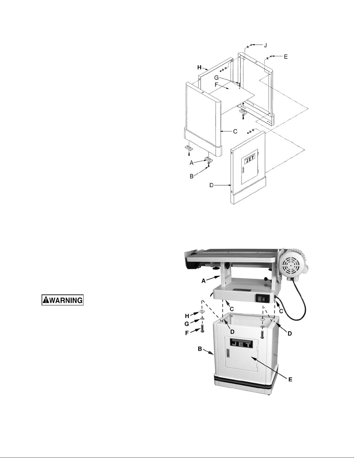
Stand Assembly
Referring to Fi gur e 1:
1. Remove all contents from the shipping
container.
2. Clean all rust protected surfaces with a mild
solvent. Do not use paint or lacquer thinner,
gasoline, or mineral spirits; these will damage
painted surfaces.
3. Attach the four rubber pads (A) to the bottoms
of the side panels (C) with four each
5/16” x 5/8” screws, 5/16” flat washers and
5/16” hex nut s (B). The hardware can be found
in the bag with the rubber pads.
4. Attach the side panels (C) to the front panel (D)
with four 5/16” x 5/8” hex cap screws, eight
5/16” flat washers, four 5/16” lock washers, and
four 5/16” hex nuts (E). Hand tighten the
hardware at this point.
Note: Assemble the stand upside down to
make sure that the tops of t he panels are flush.
5. Mount the shelf (F) to the inside of the stand
with two M5x10 pan head screws, two M5 flat
washers and two M5 lock washers (G).
Figure 1
6. Finish the stand a s sembly by attac hing the rear
panel (H) to side panels (C) with four
5/16” x 5/8” hex cap screws, eight 5/16” flat
washers, four 5/16” lock washers, and four
5/16” hex nut s (J).
7. Make sure stand is sitting evenly on a level
surface befor e tightening hardware.
Installing Table and Motor Unit to Stand
The Table and Motor Unit is
heavy! Use great care and adequ ate resources
when lifting the unit up onto the stand! Failure
to comply may cause serious injury and/or
damage to the sander and/or property!
Referring to Fi gur e 2:
1. With t he aid of another person, caref ully lif t the
table and motor unit (A) out of the shipping
box, and up onto the stand (B).
2. Li ne up threaded hol es i n the base (C) with the
holes in the stand (D).
3. Open the cabinet door (E) and through the
opening attach main unit to stand with two
5/16” x 1-1/4” hex cap screws (F), two 5/16”
lock washers (G) and two 5/16” flat
washers (H). Tight en with a 12mm wrench.
Figure 2
8
Page 9

Referring to Fi gur e 3:
4. The sanding platen (A) is presently in the
horizontal positi on. Pull lock handle (B) forward
to unlock the plat en assembly.
5. Tilt sanding platen to the vertical position (C),
which will look like D in Fig. 4; then push the
lock handle (B) to loc k the platen assembly in
place.
Note: Do not turn the l ock handle. Turning or
rotating the lock handl e will change the tension
of the locking assembly. This may cause the
locking assembly not to work, making it
necessary for adjustment before using the
machine.
Figure 3
Sanding Belt Installation
Referring to Fi gur e 5:
1. From the rear of the sander, remove the belt
guard (A) by unscrewing two lock knobs (B).
Take out the sanding belt and r emovable f ence
from behind the belt guar d.
2. Place the handle (C) on belt tensioning
lever (D). Remove the tension from the
mechanism by moving the handle (C) to the
Loose position.
3. Place belt on both roll ers so that the edge of
the belt is even wit h the edge of the rollers.
Note: Make sure that direction arrow on belt
matches the direction indicator on the top of
the platten.
4. Tighten the belt by moving the tension arm
handle (C) to the Tight po sit ion. Rot ate the bel t
by hand in the di rection indicated by t he arrow
on top of t he platten. If the bel t tracking needs
adjustment, see Belt Tracking Adjustment on
page 13.
Figure 4
Figure 5
9
Page 10

Drum Guard & Dust Port
Referring to Fi gur e 6:
Mounting the Drum G uard & Dust Port (referred to
below as drum guard)
1. Insert f our M4x20 f lat head screws (A) t hrough
the two hinges (B) of the drum guard (C). T hen
place two rectangular spacers (D) on the
threaded ends of t he screws.
Note: Orient the spacers so the slightly
rounded side sits against the hinge and the
edge farther f rom the screws lines up with the
edge of the hinge.
2. Secure the drum guard (A) to the belt guard on
the rear side of the sander by threading the
screws through the mounting holes (E) in the
belt guard. Tighten the screws.
Mounting the Connect ion P late
3. Place the drum guard (C) in the cl osed positi on
– this will cover t he dr iv e drum (J).
Note: You may have to slightly lift the cover
when closing i n order to clear the motor case.
This is normal.
4. Place washers (G) on two smal l lock knobs (H)
and then insert the threaded end of one lock
knob through the slot of the connection
plate (F) and the other lock knob through the
hole of the connect ion plate.
Figure 6
5. Secure the slotted side of the extension plate
to the drum guard (C) and the side with the
hole to the belt guard (E).
When repositi oning the dr um guard, sli ghtly l oosen
both lock knobs, open or close the cover, then
secure the lock k nobs.
Extension Table
Referring to Fi gur e 7:
1. Attach the bracket (E) for the extension t able to
the side of the motor housing (D) and secure
with two socket head cap screws (F).
2. Slide the shaft of the extension table (C) into
the bracket (E), positioning the table so the
opening (B) wraps around the drive dr um (A).
3. Insert lock knob (G) into the threaded hol e on
the side of t he bracket (E) v isibl e from t he rear
of the sander.
Figure 7
10
Page 11

Electrical
Grounding Instructions
This sander must be
grounded while in use to
protect the operat or from electric shock.
The temporary adapter should only be u sed until
a properly grounded outl et can be instal led by a
qualified electrician. This adapter is not
applicable in Canada. The green colored rigi d
ear, lug, or tab, extending from the adapter,
must be connect ed to a permanent ground such
as a properly grounded outlet box.
In the event of a malfunction or breakdown,
grounding prov i des a path of least resistanc e f or
electric current to reduce the risk of electric
shock. This tool is equipped with an electric
cord having an equipment-grounding conductor
and a grounding plug. The plug must be
plugged into a matching outlet that is properly
installed and grounded in accordance with all
local codes and ordinanc es.
Do not modify the plug provided. If it will not fi t
the outlet , have the proper outlet i nstalled by a
qualified el ectrician. Improper connecti on of the
equipment-grounding conductor can result in a
risk of electric shock. The conductor, with
insulati on having an outer surf ace that is green
with or without y ellow stripes, is the equipment grounding conduct or. If repai r or replac ement of
the electric cord or plug is necessary, do not
connect the equipment-grounding conductor to a
live terminal.
Check with a qualified electrician or service
personnel if the grounding instructions are not
completely understood, or if in doubt as to
whether the tool i s proper ly grounded. U se onl y
three wire ex tension cords that have thr ee- pr ong
grounding plugs and t hree-pole recept acles that
accept the tool ’s pl ug.
Repair or replace a damaged or worn cord
immediately.
230 Volt Operation
Referring to Fi gur e 9:
If 230V, single-phase operation is desired, the
following inst r uc tions must be followed:
1. Disconnect the machine from the power
source.
2. The JET O sci llati ng Edge Sander m ot or has
four numbered leads that are factory
connected f or 115V operation, as sho wn in
(A). For 230V operation reconnec t the l eads
as shown in (B).
3. The 115V att achment pl ug (C) supplied wit h
the Oscillating Edge Sander must be
replaced with a UL/ CSA listed plug sui table
for 230V operation (D). Contact your local
Authorized JET Service Center or qualified
electrician for proper procedures to install
the plug. T he Oscill ating E dge Sander must
comply wit h all loc al and national codes after
the 230-volt plug is installed.
4. The Oscil lating E dge Sander with a 230-v olt
plug should only be connected to an outlet
having the same configuration as shown in
(D). No adapter is available nor should be
used with the 230-volt plug.
115 Volt Operation
Referring to Fi gur e 8:
As received from the factory, your Oscillating
Edge Sander is ready to run at 115-volt
operation. This Oscillating Edge Sander, when
wired for 115 volt, is i ntended for use on a circuit
that has an outlet and a pl ug that looks like the
one illustrated in (A). A temporary adapter,
which looks li ke the adapter shown in (B), may
be used to connect this plug to a two-pole
receptacle if a properly grounded outlet is not
available.
Figure 8
Figure 9
11
Page 12

Extension Cords
Make sure your extension cord is in good
condition. When using an ex tension cord, be sure
to use one heav y enough to car ry the curr ent your
machine will draw. An undersized cord will cause
a drop in the line voltage resulting in power loss
and overheati ng. Table 1 sho ws the cor rect si ze t o
use depending on t he cord length and namepl ate
ampere rating. If in doubt, use the next heavier
gauge. Remember, the sm aller the gauge number,
the heavier the cor d.
Recommended Extension Cord Gauges
Extension Cord Length in Feet *
Amps
25 50 75 100 150 200
< 5 16 16 16 14 12 12
5 to 8 16 16 14 12 10 NR
8 to 12 14 14 12 10 NR NR
12 to 15 12 12 10 10 NR NR
15 to 20 10 10 10 NR NR NR
21 to 30 10 NR NR NR NR NR
Adjustments
Sanding Platen Angle Adjustment
Referring to Fi gur e 10:
1. Disconnect the machine from the power
source.
2. Pull the lock handle (B) forward (unlock) to
release tension.
Move the sanding platen (A) to the desired
position. Use a combination square between
the table and sanding platen to get precise
angles.
3. Hold the platen (A) while locking the handle.
Platen Lock Tension Adjustment
*based on li miting th e lin e voltag e drop to 5V at 150% of th e
rated amp eres.
NR: Not Recommended.
Table 1
Figure 10
1. Disconnect the machine from the power
source.
2. Loosen (unlock) the handle (B, Fig. 10) and
place the platen in the horizontal position as
shown in (A, Fig. 10). Do not loc k.
3. Tensi on eccent ric bl ock by tighteni ng the nyl on
nut (B, Fi g. 11) with a 14mm wrench. Turn t he
nut in by 1/4 t urn increments and test locki ng
handle for proper tension.
The lock handle is properl y tensioned when it
requires positive force to move the eccentric
block (at tached to the locki ng handle) from one
side to the other. The platen and motor
assembly must stay in a locked position
without sliding once the handle has been
moved to the locked position. Re-adjust as
necessary.
Figure 11
12
Page 13

Changing the Sanding Belt
Referring to Fi gur e 12:
1. Disconnect the machine from the power
source.
2. Lock the sandi ng platen i n the v ertical posit ion
(see the Sanding Platen Angle Adjustment
section on page 12).
3. Release tension on the belt by loosening the
handle (C).
4. Loosen or remove the lock knobs (B) and
remove the belt guar d (A).
5. Remove the old belt and install the new belt
matching the direction of the arrows on the belt
with the arrow label on t he top of the platen.
6. Line up edge of belt with edge of r oller s.
7. Place tension on the belt by moving the
tension arm handle (C) to the Tight position.
8. Reinstall the belt guard (A) and tighten t he lock
handles (B)
Note: Belts stretch with wear. When a belt is
replaced, y ou m ay have to adj ust trac king.
Belt Tracking Adjustment
The B elt Tracking Adjustment is a f ine adj ustment
procedure. The M otor Mount Tracking Adjustment
(following section) is a course adjustm ent.
Figure 12
To adjust the belt t r acking:
1. Disconnect the machine from the power
source.
2. Push the belt by hand from left to right (the
direction indicated top of the platen) and
observe the bel t’s position on the rol lers. The
oscillating movement of the belt is by design.
Observe the belt 's range of m ovement from it s
highest to lowest position. The edges of the
belt should not have a tendency to move
above or below the edges of the rollers.
If adjustm ent is still nec essary :
3. Insert t he round shaft of t he belt tracking tool
(provided) into the micro adjust lock nut (A)
and turn away from you to loosen.
4. Turn the micr o adjusting screw (B) i n 1/4 turn
increments until the belt tracks evenly on the
roller s when rotated by hand.
Tip: Moving the belt tracking tool away from
you raises the belt on the drum and towards
you lowers the belt on the drum.
5. Tighten the mic r o adjusting nut (A).
Figure 13
6. Connect the machine to power.
7. Turn on the po wer to the m achine and ob serv e
the belt’s up and down range of m ov em ent.
Adjustment is correct when the edges of the
belt do not m ove above or below the edge s of
the rollers.
8. W hen adjustm ent is com plete, ti ghten t he micro
adjust lock nut (A).
If the tracki ng cannot be corrected go to the Motor
Mount Track ing Adjust m ent section (next page).
13
Page 14

Motor Mount Tracking Adjustment
Referring to Fi gur e 14:
The OES-80CS comes with tracking adjustment
bolts (A) on t he motor pl ate. These are set at t he
factory and should not require any further
adjustment. If, howev er, you are not abl e to track
the belt with the Belt Tracking Adjustment
described in t he prev i ous section, the m ot or mount
bolts will have to be adjusted.
Note: The Motor Mount Tracking Adjustment is a
course adjustment. Use the Belt Tracking
Adjustment first for fine adjustment. If it cannot be
adjusted, then use the procedure described below.
To adjust:
1. Disconnect the machine from the power
source.
2. Slightly loosen the four motor mount nuts (B)
just enough so the tracking screws (A) can be
turned to make an adjustm ent.
3. Loosen the two locking hex nuts (C) that
secure the tracking screws (A).
4. Turn one screw (A) a 1/4 turn and rotate the
sanding belt by hand to observe which
direction t he adjustment i s causing the belt t o
move. If it is trav eling i n the direction needed
to correctl y tr ac k the belt go t o st ep 6.
5. If the bel t starts to tr avel in t he wrong di r ec tion,
back off a quarter turn and tighten the other
screw a quar ter tur n. Thi s should start t he belt
moving in the proper direction.
6. Tighten both loc king nut s (C) and m otor m ount
nuts (B). Then return to the Belt Tracking
Adjustment sect ion (previous page) and again
attempt to fine tune the tracking.
Figure 14
Table Adjustment
Do not position table below
sanding belt! Keep an overlap of at least 1/16”
between table and sanding belt to avoid
material and/or fingers getting caught! Failure
to comply may cause seriou s injury!
1. Loosen two lock knobs (A, Fig. 15).
2. Raise or lower work table to desired level.
3. Tighten two lock knobs.
Figure 15
14
Page 15

Basic Operations
Removing the belt guard
exposes more o f the sandi ng bel t! Repl ace th e
belt guards immediately after completing any
sanding that requires its removal! Failure to
comply may cause seriou s injury!
Horizontal Sanding
For hor izontal sanding, the platen is locked in the
horizontal posi tion as shown (F) and the removable
fence (D) is secured to the table (E) as follows.
Referring to Fi gur e 16:
1. Place 5/16 flat was hers ( not shown) and guide
blocks (B) on two 12mm lock knobs (A) – Note:
the 12mm refers to the threaded shaft length.
2. Insert the guide blocks (B) into the miter slot
(C) and position the lock knobs (G) on the
table (E) as shown.
3. Place the removable fence (D) on the table
and secure by tightening the lock knobs
(G, Fig. 16 and Figure 17).
Figure 16
The backstop (H, Fig. 17) can also be used by
swiveling the drum guard & dust port (J, Fig. 17)
out of the way and plac ing the backstop pi n in the
positioni ng hol e and securing in plac e with t he lock
knob (K, Fig. 17) and 5/16" flat washer . Note: This
is better shown in Figure 18. The drum guard &
dust port (J, Fig. 17) can then be returned to the
position shown.
Vertical Sanding
Referring to Fi gur e 18:
For vertical sanding, the platen (G) is locked in the
vertical position as shown and the backstop (H)
and/or the mit er gauge (B) m ay be used.
Miter Gauge
1. Slide the guide bar ( D) of the miter gauge (A)
into the miter slot (C) on the table.
Figure 17
2. Set the miter angle; then secure the mi ter by
tightening the lock handle (B).
Backstop
Place the back stop pin in the po sitioni ng hole and
secure in place with the lock knob (E) and 5/16"
flat washer (F).
Figure 18
15
Page 16

Contour Sanding
Referring to Fi gur e 19:
Contour sanding is done f rom the extension table
mounted on the motor where the sanding belt
wraps around the drive drum (D). To set up the
sander for cont our sandi ng:
1. Loosen the t wo lock knobs (C) that secure the
drum guard & dust port (E).
2. Swing the end guard (E) back, bringing the
drive drum (D) into view.
3. Tighten the loc k k nobs (C).
4. Mount the extens ion t able (A) to the sander by
inserting the post (B) into the bracket (F).
5. Set the table to the desir ed height, then secure
into positi on by tightening the lock knob (G).
Important: When the extension t able (B) is not in
use, the drum guard & dust port (E) should always
be in the closed posi tion so the drive drum (D) is
not in view.
Figure 19
16
Page 17

Troubleshooting Operating Problems
Trouble Possible Cause Solution
Sander will not star t
Sanding belt does
not come up to speed
Machine vibrates
excessively
Abrasive belt keeps
tearing
Sanded edge not
square
1. Sander unplugged from
wall or motor
2. Fuse blown or circuit
breaker tripped
3. Cord damaged
1. Extension cord too light
or too long
2. Motor not wired for
proper voltage
3. Low current
1. Stand on uneven floor
2. Motor mounts are loose
3. Tension spring i s worn
or broken
1. Belt is runni ng in the
wrong directi on
1. Table not square to
sanding platen
1. Check all plug connections
2. Replace fuse or reset circuit breaker
3. Replace cord
1. Replace with adequat e si z e and length
cord (see Recommended Extension
Cord Gauges on page 12)
2. Refer to motor junction cover for proper
wiring
3. Contact a qualified electrician
1. Adjust stand so that it r ests evenly on the
floor
2. Tighten motor mount bolts
3. Replace spring
1. Arrow on the sanding belt and m ac hine
should be pointing in the same direction.
1. Use a square to adjust table to sanding
platen
Sanding marks on
wood
1. Wrong grit sanding belt
2. Feed pressure too great
3. Sanding against the
grain
1. Use coarser grit for stoc k removal and
fine grit for finish sanding.
2. Never force work i nto sanding platen
3. Sand with the grain
Parts
Ordering Replacement Parts
To order parts or reach our service department, call 1-800-274-6848 Monday through Friday (see our
website for business hours, www.jettools.com). Having the Model Number and Serial Number of your
machine available when you call will allow us to serve you quickly and accurately.
17
Page 18

Table and Motor – Assembly
18
Page 19

Table and Motor – Parts
Index No. P art No. Descri ption Size Qty.
1 ............... EHVS80 CS-01 .........Ba se ...................................................................................................... 1
2 ............... EHVS80-02N ...........Push Button Switch ............................................................................... 1
3 ............... EHVS80 -03N ...........Switch Panel ......................................................................................... 1
4 ............... TS-081C082 ............Pan Head Screw ................................................#10-24×1-1/2” ............. 3
5 ............... EH VS8 0-0 2B ...........Sw itch Box .............................................................................. .............. 1
6 ............... TS-0560071 .............Hex Nut ..............................................................#10-24 ........................ 5
7 ............... EHVS80 -07 ..............Strain Relie f ........................................................................................... 2
8 ............... EHVS80-08 ..............Work Tab le Ba r ..................................................................................... 1
9 ............... EHVS80-09A ...........Nylon Insert Lock Nut .........................................3/8”-24........................ 1
10 ............. EHVS80-10 ..............Locking Block ........................................................................................ 1
11 ............. EHVS80-11 ..............Spring Pin...........................................................∅4 .............................. 1
12 ............. EHVS80-12 ..............Lock Handle .......................................................... ................................ 1
13 ............. 10102023A ..............Knob ..................................................................................................... 1
................. EHVS80 -12A ...........Lock Handle Assembly
14 ............. S0430525 ................Key.....................................................................5×5×25 ....................... 1
15 ............. TS-0050031 .............Hex Cap Screw ..................................................1 /4 ” -2 0 ×3 /4 ”................ 1
16 ............. TS-0680021 .............Flat Washe r ........................................................1/4”............................. 5
17 ............. EHVS80-17 ..............Table ..................................................................................................... 1
18 ............. EHVS80 -18 .............Screw .................................................................M10 ............................ 2
19 ............. TS-1540071 .............Hex Nut ..............................................................M10 ............................ 2
20 ............. EHVS80-20 ..............Guide Block ........................................................................................... 2
21 ............. EHVS80-21 ..............Fence .................................................................................................... 1
22 ............. EHVS80-22A ...........JET Knob ...........................................................M8×12 mm .................. 3
23 ............. OES80CS-23 ...........D rive Drum (
serial no. 05110394 and higher) .............................................. 1
24 ............. EHVS80-24 ..............Guide Bar .............................................................................................. 1
25 ............. S0310306 ................Pin......................................................................∅3 .............................. 1
26 ............. TS-0267021 .............Set Screw ...........................................................1/4”-20×1/4”................ 1
27 ............. EHVS80-27 ..............Location Plate........................................................................................ 1
28 ............. EHVS80-28 ..............Pointer................................................................................................... 1
29 ............. ................................Sanding Belt (local purc hase) .............................6”W x 89”L.................. 1
30 ............. 10104046 .................Miter Gauge Body.................................................................................. 1
................. EHVS80 -MG ............Miter Gauge Assembly
31 ............. TS-081B042.............Pan Head Screw ................................................#8-32×5/8” .................. 3
32 ............. TS-0560061 .............Hex Nut ..............................................................#8-32 .......................... 3
33 ............. EHVS80-33 ..............Knob ..................................................................................................... 1
34 ............. 20101048 .................Platen .................................................................................................... 1
35 ............. OES80CS-135 .........Side Plate .............................................................................................. 1
................. TS-0051061 .............Hex Cap Screw (m otor plate-not shown) ..........5/16”-18×1-1/4”........... 2
................. TS-0561021 .............Hex Nut (motor plate-not shown) ......................5/16”-18 ...................... 2
36 ............. EHVS80-36A ...........JET Knob ...........................................................M8×35 mm .................. 1
37 ............. EHVS80-37A ...........Pin......................................................................∅6×40mm .................. 1
38 ............. TS-0561011 .............Hex Nut ..............................................................1/4”-20........................ 2
39 ............. EHVS80-39A ...........Spacer................................................................................................... 1
40 ............. TS-0733031 .............External Tooth Lock Washer ...............................#10 ........................... 11
41 ............. EHVS80-28A ...........Location Block ....................................................................................... 1
42 ............. TS-0561031 .............Hex Nut ..............................................................3/8”-16........................ 1
43 ............. TS-0051021 .............Hex Cap Screw ..................................................5 /1 6 ” -1 8 ×5 /8 ” .............. 4
44 ............. TS-0720091 .............Lock Washer ......................................................3/8”............................. 2
45 ............. EHVS80-49 ..............Washer Head Scr ew ...........................................#10-24 x 3/8” .............. 3
46 ............. EHVS80-57 ..............Tilt Scale ............................................................................................... 1
47 ............. TS-081C052 ............Pan Head Screw ................................................#10-24x3/4” ................ 1
48 ............. EHVS80-59 ..............Pointer................................................................................................... 1
49 ............. TS-081C022 ............Pan Head Screw ................................................#10-24x3/8” ................ 2
50 ............. OES80CS-150 .........Motor ..................................................................1 -1/2HP, 1PH ............. 1
51 ............. TS-0051061 .............Hex Cap Screw ..................................................5 /1 6 ” -1 8 x1- 1 /4 ” ........... 5
(index #12,13) ..................................................... 1
(index #20,24-28,30-33,41) .................................... 1
19
Page 20

Table and Motor – Parts
Index No. P art No. Descri ption Size Qty.
52 ............. TS-0680031 .............Flat Washe r ........................................................5/16” ......................... 10
53 ............. OES80CS-153 .........Pin......................................................................................................... 2
54 ............. EHVS80-67 ..............Motor Cord ............................................................................................ 1
55 ............. OES80CS-155 .........Dust Port ............................................................................................... 1
56 ............. OES80CS-156 .........Sanding Belt Cover ................................................................................ 1
57 ............. EHVS80-70A ...........Up-Down Table Mount Plate .................................................................. 2
58 ............. EHVS80-71A ...........JET Knob ...........................................................M8X20mm .................. 4
59 ............. EHVS80-72 ..............Back Stop Bracket ................................................................................. 1
60 ............. TS-0720081 .............Lock Washer ......................................................5/16” ......................... 14
61 ............. TS-0561021 .............Hex Nut ..............................................................5/16”-18 ...................... 6
62 ............. TS-0051061 .............Hex Cap Screw ..................................................5 /1 6 ” -1 8 x1- 1 /4 ” ........... 2
63 ............. TS-2285121 .............Flat Head Screw .................................................M5x12 ........................ 8
64 ............. TS-2284201 .............Flat Head Screw .................................................M4x20 ........................ 8
65 ............. EHVS80-94 ..............Extension Table ..................................................................................... 1
66 ............. EHVS80-96 ..............Supporting Rod ..................................................................................... 1
67 ............. EHVS80-57A ...........Tilt Angle Scale Label ............................................................................ 1
68 ............. EHVS80-108 ............Direction Label ...................................................................................... 1
69 ............. EHVS80-107 ............Warning Label ...................................................................................... 1
70 ............. EHVS80-68 ..............Power Cord ........................................................................................... 1
71 ............. OES80CS-171 .........Hinge .................................................................................................... 2
72 ............. OES80CS-172 .........Knob ..................................................................M6 .............................. 2
73 ............. OES80CS-173 .........Supporting Seat ..................................................................................... 1
74 ............. TS-0206041 .............Socket Head Cap Screw .....................................#10-24x3/4” ................ 2
75 ............. OES80CS-175 .........Spacer................................................................................................... 2
76 ............. EHVS80-34G ...........Graphite Pad ......................................................................................... 1
77 ............. EHVS80-51 ..............Belt Tension Arm ................................................................................... 1
78 ............. EHVS80-54 ..............Tension Arm Handle .............................................................................. 1
79 ............. OES80CS-
80 ............. EHVS80-111 ............Drum Guard .......................................................................................... 1
81 ............. OES80CS-181 .........ID Label ................................................................................................. 1
82 ............. OES80CS-182 .........Hinge Bracket ........................................................................................ 2
179 .........Connecti on Pl ate ................................................................................... 1
20
Page 21

Idle Drum – Assembly
21
Page 22

Idle Drum – Parts
Index No. P art No. Descri ption Size Qty.
................. OES80CS-IDRA.......Idle Drum Complete Assembly
1 ............... OES80CS -201 .........Tension Bar ........................................................................................... 1
2 ............... OES80CS -203 .........S pring.................................................................................................... 1
3 ............... TS-0561021 .............Hex Nut ..............................................................5/16” ........................... 1
13 ............. TS-1523011 .............Socket Set Screw ...............................................M6x6 .......................... 2
15 ............. S0400545 ................K ey.....................................................................5x5x45m m.................. 1
16 ............. OES80CS-216 .........Worm .................................................................................................... 1
17 ............. OES80CS-217 .........Spacer................................................................................................... 1
18 ............. S0400425 ................K ey.....................................................................4 x4x25 ....................... 1
19 ............. TS-0640081 .............Nylon Insert Lock Nut .........................................5/16” ........................... 6
20 ............. TS-0680031 .............Flat Washe r ........................................................5/16” ........................... 4
22 ............. TS-0720081 .............Lock Washer ......................................................5/16” ........................... 6
23 ............. TS-2342141 .............Nylon Insert Lock Nut .........................................M14 ............................ 2
24 ............. OES80CS-224 .........Bracket .................................................................................................. 1
25 ............. TS-0050031 .............Hex Cap Screw ..................................................1 /4 ” -2 0 x3/4 ” ................ 2
26 ............. OES80CS-226N.......Lead Screw ........................................................................................... 1
27 ............. OES80CS-227 .........Spring.................................................................................................... 1
28 ............. OES80CS-228 .........Ball Bearing ........................................................698 ............................. 3
29 ............. OES80CS-229 .........Retaining Ring ....................................................STW-8 ........................ 1
30 ............. TS-1502051 .............Socket Head Cap Screw .....................................M5x20 ........................ 2
31 ............. TS-0208061 .............Socket Head Cap Screw .....................................5/16”x1” ...................... 1
32 ............. TS-2284121 .............Flat Head Screw ................................................M4x12 ....................... 3
34 ............. BB-6202VV ..............Ball Bearing ........................................................6202LLU .................... 2
35 ............. OES80CS-235 .........Bearing Housing .................................................................................... 1
36 ............. BB6003ZZ ...............Ball Bearing ........................................................6003ZZ....................... 1
37 ............. S0400430 ................K ey.....................................................................4 x4x30 ....................... 1
38 ............. OES80CS-238 .........Gear Housing ........................................................................................ 1
39 ............. TS-1502021 .............Socket H
40 ............. OES80CS-240 .........Bushing ................................................................................................. 2
41 ............. OES80CS-241 .........Cam ...................................................................................................... 1
42 ............. OES80CS-242 .........Worm Gear ............................................................................................ 1
43 ............. OES80CS-243 .........Worm Gear Shaft................................................................................... 1
44 ............. OES80CS-244 .........Column.................................................................................................. 2
48 ............. TS-0051081 .............Hex Cap Screw ..................................................5 /1 6 ” -1 8 x1- 3 /4 ” ........... 1
49 ............. TS-1551031 .............Lock Washer ......................................................M5 .............................. 6
50 ............. OES80CS-250 .........Rod ....................................................................................................... 1
52 ............. EHVS80-81 ..............Belt Tracking Tool.................................................................................. 1
53 ............. TS-0810012 .............Round Head Sl otted Machine Screw...................#10-24x1/4” ................ 4
54 ............. OES80CS-254 .........Self Tapping Screw ............................................M3 x6 .......................... 1
55 ............. OES80CS-255 .........Dust Hood (Left) .................................................................................... 1
56 ............. OES80CS-256 .........Dust Hood (Right) .................................................................................. 1
57 ............. OES80CS-257 .........Ring ...................................................................................................... 2
58 ............. OES80CS-258 .........Wave Washer ........................................................................................ 2
59 ............. OES80CS-259 .........Idle Drum .............................................................................................. 1
60 ............. OES80CS-260 .........Track Adjustin g Block ............................................................................ 1
61 ............. OES80CS-261 .........Drive Shaft ............................................................................................ 1
62 ............. OES80CS-262 .........Button Head Socket Screw .................................5/16 ”X 1-3 /4 ................ 2
63 ............. OES80CS-263 .........Guard .................................................................................................... 1
65 ............. OES80CS-265 .........Foam Sheet for Drive Shaft ................................................................... 1
66 ............. OES80CS-266 .........Idle Drum Bracket .................................................................................. 1
67 ............. OES80CS-267 .........Track Adjusting Screw ........................................................................... 1
68 ............. OES80CS-268 .........Track Adjusting Nut ............................................................................... 1
69 ............. OES80CS-269 .........Retaining Ring ....................................................S10 ............................ 1
70 ............. OES80CS-270 .........Bearing Housing .................................................................................... 1
71 ............. OES80CS-271 .........Foam Sheet for Lead Screw .................................................................. 1
72 ............. OES80CS-272
.........Cone Disc Spring................................................................................... 2
ead Cap Screw .....................................M5x10 ........................ 5
(index # 1-72) .......................................... 1
22
Page 23

Stand Assembly
Index No. P art No. Descri ption Size Qty.
1 ............... TS-0680031 .............Flat Washe r ........................................................5/16” ......................... 22
2 ............... TS-0720081 .............Lock Was h e r ......................................................5/16” ......................... 10
3 ............... TS-0561021 .............Hex Nut ..............................................................5/16”-18 ...................... 8
4 ............... EHVS80 CS-S04.......Side Panel ............................................................................................. 2
5 ............... EHVS80 CS-S05.......Pad ....................................................................................................... 4
6 ............... EHVS80 CS-S06.......Screw .................................................................................................... 4
7 ............... EHVS80 CS-S07.......Rear Panel ............................................................................................ 1
8 ............... TS-0561021 .............Hex Nut ..............................................................5/16”-18 ...................... 4
9 ............... TS-0051061 .............Hex Cap Scr e w ..................................................5/16” -1 8 x1- 1 /4 ” ........... 2
10 ............. TS-1533032 .............Pan Head Screw ................................................M5x10 ........................ 2
11 ............. EHVS80CS-S11.......D oor ...................................................................................................... 1
12 ............. EHVS80CS-S12.......Shelf ...................................................................................................... 1
13 ............. EHVS80CS-S13.......L atch Assembly ..................................................................................... 1
14 ............. TS-1551031 .............Lock Washer ......................................................M5 .............................. 2
15 ............. EHVS80CS-S15.......Front Panel (W/Door)............................................................................. 1
16 ............. EHVS80CS-S16.......Screw .................................................................................................... 2
17 ............. EHVS80CS-S17.......JET Label .............................................................................................. 1
18 ............. TS-1550031 .............Flat Washe r ........................................................M5 .............................. 2
19 ............. TS-0081031 .............Hex Cap Screw ..................................................5 /1 6 ” -1 8 x3/4 ” .............. 8
................. STRIPE-1-3 /4 ..........JET Str ipe (no t show n ) .......................................1-3/4”w ................ per ft.
23
Page 24

Wiring Diagram
24
 Loading...