

Page 1

This .pdf document is bookmarked
Operating Instructions and Parts Manual
14-inch Woodworking Band Saw
Model JWBS-14CS
JET
427 New Sanford Road
LaVergne, Tennessee 37086 Part No. M-708115
Ph.: 800-274-6848 Revision D 02/2014
www.jettools.com Copyright © 2014 JET
Page 2

Warranty and Service
JET warrants every product it sells against manufacturers’ defects. If one of our tools needs service or repair, please
contact Technical Service by calling 1-800-274-6846, 8AM to 5PM CST, Monday through Friday.
Warranty Period
The general warranty lasts for the time period specified in the literature included with your product or on the official
JET branded website.
• JET products carry a limited warranty which varies in duration based upon the product. (See chart below)
• Accessories carry a limited warranty of one year from the date of receipt.
• Consumable items are defined as expendable parts or accessories expected to become inoperable within a
reasonable amount of use and are covered by a 90 day limited warranty against manufacturer’s defects.
Who is Covered
This warranty covers only the initial purchaser of the product from the date of delivery.
What is Co vered
This warranty covers any defects in workmanship or materials subject to the limitations stated below. This warranty
does not cover failures due directly or indirectly to misuse, abuse, negligence or accidents, normal wear-and-tear,
improper repair, alterations or lack of maintenance.
Warranty Limitations
Woodworking products with a Five Year Warranty that are used for commercial or industrial purposes default to a
Two Year Warranty. Please contact Technical Service at 1-800-274-6846 for further clarification.
How to Get Technical Support
Please contact Technical Service by calling 1-800-274-6846. Please note that you will be asked to provide pro of
of initia l p u rch a s e whe n calling. If a product requires further inspection, the Technical Service representative will
explain and assist with any additional action needed. JET has Authorized Service Centers located throughout the
United States. For the name of an Authorized Service Center in your area call 1-800-274-6846 or use the Service
Center Locator on the JET website.
More Informa t io n
JET is constantly adding new products. For complete, up-to-date product information, check with your local distributor
or visit the JET website.
How S tate Law Applies
This warranty gives you specific legal rights, subject to applicable state law.
Limitations on This Warranty
JET LIMITS ALL IMPLIED WARRANTIES TO THE PERIOD OF THE LIMITED WARRANTY FOR EACH PRODUCT.
EXCEPT AS STATED HEREIN, ANY IMPLIED WARRANTIES OF MERCHANTABILITY AND FITNESS FOR A
PARTICULAR PURPOSE ARE EXCLUDED. SOME STATES DO NOT ALLOW LIMITATIONS ON HOW LONG AN
IMPLIED WARRANTY LASTS, SO THE ABOVE LIMITATION MAY NOT APPLY TO YOU.
JET SHALL IN NO EVENT BE LIABLE FOR DEATH, INJURIES TO PERSONS OR PROPERTY, OR FOR
INCIDENTAL, CONTINGENT, SPECIAL, OR CONSEQUENTIAL DAMAGES ARISING FROM THE USE OF OUR
PRODUCTS. SOME STATES DO NOT ALLOW THE EXCLUSION OR LIMITATION OF INCIDENTAL OR
CONSEQUENTIAL DAMAGES, SO THE ABOVE LIMITATION OR EXCLUSION MAY NOT APPLY TO YOU.
JET sells through distributors only. The specifications listed in JET printed materials and on official JET website are
given as general information and are not binding. JET reserves the right to effect at any time, without prior notice,
those alterations to parts, fittings, and accessory equipment which they may deem necessary for any reason
whatsoever. JET
Product Listing with Warranty Period
90 Days – Parts; Consumable items; Light-Duty Air Tools
1 Year – Motors; Machine Accessories; Heavy-Duty Air Tools; Pro-Duty Air Tools
2 Year – Metalworking Machinery; Electric Hoists, Electric Hoist Accessories; Woodworking Machinery used
for industrial or commercial purposes
5 Year – Woodworking Machinery
Limited Lifetime – JET Parallel clamps; VOLT Series Electric Hoists; Manual Hoists; Manual Hoist
Accessories; Shop Tools; Warehouse & Dock products; Hand Tools
NOTE: JET is a division of JPW Industries, Inc. References in this document to JET also apply to JPW Industries,
Inc., or any of its successors in interest to the JET brand.
®
branded products are not sold in Canada by JPW Industries, Inc.
2
Page 3

Table of Contents
Warranty and Servic e .............................................................................................................................. 2
Warning ................................................................................................................................................... 4
Introduction ............................................................................................................................................. 6
Specifica tions ................................................................................................................ .......................... 6
Unpacking – JWBS-14CS ........................................................................................................................ 7
Contents of the Shipping Container ...................................................................................................... 7
Fasteners ............................................................................................................................................. 7
Assembly of JWBS-14CS ........................................................................................................................ 8
Grounding Inst r uc tions ........................................................................................................................... 10
115 Volt Operati on ............................................................................................................................. 11
230 Volt Conversion ........................................................................................................................... 11
Extension Cords................................................................................................................................. 11
Adjustments .......................................................................................................................................... 12
Tilting th e Table ............................................................................................................. .................... 1 2
Adjusting 90° Table Stop .................................................................................................................... 12
Changing Blades ................................................................................................................................ 13
Adjusting Bl ade Tension ..................................................................................................................... 13
Adjusting Bl ade Trac ki ng .................................................................................................................... 13
Adjusting Upper Blade Guide Assembly ............................................................................................. 1 4
Adjusting Bl ade Guide and Blade Support Bearing ............................................................................. 14
Troubleshooting JWBS-14CS Band Saw ............................................................................................... 16
Optional Accessories ............................................................................................................................. 17
Replacement Parts ................................................................................................................................ 17
Parts List – Body Assembl y (JWBS-14CS Band Saw) ........................................................................ 18
Exploded View – Body Assembly (JWBS-14CS Band Saw) ................................................................ 20
Parts List – Closed Stand Assembly (JWBS-14CS Band Saw) ........................................................... 21
Exploded View – Closed Stand A ssembly (JWBS14-CS Band Saw) ................................................... 22
Electri c al Connec tions – 115 volt (JWBS-14CS Band Saw) .................................................................... 23
Electri c al Connec tions – 230 volt (JWBS-14CS Band Saw) .................................................................... 24
3
Page 4

Warning
1. Read and understand the ent ire owner’s manual befor e att em pting assembly or operation.
2. Read and understand the warnings po sted on the m achine and i n thi s manual. Fail ure to comply wit h
all of these warnings m ay cause seriou s i njury.
3. Replace the warning labels if they become obscured or removed.
4. This band saw is designed and i ntended for use by proper ly trained and ex per i enced personnel onl y.
If you are not familiar with the proper and safe operation of a band saw, do not use until proper
training and knowledge have been obtained.
5. Do not use this b and saw for ot her than its int ended use. If used for other pur poses, JET discl aims
any real or implied warrant y and holds itself harmless from any injury that may result fr om that use.
6. Always wear approved safet y glasses/face shields while using this band saw. Everyday eyegl asses
only have impact resi stant lenses; they are not safety glasses.
7. Before operating this band saw, remove tie, rings, watches and other jewelry, and roll sleeves up past
the elbows. Remove all loose clothing and c onfine long hair. Non-sli p footwear or anti-skid fl oor str ips
are recommended. Do not wear gloves.
8. Wear ear protector s (plugs or muffs) during ext ended peri ods of oper ation.
9. Some dust created by power sanding, sawing, grinding, drilling and other construction activities
contain chemi cals known to cause cancer , bir th defects or other r eproductiv e harm . Some exampl es
of these chemic als are:
• Lead from lead based paint.
• Crystalli ne sil ic a from bricks, cement and other m asonry pr oduc ts.
• Arsenic and chromium from chemically treated lumber .
Your risk of exposure varies, depending on how often you do this type of work. To reduce your
exposure to these chemicals, work in a well-ventilated area and work with approved safety
equipment, such as face or dust masks that are specifically designed to filter out microscopic
particles.
10. Do not operate this machi ne while tired or under the influence of drugs, alcohol or any medication.
11. M ak e c er tain the switch is in the OFF position before connecti ng the machine to the power supply.
12. M ak e c er tain the machine is properly grounded.
13. M ak e all machine adjustments or maintenance with the machine unplugged from the power source.
14. Remove adjusting keys and wrenches. Form a habit of checking to see that keys and adjusting
wrenches are removed from the machine before turning it on.
15. Keep safety guards in place at all times when the machi ne is in use. If removed for maintenance
purposes, use extreme caution and replace the guards immediately.
16. M ak e sure t he band sa w is firmly secured to the stand, or bench, before use.
17. Check damaged parts. Before further use of the machine, a guard or other part that is damaged
should be carefully checked to determine that it will operate properly and perform its intended
function. Chec k for alignment of moving par ts, binding of moving parts, breakage of parts, mounting
and any other condi ti ons that m ay affect its operati on. A guard or ot her part that i s damaged should
be properly repaired or replaced.
18. P r ov ide for adequate space surroundi ng work area and non-glare, ov er head l ighting.
19. K eep the floor around the machi ne cl ean and free of scrap material, oil and grease.
20. K eep v isitors a safe distance from the work area. Keep children away.
4
Page 5

21. M ak e y our workshop chi ld proof with padloc k s, m aster switc hes or by r em ov ing starter keys.
22. Giv e your work undivi ded attention. Looki ng around, carryi ng on a conversati on and “horse-play” ar e
careless acts that can r esul t in serious injury.
23. Maintain a balanced stance at all times so that you do not fall or lean against the blade or other
moving part s. Do not over r eac h or use excessive force to perform any mac hine oper ation.
24. Use the ri ght t ool at the corr ect speed and feed r ate. Do not forc e a tool or attachment to do a job for
which it was not designed. T he ri ght tool will do the job better and safer.
25. Use recom mended accessories; improper accessories may be hazardous.
26. Maintai n tools with care. Keep blade sharp and cl ean for the best and safest per formance. Follow
instructions for lubricating and changing accessories.
27. M ake sure the work piece i s held firml y against the rip f ence or miter gauge as it is fed through the
blade.
28. Turn off the m ac hine before cleaning. Use a brush or compressed air to rem ov e c hips or debris — do
not use your hands.
29. Do not stand on the machine. Seri ous i njur y c ould occur if the machine tips over.
30. Never leave the mac hine r unning unattended. Turn the power off and do not leav e the mac hine until it
comes to a complete stop.
31. Remove loose items and unnecessary work pieces from the area before starting the machine.
Familiariz e you rself with the following safety no tices used in this manual:
This means that if precautions are not heeded, it may result i n mi nor i nj ur y and/or
possible machine damage.
This means that if precautions are not heeded, it may result i n serious injury or possibly
even death.
- - SAVE THESE INSTRUCTIONS - -
5
Page 6

Introduction
This manual i s provided by JET covering the safe operati on and maintenance procedures f or a Model
JWBS-14CS Band Saw. This manual contains instructions on installation, safety precautions, general
operating proc edures, maintenance i nstructions and part s breakdown. This m achine has been designed
and constructed to pr ovi de years of troubl e free operation if used in accor dance wit h instructi ons set fort h
in this m anual. If there are any questi ons or com ments, please contact either y our local supplier or JET.
JET can also be reached at our web site: www.jettools.com.
Specifications
Model Number: .......................................................................................................................JWBS-14CS
Stock Number.............................................................................................................................. 708115K
Wheel Diameter (in.) .............................................................................................................................. 14
Cutting Capacity – Height/Resaw (in.) ...................................................................................................... 6
Cutting Capacity – Width (in.) .......................................................................................................... 13 -1/2
Minimum Blade Width (in.) .................................................................................................................... 1/8
Maximum Blade Width (in.) ................................................................................................................... 3/4
Blade Length (in.) ............................................................................................................................ 93-1/2
Blade Speed (SFPM ) ......................................................................................................................... 3000
Blade included ............................................................................................................................ 3/8”, 6TPI
Table Size (in.) ............................................................................................................................... 15 x 15
Table Slot Size (DxW/in.) .............................................................................................................. 3/8 x 3/4
Table He ight From Flo o r ( in.) ........................................................................................................... 43-1/2
Table Tilt (deg.) .................................................................................................................. 45 right, 10 left
Dust Port Diameter (in.) ........................................................................................................................... 4
Overall Dimensions (HxWxD/in.) ............................................................................................. 68 x 26 x 19
Motor ................................................................................................. 1HP, 1PH, 115/230V ( pr ewir ed 115)
Listed FLA (full load amps) ................................................................................................................. 10/5
Starting Am ps (@115V input) .............................................................................................................. 20A
Running Amps ........................................................................................................................ 7-8 / 3.5-4.0
Net Weigh t (lb s.) .................................................................................................................................. 185
Shipping Weigh t (lbs.) .......................................................................................................................... 19 7
The above specifications were current at the time this manual was publi shed, but because of our policy of
continuous impr ovement, JET reserves the ri ght to change specifications at any tim e and without pri or
notice, without incurring obligati ons.
6
Page 7
Unpacking – JWBS-14CS
Open both shippi ng container s and check for shippi ng damage. Report any damage im mediatel y to your
distribut or and shipping agent. Read the instructi on manual thoroughly for assembl y, maintenance and
safety instructions.
Contents of the Shipping Container
Container One:
1 Closed stand with motor
1 Pulley cover
1 V-belt
Container Two:
1 Saw body
1 Table
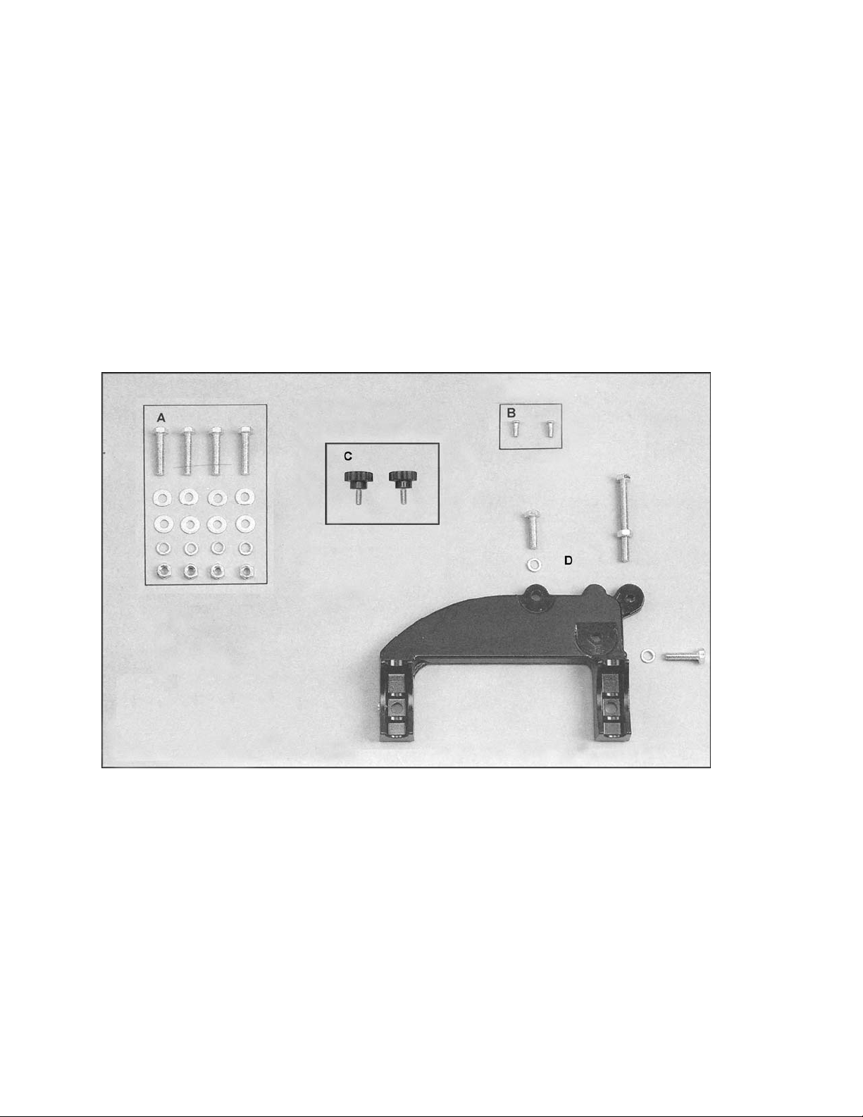
Fasteners
2 Table lock knobs
1 Table pin
1 Trunnion support br ac k et
1 Fastener package (see below)
1 Instruction Manual
1 Warranty Card
A. Saw Body to Stand
4 – M8x40 hex cap screws
(approx. 1-1/ 2" long)
8 – M8 flat washers
4 – M8 lock washers
4 – M8 hex nuts
B. Strain Relief Plate to Stand
2 – M5x12 pan head machine screws
C. Pulley Cover to Base
2 – Knobs
D. Trunnion Suppo rt Bracket to Saw Body
2 – M8x30 hex cap screws
(approx. 1-1/ 4" long)
2 – M8 lock washers
1 – M8x80 hex cap screw (for table stop -
approx. 3-1/8” long)
1 – M8 hex nut (for table stop)
7
Page 8
Assembly of JWBS-14CS
Tools Required for Assembl y
Metric combination wrench set and
adjustable wrench
#1 and #2 cross point screwdrivers
Exposed metal surfaces, such as the table, hav e
been given a protectiv e coating. This should be
cleaned with a soft cloth and solvent, such as
kerosene. Do not u se an abrasive pad, and do
not get solvents on plastic parts.
1. Remove pulley cov er from i nsi de of stand.
2. Place cabinet stand upright on a level
surface. If desired, the stand can be fur ther
stabilized by securing it to the floor with lag
screws through the inside corner holes. If
using a mobil e base, l ock the caster s bef or e
assembling or oper ating the band saw.
Saw body is heavy! Use
caution when lifting and st abilize until f irmly
attached to th e stand! Failu re to comply may
cause serious inj ury!
3. With t he aid of a second person, lif t the saw
body out of the shippi ng container and plac e
onto stand top. Be sure f ront of saw (with
JET logo) faces stand f r ont (J ET l ogo) .
4. Line up hole s in saw body wi th holes in t op
of stand. Fasten saw body to t he stand wit h
four M8 x 40 hex cap screws, eight M8
washers, four M8 lock washers, and f our M8
hex nuts (as shown in item A, page 8) .
Figure 10
Figure 11
Figure 12
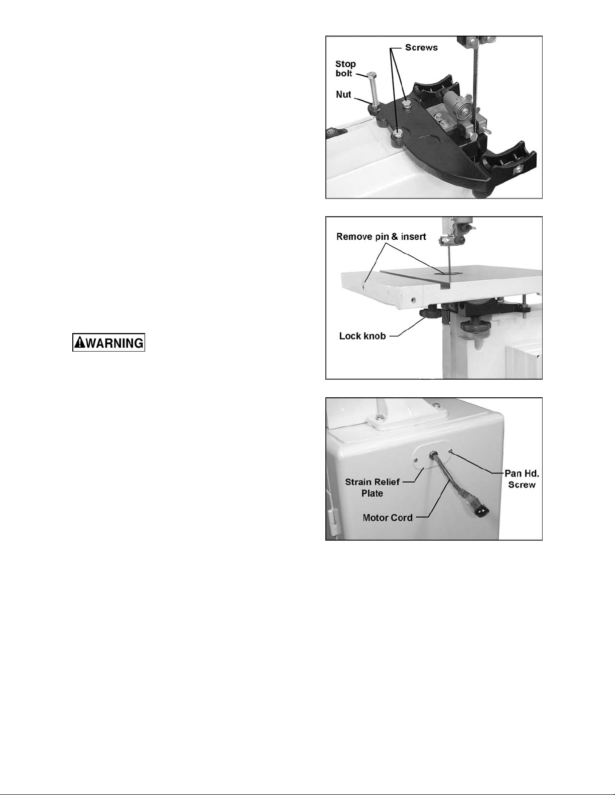
5. Push motor cord and strain relief plate
through the opening i n the side of the stand
(Fig. 12). Fasten t he strain relief plate to the
stand with two M 5 x 12 pan head machi ne
screws (shown in it em B, page 8).
6. Check the alignment of the pulleys by
placing a strai ght edge against the flat sides
of the mot or and wheel pulleys (Fi gure 13).
If the pulleys lie in a straight plane (Figure
14) they are aligned. If they do not lie in a
straight pl ane, loosen the set screw on one
of the pulleys and shift the pulley in or out
8
Page 9

until both pulleys lie in a straight plane.
Tighten set screw.
Figure 13
Figure 15
9. The v -belt i s properly tensi oned when fi nger
pressure between the two pulleys causes
approxim ately 1/2" deflection (Figure 16).
Figure 14
IMPORTANT: When m oving the pull eys, do
not position them beyond the end of the
shaft. Both pulleys must fully engage the
shaft and the key.
7. Open the lower door, and place the v-belt
around the motor pulley and the wheel
pulley (see Fi gur e 13).
8. Loosen the nuts o n the f our motor mounti ng
bolts (Figure 15) and tension the v-belt by
pushing down on the mot or. Tight en the four
motor mounting nuts.
Figure 16
10. Screw the two sm all knobs (Figure 17) int o
the threaded holes in the saw body. Slide
the pulley cover down over the knobs, and
tighten the knobs.
Figure 17
11. Att ach trunnion support br acket to saw body
with two M8 x 30 hex cap screws and two
9
Page 10

M8 lock washers, as shown in it em D, page
8. See Figure 18.
Figure 18
12. Thread nut onto table stop bolt (Figure 18)
and attach to trunnion support bracket as
shown.
13. To mount the table, remove pin and insert
from the tabl e (Figur e 19) .
Figure 20
17. Transportation and handling may have
caused some fasteners to loosen. Before
operating, c heck all screws, bolts, and nut s
to make sure they are snug. Operate
machine only af ter reading the entire manual
including blade tracking, blade guide
adjustments, and safety rules.
Grounding Instructions
Figure 19
14. Orient t he table so the saw blade will pass
through the slot in the table and into the
center opening. Continue holding up the
table, and rot ate the t able so the two screws
that are hanging vertically from below the
table will slide into the hol es on the trunni on
support bracket. Lower the table. The
screws should now protrude below the
trunnion support br acket - attach l ock knobs
to the ends of these screws. (Figure 19).
15. Re- install table insert and table pin.
16. Connect the plugs of the motor cord and
switch cord (Figure 20).
This band saw must be
grounde d while in use to prot e c t t he ope r a tor
from electri c sho ck.
In the event of a malfunction or breakdown,
grounding prov i des a path of least resistanc e f or
electric current to reduce the risk of electric
shock. This tool is equipped with an electric cord
having an equipment-groundi ng c onduc tor and a
grounding plug t hat looks similiar to the plug i n
Figure 21. The plug must be inserted into a
matching outlet that is properly installed and
grounded in accord ance wit h all l ocal codes and
ordinances.
Figure 21
Do not modify the plug provided. If it will not fi t
the outlet , have the proper outlet i nstalled by a
qualified elec trician.
Improper connection of the equipmentgrounding conductor can result in a risk of
electric shock. The conductor, with insulation
10
Page 11

having an outer surface that is green with or
without yellow stripes, is the equipmentgrounding conduct or. If repai r or replac ement of
the electric cord or plug is necessary, do not
connect the equipment-grounding conductor t o a
live terminal.
Check with a qualified electrician or service
personnel if the grounding instructions are not
completely understood, or if in doubt as to
whether the tool is properly grounded.
Repair or replace a damaged or worn cord
immediately.
115 Volt Operation
As received f rom the factory, your band saw i s
ready to run at 115 volt operation. This band
saw, when wired for 115 volts, is intended for
use on a circuit t hat has an outlet and a plug that
looks like the one illustrated in Figure 21. A
temporary adapt er, lik e the adapt er in Fi gure 22,
may be used to connect this plug to a two-pole
receptacl e, as shown in Figure 22, if a properly
grounded outl et is not av ailable. The temporar y
adapter should only be used until a properly
grounded outlet can be installed by a qualified
electrician. This adapter is not applicable in
Canada. The green colored rigid ear , lug, or t ab,
extending fr om the adapter, must be connect ed
to a permanent ground such as a properly
grounded outlet box, as shown in Figure 22.
electrician for proper procedures to install
the plug. The band saw must comply with all
local and national codes after the 230 volt
plug is installed.
4. The band saw with a 230 volt plug should
only be connected to an outlet having the
same confi guration (Fi gure 24). No adapt er
is availabl e or should be used with the 230
volt plug.
Important: In all cases (115 or 230 volts),
make certain the receptacle in question is
properl y grounded. If you are not sure, have
a registered electrician check the receptacl e.
Figure 22
230 Volt Conversion
If 230V, single-phase operation is desired, the
following inst r uc tions must be followed:
1. Disconnect machine from power source.
2. This band saw is supplied with four motor
leads that are connec ted for 115V operation,
as shown in Figure 23. Reconnect these
four motor leads for 230V operation, as
shown in Figure 23.
3. The 115V att achment plug suppl ied with t he
band saw must be r eplaced with a UL/CS A
listed plug suitable for 230V operation, as
shown in Figure 24. Contact your local
authorized JET service center or qualified
Figure 23
Figure 24
Extens ion Cords
Use only three wire extension cords that have
three-prong grounding plugs and three-pole
receptacles t hat accept the tool’s plug.
11
Page 12

Make sure the cord is in good condition, and
A
e
heavy enough to carry the current your band
saw will draw. An undersized cord will cause a
drop in line voltage, resulting in loss of power
and overheating. Figure 25 shows the correct
size to use depending on cord length and the
ampere rating on your machine’s nameplate. If
in doubt, use the next heavier gauge. The
smaller the gauge number, the heavier the cord.
Repair or replace a damaged or worn cord
immediately.
Minimum Gauge Extension Cord
mp
rating
0-6 120
6-10 120
10-12 120
12-16 120
Line
voltage
Total length of
cord in feet
0 to 25 18
25 to 50 16
50 to 100 16
over 100 14
0 to 25 18
25 to 50 16
50 to 100 14
over 100 12
0 to 25 16
25 to 50 16
50 to 100 14
over 100 12
0 to 25 14
25 to 50 12
over 50
Cord gaug
not recommended
(AWG)
Figure 25
Figure 26
Adjusting 90° Table Stop
1. Disconnect machine from power source.
2. Loosen lock knobs (Figure 26) and tilt
table left until it rests agai nst the table stop.
3. Use a square placed on the table and
against the bl ade (Figure 27) to see if the
table is 90 degrees to the blade.
Adjustments
Un plug the machi ne from the
power source before making any repairs or
adjustments. Failure to comply may cause
serious injury.
Tilting the Table
1. Loosen two lock knobs (Figure 26).
2. Tilt table up to 45 degrees to the right or
up to 10 degrees to the left. The angle can
be read on the scale mounted to the
trunnion.
3. Tighten two lock knobs (Figure 26).
Note: Tabl e stop must be rem ov ed to til t tabl e to
the left.
Figure 27
4. If an adjustment is necessary, loosen loc k
knobs, tilt table to the right, and lock in
place.
5. Loosen jam nut and t urn t able stop ( Figure
26) left or right to raise or lo wer the stop.
Tighten jam nut to hold table stop in place.
6. Unlock tabl e, tilt back onto table rest and
confirm table is 90 degrees with the blade.
7. If necessary, adj ust scale pointer to zero.
12
Page 13

Changing Blades
Blade teeth are sharp! Use
care when handling the saw blade. F ailure to
comply may cause seriou s injury.
1. Disconnect machine from power source.
2. Loosen blade tension by turning the
tension knob counter c lockwise (Figure 28).
Figure 28
3. Remove the table insert and the table pin.
4. Open both wheel covers.
5. Remove the blade from between upper
and lower blade guides. Remove blade
from upper and lower wheels. Turn blade
to direct through slot in table.
6. G uide new blade through table slot. Pl ace
blade in upper and lower blade guides.
Note: The blade teeth should face the
operator, and they should point down
toward the table.
7. Place blade in t he mi ddl e of t he upper a nd
lo wer wheel.
8. Re-install table insert and table pin.
9. Tension and track blade before operating
saw. Find instructions for tensioning and
tracking the blade under "Adjusting Blade
Tension" and "Adjusting Blade Tracking" .
upper wheel slide bracket indicates the
approximate tension according to the width
of the blade. Init ially, set the blade t ension to
correspond to the bl ade width as marked on
the gauge.
3. As you becom e more experienced with the
saw, you may find it necessary to change
the blade tension from the initial setting.
Changes in blade width and the type of
material being cut will have an effect on
blade tension.
4. Keep in mind that too little or too much
blade tension can c ause bl ade br eak age.
Adjusting Blade Tracking
Disconn ect mach ine fro m the
power source. Never adjust blade tracking
with the machi ne running. Failure to comply
may cause serious injury.
“Tracking” refers to how the blade is situated
upon the wheels while in motion. The blade
should track in t he c enter of bot h wheels.
1. The blade must be properly tensioned
before adjusting blade tracking. Make sure
blade guides and blade bearings do not
interfere with the blade.
2. Open the top wheel cov er. Rotat e the wheel
forward by hand, and observe the position of
the blade on the wheel - it should be in the
center of the wheel.
3. If adjustment is necessary, l oosen wing nut
(Figure 29), and tighten tracking knob
slightly to move blade toward rear of
machine. Slightly loosening the tracking
knob will cause t he blade to track toward the
front of the machi ne.
4. After blade is tracking in the center of the
wheel, tighten the wing nut.
Adjusting Blade Tension
1. Disconnect machine from power source.
2. Turn blade tension knob (Figure 28)
clockwise to t ension blade. A gauge on t he
13
Page 14

Figure 29
Adjusting Upper Blade Guide Assembly
1. Disconnect machine from power source.
2. Loosen lock knob (A, Figure 30) and raise
or lower upper blade guide assembly (B,
Figure 30) to just above the material being
cut.
Adjusting Blade Guide and Blade Support Bearing
Blade guard has been
removed for picture clarity. Never operate
the band saw without all gu ards in place and
in workin g or de r .
1. Disconnect machine from power source.
2. Blade must already be tensioned and
tracki ng properly.
3. Loosen thumb screws (E, Figure 31) and
move guide blocks (C, Figure 31) as close to
the blade as possibl e without pinching it.
Figure 30
3. Ti ghten lock knob. Make sure blade guide
blocks (C, Figure 30) are still flat to the
blade. If adjustment is necessary, loosen
lock knob (A, Figure 30) and rotate
assembly until guide blocks are flat to blade.
4. If movement of the blade guide assembly
seems “stiff ” when being raised or l owered,
it can be adj usted to slide m ore easily. This
is controlled by an internal spring and ball
which provi de varyi ng degrees of resistance
against the guide post. Use the set screw
(D, Figure 30) to adjust the tension of this
spring. To adjust tension on the spring,
loosen knob (A, Figure 30), use a hex
wrench to tighten or loosen set screw (D,
Figure 30) until desired tension is reached,
then re-tight en k nob ( A, Figure 30).
Figure 31
4. Tighten thumb screws (E, Figure 31).
5. Loosen thumb screw (F, Figure 31) and tur n
knurled knob (G, Figure 31) to move the
guide block bracket in or out until the front
edge of the gui de blocks are just behi nd the
"gullets" of the saw teeth.
6. Tighten thumb screw (F, Figure 31).
7. The blade support bearing (K, Figure 31)
should be adjusted so that the back edge of
the blade ov erlaps the front face of the ball
bearing approximately 1/8". To change
position of the bearing, remove screw (L,
Figure 31), and bearing (K, Figure 31).
Loosen thumb screw (H, Figure 31) and
back off knurled knob (J, Figure 31)
completely to rem ov e the bearing shaft.
8. Notice the bearing holder on the shaft is
eccentri c. Index the bearing shaft t o another
position and slide it back in, maki ng sure the
flange on the thumb screw (H, Figure 31)
properly seats int o the gr oov e of t he beari ng
14
Page 15

shaft. Re-i nstall the bearing and the screw.
Examine the overlap between the bearing
face and the blade. Change the position of
the bearing shaft until the overlap is
approxim ately 1/8".
9. With the thumb screw (H, Figure 31) still
loosened, adjust the distance from bearing
to blade. T urn knurl ed knob (J, Figur e 31) t o
move the support bearing (K, F igure 31) in
or out until the bearing is 1/64" behind the
blade. (NOTE: To set this distance quickly,
you can place a dol lar bill or piece of paper
between support bearing and back of blade.)
10. Tighten thumb screw (H, Figure 31).
11. Repeat procedures 1 through 10 for the
Lower Blade Guide Assem bly .
15
Page 16

Troubleshooting JWBS-14CS Band Saw
Trouble Probable Cause Remedy
Saw unplugged. Check all plug connections.
Saw stops or will not
start.
Fuse blown, or cir c uit break er tr ipped. Replace f use, or r eset ci r c uit breaker.
Cord damaged. Replace cord.
Does not make
accurate 45 or 90
degree cuts.
Blade wanders during
cut.
Saw makes
unsatisfactory cuts.
Table stop not adjusted c or r ec tly.
Angle pointer not set accurately.
Miter gauge out of adj ustm ent. Adjust miter gauge.
Fence not ali gned with blade.
Warped wood. Select another piece of wood.
Excessive f eed r ate. Reduce feed rate.
Incorrect blade for cut. Change blade to corr ec t t y pe.
Blade tension not set properly.
Guides not set properly. Adjust guides.
Dull blade. Replace blade.
Blade mounted wrong.
Gum or pitch on blade.
Check blade with square and adjust
table stop.
Check blade with square and adjust
pointer.
Check and adjust fenc e ( see fenc e
manual).
Set blade tension acc or ding to blade
size.
Teeth should fac e oper ator and point
downward.
Remove blade and clean wit h ov en
cleaner or ot her solvent.
Blade does not come
up to speed.
Saw vibrates
excessively.
Incorrect blade for cut. Change blade to corr ec t t y pe.
Gum or pitch on table. Clean table.
Extension cord too light or too long.
Low shop voltage. Contact your loc al elec tric company.
Base on uneven floor. Reposition on fl at, lev el surface.
Bad v-belt. Replace v-belt.
Motor mounting is loose. Tighten motor mount fasteners.
Loose fasteners. Tighten fasteners.
Replace with adequat e si z e and
length cord.
16
Page 17

Optional Accessories
708718R JRF - 14 Deluxe Rip Fence Assembly with Resaw
Includes guide bars, rip fence assembly, resaw post, fasteners, and mounting instructions with
parts list.
708717 JRB-14 Ri ser Block Kit
Increase s depth of cut from 6" maximum to 12" maxim um. Includes 6" c ast block, long frame
bolt, front and back blade guar ds, 105” blade, and mounting instruc tions with parts li st.
708716 JMG-14 Mi t er Gauge Assembly
For str aight and angle cutting. Includes guide bar, pivoting support body , and adjustable
stops.
708719 JBB-14 Bl ade Block Set
Includes upper and lower replacement bloc ks made from a non-metallic composi te material
with a dry lubr ic ant to reduce fricti on and heat.
708127 JRBG- 14 Roller Bearing Guides
Dual bearing system maximizes contac t and minimizes friction against the blade. Includes
upper and lower guide assem blies, mounting studs, adaptor blocks, and mounting hardware.
Replacement Parts
Replacement par ts are li sted on the f ollowing page s. To order parts or reac h our servi ce depar tm ent, call
1-800-274-6848, Mon day t hrough Fr iday (see our web sit e f or busi ness hours, www.j ett ool s.com). Havi ng
the Model Num ber and S eri al Num ber of y our machi ne avail abl e when you cal l will allow us to serve you
quickly and acc ur ately.
17
Page 18

Parts List – Body Assembly (JWBS-14CS Band Saw)
Index No. Part No. Description Size Qty
1 ............... 150100AW ...............Upper Arm Fram e .................................................................................. 1
2 ............... 150037W .................Table ..................................................................................................... 1
3 ............... 100038 ....................Table Pin ............................................................................................... 1
4 ............... 708719 ....................Guide Block ........................................................................................... 4
5 ............... 150005A ..................Upper Support Bracket Post .................................................................. 1
6 ............... 150006A ..................Support Bracket ..................................................................................... 2
7 ............... 150007A ..................Guide Post ............................................................................................ 1
8 ............... TS-1490021 .............Hex Cap Scre w ..................................................M8x16 ........................ 2
9 ............... WF083030 ...............Flat Washer ........................................................M8 .............................. 1
10 ............. 150010A ..................Nut ........................................................................................................ 4
11 ............. 990708 ....................Screw .................................................................M8x40 ........................ 2
12 ............. TS-1482031 .............Hex Cap Sc re w ..................................................M6x16 ........................ 1
13 ............. 150013A ..................Thu mb Screw .....................................................M6x16 ........................ 3
14 ............. 150014A ..................Thu mb Screw ....................................................M6x12 ........................ 5
15 ............. 150015A ..................Upper Spacing Sleeve ........................................................................... 2
16 ............. BB-6200ZZ ..............Ball Bearing ........................................................................................... 2
17 ............. 990908 ....................Pan Head Screw* ...............................................M6x8 .......................... 2
18 ............. 100002A ..................Upper Wheel Blade Guard ..................................................................... 1
19 ............. TS-148201 ...............Hex Cap Screw ..................................................M 6 X10........................ 2
20 ............. TS-1550041 .............Washer...............................................................M6 .............................. 4
21 ............. 990651 ....................Lock Knob ..........................................................M10x30 ...................... 1
22 ............. 199037 ....................Table Insert ........................................................................................... 1
23 ............. 992311 ....................Spring Pin.............................................................................................. 1
25 ............. TS-1482041 .............Phillips Pan Head Machine Screw ......................M6x20 ........................ 2
26 ............. 150024
27 ............. TS-1551061 .............Loc k Washer* .....................................................M8 .........................2(2)*
28 ............. 150028W .................Inner Wheel Cover ................................................................................. 1
29 ............. 155029W .................Outer Wheel Cover ................................................................................ 1
30 ............. 100031 ....................Pin......................................................................................................... 4
31 ............. 990180 ....................Hex Head Bolt ....................................................M16x55 ...................... 1
32 ............. WF-164030 ..............Washer...............................................................M16 ............................ 2
33 ............. TS-1540101 .............Hex Nut ..............................................................M16 ............................ 1
34 ............. 100188 ....................Base ...................................................................................................... 1
35 ............. 110045 ....................Trunnion Support Bracket ...................................................................... 1
36 ............. 100042 ....................Trunnion ................................................................................................ 2
37 ............. 100051 ....................Scale ..................................................................................................... 1
38 ............. 100041 ....................Trunnion Clamp Shoe ............................................................................ 2
39 ............. TS-1491081 .............Hex Cap Sc re w ..................................................M10 x50 ...................... 2
40 ............. TS-1482021 .............Hex Cap Sc re w ..................................................M6x12 ........................ 6
41 ............. 110049 ....................Pointer................................................................................................... 1
42 ............. 990821 ....................Pan Head Screw ................................................M5x6 .......................... 5
43 ............. TS-1490151 .............Hex Cap Screw* .................................................M8 x80 ........................ 1
44 ............. TS-1540061 .............Hex Nut* .............................................................M8 .............................. 1
45 ............. TS-1490051 .............Hex Cap Screw* .................................................M8X30........................ 2
46 ............. 990554 ....................Lock Knob .......................................................... .................................. 2
47 ............. TS-152303 ...............Set Screw ...........................................................M6x10 ........................ 1
48 ............. 100063 ....................Belt Pulley ............................................................................................. 1
49 ............. 992547 ....................Retaining Ring ....................................................................................... 1
50 ............. 110065 ....................Lower Whee l Sh aft ................................................................................ 1
51 ............. 992009 ....................Key.....................................................................5x5 x20 ....................... 2
52 ............. BB-
53 ............. 990293 ....................Hex Head Bolt (Left Thread) ...............................M8x25 ........................ 1
54 ............. 150054 ....................Hex Head Bolt ....................................................................................... 2
55 ............. 150055 ....................Lower Support Bracket Post .................................................................. 1
56 ............. 150056 ....................Switch Backing Plate ............................................................................. 1
57 ............. 523028 ....................Switch Box ............................................................................................ 1
58 ............. 994542 ....................Switch ................................................................................................... 1
....................Catch Knob ........................................................................................... 2
6204RS ..............Ball Bearing ........................................................6204RS ...................... 2
18
Page 19

Index No. Part No. Description Size Qty
59 ............. 995001 ....................Power Cord (Switch To Motor) ............................................................... 1
60 ............. 995002 ....................Power Cord (Switch To Power Source) .................................................. 1
61 ............. 990814 ....................Self Tapping Screw ............................................M 3.5x19 ..................... 2
62 ............. TS-1550021 .............Flat Wash er ........................................................M4 .............................. 2
63 ............. TS-1533042 .............Phillips Pan Head Machine Screw ......................M5x12 ........................ 6
64 ............. 523024 ....................Wire Clip ............................................................................................... 1
65 ............. TS-1533032 .............Phillips Pan Head Machine Screw ......................M5x10 ........................ 4
66 ............. 150066 ....................Stud ...................................................................................................... 2
67 ............. 150902 ....................Lower Hinge .......................................................................................... 1
68 ............. WF051210 ...............Washer...............................................................M5 .............................. 2
69 ............. 150069N ..................Lower Whee l Gua r d ............................................................................... 1
70 ............. 198672 ....................Lower Whee l ......................................................................................... 1
71 ............. 100025A .................Wheel Protecto r ..................................................................................... 2
72 ............. 198242 ....................Upper Wheel ......................................................................................... 1
73 ............. 992522 ....................Retaining Ring ....................................................R35 ............................ 2
74 ............. BB-6202ZZ ..............Ball Bearing ........................................................6202ZZ....................... 2
75 ............. TS-1540083 .............Hex Nut ..............................................................M12 ............................ 1
76 ............. ................................Saw Blade (Local Purchase) .................................................................. 1
77 ............. 990804 ....................Self Tapping Screw ............................................M 4x8 ........................ 16
78 ............. 150901 ....................Upper Hinge .......................................................................................... 1
79 ............. 150079 ....................Catch .................................................................................................... 2
80 ............. 150080 ....................Clip........................................................................................................ 2
81 ............. 150081 ....................Bracket .................................................................................................. 2
82 ............. 110070 ....................Blade Guard .......................................................................................... 1
83 .............
................. 100016ACP-1 ..........Sliding Bracket Assy (includes items 84 thru 93, and 104)...................... 1
84 ............. 100016A-1 ...............Slidin g Br a ck e t ...................................................................................... 1
85 ............. 100019 ....................Shaft Hinge ........................................................................................... 1
86 ............. 150086 ....................Upper Wheel Shaft ................................................................................ 1
87 ............. 100021 ....................Steel Pin ................................................................................................ 2
88 ............. 992314 ....................Spring Pin.............................................................................................. 1
89 ............. 100015A ..................Coil Spring............................................................................................. 1
90 ............. 150090 ....................Square Nut ............................................................................................ 1
91 ............. 990652 ....................Lock Knob ............................................................................................. 1
92 ............. NW080000 ...............Wing Nut ............................................................M8 .............................. 1
93 ............. 990653 ....................Blade Adjusting Screw ........................................................................... 1
95 ............. TS-1490071 .............Hex Cap Screw* .................................................M8 x40 ........................ 4
96 ............. TS-1550061 .............Flat Wash er* ......................................................M8 .............................. 4
97 ............. 150097 ....................Washer.................................................................................................. 2
98 ............. 994181 ....................Steel Bal l ............................................................................................... 1
99 ............. 150099 ....................Spring.................................................................................................... 1
100 ........... TS-1525011 .............Socket Set Screw ...............................................M10x10 ...................... 1
101 ........... 150101 ....................Lower Wheel Blade Guard ..................................................................... 1
102 ........... WE050000 ...............Gear Washer ......................................................M5 .............................. 2
103 ........... 998654 ....................Strain Relief ........................................................................................... 2
104 ........... 100018 ....................Indicator ................................................................................................ 1
105 ........... WI080000 ................Gear Was h e r ......................................................M8 .............................. 2
................. JWBS14-HK.............Hardware Kit (not shown) ...................................................................... 1
* ............... in cluded in hardware kit
990811 ....................Self Tapping Screw ............................................M3 .5x12 ..................... 2
19
Page 20

Exploded View – Body Assembly (JWBS-14CS Band Saw)
20
Page 21

Parts List – Closed Stand Assembly (JWBS-14CS Band Saw)
Index No. Part No. Description Size Qty
1 ............... 150501W .................Stand .................................................................................................... 1
2 ............... 150502W .................Doo r ...................................................................................................... 1
3 ............... 150503 ....................Door Latch Assembly............................................................................. 1
4 ............... WBS14CS -04 ..........Wash er.................................................................................................. 2
5 ............... WBS14CS -05 ..........Pan Head Screw ................................................M4x5 .......................... 2
6 ............... PG-M02 ...................JET Plaque ............................................................................................ 1
7 ............... TS-1533031 .............Flat Head Screw .................................................M5x10 ........................ 2
8 ............... 150508W .................Plate ...................................................................................................... 1
9 ............... 998621 ....................Strain Relief ........................................................................................... 1
10 ............. TS-1533042 .............Phillips Pan Head Machine Screw* .....................M5x12 ........................ 2
11 ............. 150511W .................Motor Plate ............................................................................................ 1
12 ............. 150512W .................Motor ..................................................................1HP, 1Ph, 115/230V ... 1
13 ............. 600013 ....................Motor Pulley .......................................................................................... 1
14 ............. VB-A50 ....................V-BELT ................................................................................................. 1
15 ............. TS-1523011 .............Socket Set Screw ...............................................M6x6 .......................... 1
16 ............. 100254 ....................Pulley Box ............................................................................................. 1
17 ............. 990624 ....................Knob* .................................................................................................... 2
20 ............. TS-1490041 .............Hex Cap Sc re w ..................................................M8x25 ........................ 4
21 ............. 991516 ....................Square Neck Bolt................................................M8x16 ........................ 4
22 ............. TS-1550051 .............Flat Wash er* ......................................................M8 ....................... 16(4)*
23 ............. TS-155108 ...............Lock Washer * .....................................................M8 ....................... 12(4)*
24 ............. TS-1540061 .............Hex Nut* .............................................................M8 ....................... 12(4)*
26 ............. 995003A ..................Motor Cord ............................................................................................ 1
27 ............. 150527 ....................Pad ....................................................................................................... 2
................. WBS14CS-HK .........Hardware Kit (Not Shown) ..................................................................... 1
* ............... in cluded in hardware kit
21
Page 22

Exploded View – Closed Stand Assembly (JWBS14-CS Band Saw)
22
Page 23

Electrical Connections – 115 volt (JWBS-14CS Band Saw)
23
Page 24

Electrical Connections – 230 volt (JWBS-14CS Band Saw)
24
 Loading...