

Page 1
This .pdf document is bookmarked
Operating Instructions and Parts Manual
10-inch Jointer-Plane r
Model JJP-10BTOS
JET
427 New Sanford Road
LaVergne, Tennessee 37086 Part No. M-707410
Ph.: 800-274-6848 Revision B 08/2014
www.jettools.com Copyright © 2014 JET
Page 2

1.0 Warranty and Service
JET warrants every product it sells against manufacturers’ defects. If one of our tools needs service or repair, please
contact Technical Service by calling 1-800-274-6846, 8AM to 5PM CST, Monday through Friday.
Warranty Period
The general warranty lasts for the time period specified in the literature included with your product or on the official JET
branded website.
• JET products carry a limited warranty which varies in duration based upon the product. (See chart below)
• Accessories carry a limited warranty of one year from the date of receipt.
• Consumable items are defined as expendable parts or accessories expected to become inoperable within a
reasonable amount of use and are covered by a 90 day limited warranty against manufacturer’s defects.
Who is Covered
This warranty covers only the initial purchaser of the product from the date of delivery.
What is Co vered
This warranty covers any defects in workmanship or materials subject to the limitations stated below. This warranty does
not cover failures due directly or indirectly to misuse, abuse, negligence or accidents, normal wear-and-tear, improper
repair, alterations or lack of maintenance. JET woodworking machinery is designed to be used with Wood. Use of these
machines in the processing of metal, plastics, or other materials may void the warranty. The exceptions are acrylics and
other natura l item s t hat ar e made specifically f or wood turni ng.
Warranty Limitations
Woodworking products with a Five Year Warranty that are used for commercial or industrial purposes default to a Two
Year Warranty. Please contact Technical Service at 1-800-274-6846 for further clarification.
How to Get Technical Support
Please contact Technical Service by calling 1-800-274-6846. Please note that you will be asked to provi d e pr o of of
initial p u rchase when calling. If a product requires furth er inspection, the Technic al Service representati v e will expl ain
and assist with any additional action needed. JET has Authorized Service Centers located throughout the United States.
For the name of an Authorized Service Center in your area call 1-800-274-6846 or use the Service Center Locator on the
JET website.
More Information
JET is constantly adding new products. For complete, up-to-date product information, check with your local distributor or
visit the JET website.
How S tate Law Applies
This warranty gives you specific legal rights, subject to applicable state law.
Limitations on This Warranty
JET LIMITS ALL IMPLIED WARRANTIES TO THE PERIOD OF THE LIMITED WARRANTY FOR EACH PRODUCT.
EXCEPT AS STATED HEREIN, ANY IMPLIED WARRANTI ES OF MERCHANTABILITY AND FITNESS FOR A
PARTICULAR PURPOSE ARE EXCLUDED. SOME STATES DO NOT ALLOW LIMITATIONS ON HOW LONG AN
IMPLIED WARRANTY LASTS, SO THE ABOVE LIMITATION MAY NOT APPLY TO YOU.
JET SHALL IN NO EVENT BE LIABLE FOR DEATH, INJURIES TO PERSONS OR PROPERTY, OR FOR INCIDENTAL,
CONTINGENT, SPECIAL, OR CONSEQUENTIAL DAMAGES ARISING FROM THE USE OF OUR PRODUCTS. SOME
STATES DO NOT ALLOW THE EXCLUSION OR LIMITATION OF INCIDENTAL OR CONSEQUENTIAL DAMAGES, SO
THE ABOVE LIMITATION OR EXCLUSION MAY NOT APPLY TO YOU.
JET sells through distributors only. The specifications listed in JET printed materials and on official JET website are given
as general information and are not binding. JET reserves the right to effect at any time, without prior notice, those
alterations to parts, fittings, and accessory equipment which they may deem necessary for any reason whatsoever. JET
branded products are not sold in Canada by JPW Industries, Inc.
Product Listing with Warranty Period
90 Days – Parts; Consumable items; Light-Duty Air Tools
1 Year – Motors; Machine Accessories; Heavy-Duty Air Tools; Pro-Duty Air Tools
2 Year – Metalworking Machinery; Electric Hoists, Electric Hoist Accessories; Woodworking Machinery used
for industrial or commercial purposes
5 Year – Woodworking Machinery
Limited Lifetime – JET Parallel clamps; VOLT Series Electric Hoists; Manual Hoists; Manual Hoist
Accessories; Shop Tools; Warehouse & Dock products; Hand Tools
NOTE: JET is a division of JPW Industries, Inc. References in this document to JET also apply to JPW Industries, Inc., or
any of its successors in interest to the JET brand.
®
2
Page 3

2.0 Table of Contents
Section Page
1.0 Warranty and Service .............................................................................................................................. 2
2.0 Table of Contents .................................................................................................................................... 3
3.0 Safety warnings ...................................................................................................................................... 4
3.0 Features ................................................................................................................................................. 7
4.0 Specifications .......................................................................................................................................... 7
5.0 Optional acc essories ............................................................................................................................... 7
6.0 Shipping Contents ................................................................................................................................... 8
7.0 Unpacking ............................................................................................................................................... 8
8.0 Assembly .............................................................................................................................................. 10
9.0 Jointer setup ......................................................................................................................................... 12
10.0 Planer setup ........................................................................................................................................ 12
11.0 Operating controls ............................................................................................................................... 13
12.0 Adjustments ........................................................................................................................................ 15
13.0 Basic Operations ................................................................................................................................. 18
14.0 Maintenance ....................................................................................................................................... 22
15.0 Lubrication .......................................................................................................................................... 22
16.0 Troubleshooti ng the JJP-10BT ............................................................................................................ 23
17.0 Parts ................................................................................................................................................... 26
18.0 Electric al Connec tion .......................................................................................................................... 39
The specificati ons in t his manual are giv en as general inf ormation and are not bindi ng. JET reserv es the right
to effect, at any time and without prior notice, changes or alterations to parts, fittings, and accessory
equipment deemed nec essary for any reason whatsoev er.
3
Page 4

3.0 Safety warnings
1. Read and understand the ent ire owner's manual befor e att em pting assembly or operation.
2. Read and understand the warnings po sted on the m achine and i n thi s manual. Fail ure to comply wit h
all of these warnings m ay cause seriou s i njury.
3. Replace the warning labels if they become obscured or removed.
4. This Woodworking Jointer-planer is designed and intended for use by properly trained and
experienced personnel only. If you are not familiar with the proper and safe operation of a
woodworking j ointer or planer, do not use until proper trai ning and knowledge have been obtained.
5. Do not use this for ot her than its int ended use. If used for ot her purposes, JET di sclaim s any real or
implied warrant y and holds itself harmless from any injury t hat may result from that use.
6. Always wear approved safety glasses/face shields while using this woodworking jointer-planer.
Everyday eyeglasses only have impact resistant lenses; they are not safety glasses.
7. Before operati ng this woodworking joi nter-planer, remove ti e, rings, watches and other jewelr y, and
roll sleev es up past the elbows. Remove all l oose clot hing and confine long hai r. Non- slip foot wear or
anti-ski d floor strips are recommended. Do not wear gloves.
8. Wear ear protector s (plugs or muffs) during extended peri ods of oper ation.
9. Some dust created by power sanding, sawing, grinding, drilling and other construction activities
contain chemi cals known to cause cancer , bir th defects or other r eproductiv e harm . Some exampl es
of these chemic als are:
• Lead from lead based paint.
• Crystalli ne sil ic a from bricks, cement and other masonry pr oduc ts.
• Arsenic and chromium from chemically treated lumber.
Your risk of exposure varies, depending on how often you do this type of work. To reduce your
exposure to these chemicals, work in a well-ventilated area and work with approved safety
equipment, such as face or dust masks that are specifically designed to filter out microscopic
particles.
10. Do not oper ate this machine while tired or under the influence of drugs, alcohol or any m edic ation.
11. Mak e c er tain the switch is in the OFF position before connecting the machine to the power source.
12. Mak e c er tain the machine is properly grounded.
13. Mak e all machine adjustment s or maintenanc e with the machine unplugged from the power source.
14. Remove adjusting keys and wrenches. Form a habit of checking to see that keys and adjusting
wrenches are removed from the machine before turning i t on.
15. Keep safety guards in place at all times when the machine is in use. If removed for maintenance
purposes, use extreme caution and replace the guards immediately.
16. Mak e sure t he woodworking jointer - planer is firmly secured to the fl oor or benc h before use.
17. Check damaged parts. Before further use of the machine, a guard or other part that is damaged
should be carefully checked to determine that it will operate properly and perform its intended
function. Chec k for alignment of moving par ts, binding of moving parts, breakage of parts, mounting
and any other condi ti ons that m ay affect its operati on. A guard or ot her part that i s damaged should
be properly repaired or replaced.
18. Pr ov ide for adequate space surrounding work ar ea and non-glare, overhead lighting.
19. Keep the floor around the machine cl ean and free of scrap material, oil and grease.
4
Page 5
20. Keep v isitors a safe distance from the work area. Keep children away.
21. Mak e y our workshop child proof with padloc k s, m aster switches or by removing starter key s.
22. Giv e your work undivi ded attention. Looki ng around, carryi ng on a conversati on and “horse-play” ar e
careless acts that can r esul t in serious injury.
23. Maint ain a bal anced stance at al l tim es so that you d o not f all or l ean against t he cut terhead or other
moving part s. Do not over r eac h or use excessive force to perform any machine oper ation.
24. Use the right tool at the corr ect speed and f eed rat e. Do not force a t ool or att achment to do a job for
which it was not designed. T he ri ght tool will do the job better and safer.
25. Use recommended accessories; improper accessories may be hazardous.
26. Mai ntain tools with care. K eep knives sharp and clea n for the best and saf est performance. Foll ow
instructions for lubricating and changing accessories.
27. T ur n off the machi ne before cleaning. Use a brush or compressed air to r emove chips or debris — do
not use your hands.
28. Do not stand on the machine. Serious injury c oul d oc c ur if the mac hine tips over.
29. Never leave the machine running unattended. Turn t he power off and do not leave the machine until it
comes to a complete stop.
30. Bef ore turning on machi ne, remove all ext ra equipment such a s keys, wrenches, scrap, stock, and
cleaning rags away from the machine.
31. A lways use a hol d-down or push bl ock when surf acing stock less than 12" i nches long, or 3 i nches
wide, or 3 inches thic k.
32. Do not perf orm jointing operat ions on material shorter than 8", narrower than 3/4" or l ess than 1/4"
thick.
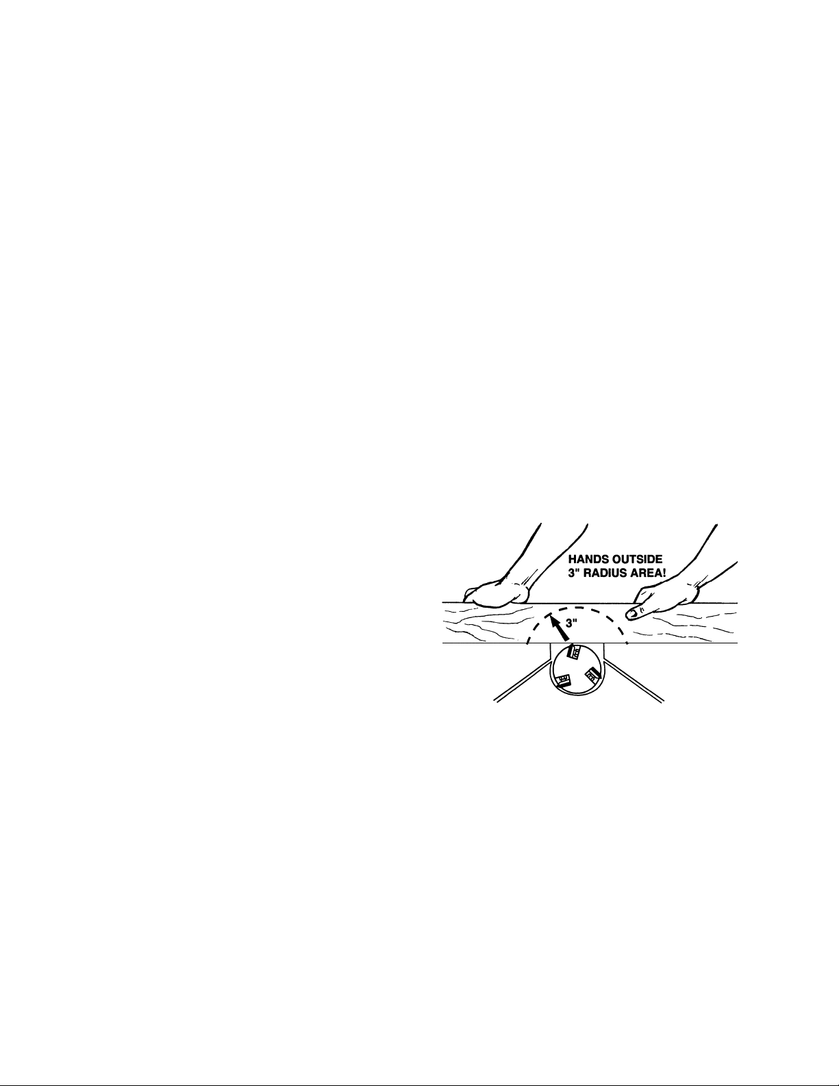
33. T he hands must never be cl oser t han 3 inches to
the cutter head ( see Figur e) .
34. Never apply pressure to stock directly over the
cutterhead. This m ay result in the stock ti pping
into the cutterhead along with the operator's
fingers. Posi tion hands away from extr em e ends
of stock, and push through with a smooth, ev en
motion. Nev er back workpiece toward the infeed
table.
35. To avoid kickback, the grain must run in the
same direction you are cutting. Before
attempting to joint or plane, each work piece m ust be carefully examined for stock conditi on and gr ain
orientation.
36. W hen working wit h a s wirl grai n wood or burl s, m aki ng it necessary t o plane agai nst t he gr ain, use a
lesser depth of c ut and a slow rate of f eed.
37. Move the hands in an alternate motion from back to front as the work continues through the cut. Never
pass the hands directly over the cutter knife. As one hand approaches the knives remove it from the
stock in an arc motion and place it back on the stock in a position be yond the cu tte r knife ( Fig. 18).
38. At all times hold the stock firmly.
- - SAVE THESE INSTRUCTIONS - -
5
Page 6

Familiariz e y our self with the following safety noti c es used in this manual:
This means that if precautions are not heeded, it may result in minor injury and/or
possible machine damage.
This means that if precauti ons are not heeded, it may result in serious injury or possibly
even death.
Read and understand the entire contents of this manual before attempting
assembly or operat io n! Failure to comply may cause serious injury!
6
Page 7
3.0 Features
Features
4.0 Specifications
Model number .................................................................................................................................... JJP-10BTOS
Stock number .............................................................................................................................................. 707410
Cutterhead speed ................................................................................................................................... 9000 RPM
Cuts per minute ............................................................................................................................................ 18,000
Number of knives .................................................................................................................................................. 2
Cutter knife size (LxWxThk) ................................................................................................. 10-1/4" x 0.65” x 0.06”
Dust port diameter ................................................................................................................................. 2-1/2" or 4”
Jointer table ........................................................................................................................................... 36"x10-1/4”
Max stock removal ............................................................................................................................................ 1/8”
Max cutting width ............................................................................................................................................... 10"
Fence .................................................................................................................................................... 4-7/8" x 25”
Fence tilt ................................................................................................................................................. 90°- 45° R
Fence positive stop .................................................................................................................................. 90°, 45°R
Planer table .................................................................................................................................. 10-3/4" x 10-1/2"
Planer capacity:
Planer table .................................................................................................................................. 10-3/4” x 10-1/2”
Maximum cutting thickness ............................................................................................................................ 4-1/2"
Max depth of cut .............................................................................................................................................. 5/64”
Min length of work piece ...................................................................................................................................... 6"
Feed rate ................................................................................................................................................... 19.5 fpm
Motor:
Voltage .................................................................................................................... .................. 120V, 60Hz, 13A
Switch ...................................................................................................... Toggle switch with overload protection
Overall Dimensions (LxWxH) .............................................................................................. 37-1/2" x 18-1/2" x 44"
Net weight ..................................................................................................................................................... 74 lbs
Shipping weight ............................................................................................................................................. 84 lbs
5.0 Optional accessories
Stock No. Description
707411 10" Jointer/Planer Blades
709209 Adjustable 12.5” Roller Support Stand
7
Page 8
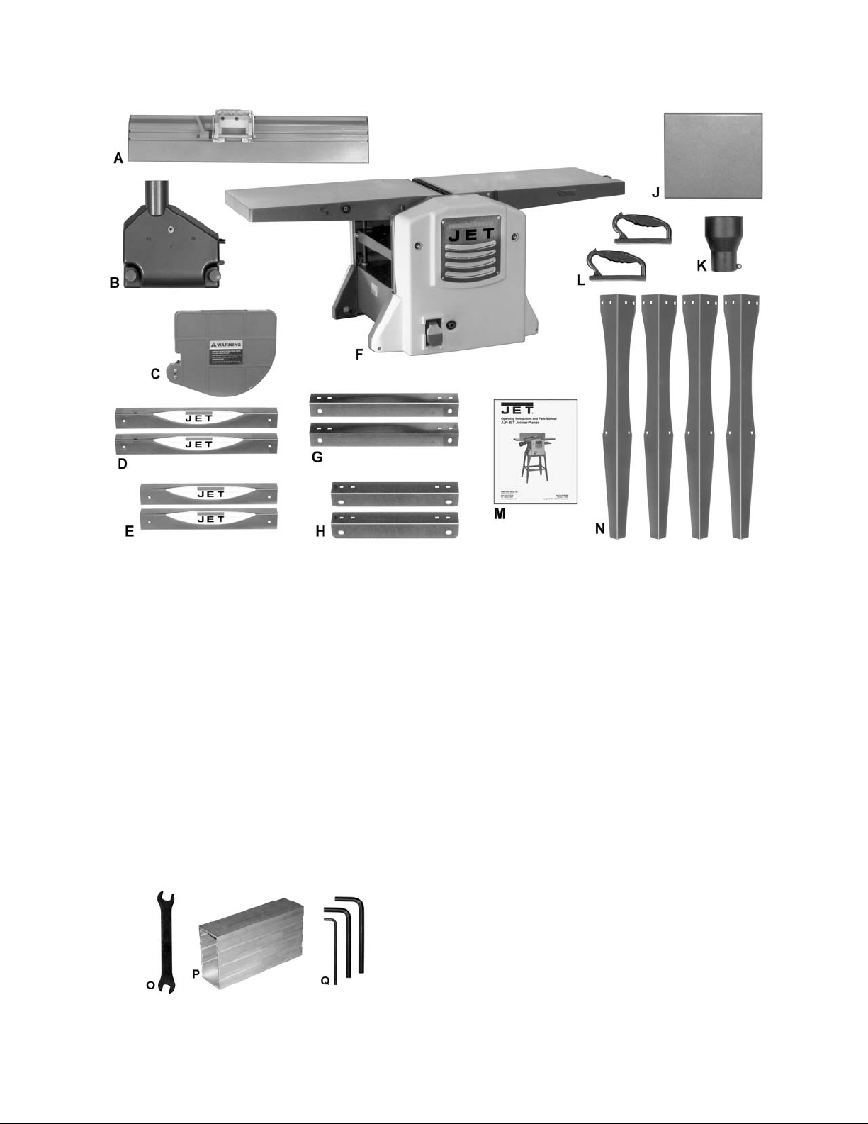
6.0 Shipping Contents
Figure 1 – Contents of the Main Car ton
7.0 Unpacking
Remove all contents from the shipping carton.
Do not discard the carton or packing material
until your Model JJP-10BT Jointer-Planer is
assembled and is runni ng satisfactorily.
Compare the c ontents of the carton agai nst the
list of parts shown on these pages. The letter
identification i n the li st corresponds to the it ems
shown in the Figures. This is your key for
identifying the parts used throughout the
Assembly section for easy reference.
Remove the protec tive coating that is appli ed to
the table with a household grease-and-spot
remover.
Figure 2 – Tools Included
Contents of the Main Carton
01 Jointer Fence – A 0
01 Dust Chute – B
01 Cutterhead Guard – C
02 Long Support Plate – D
02 Short Support Plate – E
01 Jointer-Planer – F
02 Long Stand Top Support – G
02 Short Stand Top Support – H
01 Planer Outfeed Table Extension – J
01 2-1/2" to 4" Hose Adapter – K
02 Push Block – L
01 Owner's Manual – M
04 Stand Leg – N
Tools Inc luded
01 8/10mm Open-end Wrench – O
01 Knife Setting Gauge (p/n JJP8BT-KSG) – P
01 3, 5, 6mm hex wrenches (set of 3) – Q
8
Page 9
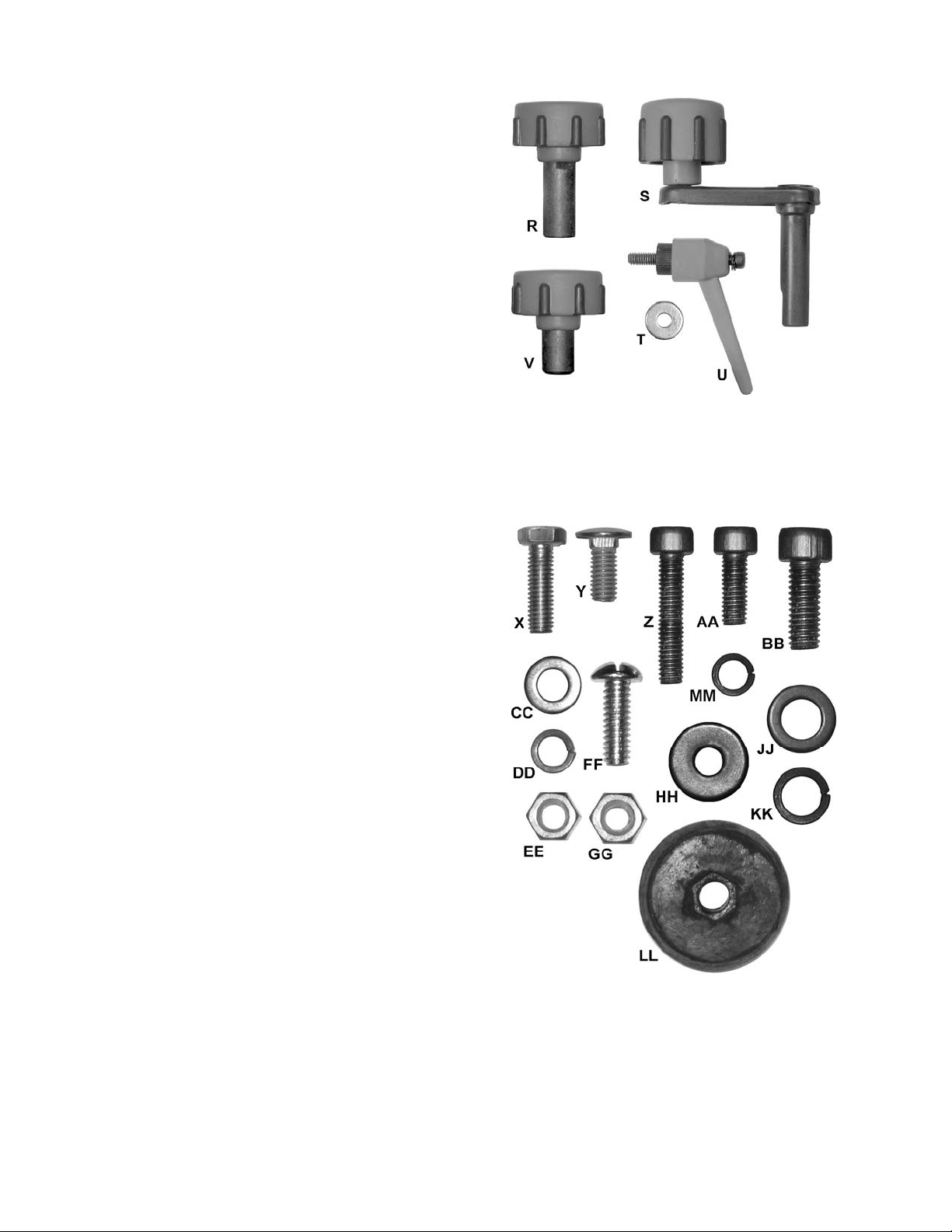
Knobs and Handles
01 Lock Knob (p/n JJP8BT-90L) – R
01 Elevating Handle (p/n JJP8BT-19A) – S
01 Locking Handle (p/n JJP8BT-25A) – U
01 Flat Washer – T
01 Lock Knob (p/n JJP8BT-90S) – V
Hardware Package (p/n JJP 10BT-HP)
Figure 3 – Knobs and Handles
Note: The index number in parentheses refers to
the same item as shown in the parts breakdowns.
4 Hex Cap Screw, M6x20 (#13, Stand Assbly) – X
24 Carriage Bolt, M6x12 (#9, Stand Assbly) – Y
02 Socket Head Cap Screw, M6x25 (#73) – Z
03 Socket Head Cap Screw, M6x10 (#15) – AA
04 Socket Head Cap Screw, M8x20 (#16, Stand
Assbly) – BB
28 Flat Washer, M6 (#8, Stand Assbly) – CC
24 Lock Washer, M6 (#7, Stand Assbly) – DD
28 Hex Nut, M6 (#6, Stand Assbly) – EE
02 Pan Head Machine Screw, M6x16 (#101) – FF
02 Hex Nut, M6 (#63) – GG
03 Flat Washer, M6 (#68) – HH
04 Flat Washer, M8 (#14, Stand Assbly) – JJ
04 Lock Washer, M8 (#15, Stand Assbly) – KK
04 Rubber Foot (#12, Stand Assbly) – LL
02 Lock Washer, M6 (#69) – MM
Figure 4 – Hardwar e Package #J J P 10BT- HP
(shown actual size)
9
Page 10
8.0 Assembly
For assembly convenience, the item letter
designators used throughout the Assembly section
are the same as those used to identify shipping
content and hardware components on pages 8–9.
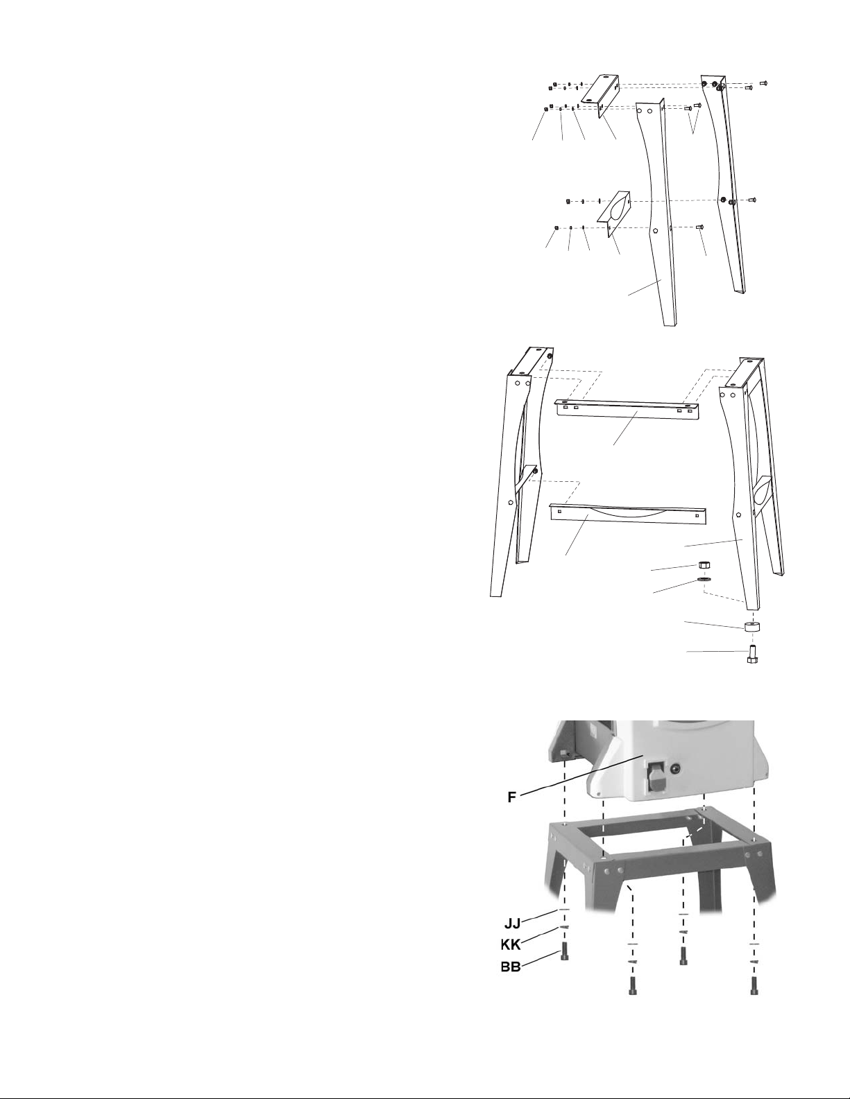
8.1 Stand assembly
Referring to Fi gur e 5:
1. Select two legs (N), one short st and top support
(H) and one short suppor t plat e (E).
2. Attach one end of the stand top support (H) to the
top of the first leg with two carriage bolts (Y), flat
washers (CC), lock washers (DD) and hex nuts
(EE). Attach the other end of the stand top
support (H) to the second leg in the same
manner. Hand-tighten only at this time .
3. Attach a support plate (E) to each leg (N) in the
same manner with two carriage bolts (Y), flat
washers (CC), lock washers (DD) and hex nuts
(EE). Hand-tighten only at this time.
4. Repeat steps 1–3 using the remaining legs,
short stand top support and support plate.
EE
EE
DD
DD
CC
CC
H
E
N
G
Y
Y
5. Complete the stand construction by attaching
long stand top supports (G) and long support
plates (D) to the leg assemblies constructed in
steps 1–4. Hand-tighten all hardware only at this
time.
6. Place a rubber foot (LL) on a hex cap screw (X),
then insert the threaded end of the screw through
the opening on the bottom of the leg.
7. Secure with flat washer (CC) and hex nut (EE).
8. Attach rubber feet t o remaining l egs in the sam e
manner.
9. Pl ace stand upri ght. Ensure that the stand i s on
a level surface and all four legs are contacting
the surface.
10. Tight en all hex nuts with the 10mm w rench (O)
provided.
8.2 Mounting Jointer-Planer to Stand
Referring to Fi gur e 6:
1. Place the Jointer-Planer (F) onto the assembled
stand and secure with 4 each socket head cap
screws (BB), loc k wa shers (KK), and flat washers
(JJ).
2. Tighten all socket head cap screws (BB) with
the 5mm hex wrench (Q) provided.
B
D
EE
CC
LL
X
Figure 5
Figure 6
10
Page 11
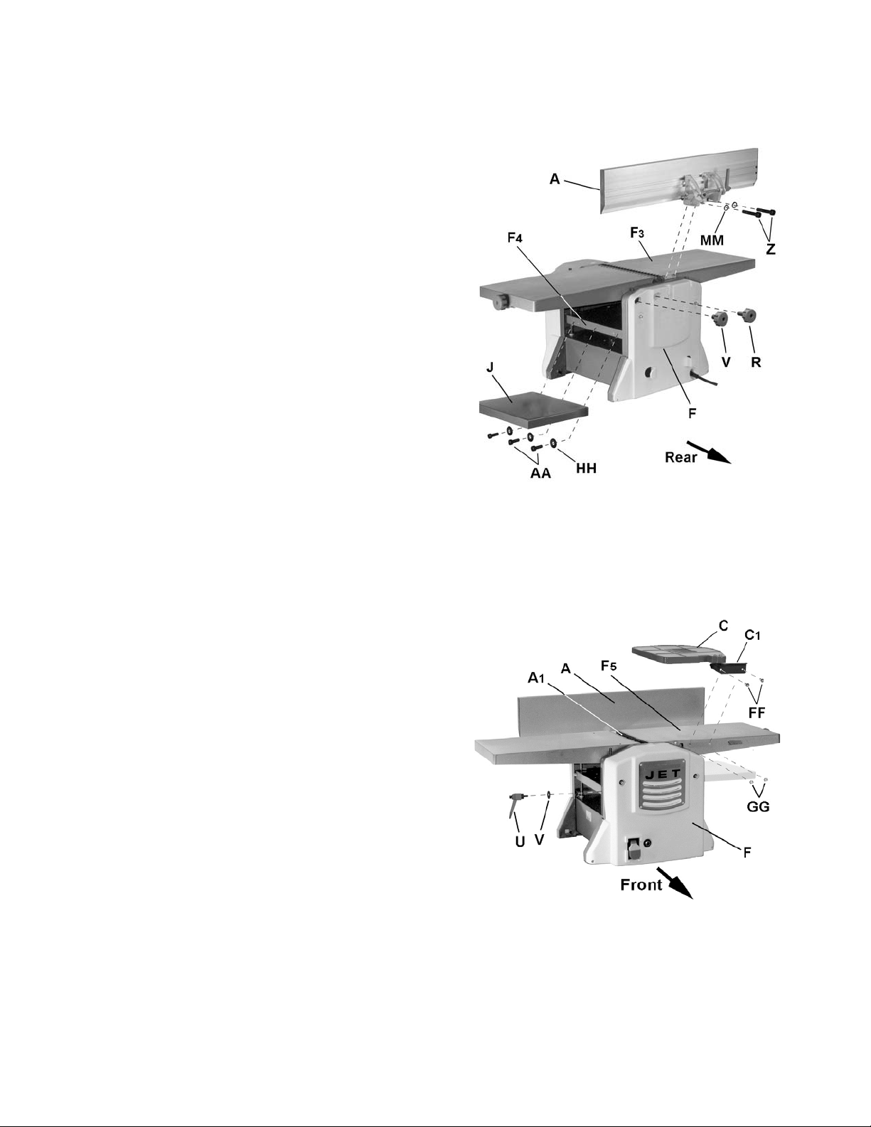
8.3 Jointer-Planer assembly
Referring to Fi gur e 7:
Fence
1. Attach jointer fence (A) to back of jointer outfeed
table (F
(Z) and lock washers (MM). Tighten screws with
5mm hex wrench (provi ded) .
Lock knobs
The JJP-10BT Jointer-Planer comes equipped with
two lock knobs to secure the posi tion of the jointer
infeed table.
2. Install jointer infeed table lock knobs (V, R).
Note: The shaft l ength of each lock knob (refer
to Figure 3) is different. Be sure to instal l each in
the correct location.
Extension table
3. Attach the pl aner outfeed extension t able (J) to
the main planer table (F
socket head cap screws (AA) and flat washers
(HH). Tight en screws with 5mm hex wrench.
Extension table adjustment
Two setscrews located underneath the extension
table (J ) are used to adj ust t he height positi on of t he
outer (protruding) edge, which must be slightly
higher than the main planer table (F
minimize snipe (see sect. 13.5, Avoiding Snipe).
4. Using a 4mm hex wrench, turn setscrews
slightly clockwise to raise the table or
countercl oc k wise to lower the table.
3) with two each socket head c ap s c r ews
4) with three each
4) in order to
Figure 7
Lock han dle
Referring to Fi gur e 8:
Attach planer table lock handle (U) a nd flat washer (T).
Cutterhead guard
5. Install cutterhead guard (C) by securing the
bracket (C
table (F
1) to the side of the jointer infeed
5) with two each pan head machine
screws (FF) and hex nuts (GG).
Important: It is extremely important that spring
action causes t he cutterguard (C) to r etract against
the fence (A), concealing the cutterhead (A
1). If
spring return t ensi on is not enough, adjust the spring
located on the cutter head pivot shaft accordi ngly .
Figure 8
11
Page 12
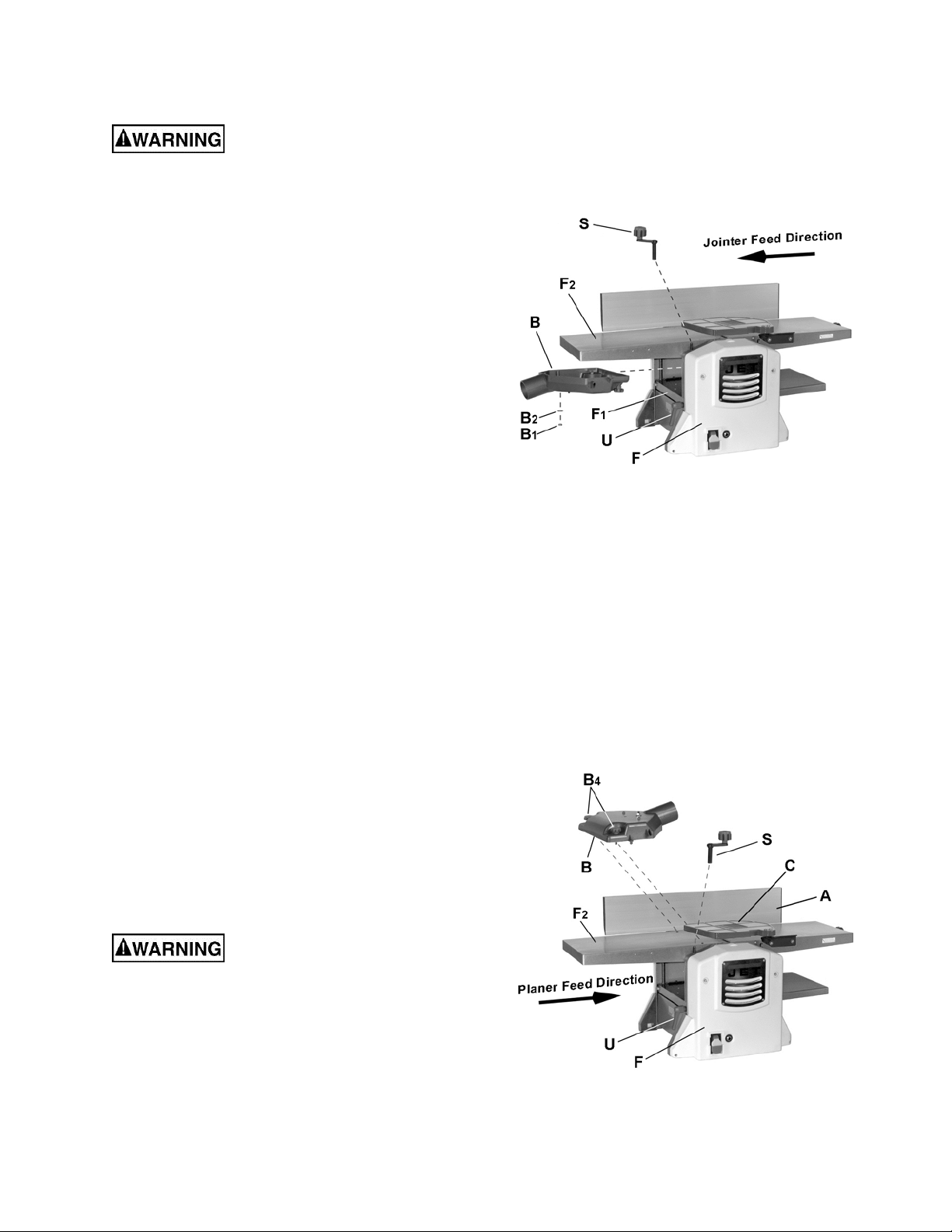
9.0 Jointer setup
Disconnect machine from power
source before making any adjustments. Failure
to comply may cause seriou s injury.
Referring to Fi gur e 9:
1. Loosen lock handle (U).
2. Install planer table height adjustment handle (S).
3. Turn handle (S) counterclockwise and lower
planer table (F
1) all the way.
4. Remove hex nut (B
1) and flat washer (B2) from
dust chute (B ).
5. Orient the dust chute (B) as shown and install
into the infeed opening.
Position the chute (B) such that the two
positioning keys and one threaded positioning
screw underneath t he chute meshes with three
positioning holes on the table (F
1).
6. Raise the table (turn handle S clockwise) until
the dust chute (B) is held firmly in place
between the planer inf eed table (F
outfeet table (F
2). Do not overtighten.
1) and jointer
7. Tighten lock handle (U).
Step 8 is optional.
8. Fur ther secure the dust c hute by rei nstalli ng the
hex nut (B
underneath the planer inf eed table (F
1) and flat washer (B2) from
1).
9. Remove handle (S).
10.0 Planer setup
Figure 9
Important: Dust chute (B) must be properly install ed in
both Jointer setup and Planer setup. If improper
install ation fails to activate a mic ro-switch, the machine
will not start .
If the machine is currently set up for jointer
operation, r emove the dus t chute (B, Fig. 9). Refer
to sect. 9.0, Jo i n te r Se tu p .
Referring to Fi gur e 10:
1. Swing cutterguard (C) away from fence (A),
which will expose the cutterhead.
Cutterhead knives are
dangerously sharp. Use extreme caution when
working around them. Failure to comply may
cause serious inj ury.
2. Orient the dust chute ( B) as shown. Instal l onto
the jointer outfeed table (F
tightening lock knobs (B
2) and secure by
4).
Figure 10
12
Page 13

11.0 Operating controls
Disconnect machine from power
source before making any adjustments. Failure
to comply may cause seriou s injury.
11.1 Power
Plug power cord into outlet.
Referring to Fi gur e 11:
Start/Stop
Pull the red switch (A) out to start. Push in to stop.
Safety key
Removing the safety key (B) will render the
start/stop switch inoperable. The machine can
continue to operate without the key, but upon
stopping cannot be restar ted until it is reinstall ed.
Reset switch
If the machine should com e to an unexpected stop
during operation due to overload or jammed workpiece, etc.:
1. Set the start/stop switch (A) to stop position
(pushed in).
2. Momentarily press, then release, the reset
switch (C).
3. Restart machine.
11.2 Planer controls and adjustments
Referring to Fi gur e 12:
11.2.1 Table lock
Turn the lock handle ( A ) c ounterclockwise to release
and permit table adjustment. Turn the lock handle
(A) clockwise to secure the planer table (D) in its
selected position.
11.2.2 Table height adjustment
The planer tabl e height is set as follows:
1. Unlock the table lock (A).
2. Install the removable adjustment handle (C)
onto the shaft (B).
3. Rotate the adjustment handle (C) clockwise to
raise the planer table (D), counterclockwise to
lower.
Each revolution of the adjustment handle (C) results
in a 3/32" up or down movement of the table (D). A
scale indicates the amount of table travel. The pointer
(E) indicates the table position on the scale relative to
the cutterhead.
Figure 11
Figure 12
13
Page 14

11.3 Jointer controls and adjustments
Refer to Figure 13.
11.3.1 Infeed table hei gh t adju st ment
Two lock knobs (F) and a height adjustment knob
(E) control t he height adjustment of the infeed table
(D).
To adjust:
1. Loosen lock knobs (F).
2. Turn the height adjustment knob (E) clockwise
to raise the inf eed table (D) or counter-c lockwise
to lower the table.
The amount of table adj ustment can be read on
the scale (C).
3. Tighten the lock knobs (F).
Note: A depth of cut of 1/16" or less is recom-
mended.
11.3.2 Cutterhead guard
Properly posi tioned, the cutterhead guard (A) should
rest against the fence (B
1).
11.3.3 Fence bevel adjustment
The fence (B
2) can be tilt ed backward (G) up to 45°
(that is, for a tot al incl uded angle of 135° f rom table
surface) as follows:
1. Loosen lock handle (J).
2. Tilt the fence (B
2) back to the desired angl e up
to 135 degrees (G). Or you can place your
beveled reference piece on the table and
against the fence, adjusting the fence until the
angle of the fence matches the bevel of your
gauge piece.
3. Tighten the lock handle (J).
Figure 13
14
Page 15

12.0 Adjustments
12.1 Cutterhead knife adjustment
Cutterhead knives are
dangerously sharp! Use extreme caution when
inspecting, removing, sharpening or replacing
knives into the cutterhead. Failure to comply
may cause serious injury!
Determining if adjustment is necessary:
1. Disconnect machine from the power source.
2. Remove the cutterhead guard.
Referring to Fi gur es 14 and 15:
Note: To rotate the cutterhead, the cutterhead
pulley must be turned. This requires removing the
panel on the front of t he cabi net for access.
3. Rotate the cutterhead (E) until one knife is i n the
12 o'clock posi tion. The 12 o'clock position is the
highest point a blade will reach i n the cutting ar c
(C, Fig. 15).
4. Place the knife set ting gauge ( J) on t he outfeed
table (F). One end of the gauge should be
positioned ov er the cutting knife (C) towards the
near end of the blade (G ).
Use care when han dling th e knife
setting gauge near the blades to prevent damage.
Note the positi on of the knife bl ade with respect
to the gauge, then m ove the gauge to the other
side of the table towards the fence (H) and
again note the position of the knife blade with
respect to the gauge.
The blade must be at the same height at each
end and must al so be at the sam e hei ght as the
outfeed tabl e (bottom of gauge). If thi s is not t he
case, adjustm ent is required as follows:
Adjustm e nt pr oc e dure
5. Slightly loosen seven gib lock screws (A) by
turning into the lock bar (B), clockwise as
viewed from the infeed table (K).
6. Adjust the blade height by turning jack screws
(D) upon which the blade rests. To lower the
blade, turn the screw clockwise. To raise, turn
the screw countercloc k wise.
7. When t he bl ade i s at the pro per h ei ght, al ternat el y
tighten the seven gib lock screws (A).
Repeat steps 3 – 7 to adjust the r em aining blade.
Figure 14
C
B
A
D
E
Figure 15
15
Page 16

Note: The most common cause for unsatisfactory
cutting perf ormance is improperly set kniv es. Many
aftermark et devices are av ailable t o f urther assist in
the accurate setting of knives.
12.2 Replacing cutter knives
Disconnect machin e from power
source before making any adjustments. Failure
to comply may cause seriou s injury.
1. Disconnect machine from the power source.
2. Remove the cutterhead guard.
Cutterhead knives are
dangerously sharp. Use extreme caution when
inspecting, removing, sharpening, or replacing
knives into the cutterhead. Failure to comply
may cause serious injury.
Referring to Fi gur es 14 and 15 (page 15):
3. Turn all seven gib lock screws (A) into the lock
bar (B) by turning in a clockwise direction as
viewed from the infeed table (K).
4. Carefully remove the cutter knife (C) and lock
bar (B).
5. Repeat for the remaining knife.
6. Thoroughl y clean all surfaces of t he cutterhead,
knife slots and loc k bar s of any dust or debris.
7. Insert the first replacement knife (C) into the
knife slot, making sure it faces the proper
direction.
8. Insert lock bar (B) and tighten just enough to
hold in place.
9. Repeat for the other blade.
Following installation, the knives must be adjusted
as described in sect. 12.1, Cutterhead Knife
Adjustment.
12.3 Jointer fence adjustment
Referring to Fi gur e 16:
The joint er fenc e (A) can be adj usted f rom a f ull for ward
position (90º t o table, corresponding t o a scale reading
of 0º) to a f ull back -tilted positi on of 135º (scale r eading
of 45º).
If setti ng to m aximum positions doe s not stop the f ence
at 0º or 90º, make adjustm ents as follows:
12.3.1 Fence 90º adju st ment
1. Loosen lock handle (H) and bring fence fully
forward. Using a square, determine if the fence is
90º to the table.
If adjustm ent is requi r ed:
2. Loosen j am nut (E) an d adjust stop screw (D) in or
out until a fence position of 90º with respect t o the
table is achieved.
3. Secure the jam nut (E).
Check the scale i ndicati on. If the indicator (C) does not
point to zero:
4. Loosen screw (B), adjust ac cordi ngl y, then r etight en
screw.
12.3.2 Fence 45º adju st ment
Verify that the fence and scal e indicat ion is accurat e at
90º as outlined in F enc e 90º Adjust m ent above.
1. Loosen lock handle (H) and set the fence all the
way back. Using a square, det ermi ne if the f ence i s
135º to the table.
If adjustm ent is requi r ed:
2. Loosen j am nut (G) and adjust stop screw (F) i n or
out until a f ence positi on of 135º wit h respect to t he
table is achieved. Note: The screw head stops
against the fence mounting bracket.
3. Secure the jam nut (G).
16
Figure 16
Page 17

12.4 Belt replacement
Refer to Figure 17 when installing or replacing the
feed-roller (A) or cutterhead dr iv e (D) belts.
Disconnect machin e from power
source before making any adjustments. Failure
to comply may cause seriou s injury.
12.4.1 Feed-Roller belt replacement
Cutterhead knives are
dangerously sharp. Use extreme caution when
replacing any belt. Contact with cutterhead
knives will cau se serio us injury.
1. Remove the front panel . Thi s is the panel where
the Start/Stop switch is located.
2. Remove feed-roller belt (A) from pulley (B) while
manually rot ating pulley (C).
When this is accomplished, belt will fall away
from pulley (C).
3. Loop the new belt around pulley (C), then
around pulley (B) while m anually rotati ng pulley
(C).
4. When installed, continue to manually rotate
pulley (C ) and v erify t hat belt is proper ly seated
on both pulleys.
5. Replace front cover.
12.4.2 Cutterhead d rive belt replacement
Cutterhead knives are
dangerously sharp. Use extreme caution when
replacing any belt. Contact with cutterhead
knives will cau se serio us injury.
The cutterhead drive belt should seldom if ever,
require repl acement. Follow the procedure below if,
however, the belt shoul d r equire replacement.
1. Remove the feed-roller belt as described in
Feed-Roller Belt Replacement above.
2. Remove the bottom portion of the cutterhead
drive belt (D) from pulley (E) while manually
rotating pulley (F).
Use extreme caution to avoid
contact with cutt erhead knives while performing
this step. Contact with cutterhead knives will
cause serious inj ury.
3. Rem ove top port ion of belt (D) f rom pulley (F),
then work it under the chai n and p ast pull ey (B)
to remove completely.
Figure 17
4. Install new belt by first feeding the lower loop
downward behind the gear ( H) and pulley (C). This
will properly position the lower loop of the belt in
close proximi ty to pulley (E).
5. Slide the top l oop of the bel t around and past pulley
(B), sliding it underneath and past chain (G); then
loop around pulley (F).
6. Loop belt around pulley (E) whil e manually rotating
pulley (F).
Use extreme caution to avoid
contact with cutterhead knives while performing this
step. Contact with cutterhead knives will cause
serious injury.
7. Manuall y rotate pull ey (F) to verif y that the groov es
in the belt are pr operly meshed with the gr ooves on
both pulley s.
This completes the c utt er head dr ive belt installati on.
8. Replace the feed-roller belt (Feed-Roller Belt
Replacement secti on steps 3–5).
17
Page 18

13.0 Basic Operations
13.4.2 Hand placemen t
13.1 Dust collection
Before initial operation, the machine must be
connected to a dust collector.
Important: If a dust collection system is not
used, the quality of your c ut will suffer severely.
13.2 Initial startup
After the assembly and adjustments are
complete the pl aner is ready to be tested. Plug
in and start the machine. Keep your finger on
the Stop button in case of a problem. The
machine should run smoothly with little or no
vibration or rubbing noises. Investigate and
correct the source of any problems before
further operation.
DO NOT attempt to
investigate or adjust the planer while it is
running. Wait until the mach ine is turn ed off,
unplugged and all working part s have come
to a complete standstill.
Always wear ANSI-approved
safety glasses or goggles when operating
equipment.
Never pass hands directly
over the cutterh ead.
Referring to Fi gur e 18:
At the start of the cut, the left hand holds the
workpiece firmly against the infeed table and
fence whil e the ri ght hand pushes the work piec e
in a smooth, even m otion t oward the cutt erhead.
After the cut is under way, the new surf ace r ests
firmly on the outfeed table. The left hand is
transferred to the outfeed side (Figure 18) and
presses down on this part of the workpiece, at
the same time maintaining flat contact with the
fence. The right hand presses the workpiece
forward, and before the right hand reaches the
cutterhead it should be moved to the work on
the outfeed tabl e.
13.4.3 Surfacing
The purpose of surfacing on a jointer is to
produce one flat surface (Fi gure 19). The other
side can then be milled to precise, final
dimensions on a thi ckness planer result ing in a
board that is smooth and f lat on both sides and
each side parallel to the other.
If the wood to be jointed is cupped or
bowed, place the concave side down, and
take light cuts unti l the surface is flat.
13.3 Changing mode of operation
When changing the operating mode (planer to
jointer and back) the machine must be turned off,
unplugged, and come to a complete stand-still.
To change the mode of operation, see sect . 9.0,
Jointer Setup and sect. 10.0, Planer Setup.
13.4 Jointer operations
13.4.1 Correct operating position
The operator must be positioned offset to the
infeed table (Figure 18).
Figure 18
Never surf ace pi eces shorter t han 12 inc hes
or thinner t han 3/8 inc h without the use of a
special work holding fixture.
Never surf ace pieces thinner than 3 inc hes
without the use of a push bloc k .
Cuts of approxim ately 1/ 16" or less at a tim e
are recommended, whic h provides for bett er
control over the material being surfaced.
More passes can then be m ade to r each the
desired depth.
Figure 19
18
Page 19

13.4.4 Dir e c tion of grai n
Avoid feeding work into the jointer against the
grain (Figur e 20) .
Figure 20
This may r esul t in chipped and splintered edges.
Feed with the grain to obtain a smooth surface,
as shown in Figure 21.
Figure 22
3. If the board is bowed (curved), place the
concave edge down on t he infeed table.
4. Set infeed table for a cut of approximately
1/16 inch.
5. Hol d the stock firmly agai nst the f ence and
table, feed t he stock slowly and evenly over
the cutter head.
13.4.6 Beveling
Beveling an edge is t he same operati on as edge
jointing, except that the fence is tilted to a
specified angle.
Make certai n material being bev eled is over
12 inches long, m ore than 1/ 4 inch thi ck and
1 inch wide.
Figure 21
13.4.5 Edge jointing
Jointing (or edging) is the process of creati ng a
finished, flat edge surface that is suitable for
joinery or finishing (Figure 22). It is also a
necessary step pri or to ri pping stock to width on
a table saw.
Never edge a board that is less than 3
inches wide, l ess than 1/4 i nch thick, or 12
inches long, without using a push block.
When edging wood wider t han 3 inches lap
the fingers over the top of the wood,
extending them back over the fence such
that they will act as a stop for the hands in
the event of a kickbac k.
When workpiece is twice the
length of the jointer infe e d or out fe ed table
use an infeed or outfeed support.
To edge:
1. Make sure the fence is set to 90°. Double
check it with a square.
2. Inspect stock for soundness and grain
direction (refer to sect. 13.4.4, Direction of
Grain).
To bevel:
1. Use a bev el gauge t o determine t he desired
angle. Then set the f enc e to t he same angle.
2. Inspect stock for soundness and grain
direction (refer to Direction of Grain on
previous page).
3. Set the infeed table for a cut of
approxim ately 1/16.
4. If the board is bowed (curved), place the
concave edge down on the i nfeed table.
5. Feed the stock through the cutterhead,
making sure the face of the stock is
completely flat against the fence and the
edge is making solid contact on the infeed
and outfeed tabl es (Figure 23).
For wood wider than 3 inches – hold with
fingers close together near the top of the
stock, lappi ng over the board and ex tending
over the fence.
For wood less than 3 inches wide – use
beveled push blocks and apply pressure
toward the fence. Keep fingers near top of
push block.
Several passes may be required to achieve full
bevel.
19
Page 20

Figure 23
13.5 Planer operations
13.5.1 Depth of cut
Thickness planing refe rs to the s izing of lumber to
a desired thickness while creating a level surface
parallel to the opposite side of the board. Board
thickness that the planer will produce is indicated
by the scale (see sect. 11.2.2, Table Height
Adjustment). Preset the planer to the desired
thickness of the finished workpiece using the
gauge. The depth-of-cut is adjusted by raising or
lowering the pl an er t a ble (D, Figure 12) using the
adjustable handle (C, F ig u re 12).
The quality of thickness plani ng depends on
the operator's judgment about the depth of
cut.
The depth of cut depends on the width,
hardness, dampness, grain direction and
grain struct ur e of t he wood.
The maxim um thickness of wood that can be
removed in one pass is 5/64" for planing
operations on workpieces up to 5-1/2” wide.
The workpiec e must be po sitioned away f rom
the center tab on the rollercase to cut 1/8”.
Make a test cut wit h a test piece and verif y
the thickness produced.
Check the accuracy of the test cut before
working on the finished product.
13.5.2 Precaution s
A thickness planer is a precision wood-
working machine and should be used on
quality lumber only.
Do not plane dirty boards; dirt and small
stones are abrasive and will wear out the
blade.
Remove nails and stapl es. Use the pl aner to
cut wood only.
Avoid knots. Heavily cross-grained wood
makes knots hard. K nots can come lose and
jam the blade. Any article that encounters
planer blades may be forcibly ejected from
the planer cr eating a risk of injury.
13.5.3 Preparing the wo rk
A thickness planer works best when the
lumber has at l east one fl at surface. Use a
jointer t o creat e a flat surf ac e.
Twisted or sev erely warped boards ca n jam
the planer. Ri p the lumber i n half to reduce
the magnitude of the warp.
The work should be fed into the planer i n the
same direction as the grain of the wood.
Sometimes t he wood will change directions
in the mi ddle of the board. I n such cases, if
possible, c ut the board in the middle so the
grain dir ection is correct.
The maximum thickness of wood that c an be
removed in one pass is 1/16” for planing
operations on workpi eces from 5-1/2” up t o
10" wide.
For optimum planing perform anc e, t he depth
of cut should be less than 1/16”.
The board should be planed with shallow
cuts until the work has a l evel si de. Once a
level surface has been created, flip the
lumber and create parallel sides.
Plane alternat e sides until the desired t hick-
ness is obtained. W hen half of the total cut
has been taken from each side, the board
will have a uniform, moisture content and
additional dr ying will not cause it to warp.
The depth of cut should be shallower when
the workpiece i s wider.
When planing hardwood, take light cuts or
plane the wood in thin widths.
Do not plane a board that is
less than 6" long. It is recommended that
when planing short boards you butt them
end to end to avoid kickback and reduce
snipe.
13.5.4 Feed ing the work
The planer is supplied with planer blades
mounted i n the cutt erhead. Feed di rection i s left
to right (see Figure 10). The planer feed is
automatic; it will vary slightly dependi ng on the
type of wood.
Preparation:
Feed rate refers to the rate at which the
lumber travels through the planer.
The operator i s respon sible for aligning t he
work so it will feed pr operl y .
Raise or lower the tabl e to get the depth of
cut desired.
20
Page 21

The surface t hat the planer pr oduces will be
smoother if a shall ower depth of cut is used.
Stand on the front si de of t he machine.
Boards longer than 24” should have
additional support from free standing
material stands. These can be purchased
from JET – Stock # 709207. See Optional
Accessories on page 7.
Planing:
1. Position the workpiece with the face to be
planed on top.
Note: Feed direction is left to right (see
Figure 10).
2. Turn the planer on.
13.5.5 Avoi ding Snip e
Snipe refer s to a depression at eit her end of the
board caused by an uneven force on the
cutterhead when t he work is ent ering or leav ing
the planer.
Snipe will occur when the boards are not
supported properl y or when only one feed rol ler
is in contact with the work at the beginning or
end of the cut.
Precauti ons for av oiding snipe:
Push the board up while feeding the work
until the outfeed roller starts advancing it .
Move to the rear and receive the planed
board by pushing it up when the i nfeed roller
looses contact with the board.
3. Rest the board end on t he infeed side of t he
table and direct t he boar d into the planer.
4. Slide the workpiece into the infeed side of
the planer until the infeed roller begins to
advance the workpiece.
5. Let go of the workpiece and allow the
automatic f eed to advance the workpiece.
6. Do not push or pull on the workpi ece. Move
to the rear and receive the planed lumber by
grasping it in the same manner that it was
fed.
To avoid the risk of injury
due to kickbacks, do not stand directly in
line with the front or rear o f the planer.
7. Do not grasp any portion of the board that
has not gone past the i nfeed roller.
8. Repeat this operation on all of the boards
that need to be the same thick ness.
When planing more than one board of the
same thickness, butt the boards together to
avoid snipe.
Make shallow cuts. Sni pe is more apparent
when deeper cuts are taken.
Feed the work i n the direction of the grain.
Work fed against the grain will have
chipped, splintered edges.
21
Page 22

14.0 Maintenance
14.1 Blade care
Blades are extremely sh arp!
Use caution when cleaning
or changing. Failure to comply may cause
serious injury!
The condition of the blades will affect the
precision of the cut. Observe the quality of
the cut that the machine produces to check
the conditi on of t he blades.
Dull blades will tear, rather than cut the
wood fibers and produce a fuzzy
appearance.
Raised grain will occur when dull blades
pound on wood that has varying density . A
raised edge will also be produced where the
blades have been nicked.
When gum and pitch collect on the blades,
carefully r emove with a strong solvent. F ailur e to
remove gum and pitch build up may result in
excessiv e fric tion, blade wear and overheating.
The infeed t able hei ght is set properl y when
the stone's surface is flush with the knife
bevel.
6. Keep the cutterhead from rotating by
grasping the cutterhead pulley while sliding
the stone back and forth across the table.
7. Tak e the same amount of passes for all two
blades.
When the bl ades hav e been sharpened and sti ll
are not cutt ing efficientl y, trying to touch up the
blades furt her will only c ause the formati on of a
second beveled edge. When this starts to
happen, it is tim e to replace bl ades with another
set. It i s recommended to keep a second set of
blades on hand so that they may be installed
while the first set is being professionally
sharpened.
When blades become dull, touc h up blades. See
sect. 14.2, Sharpening the Knives.
14.2 Sharpening the knives
Blades are extremely sh arp!
Use caution when handling.
Failure to compl y may cause seri ou s injury!
1. Disconnect the machine from the power
source.
2. Remove the blade guar d and belt cover.
3. To protect the infeed table from scratches,
partially cover the sharpening stone with
paper (Figur e 24).
4. Lay the stone on the infeed table.
5. Lower the infeed table and turn the
cutterhead by t urning the cutter head pulley.
Figure 24
15.0 Lubrication
Use a good grade of light grease on the
steel adjusti ng screws located in the raising
and lowering mechanisms of the work
tables.
The cutterhead ball bearings are lifetime
lubricated and need no further care.
22
Page 23

16.0 Troubleshooting the JJP-10BTOS
A
16.1 Performance Troubleshooting – Jointer
Trouble Probable Cause Remedy
Finished stock i s
concave on back
end.
Finished stock i s
concave on front end.
Chip out. Cutting against the grain. Cut with the grain whenever possible.
Fuzzy grain.
Cutterhead slows
while operating.
Knife is higher than outfeed table.
Outfeed table is higher than knife.
Dull knives. Sharpen or replac e k niv es.
Feeding workpiec e too fast. Use slower rate of feed.
Cutting too deeply. Make shallower cuts.
Knots, imperfections in wood.
Wood has high moistur e c ontent.
Dull knives. Sharpen or replac e k niv es/inserts.
Feeding workpiec e too quickly, or
applying too much pressure to
workpiece.
Align cutterhead k nives with outfeed
table. See sect. 12.1, Cutterhead
Knife Adjustment.
Align cutterhead k nives with outfeed
table. See sect. 12.1, Cutterhead
Knife Adjustment.
Inspect wood closely for
imperfections; use different stock if
necessary.
Allow wood to dry or use diff er ent
stock.
Feed more slowly, or appl y l ess
pressure to workpiece.
“Chatter” marks on
workpiece.
Uneven knife marks
on workpiece.
Set knives properl y as descri bed in
Knives incorr ectly set.
Feeding workpiec e too fast.
Cutting too deeply. Make shallower cuts.
Knives are nicked, or out of
alignment.
sect. 12.1, Cutt er head K nife
Adjustment . Check that k nife slots
are clean and free of dust or debri s.
Feed workpiece slowly and
consistently.
lign knives per sect . 12. 1,
Cutterhead Knife A djus tment.
Replace nick ed knives.
23
Page 24

16.2 Performance Troubleshooting – Planer
Trouble Probable Cause Remedy
Snipe
Note: Snipe can be
minimized but not
eliminated
Fuzzy Grain
Torn Grain
Rough/Raised Grain
Rounded, glossy
surface
Inadequate support of long boards. Support long boar ds with ex tension
rollers.
Dull knives. Sharpen knives.
Lumber not butt ed pr operl y . Butt end to end each pi ec e of stock
as they pass through.
Planing wood with high moisture
content.
Dull kniv es. Sharpen or replace.
Too heavy a cut. Adjust proper dept h of cut
Knives cutti ng against grain. Cut along the grain.
Dull knives. Sharpen knives.
Dull knives. Sharpen knives.
Too heavy a cut. Adjust proper dept h.
Moisture cont ent too high. Remove high moisture c ontent from
Dull knives. Sharpen or replac e k niv es.
Feed speed too slow. Increase speed.
Remove high moisture c ontent from
wood by drying.
wood by drying.
Uneven depth of cut
side to side.
Board thickness does
not match dept h of
cut scale.
“Chatter” marks on
workpiece.
Cutting dept h too shal low. Increase depth.
Planer bed rough or dir ty. Clean pitch and resi due, and wax
planer table.
Surface of feed rollers clogged. Clear residue chips off of rollers.
Knife in corr ectly set. Adjust knives.
Depth of cut scale incor r ec t.
Knives incorr ectly set.
Cutting too deeply. Make shallower cuts.
Adjust depth of cut scale.
Set knives properl y as descri bed in
sect. 12.1, Cutt er head K nife
Adjustment. Check that knife slots are
clean and free of dust or debr is.
24
Page 25

16.3 Mechanical Troubleshooting – Planer/Jointer
Trouble Probable Cause Remedy
Machine will
not start/
restart or
repeatedly
trips ci rcuit
breaker or
blo ws fuses.
No incoming
power.
Planer frequently
trips.
Building cir cuit
breaker trips or
fuse blows.
Motor failure. If electri c mot or i s suspect, have a qualified electrici an test t he
Dust chute not
seated properly
on either Jointer
Infeed or Planer
Table
1. Verify unit is connected to power and S tart/Stop switc h is in the
Start position (see sect. 11. 1, Power ).
2. Verif y unit is connected t o power. Set t he Start/Stop swit ch to
the Stop position, depress and release the reset switch, then
reset the Start/Stop switch to the Start position (see sect. 11.1,
Power).
One cause of overl oading trips, which are not electri c al i n nature,
is too heavy a cut. The solution is to take a lighter cut.
Verify that planer is on a circuit of correct size. If circ uit size is
correct, ther e is probably a loose electrical lead.
motor for function or take the machine to a service center and
have it tested.
Adjust the dust chute, making sure that the key on the dust chute
depresses the mic r o- switc h on machine.
25
Page 26

17.0 Parts
Ordering Replacement Parts
To order parts or reach our service departm ent, call 1-800-274-6848 Monday through Friday (see our
website for business hours, www.jettools.com). Having the Model Number and Serial Number of your
machine available when you call will allow us to serve you quickly and ac c ur ately.
17.1 Jointer/Planer – Parts List
Note: Parts without par t numbers are for reference only and cannot be pur c hased i ndividually.
Index No. Part No. Descrip tion Size Qty
1 ............... JJP8BT-1 .................Chain Support Bracket ........................................................................... 1
2 ............... JJP8BT-2 .................Sprocke t ................................................................................................ 1
3 ............... JJP8BT-3 .................E-Clip .................................................................Ø6 .......... .................... 1
4 ............... TS-2361051 .............Lo c k Washer ......................................................M5 ............................ 42
5 ............... TS-1540031 .............Hex Nut ..............................................................M5 .............................. 9
6 ............... TS-1550031 .............Fla t Washe r ........................................................M5 ............................ 2 2
7 ............... JJP8BT-7 .................Corner Sprocket .................................................................................... 4
8 ............... JJP10BT-8 ...............Chain .................................................................................................... 1
9 ............... JJP10BT-9 ...............Base ...................................................................................................... 1
10 ............. JJP8BT-10 ...............Infeed Pointer Label .............................................................................. 1
11 ............. TS-1502031 .............Socket Head Cap Screw .....................................M5x12 ........................ 3
12 ............. JJP8BT-12 ...............Driven Lead Screw ................................................................................ 3
13 ............. JJP8BT-13 ...............Drive Lead Screw .................................................................................. 1
14 ............. JJP10BT-14 .............Extension Table ..................................................................................... 1
15 ............. TS-1503021 .............Socket Head Cap Screw * ..................................M 6x10 ........................ 3
16 ............. J JP 8 BT- 1 6 ...............Crank Arm Bu shing ............................................................................... 1
18 ............. JJP10BT-18 .............Main Table ............................................................................................ 1
................. JJP8BT-1 9A.............Elevating Handle Assembly (incl udes #19,23,24) ................................... 1
19 ............. JJP8BT-19 ...............Crank Arm ............................................................................................. 1
20 ............. JJP8BT-20 ...............Guide Rail ............................................................................................. 2
21 ............. TS-1503041 .............Socket Head Cap Screw .....................................M6x16 ........................ 4
23 ............. JJP8BT-23 ...............Knob Screw ........................................................................................... 1
24 ............. JJP8BT-24 ...............Knob ..................................................................................................... 1
................. JJP8BT-2 5A.............Locking Handle Assembly (includes #25,44,45,75) ................................ 1
25 ............. JJP8BT-25 ...............Locking Handle ...................................................................................... 2
27 ............. TS-1532032 .............Pan Head Machine Screw ..................................M4x10 ........................ 3
28 ............. TS-2361041 .............Lock Was h e r ......................................................M4 .............................. 3
29 ............. JJP8BT-29 ...............Pointer................................................................................................... 1
31 ............. TS-1540021 .............Hex Nut ..............................................................M4 .............................. 2
32 ............. JJP8BT-32 ...............Cord Clamp ........................................................................................... 1
33 ............. TS-1532052 .............Pan H
34 ............. JJP8BT-34 ...............Cover .................................................................................................... 2
35 ............. JJP8BT-35 ...............Rear Support ......................................................................................... 1
36 ............. JJP8BT-36 ...............Self-Tapping Screw ............................................ST4.2x10 .................. 10
37 ............. JJP8BT-37 ...............Scale ..................................................................................................... 1
38 ............. TS-1502011 .............Socket Head Cap Screw .....................................M5x8 ........................ 13
39 ............. JJP8BT-39 ...............Power Cord Protector ............................................................................ 1
40 ............. JJP8BT-40 ...............Rear Support Cover ............................................................................... 1
41 ............. JJP8BT-41 ...............Pin......................................................................................................... 2
42 ............. JJP8BT-42 ...............Self-Tapping Screw ............................................ST4.2x20 .................... 4
43 ............. JJP8BT-43 ...............Power Cord ........................................................................................... 1
44 ............. JJP8BT-44 ...............Screw .................................................................................................... 2
45 ............. JJP8BT-45 ...............Spring.................................................................................................... 2
46 ............. TS-1550031 .............Flat Wash er ........................................................M5 .............................. 4
47 ............. TS-2331051 .............Cap Nut ..............................................................M5 .............................. 4
ead Machine Screw ..................................M4x16 ........................ 2
26
Page 27

Index No. Part No. Descrip tion Size Qty
48 ............. JJP8BT-48 ...............Thread Lock Bushing ............................................................................. 4
49 ............. TS-1540031 .............Hex Nut ..............................................................M5 .............................. 2
50 ............. JJP8BT-50 ...............Outfeed Table Spacer............................................................................ 4
51 ............. JJP8BT-51 ...............Infeed Table Spacer .............................................................................. 4
52 ............. JJP8BT-52 ...............Bearing.................................................................................................. 1
53 ............. JJP8BT-53 ...............Spring.................................................................................................... 2
54 ............. JJP8BT-54 ...............Bushing Block........................................................................................ 5
55 ............. JJP8BT-55 ...............Spring.................................................................................................... 1
56 ............. JJP10BT-56 .............Roller .................................................................................................... 2
57 ............. 707411 ....................Knife ...................................................................................................... 2
59 ............. JJP8BT-59 ...............Pin......................................................................................................... 4
60 ............. JJP10BT-60 .............Knife Gib ............................................................................................... 2
61 ............. JJP8BT-61 ...............Screw .................................................................................................. 1 4
62 ............. JJP10BT-62 .............Cutterhead ............................................................................................ 1
63 ............. TS-1540041 .............Hex Nut * ............................................................M6 .............................. 6
64 ............. JJP10BT-64 .............Outfeed Table........................................................................................ 1
65 ............. TS-1550021 .............Flat Wash er ........................................................M4 .............................. 3
66 ............. TS-1501041 .............Socket Head Cap Screw .....................................M4x12 ........................ 2
67 ............. JJP8BT-67 ...............Fence Support ....................................................................................... 1
68 ............. TS-1550041 .............Flat Wash er *......................................................M6 .............................. 8
69 ............. TS-2361061 .............Lock Was h e r * ....................................................M6 .............................. 9
70 ............. TS-1482021 .............Hex Cap S cr e w ..................................................M6x12 ........................ 2
71 ............. JJP8BT-71 ...............Fence Bracket ....................................................................................... 1
72 ............. JJP8BT-72 ...............Screw .................................................................................................... 2
73 ............. TS-1503061 .............Socket Head Cap Screw * ..................................M 6x25 ........................ 2
74 ............. JJP8BT-74 ...............Washer.................................................................................................. 6
75 ............. JJP8BT-75 ...............Locking Nut ........................................................................................... 2
76 ............. JJP8BT-76 ...............Angle Pointer ......................................................................................... 1
77 ............. JJP8BT-77 ...............Pin......................................................................................................... 1
78 ............. JJP8BT-78 ...............Shaft ..................................................................................................... 1
79 ............. JWBS10OS-110.......Carriage Bolt ......................................................M6x16 ........................ 1
80 ............. J JP 8 BT- 8 0 ...............Hex Cap Screw ..................................................M4x15 ........................ 2
81 ............. JJP8BT-81 ...............Angle Marked Fence Support ................................................................ 1
82 ............. JJP10BT-82 .............Fence .................................................................................................... 1
83 ............. JJP10BT-83 .............Hose Adapter ........................................................................................ 1
84 ............. JJP10BT-84 .............Knob ..................................................................................................... 2
85 ............. JJP10BT-85 .............Dust Chute ...........................................................................
86 ............. JJP8BT-3 .................E-Clip .................................................................Ø6 .............................. 2
87 ............. JJP8BT-87 ...............Pointer................................................................................................... 1
88 ............. JJP8BT-88 ...............Infeed Direction Label ............................................................................ 1
89 ............. TS-1533042 .............Pan Head Machine Screw ..................................M5x12 ........................ 3
................. JJP8BT-9 0L .............Lock Knob Assembly – Long (includes #90,185) .................................... 1
................. JJP8BT-9 0S.............Lock Knob Assembly – Short (i ncludes #90,188) ................................... 1
90 ............. JJP8BT-90 ...............Knob ..................................................................................................... 1
91 ............. JJP10BT-91 .............Adjusting Rod ........................................................................................ 1
92 ............. TS-1541031 .............Nylon Insert Lock Nut ............................................................................ 2
93 ............. JJP10BT-93 .............Shaft ..................................................................................................... 1
94 ............. JJP8BT-94 ...............Bracket .................................................................................................. 1
95 ............. JJP8BT-95 ...............Cushion Block ....................................................................................... 1
96 ............. JJP10BT-96 .............Cutterhead Guard .................................................................................. 1
97 ............. TS-2245081 .............Flat Head Screw .................................................M5x8 .......................... 2
98 ............. JJP8BT-98 ...............Post ....................................................................................................... 1
99 ............. JJP8BT-99 ...............Spring.................................................................................................... 1
100 ........... JJP8BT-100 .............Support Bracket ..................................................................................... 1
101 ........... TS-1534052 .............Pan Head Machine Screw * ................................M6x16 ........................ 2
102 ........... JJP8BT-102 .............Retaining Ring ....................................................................................... 1
103 ........... TS-2361081 .............Lock Wash e r ......................................................M8 .............................. 2
104 ........... TS-1504051 .............Socket Head Cap Screw .....................................M8x25 ........................ 2
................. 1
27
Page 28

Index No. Part No. Descrip tion Size Qty
107 ........... JJP10BT-1 07 ...........Shield .................................................................................................... 1
108 ........... JJP10BT-1 08 ...........Shaft ..................................................................................................... 1
109 ........... JJP8BT-109 .............Washer................................................................................................ 29
110 ........... JJP8BT-110 .............Anti-Kickback Finger ............................................................................ 56
111 ........... JJP8BT-111 .............Bearing Cover ....................................................................................... 1
112 ........... JJP8BT-112 .............Bearing...............................................................6000-2Z ...................... 1
113 ........... JJP8BT-113 .............Front Support ........................................................................................ 1
114 ........... JJP8BT-114 .............Cut Depth Scale Label ........................................................................... 1
115 ........... JJP8BT-115 .............Spring.................................................................................................... 1
116 ........... TS-1502021 .............Socket Head Cap Screw .....................................M5x10 ........................ 6
117 ........... JJP8BT-117 .............Switch Mount ......................................................................................... 1
118 ........... JJP8BT-118 .............Switch ................................................................................................... 1
119 ........... JJP8BT-119 .............Pulley .................................................................................................... 1
120 ........... JJP8BT-120 .............Belt.....................................................................5PJ604 ....................... 1
121 ........... JJP8BT-121 .............Spacer................................................................................................... 1
122 ........... JJP8BT-122 .............Sprocket ................................................................................................ 2
123 ........... JJP8BT-123 .............Socket Head Cap Screw .....................................M6x15 ........................ 2
124 ........... JJP8BT-124 .............Drive Chain ........................................................(P=12.7)36 ................. 1
125 ........... JJP8BT-125 .............Gear ...................................................................................................... 1
126 ........... JJP8BT-126 .............Pulley .................................................................................................... 1
127 ........... TS-1533062 .............Pan Head Machine Screw ..................................M5 x20 ........................ 3
128 ........... JJP8BT-128 .............Key........................................................................................................ 1
129 ........... JJP8BT-129 .............Belt........................................................................................................ 1
130 ........... JJP8BT-130 .............Shaft ..................................................................................................... 2
131 ........... JJP8BT-131 .............Front Support Cover .............................................................................. 1
132 ........... JJP8BT-132 .............JET Nameplate ...................................................................................... 1
133 ........... JJP8BT-133 .............Key........................................................................................................ 1
134 ........... JJP8BT-134 .............Washer.................................................................................................. 1
135 ........... JJP8BT-135 .............Sprocket ................................................................................................ 1
136 ........... JJP8BT-136 .............Square Spacer ...................................................................................... 1
137 ........... JJP8BT-137 .............Gear ...................................................................................................... 1
138 ........... JJP8BT-138 .............Gear Bracket ......................................................................................... 1
139 ........... JJP8BT-139 .............Spring.................................................................................................... 1
140 ........... JJP8BT-140 .............Key........................................................................................................ 1
141 ........... JJP8BT-141 .............Pan Head Machine Screw ..................................M3x18 ........................ 2
142 ........... TS-2361031 .............Lock Wash e r ......................................................M3 .............................. 2
143 ........... TS-1550011 .............Flat Washer ........................................................M3 .............................. 2
144 ........... JJP8BT-144 .............Wire Clamp ........................................................................................... 1
145 ........... JJP8BT-145 .............Wire ...................................................................................................... 1
146 ........... JJP8BT-146 .............Motor Pulley .......................................................................................... 1
147 ........... JJP8BT-147 .............Screw .................................................................................................... 1
148 ........... JJP8BT-148 .............Bracket .................................................................................................. 1
149 ........... JJP8BT-149 .............Washer.................................................................................................. 1
150 ........... TS-2361081 .............Lock Wash e r ......................................................M8 .............................. 1
151 ........... JJP8BT-151 .............Socket Head Cap Screw .....................................M8x15 ........................ 1
152 ........... JJP8BT-152 .............Motor ..................................................................................................... 1
153 ........... JJP8BT-153 .............Cover .................................................................................................... 2
154 ........... JJP8BT-154 .............Star Washer .......................................................M4 .............................. 1
155 ........... JJP8BT-155 .............Strain Relief ........................................................................................... 2
156 ........... JJP8BT-156 .............Switch Box ............................................................................................ 1
157 ........... TS-1533032 .............Pan Head Machine Screw ..................................M5 x10 ........................ 2
158 ........... JJP8BT-158 .............Overload Switch .................................................6 A .............................. 1
159 ........... JJP8BT-159 .............Switch Box Cover .................................................................................. 1
160 ........... JJP8BT-160 .............Self-Tapping Screw ............................................ST4.2x15 .................... 4
161 ........... JJP8BT-161 .............Nut ........................................................................................................ 1
162 ........... JJP8BT-162 .............On/Off Switch ........................................................................................ 1
................. JJP8BT-162-1 ..........Switch Safety Key (not shown) .............................................................. 1
163 ........... JJP8BT-163 .............Shaft ..................................................................................................... 1
28
Page 29

Index No. Part No. Descrip tion Size Qty
164 ........... JJP10BT-1 64 ...........Infeed Table .......................................................................................... 1
165 ........... TS-1521051 .............Set Screw ...........................................................M4 x12 ........................ 2
166 ........... ................................Cord Clamp ................................................................... ........................ 1
167 ........... ................................Motor Housing ....................................................................................... 1
168 ........... JJP8BT-168 .............Brush Holder ......................................................................................... 2
169 ........... JJP8BT-169 .............Brush .................................................................................................... 2
170 ........... JJP8BT-170 .............Brush Cap ............................................................................................. 2
171 ........... ................................Bearing....................................................................... ........................... 1
172 ........... ................................Inductor ................................................................................................. 1
173 ........... ................................Stator Insula tion Pan ............................................................................. 1
174 ........... ................................Armature ............................................................................................... 1
175 ........... ................................Stator .................................................................................................... 1
176 ........... ................................Stator Insula tion Pan ............................................................................. 1
177 ........... ................................Self-Tapping Screw ............................................ST5 x56....................... 2
178 ........... JJP8BT-178 .............Fan........................................................................................................ 1
179 ........... ................................Bearing....................................................................... ........................... 1
180 ........... JJP8BT-180 .............Motor Cover .......................................................................................... 1
181 ........... JJP8BT-181 .............Switch Box Faceplate ............................................................................ 1
182 ........... JJP8BT-182 .............Jack Screw ............................................................................................ 4
183 ........... JJP8BT-183 .............Rivet ...................................................................Ø3x10 ........................ 4
185 ........... JJP8BT-185 .............Lock Shaft 1 (Long) ............................................................................... 1
186 ........... JJP10BT-186 ...........Fence End Cover 1 ................................................................................ 1
187 ........... JJP10BT-187 ...........Fence End Cover 2 ................................................................................ 1
188 ........... JJP8BT-188 .............Lock Shaft 2 (Short) ............................................................................... 1
189 ........... JJP10BT-1 89 ...........Rod ....................................................................................................... 2
190 ........... JJP8BT-19 0 .............Cord Clamp ........................................................................................... 1
................. 708815 ....................Push Block (not shown) ......................................................................... 2
................. JJP8BT-K SG ...........Knife/Blade Setting Gauge (not shown).................................................. 1
................. JJP10BT- HP ............Hardw are Package (*) .............................................................................
Note: Some parts may be listed f or r eference, but are only available as part of a larger assembly.
* Items with asterisk are included in JJP10BT-HP (Hardware Package).
29
Page 30

17.2 10" JOINTER-PL ANER ASSEMBLY DRAWING INDEX
30
Page 31

17.3 Planer Table Assembly
31
Page 32

17.4 Motor
17.5 Front Frame Assembly
32
Page 33

17.6 Chain Drive Assembly
17.7 Front Cover Assembly
33
Page 34

17.8 Cutterhead Guard Assembly
17.9 Dust Cover Assembly
34
Page 35

17.10 Jointer Infeed Table Assembly
17.11 Jointer Outfeed Table Assembly (10")
35
Page 36

17.12 Cutter Head/Feed Roller Assembly
17.13 Jointer Fence Assembly
36
Page 37

17.14 Rear Frame and Cover Assembly
37
Page 38

17.15 Jointer/Planer Stand
Index No. Part No. Descrip tion Size Qty
1 ............... JJP10BT-901 ...........Stand Top Support, S hort ...................................................................... 2
2 ............... JJP10BT-902 ...........Leg ........................................................................................................ 4
3 ............... JJP10BT-903 ...........Support Plate, Long ............................................................................... 2
4 ............... JJP10BT-904 ...........Support Plate, Short .............................................................................. 2
5 ............... JJP10BT-905 ...........Stand Top Support, Long ....................................................................... 2
6 ............... TS-1540041 .............Hex Nut * ............................................................M6 ............................ 24
7 ............... TS-2361061 .............Lo c k Washer * ....................................................M6 ............................ 24
8 ............... TS-1550041 .............Fla t Washe r *......................................................M6 ............................ 24
9 ............... 708315-63 ...............Carriage Bolt * ....................................................M6x12 ...................... 24
10 ............. TS-1540041 .............Hex Nut ..............................................................M6 .............................. 4
11 ............. TS-1550041 .............Flat Wash er ........................................................M6 .............................. 4
12 ............. JJP10BT-9 12 ...........Rubber Foot * ........................................................................................ 4
13 ............. TS-1482041 .............Hex Cap Screw * ................................................M6x20 ........................ 4
14 ............. TS-1550061 .............Flat Wash er *......................................................M8 .............................. 4
15 ............. TS-2361081 .............Lock Was h e r * ....................................................M8 .............................. 4
16 ............. TS-1504041 .............Socket Head Cap Screw * ..................................M 8x20 ........................ 4
* Items with asterisk are included in JJP10BT-HP (Hardware Package).
38
Page 39

18.0 Electrical Connection
0.33uF/275V
Start
Stator
Stator
C
Rotor
Rotor
Stop
M
1~
E
(Yellow and green wire)
Power Switch
Switch
Power Cord Plug
Overload Switch
L
N
Outlet
E
39
Page 40

427 New Sanford Road
LaVergne, Tennessee 37086
Phone: 800-274-6848
www.jettools.com
40
 Loading...