

Page 1
Assembly Instructions and Parts Manual
Taper Attachment Kit for GHW Lathes
Model TAK-GHW
JET
427 New Sanford Road
LaVergne, Tennessee 37086 Part No. M-321520
Ph.: 800-274-6848 Revision B 03/2014
www.jettools.com Copyright © 2014 JET
Page 2

Warranty and Service
JET warrants every product it sells against manufacturers’ defects. If one of our tools needs service or repair, please
contact Technical Service by calling 1-800-274-6846, 8AM to 5PM CST, Monday through Friday.
Warranty Period
The general warranty lasts for the time period specified in the literature included with your product or on the official
JET branded website.
• JET products carry a limited warranty which varies in duration based upon the product. (See chart below)
• Accessories carry a limited warranty of one year from the date of receipt.
• Consumable items are defined as expendable parts or accessories expected to become inoperable within a
reasonable amount of use and are covered by a 90 day limited warranty against manufacturer’s defects.
Who is Covered
This warranty covers only the initial purchaser of the product from the date of delivery.
What is Co vered
This warranty covers any defects in workmanship or materials subject to the limitations stated below. This warranty
does not cover failures due directly or indirectly to misuse, abuse, negligence or accidents, normal wear-and-tear,
improper repair, alterations or lack of maintenance.
Warranty Limitations
Woodworking products with a Five Year Warranty that are used for commercial or industrial purposes default to a
Two Year Warranty. Please contact Technical Service at 1-800-274-6846 for further clarification.
How to Get Technical Support
Please contact Technical Service by calling 1-800-274-6846. Please note that you will be asked to provide pro of
of initia l p u rch a s e whe n calling. If a product requires further inspection, the Technical Service representative will
explain and assist with any additional action needed. JET has Authorized Service Centers located throughout the
United States. For the name of an Authorized Service Center in your area call 1-800-274-6846 or use the Service
Center Locator on the JET website.
More Informa t io n
JET is constantly adding new products. For complete, up-to-date product information, check with your local distributor
or visit the JET website.
How S tate Law Applies
This warranty gives you specific legal rights, subject to applicable state law.
Limitations on This Warranty
JET LIMITS ALL IMPLIED WARRANTIES TO THE PERIOD OF THE LIMITED WARRANTY FOR EACH PRODUCT.
EXCEPT AS STATED HEREIN, ANY IMPLIED WARRANTIES OF MERCHANTABILITY AND FITNESS FOR A
PARTICULAR PURPOSE ARE EXCLUDED. SOME STATES DO NOT ALLOW LIMITATIONS ON HOW LONG AN
IMPLIED WARRANTY LASTS, SO THE ABOVE LIMITATION MAY NOT APPLY TO YOU.
JET SHALL IN NO EVENT BE LIABLE FOR DEATH, INJURIES TO PERSONS OR PROPERTY, OR FOR
INCIDENTAL, CONTINGENT, SPECIAL, OR CONSEQUENTIAL DAMAGES ARISING FROM THE USE OF OUR
PRODUCTS. SOME STATES DO NOT ALLOW THE EXCLUSION OR LIMITATION OF INCIDENTAL OR
CONSEQUENTIAL DAMAGES, SO THE ABOVE LIMITATION OR EXCLUSION MAY NOT APPLY TO YOU.
JET sells through distributors only. The specifications listed in JET printed materials and on official JET website are
given as general information and are not binding. JET reserves the right to effect at any time, without prior notice,
those alterations to parts, fittings, and accessory equipment which they may deem necessary for any reason
whatsoever. JET
Product Listing with Warranty Period
90 Days – Parts; Consumable items; Light-Duty Air Tools
1 Year – Motors; Machine Accessories; Heavy-Duty Air Tools; Pro-Duty Air Tools
2 Year – Metalworking Machinery; Electric Hoists, Electric Hoist Accessories; Woodworking Machinery used
for industrial or commercial purposes
5 Year – Woodworking Machinery
Limited Lifetime – JET Parallel clamps; VOLT Series Electric Hoists; Manual Hoists; Manual Hoist
Accessories; Shop Tools; Warehouse & Dock products; Hand Tools
NOTE: JET is a division of JPW Industries, Inc. References in this document to JET also apply to JPW Industries,
Inc., or any of its successors in interest to the JET brand.
®
branded products are not sold in Canada by JPW Industries, Inc.
2
Page 3
Assembly
Note: numbers in parentheses (#) refer to t he
exploded view and part s li st.
1. Remove the splash guard from the backside
of the lathe.
2. Remove the taper att ac hm ent f r om the box .
3. Remove the dust cover (29) held in place
with six screws (5).
4. Loosen and remove gib screws (16 & 24) .
Do not adjust or rem ov e gib screw (24A);
this will aid assembly when putting the taper
attachment together.
5. Remove the longitudinal slide assembly (6 &
11) from the slide base.
6. Thoroughly cl ean all par ts of the taper
attachment wi th cleaning solvent.
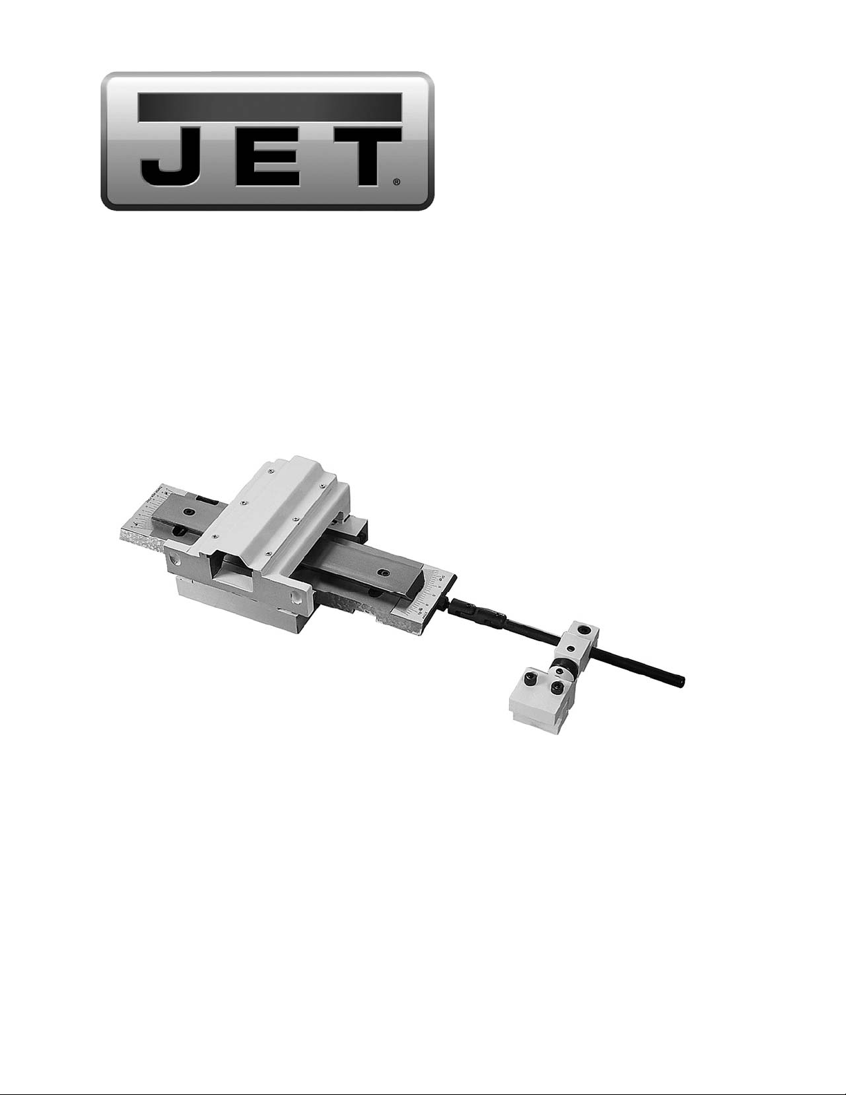
7. Remove two nuts (A, Figur e 1) and the
bearing cap (B, Fi gur e 1) fr om the end of the
cross slide screw (C, Figure 1)
8. Remove the thrust bear ing assembly from
the cross feed screw.
9. Remove two hex socket c ap screws (D,
Figure 1) and the block (E, Figur e 1) .
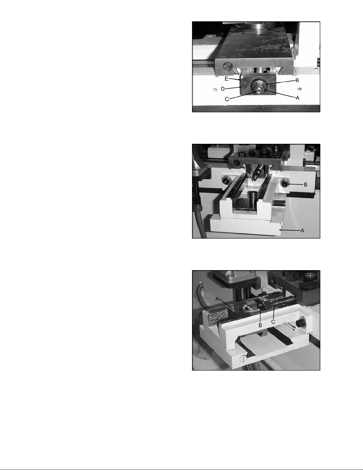
10. Attach the main body (A, Figure 2) to the
carriage wit h two M8 x 30 hex socket cap
screws, and two M8 fl at washers (B, Figure
2). Tighten the hex cap screws to hol d the
main body in place but l oose enough to
allow adjustment with a dead blow hammer,
or rubber mallet.
11. Pl ac e the cr oss sli de block (A, Figure 3)
onto the taper sli de r est ( 22) .
12. Posit ion the main body so that the hole in
the cross slide bloc k (B, Figure 3) lines up
with the cross slide screw (C, Figure 3).
13. Push the cros s slide block to engage the
cross slide screw through the hole in the
slide. It is important to get the slide to pass
over the cross slide screw sm oothly. Use a
rubber mallet , or a dead blow hammer to
position t he m ain body so that the slide
passes smoothly ov er the c r oss sli de screw
without lifting it.
Figure 1
Figure 2
Figure 3
3
Page 4

14. Make sure the inner bearing assembly is in
place before r e- assembly, no spacer. The
smaller, i nner diam eter bearing goes on first.
15. Pl ac e the longitudinal slide (A, Figure 4) int o
the main body.
16. Using a di al indicator with a magnetic base
(B, Figure 4) attached to the lathe bed, level
the longitudinal slide to the bed. The slide
assembly is level when it is less than .005”
from end to end. Keep the cross slide block
centered on the lead screw. Use a rubber
mallet, or a dead blow hamm er to position
the main body so that the cross slide block
passes smoothly ov er the lead screw and
that the longitudinal slide is level.
Note: repeat steps 13 & 16 until the longitudinal
slide is level and t he cross slide block passes
smoothly over the cr oss slide scr ew.
17. Tighten two M10 x 30 hex socket cap
screws that hol d the main body in plac e.
18. Re-check the longitudinal slide for level.
19. Clean and lightly oil all gib surfaces that
were previously r em ov ed.
20. Replac e the taper slide, gibs and gib
screws.
21. Check t o m ak e sure the slide moves easily
and without excessive play.
22. Replac e the outer bearing assembly (A,
Figure 5). The smaller inner diam eter
bearing goes on fir st.
23. Install two hex nuts (B, Figure 5). Tighten
the inner nut fir st to snug up the bearing
assembly. Turn the cross slide handle and
check for smooth r otati on. Tighten the jam
nut to hold the adjustment.
Figure 4
Figure 5
Note: It is not necessary, but a good idea to drill
and pin the taper i n plac e through the slide
bracket (3N).
24. Replac e the dust cover.
25. Thread the lock down linkage (A, Figure 6)
into the end of the slide assembly (B, Figure
6).
26. Pl ac e the clam p ( C , Fi gur e 6) onto the lathe
bed and tighten two hex socket cap screws
(D, Figure 6).
27. Line up the hole in clamp with the lock down
linkage (E, Figur e 6) and insert . Tighten the
hex socket cap screw (F, Fi gur e 6).
Figure 6
4
Page 5

28. Using a di al indicator mounted to the
carriage indicate along the tool post, while
moving the carriage, (Figure 7). You are
checking t o see that t he taper sli de is
parallel to t he m ov ement of t he carriage.
Note: You will need to loosen hex socket c ap
screws (12 & 13). This will allow you to turn the
adjusting screw (18).
29. When the taper slide is parallel make sure
the screws (12 & 13) are tight , and mar k the
zero point with a chisel .
• These taper attac hm ents are designed and
intended for use by pr oper ly trained and
experienced personnel only. If you are not
familiar with the proper and safe operation of
a taper attac hm ent, do not use until proper
training and knowledge have been obtained.
• Tighten the clam p br ac k et (59N) only when
using the taper at tachment. You may want
to remove the clamp brac k et when not using
the taper attachm ent.
Figure 7
Replacement Parts
To order parts or reach our ser vice department, call 1-80 0-274-6848 Mo nday through Frida y, 8:00 a.m. to 5:00
p.m. CST. Having the Model Number and Serial Number of your machine available when you call will allow us
to serve you quickly and accurately.
5
Page 6

TAK-GHW Taper Attachment Kit – Exploded View
6
Page 7

TAK-GHW Taper Attachment Kit – Parts List
Index No Part No Description Size Qty
1 ................ TAK1340A-1.............. Slide Base................................................................ ...................................... 1
2 ................ TS-1504081 .............. Hex Socket Cap Screw ............................................ M8 x 40 ......................... 4
3N .............. TAK1340W-3N .......... Slide Bracket............................................................ ...................................... 1
4 ................ TS-1504061 .............. Hex Socket Cap Screw ............................................ M8x 30 .......................... 2
5 ................ TAK1340A-5.............. Screw ....................................................................... M5x 8 ............................ 6
6 ................ TAK1340A-6.............. Longitudinal Slide .................................................... ...................................... 1
7 ................ 84-0004-00 ................ Taper Indicator Plate ............................................... ...................................... 1
8 ................ TAK1340A-8.............. Rivet......................................................................... ...................................... 2
9 ................ TAK1340A-9.............. Angle Indicator Plate................................................ ...................................... 1
10 .............. TAK1340A-10............ Rivet......................................................................... ...................................... 2
11 .............. TAK1340A-11............ Taper Slide .............................................................. ...................................... 1
12 .............. TS-1503031 .............. Hex Socket Cap Screw ............................................ M6 x 12 ......................... 1
13 .............. TS-1503051 .............. Hex Socket Cap Screw ............................................ M6 x 20 ......................... 1
14 .............. TAK1340A-14............ Axle .......................................................................... ...................................... 1
15 .............. TAK1340A-15............ Gib Strip ................................................................... ...................................... 1
16 .............. TAK1340A-16............ Adjusting Screw ....................................................... ...................................... 2
17 .............. TAK1340A-17............ Adjusting Nut ........................................................... ...................................... 1
18 .............. TAK1340A-18............ Adjusting Screw ....................................................... ...................................... 1
19 .............. TAK1340A-19............ Adjusting Knob......................................................... ...................................... 1
20 .............. TAK1340A-20............ Spring Pin ................................................................ 3 x 14 ............................ 1
21 .............. 84-0013-00 ................ Clamping Plate ........................................................ ...................................... 1
22 .............. TAK1340A-22............ Taper Slide Rest ...................................................... ...................................... 1
23 .............. TAK1340A-23............ Gib Strip ................................................................... ...................................... 1
24 .............. TAK1340A-24............ Adjusting Screw ....................................................... ...................................... 1
24A ............ TAK1340A-24............ Adjusting Screw ....................................................... ...................................... 1
25 .............. TAK1340A-25............ Cross Slide Block..................................................... ...................................... 1
26 .............. TS-1503051 .............. Hex Socket Cap Screw ............................................ M6 x 20 ......................... 2
27 .............. TAK1340A-27............ Feed Block ............................................................... ...................................... 1
29 .............. TAK1340A-29............ Dust Cover ............................................................... ...................................... 1
50 .............. TAK1340A-50............ Universal Joint (includes #52,54)............................. ...................................... 1
51 .............. TAK1340A-51............ Spring Pin ................................................................ 4 x 19 ............................ 2
52 .............. TAK1340A-52............ Universal Joint (re: TAK1340A-50) .......................... ...................................... 1
53 .............. TAK1340A-53............ Hex Nut .................................................................... ...................................... 1
54 .............. TAK1340A-54............ Adjusting Shaft (re: TAK1340A-50) ......................... ...................................... 1
55 .............. TAK1340A-55............ Lock Block ............................................................... ...................................... 1
56 .............. TS-1524011 .............. Set Screw ................................................................ M8 x 8 ........................... 1
57 .............. TS-1504041 .............. Hex Socket Cap Screw ............................................ M8 x 20 ......................... 1
58 .............. TAK1340A-58............ Eccentric Shaft......................................................... ...................................... 1
59N ............ TAK1340W-59N ........ Clamp Bracket ......................................................... ...................................... 1
60 .............. TS-1524011 .............. Set Screw ................................................................ M8 x 8 ........................... 1
61N ............ TAK1340W-61N ........ Clamp Block............................................................. ...................................... 1
62 .............. TS-1504081 .............. Hex Socket Cap Screw ............................................ M8 x 40 ......................... 2
63 .............. TS-1550061 .............. Flat Washer ............................................................. M8 ................................. 2
7
Page 8

427 New Sanford Road
LaVergne, Tennessee 37086
Phone: 800-274-6848
www.jettools.com
8
 Loading...